EP3147060B1 - Procede d'ebavurage d'une ebauche d'engrenage et dispositif pour la mise en oeuvre d'un tel procédé - Google Patents
Procede d'ebavurage d'une ebauche d'engrenage et dispositif pour la mise en oeuvre d'un tel procédé Download PDFInfo
- Publication number
- EP3147060B1 EP3147060B1 EP16183772.9A EP16183772A EP3147060B1 EP 3147060 B1 EP3147060 B1 EP 3147060B1 EP 16183772 A EP16183772 A EP 16183772A EP 3147060 B1 EP3147060 B1 EP 3147060B1
- Authority
- EP
- European Patent Office
- Prior art keywords
- axis
- correction
- chamfer
- tool
- tooth
- Prior art date
- Legal status (The legal status is an assumption and is not a legal conclusion. Google has not performed a legal analysis and makes no representation as to the accuracy of the status listed.)
- Active
Links
Images




Classifications
-
- B—PERFORMING OPERATIONS; TRANSPORTING
- B23—MACHINE TOOLS; METAL-WORKING NOT OTHERWISE PROVIDED FOR
- B23F—MAKING GEARS OR TOOTHED RACKS
- B23F5/00—Making straight gear teeth involving moving a tool relatively to a workpiece with a rolling-off or an enveloping motion with respect to the gear teeth to be made
- B23F5/20—Making straight gear teeth involving moving a tool relatively to a workpiece with a rolling-off or an enveloping motion with respect to the gear teeth to be made by milling
-
- B—PERFORMING OPERATIONS; TRANSPORTING
- B23—MACHINE TOOLS; METAL-WORKING NOT OTHERWISE PROVIDED FOR
- B23F—MAKING GEARS OR TOOTHED RACKS
- B23F19/00—Finishing gear teeth by other tools than those used for manufacturing gear teeth
- B23F19/10—Chamfering the end edges of gear teeth
- B23F19/102—Chamfering the end edges of gear teeth by milling
-
- B—PERFORMING OPERATIONS; TRANSPORTING
- B23—MACHINE TOOLS; METAL-WORKING NOT OTHERWISE PROVIDED FOR
- B23F—MAKING GEARS OR TOOTHED RACKS
- B23F19/00—Finishing gear teeth by other tools than those used for manufacturing gear teeth
-
- B—PERFORMING OPERATIONS; TRANSPORTING
- B23—MACHINE TOOLS; METAL-WORKING NOT OTHERWISE PROVIDED FOR
- B23F—MAKING GEARS OR TOOTHED RACKS
- B23F19/00—Finishing gear teeth by other tools than those used for manufacturing gear teeth
- B23F19/10—Chamfering the end edges of gear teeth
-
- B—PERFORMING OPERATIONS; TRANSPORTING
- B23—MACHINE TOOLS; METAL-WORKING NOT OTHERWISE PROVIDED FOR
- B23F—MAKING GEARS OR TOOTHED RACKS
- B23F23/00—Accessories or equipment combined with or arranged in, or specially designed to form part of, gear-cutting machines
-
- B—PERFORMING OPERATIONS; TRANSPORTING
- B23—MACHINE TOOLS; METAL-WORKING NOT OTHERWISE PROVIDED FOR
- B23F—MAKING GEARS OR TOOTHED RACKS
- B23F23/00—Accessories or equipment combined with or arranged in, or specially designed to form part of, gear-cutting machines
- B23F23/12—Other devices, e.g. tool holders; Checking devices for controlling workpieces in machines for manufacturing gear teeth
-
- B—PERFORMING OPERATIONS; TRANSPORTING
- B23—MACHINE TOOLS; METAL-WORKING NOT OTHERWISE PROVIDED FOR
- B23Q—DETAILS, COMPONENTS, OR ACCESSORIES FOR MACHINE TOOLS, e.g. ARRANGEMENTS FOR COPYING OR CONTROLLING; MACHINE TOOLS IN GENERAL CHARACTERISED BY THE CONSTRUCTION OF PARTICULAR DETAILS OR COMPONENTS; COMBINATIONS OR ASSOCIATIONS OF METAL-WORKING MACHINES, NOT DIRECTED TO A PARTICULAR RESULT
- B23Q15/00—Automatic control or regulation of feed movement, cutting velocity or position of tool or work
- B23Q15/007—Automatic control or regulation of feed movement, cutting velocity or position of tool or work while the tool acts upon the workpiece
- B23Q15/013—Control or regulation of feed movement
- B23Q15/02—Control or regulation of feed movement according to the instantaneous size and the required size of the workpiece acted upon
-
- B—PERFORMING OPERATIONS; TRANSPORTING
- B23—MACHINE TOOLS; METAL-WORKING NOT OTHERWISE PROVIDED FOR
- B23Q—DETAILS, COMPONENTS, OR ACCESSORIES FOR MACHINE TOOLS, e.g. ARRANGEMENTS FOR COPYING OR CONTROLLING; MACHINE TOOLS IN GENERAL CHARACTERISED BY THE CONSTRUCTION OF PARTICULAR DETAILS OR COMPONENTS; COMBINATIONS OR ASSOCIATIONS OF METAL-WORKING MACHINES, NOT DIRECTED TO A PARTICULAR RESULT
- B23Q17/00—Arrangements for observing, indicating or measuring on machine tools
- B23Q17/22—Arrangements for observing, indicating or measuring on machine tools for indicating or measuring existing or desired position of tool or work
-
- B—PERFORMING OPERATIONS; TRANSPORTING
- B23—MACHINE TOOLS; METAL-WORKING NOT OTHERWISE PROVIDED FOR
- B23Q—DETAILS, COMPONENTS, OR ACCESSORIES FOR MACHINE TOOLS, e.g. ARRANGEMENTS FOR COPYING OR CONTROLLING; MACHINE TOOLS IN GENERAL CHARACTERISED BY THE CONSTRUCTION OF PARTICULAR DETAILS OR COMPONENTS; COMBINATIONS OR ASSOCIATIONS OF METAL-WORKING MACHINES, NOT DIRECTED TO A PARTICULAR RESULT
- B23Q17/00—Arrangements for observing, indicating or measuring on machine tools
- B23Q17/22—Arrangements for observing, indicating or measuring on machine tools for indicating or measuring existing or desired position of tool or work
- B23Q17/2233—Arrangements for observing, indicating or measuring on machine tools for indicating or measuring existing or desired position of tool or work for adjusting the tool relative to the workpiece
-
- G—PHYSICS
- G05—CONTROLLING; REGULATING
- G05B—CONTROL OR REGULATING SYSTEMS IN GENERAL; FUNCTIONAL ELEMENTS OF SUCH SYSTEMS; MONITORING OR TESTING ARRANGEMENTS FOR SUCH SYSTEMS OR ELEMENTS
- G05B19/00—Program-control systems
- G05B19/02—Program-control systems electric
- G05B19/18—Numerical control [NC], i.e. automatically operating machines, in particular machine tools, e.g. in a manufacturing environment, so as to execute positioning, movement or co-ordinated operations by means of program data in numerical form
- G05B19/182—Numerical control [NC], i.e. automatically operating machines, in particular machine tools, e.g. in a manufacturing environment, so as to execute positioning, movement or co-ordinated operations by means of program data in numerical form characterised by the machine tool function, e.g. thread cutting, cam making, tool direction control
- G05B19/186—Generation of screw- or gearlike surfaces
-
- G—PHYSICS
- G05—CONTROLLING; REGULATING
- G05B—CONTROL OR REGULATING SYSTEMS IN GENERAL; FUNCTIONAL ELEMENTS OF SUCH SYSTEMS; MONITORING OR TESTING ARRANGEMENTS FOR SUCH SYSTEMS OR ELEMENTS
- G05B2219/00—Program-control systems
- G05B2219/30—Nc systems
- G05B2219/36—Nc in input of data, input key till input tape
- G05B2219/36198—Gear, thread cutting
-
- G—PHYSICS
- G05—CONTROLLING; REGULATING
- G05B—CONTROL OR REGULATING SYSTEMS IN GENERAL; FUNCTIONAL ELEMENTS OF SUCH SYSTEMS; MONITORING OR TESTING ARRANGEMENTS FOR SUCH SYSTEMS OR ELEMENTS
- G05B2219/00—Program-control systems
- G05B2219/30—Nc systems
- G05B2219/45—Nc applications
- G05B2219/45151—Deburring
Definitions
- the invention relates to a method for correcting chamfer sizes, chamfer shapes and chamfer symmetry on tooth edges that were produced with a deburring cutter with a highly asymmetrical tooth shape (ChamferCut), as well as a device for applying the method.
- a method according to the preamble of claim 1 is known from the document EP 1 495 824 A known.
- a ChamferCut milling cutter is a form milling cutter that has a highly asymmetrical profile and that creates chamfers on the tooth edges of a toothed workpiece in a continuous form milling process.
- the milling cutter is also characterized by a high number of threads.
- a Chamfercut milling cutter works continuously but not in a rolling manner.
- the ChamferCut milling cutters are therefore strongly tied to the workpiece. Even gears that are produced with the same hob cutter (or the same reference profile) require a separate ChamferCut milling cutter if they differ, for example, in terms of helix angle, profile shift or number of teeth.
- a tool set for chamfering cylindrical spur gears typically includes two identical ChamferCut tools, one for the top and one for the bottom of the gearing. However, it would also be possible to use just one cutter if the gearing is only to be deburred on one side, or if it is possible to swivel the cutter by 180°. For conical gearing that is to be chamfered on the top and bottom, two different Chamfercut tools are required.
- the two ChamferCut milling cutters are clamped onto the mandrel with opposite orientations so that the upper and lower faces of the gear teeth are chamfered with the tool rotating in opposite directions. It is therefore necessary to change the direction of rotation of the tool spindle between the two machining steps.
- the speed of the deburring tool and the raw gear have a constant ratio, with the deburring of the raw gear clamped unchanged in the machine tool taking place in a continuous run with the help of a deburring tool similar to a disc milling cutter and having cutting teeth, which is arranged in a rotationally fixed manner on the shaft of the hob, with the front edges of the tooth grooves being machined one after the other in the manner of the hobbing process and the shaft being moved from the hobbing setting to a deburring setting.
- a deburring tool similar to a disc milling cutter and having cutting teeth, which is arranged in a rotationally fixed manner on the shaft of the hob, with the front edges of the tooth grooves being machined one after the other in the manner of the hobbing process and the shaft being moved from the hobbing setting to a deburring setting.
- the ChamferCut milling cutter is a setting tool, it is necessary to work with a positional orientation between the workpiece and the ChamferCut milling cutter.
- the tool must be centered precisely on a gap in the gear using a specific reference tooth. This reference tooth must be positioned at an exact distance from the main bearing of the machining head and meet one of the front sides of the gearing in a specific rotational position.
- This special feature in the setting of the tool and in the chamfer generation of a ChamferCut milling cutter means that most of the parameters for describing the milling cutter can only be calculated mathematically, but cannot be measured on the milling cutter.
- the exact setting data is therefore provided by the tool manufacturer in special setting data sheets. This means that the theoretically correct setting data for generating a tooth chamfer that conforms to the design can be entered into the machine control system for this tool. However, if the chamfer does not correspond to the required values, the setting values from the data sheet must be modified based on measured values of the chamfer generated.
- the invention is based on the object of providing a method with which the correction values for influencing the chamfer size, chamfer shape and chamfer symmetry can be determined using measured or entered data and the setting data of the gear cutting machine can then be corrected accordingly. These changed setting data should then be used to produce a correct chamfer shape and a suitable chamfer size and chamfer symmetry during the subsequent chamfering and deburring processing.
- a semi-automatic correction of the chamfer geometry is provided. If the chamfer width is to be changed, the machine operator corrects the current position of the tool in the vertical direction (Z1 direction) with a correction amount (see Fig. 4a ). However, this purely vertical Z1 correction has an uneven effect on the left and right tooth edges of helical gears. Therefore, an additional correction of the workpiece's rotational position (C1 direction) must be made, the size and direction of which depends on the helix angle and the tooth direction of the gear, as well as on whether the chamfer is to be created at the top or bottom of the gear.
- the machine operator specifies the correction in the Z1 direction and the NC control of the machine calculates the necessary additional correction in the C1 direction using the tool and gear data.
- the ChamferCut tool is moved along its central axis. This means that the control system must then make additional corrections to the Z1 and C1 axes.
- the corrections in the direction of the Z1 axis are influenced by the swivel angle of the tool, and those of the C1 axis by the face pressure angle of the gearing.
- the unit has a Y1 axis
- the entire unit is moved tangentially to the workpiece.
- the additional correction then only has to be made via the C1 axis, the size of which is in turn determined by the front pressure angle of the gearing.
- the calculation is carried out using trigonometric functions that result from the gearing data and the dimensions of the required chamfer.
- a further aspect of the invention is a fully automatic correction of the chamfer geometry according to the result of an externally measured chamfer or according to the Value of a chamfer measurement carried out within the machine.
- the correction mechanisms are identical to the corrections given above, except that in this case the control must also decide which axis movements are best for correcting the chamfer.
- the chamfer width is preferably entered or measured and the correction is carried out based on this measurement result.
- the control also offers the option of entering or measuring the chamfer depth and/or the chamfer angle and using this to determine the correction factors for the axis movements.
- the control offers the possibility of calculating the chamfer depth and/or the chamfer angle from the chamfer width. This gives the machine operator the opportunity to obtain values resulting from easy-to-measure values (chamfer width) via the machine control, which can then be compared with drawing specifications and which in turn can be used to correct the chamfers. If, for example, only the chamfer depth is specified in the drawing, the chamfer width, which is easier to measure, can easily be determined from this and output as a control value.
- This output function can also be used in an extension to determine the chamfer size for the soft machining of a gear.
- the chamfers are usually created during soft machining, but must be of a certain size after hard finishing.
- the information on the chamfer size is usually given on the finished part drawing and is therefore not available for soft machining.
- the machine operator is now faced with the task of determining the correct chamfer size on the workpiece or checking that it is being adhered to, given the flank allowance.
- Fig. 1 shows an exemplary device 10 for applying the method according to the invention.
- the workpiece 50 to be machined is clamped between a workpiece support 30 and an upper clamping bell 35.
- the workpiece is driven about the C1 axis via a drive 40.
- the tool axis B1 rotates about this C1 axis.
- This tool mandrel is accommodated in the machining head 25, which can be swiveled via the A1 axis in order to adjust the position of the tool to match the helix angle of the gearing and the pitch angle of the tool.
- the feed movement of the tool takes place along the X1 axis and the Z1 axis, with which the milling position below or above the gearing can be approached.
- the tools can be moved tangentially to the workpiece via the Y1 axis.
- These axes are also used to carry out some of the necessary correction movements according to this method, by superimposing a movement equal to the correction value on the normal positioning movement.
- the tool can also be moved along its tool axis (V1 direction) instead of moving the entire unit tangentially to the workpiece (Y1 direction)
- Fig.2 the milling situation when chamfering and deburring the tooth edges is shown.
- Fig. 2 a shows the situation when machining the upper tooth edge with the milling tool for the tooth upper edge 71. This tool must be positioned exactly with the setting dimensions M1 and M2 so that the desired edge shape and size is created on the tooth edge.
- Fig. 2b the situation when chamfering and deburring the lower edge of the tooth is shown.
- the dimension M3 shows the distance from the cutter center to the face.
- the angle ⁇ describes the rotational position of the chamfering cutter 71 at which the cutting edge of the reference tooth (highlighted in gray) meets the face of the gearing horizontally.
- the dimension M4 is the reference value for the exact axis distance between the tool and workpiece axis. This data can be found on the installation data sheet for the cutters and corresponds to the mathematical design data for the tool. Compliance with these setting data should lead to a chamfer that is correct for the design. Due to manufacturing tolerances and inaccuracies in the positioning of the tool, amounts of follow-up when resharpening the tool, etc., this data must be modified using correction data in order to achieve a correct chamfer.
- the tool clamping device 75 shown consists of a tool mandrel 74 for holding the tools 71,72 and several milling mandrel rings 73, which are used for The ChamferCut tools are used to clamp the ChamferCut tools.
- the dimensions M5, M6 are also data that must be taken from the milling cutter manufacturer's setting data sheet.
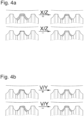
- FIG 4 a shows the influence of the tool feed towards the workpiece along the X1 or Z1 axis.
- a positive correction value on the X1 axis leads to a larger axis distance between the tool and workpiece axis, which reduces the chamfer size. Conversely, the chamfer becomes larger.
- a positive correction value leads to a narrower chamfer, a negative value brings the milling cutter closer to the workpiece and thus increases the chamfer.
- a tangential displacement of the tool to the workpiece in the direction of the Y1 axis leads to chamfers of different sizes between the left and right tooth flanks. If the chamfer on the left tooth flank is too large, it must be changed in the "plus direction" of the Y1 axis. A correction away from the right tooth flank is done via a "minus correction”. The effect is shown in the Fig. 4b This effect can also be achieved by an additional rotation around the C1 axis, as shown in the Fig. 4c can be recognized.
- the method according to the invention provides support, in which the machine operator only has to enter the measured values for the chamfer shape for the two tooth flanks and the machine control then subsequently determines the necessary corrections for several axes at the same time and takes them into account when machining the next workpiece.
- the Figures 5a to 5c each show the edge of a tooth flank with different parameters to describe the chamfer.
- Fig. 5b shows the relationship between chamfer width, chamfer size and chamfer angle for both the acute and the blunt chamfer. It is clearly visible that with the same values for the chamfer width and chamfer depth, a different chamfer angle is created because the helix angle of the gearing must also be taken into account.
- Fig. 5c shows the influence of the machining allowance ⁇ S on the chamfer sizes bF and tF.
Landscapes
- Engineering & Computer Science (AREA)
- Mechanical Engineering (AREA)
- Human Computer Interaction (AREA)
- Manufacturing & Machinery (AREA)
- Physics & Mathematics (AREA)
- General Physics & Mathematics (AREA)
- Automation & Control Theory (AREA)
- Gear Processing (AREA)
Claims (8)
- Procédé de correction de tailles de chanfrein, de formes de chanfrein et de symétrie de chanfrein sur des arêtes de dent qui ont été produites avec une fraise d'ébavurage (70) avec une forme de dent fortement asymétrique (ChamferCut) pour l'ébavurage d'une ébauche de roue dentée (50), caractérisé en ce qu'une correction semi-automatique des chanfreins, c'est-à-dire de la largeur de chanfrein et de la forme de chanfrein, a lieu par couplage du mouvement de plusieurs axes d'une machine à tailler les engrenages, qui présente au moins comme axe C1 un axe de rotation de la pièce, comme axes Z1, X1 et Y1 les axes de déplacement dans l'espace d'un chariot d'outil et comme direction V1 la direction de déplacement dans la direction axiale de l'axe d'outil, avec les étapes suivantes :- la prescription de la correction dans une direction axiale,- le calcul du montant de la correction nécessaire à cet effet pour d'autres axes par la commande par l'intermédiaire de fonctions trigonométriques lors- du couplage de l'axe C1 à l'axe Z1 par l'intermédiaire de l'angle d'inclinaison (β) de la denture dans le cas de la prescription de la correction dans la direction Z1 de telle sorte qu'une correction de la position de rotation (C1) de la pièce a lieu et- du couplage de l'axe C1 par l'intermédiaire de l'angle d'engrènement frontal (αt) de la denture et de l'axe Z1 par l'intermédiaire de l'angle de pivotement (η) de l'outil (70) à la direction V1 dans le cas de la prescription de la correction dans la direction Y1, de telle sorte que des corrections des axes C1 et Z1 ont lieu, et- du couplage de l'axe Y1 à l'axe C1 par l'intermédiaire de l'angle d'engrènement frontal (αt) de la denture dans le cas de la prescription de la correction dans la direction Y1, de telle sorte qu'une correction a lieu par l'intermédiaire de l'axe C1.
- Procédé selon la revendication 1, caractérisé en ce que la largeur de chanfrein pour le flanc gauche et/ou le flanc droit est corrigée automatiquement par l'intermédiaire de l'entrée de la largeur de chanfrein mesurée en comparaison avec les valeurs de consigne entrées.
- Procédé selon la revendication 1, caractérisé en ce que la largeur de chanfrein pour le flanc gauche et/ou le flanc droit est corrigée automatiquement en comparaison avec les valeurs de consigne entrées, en fonction d'un résultat de mesure qui a été déterminé au moyen d'un dispositif de mesure (palpeur de mesure) dans la machine à tailler les engrenages.
- Procédé selon l'une quelconque des revendications précédentes, caractérisé en ce que les données de la fraise sont transférées par l'intermédiaire d'un format de données électronique (par exemple XML).
- Procédé selon l'une quelconque des revendications précédentes, caractérisé en ce que les données de la fraise sont récupérées en ligne lors du reconditionnement de l'outil émoussé.
- Procédé selon l'une quelconque des revendications précédentes, caractérisé en ce que la largeur de chanfrein d'outils pré-dentés est convertie en outils à denture finie en tenant compte de la surépaisseur d'usinage sur le flanc de la dent.
- Procédé selon l'une quelconque des revendications précédentes, caractérisé en ce que les valeurs mesurées sont comparées aux valeurs du dessin, même si celles-ci ne sont pas disponibles dans le format mesuré.
- Dispositif (10) pour la mise en oeuvre d'un procédé selon l'une quelconque des revendications précédentes, avec une commande pour l'exécution automatique des étapes suivantes après prescription d'une correction dans une direction axiale :- le calcul du montant de la correction nécessaire à cet effet pour d'autres axes par la commande lors- du couplage de l'axe C1 à l'axe Z1 par l'intermédiaire de l'angle d'inclination (β) de la denture dans le cas de la prescription d'une correction dans la direction Z1, de telle sorte qu'une correction de la position de rotation (C1) de la pièce (50) a lieu et- du couplage de l'axe C1 par l'intermédiaire de l'angle d'engrènement frontal (αt) de la denture et de l'axe Z1 par l'intermédiaire de l'angle de pivotement (η) de l'outil à la direction V1 dans le cas de la prescription d'une correction dans la direction V1, de telle sorte que des corrections des axes C1 et Z1 ont lieu et- du couplage de l'axe Y1 à l'axe C1 par l'intermédiaire de l'angle d'engrènement frontal (αt) de la denture dans le cas de la prescription d'une correction dans la direction Y1, de telle sorte qu'une correction a lieu par l'intermédiaire de l'axe C1.
Applications Claiming Priority (1)
| Application Number | Priority Date | Filing Date | Title |
|---|---|---|---|
| DE102015012603.2A DE102015012603A1 (de) | 2015-09-28 | 2015-09-28 | Verfahren zum Entgraten eines Zahnradrohlings |
Publications (2)
| Publication Number | Publication Date |
|---|---|
| EP3147060A1 EP3147060A1 (fr) | 2017-03-29 |
| EP3147060B1 true EP3147060B1 (fr) | 2024-10-02 |
Family
ID=56682042
Family Applications (1)
| Application Number | Title | Priority Date | Filing Date |
|---|---|---|---|
| EP16183772.9A Active EP3147060B1 (fr) | 2015-09-28 | 2016-08-11 | Procede d'ebavurage d'une ebauche d'engrenage et dispositif pour la mise en oeuvre d'un tel procédé |
Country Status (6)
| Country | Link |
|---|---|
| US (1) | US10421136B2 (fr) |
| EP (1) | EP3147060B1 (fr) |
| JP (1) | JP7057060B2 (fr) |
| KR (1) | KR102616616B1 (fr) |
| CN (1) | CN106825785B (fr) |
| DE (1) | DE102015012603A1 (fr) |
Families Citing this family (18)
| Publication number | Priority date | Publication date | Assignee | Title |
|---|---|---|---|---|
| DE102017000072A1 (de) * | 2017-01-05 | 2018-07-05 | Liebherr-Verzahntechnik Gmbh | Verfahren zum automatischen Bestimmen der geometrischen Abmessungen eines Werkzeuges in einer Verzahnmaschine |
| CN108247148A (zh) * | 2018-02-06 | 2018-07-06 | 唐守林 | 一种复合加工装置 |
| DE102018001106A1 (de) * | 2018-02-08 | 2019-08-08 | Peter Sums | Verfahren und Vorrichtung zum Bearbeiten eines Zahnrads |
| US10710185B2 (en) * | 2018-02-15 | 2020-07-14 | Gleason-Pfauter Maschinenfabrik Gmbh | Method of preparing a machining process and chamfering station |
| DE102018001388A1 (de) * | 2018-02-21 | 2019-08-22 | EMAG GmbH & Co. KG | Verfahren und Vorrichtung zum Anfasen verzahnter Werkstücke |
| DE102018001389A1 (de) * | 2018-02-21 | 2019-08-22 | EMAG GmbH & Co. KG | Verfahren und Vorrichtung zum Anfasen verzahnter Werkstücke |
| DE102018108632A1 (de) * | 2018-04-11 | 2019-10-17 | Liebherr-Verzahntechnik Gmbh | Vorrichtung zur Anfasbearbeitung eines Werkstücks |
| CN109396568A (zh) * | 2018-09-12 | 2019-03-01 | 陕西法士特汽车传动集团有限责任公司 | 一种利用四轴数控铣床加工齿套槽口倒角的方法 |
| DE102018126699B4 (de) * | 2018-10-25 | 2020-10-15 | Volkswagen Aktiengesellschaft | Verfahren zur Herstellung von stirnradverzahnten Werkstücken sowie stirnradverzahntes Werkstück |
| DE102019131266A1 (de) | 2019-11-20 | 2021-05-20 | Schaeffler Technologies AG & Co. KG | Verfahren und Vorrichtung zum Entgraten eines innenverzahnten Werkstücks |
| DE102020004346A1 (de) | 2020-07-20 | 2022-01-20 | Gleason-Pfauter Maschinenfabrik Gmbh | Verfahren zur Verzahnungsbearbeitung |
| CN111922446B (zh) * | 2020-08-11 | 2022-10-28 | 重庆第二机床厂有限责任公司 | 一种齿轮倒棱刀总成和立式齿轮倒棱机 |
| CN111843570A (zh) * | 2020-08-18 | 2020-10-30 | 苏州麻雀智能科技有限公司 | 基于机器视觉的盘类零件柔性倒角机 |
| CN112091752A (zh) * | 2020-08-19 | 2020-12-18 | 黄秀荣 | 一种齿轮加工用毛刺抛光设备 |
| CN112427746A (zh) * | 2020-11-12 | 2021-03-02 | 苏州哈勒智能制造有限公司 | 一种齿轮齿形倒角设备及其加工方式 |
| KR102574814B1 (ko) * | 2021-03-18 | 2023-09-06 | 주식회사아일 | 챔퍼링 각도 및 절삭량 조절이 가능한 고정도 기어 챔퍼링 시스템 |
| KR102574818B1 (ko) * | 2021-03-18 | 2023-09-06 | 주식회사아일 | 챔퍼링 각도 및 절삭량 조절이 가능한 고정도 기어 챔퍼링 방법 |
| CN113172504A (zh) * | 2021-04-22 | 2021-07-27 | 玉林市达志机械配件有限公司 | 一种使用倒角机去齿圈根部披锋的方法及打磨装置 |
Family Cites Families (22)
| Publication number | Priority date | Publication date | Assignee | Title |
|---|---|---|---|---|
| US4548531A (en) * | 1983-05-03 | 1985-10-22 | United Technologies Corporation | Method for chamfering the edges of gear teeth |
| JPS61152320A (ja) * | 1985-06-06 | 1986-07-11 | Howa Mach Ltd | 数値制御歯車面取盤 |
| DE211127T1 (de) * | 1985-08-01 | 1987-07-23 | United Technologies Corp., Hartford, Conn. | Verfahren zum entgraten von zahnkanten. |
| US5116173A (en) * | 1991-02-26 | 1992-05-26 | The Gleason Works | Method of generating bevel and hypoid gears |
| US6584415B1 (en) * | 1998-08-28 | 2003-06-24 | Mori Seiki Co., Ltd. | Method of creating tool wear data, estimating tool wear and judging use of tool |
| JP2000180157A (ja) * | 1998-12-16 | 2000-06-30 | Super Silicon Kenkyusho:Kk | 平坦度測定センサ |
| DE10109117C1 (de) * | 2001-02-24 | 2002-07-25 | Klingelnberg Gmbh | Entgratvorrichtung für Kegelräder |
| US6840720B2 (en) * | 2001-06-21 | 2005-01-11 | The Gleason Works | Machine for deburring and fine machining of tooth flanks of toothed workpieces |
| US6757949B2 (en) * | 2002-03-27 | 2004-07-06 | New Venture Gear, Inc. | Combination gear hobber, chamfer/debur and shaver apparatus and method |
| JP3910482B2 (ja) * | 2002-04-26 | 2007-04-25 | Thk株式会社 | 数値制御工作機械における加工誤差補正方法及びこれを用いた研削盤 |
| DE10230148C5 (de) | 2002-07-04 | 2015-10-22 | Liebherr-Verzahntechnik Gmbh | Verfahren zum Bearbeiten von mittels Wälzfräsen hergestellten Zahnrädern |
| WO2004091864A2 (fr) * | 2003-04-08 | 2004-10-28 | Arvin Joseph L | Appareil et methode pour usiner des pieces |
| DE10330474B4 (de) | 2003-07-05 | 2009-03-05 | Fette Gmbh | Vorrichtung zur Herstellung eines Zahnrads aus einem Zahnradrohling |
| DE202004004480U1 (de) * | 2004-03-19 | 2004-06-03 | Klingelnberg Gmbh | Kegelrad-Verzahnmaschine zum Anfasen und/oder Entgraten von Kanten an den Zähnen eines Kegelrades |
| JP4202306B2 (ja) * | 2004-07-29 | 2008-12-24 | 三菱重工業株式会社 | 歯車研削盤 |
| DE202005011790U1 (de) * | 2005-07-22 | 2005-10-20 | Gleason-Pfauter Maschinenfabrik Gmbh | Verzahnmaschine, insbesondere Kegelrad-Verzahnmaschine, mit einer Vorrichtung zum Anfasen/Entgraten der Kanten eines Werkstückes |
| DE102005054237A1 (de) | 2005-11-14 | 2007-05-16 | Weigl Engineering Gmbh | Verfahren und Vorrichtung zur Herstellung von Dachflächen und Anfasungen an verzahnten Getriebekomponenten |
| RU2424880C2 (ru) * | 2006-02-10 | 2011-07-27 | КЛИНГЕЛЬНБЕРГ ГмбХ | Устройство и способ обработки конических зубчатых колес с полной компенсацией ошибки деления |
| CN102548698B (zh) | 2009-09-25 | 2014-09-10 | 格里森工场 | 用于齿轮的倒角和/或去毛刺的设备 |
| KR101535305B1 (ko) * | 2009-10-09 | 2015-07-08 | 두산인프라코어 주식회사 | 선삭 가공 시스템에서의 공구 경로 생성 방법 |
| DE102011006993B4 (de) * | 2011-04-07 | 2025-10-09 | MODUL MT Verzahntechnik GmbH | Verfahren zur Herstellung von Verzahnungen an Werkstücken |
| DE102013015240A1 (de) | 2013-03-28 | 2014-10-02 | Liebherr-Verzahntechnik Gmbh | Vorrichtung und Verfahren zum Anfasen eines Werkstücks |
-
2015
- 2015-09-28 DE DE102015012603.2A patent/DE102015012603A1/de active Pending
-
2016
- 2016-08-11 EP EP16183772.9A patent/EP3147060B1/fr active Active
- 2016-09-21 JP JP2016184780A patent/JP7057060B2/ja active Active
- 2016-09-27 CN CN201610857369.3A patent/CN106825785B/zh active Active
- 2016-09-27 US US15/277,113 patent/US10421136B2/en active Active
- 2016-09-28 KR KR1020160124583A patent/KR102616616B1/ko active Active
Also Published As
| Publication number | Publication date |
|---|---|
| JP2017064903A (ja) | 2017-04-06 |
| KR102616616B1 (ko) | 2023-12-26 |
| US10421136B2 (en) | 2019-09-24 |
| EP3147060A1 (fr) | 2017-03-29 |
| CN106825785B (zh) | 2020-04-21 |
| US20170087653A1 (en) | 2017-03-30 |
| JP7057060B2 (ja) | 2022-04-19 |
| CN106825785A (zh) | 2017-06-13 |
| KR20170037857A (ko) | 2017-04-05 |
| DE102015012603A1 (de) | 2017-03-30 |
Similar Documents
| Publication | Publication Date | Title |
|---|---|---|
| EP3147060B1 (fr) | Procede d'ebavurage d'une ebauche d'engrenage et dispositif pour la mise en oeuvre d'un tel procédé | |
| EP2385885B2 (fr) | Dispositif et procédé pour tailler des dents dans des pièces | |
| DE3150961C2 (de) | Verfahren und Einrichtung zur Bearbeitung eines Zahnrades mittels eines rotierenden, zahnradartigen Werkzeuges | |
| DE3134147C2 (fr) | ||
| DE102014018328B4 (de) | Verfahren zum bearbeiten einer verzahnung, werkzeuganordnung und verzahnungsmaschine | |
| EP3439819B1 (fr) | Procédé de chanfreinage par enlèvement de matière d'une arête frontale de denture d'engrenage et dispositif conçu à cet effet | |
| EP3552744A1 (fr) | Dispositif et procédé de traitement par chanfreinage d'une pièce à usiner | |
| EP2520391A1 (fr) | Procédé de taillage de cylindres et dispositif correspondant doté d'un outil de taillage de cylindres | |
| EP1319457B2 (fr) | Procédé d'usinage de roues dentées essentiellement cylindriques à denture intérieure ou extérieure | |
| EP3012056A1 (fr) | Procede et dispositif de chanfreinage et d'ebavurage de pieces endentees | |
| EP2923790B1 (fr) | Procédé de meulage de roues coniques dans un procédé de rectification en bout | |
| DE102010061432B4 (de) | Verfahren und Werkzeug zur Herstellung eines Zahnrades mit balligen Zähnen | |
| EP3139227B1 (fr) | Procede de fabrication d'une piece usinee presentant une geometrie de denture souhaitee | |
| DE10230148C5 (de) | Verfahren zum Bearbeiten von mittels Wälzfräsen hergestellten Zahnrädern | |
| DE69406444T2 (de) | Werkzeug zur herstellung eines kronenrades, das mit einem schrägstirnrad zusammenwirken kann und ein verfahren zur herstellung eines derartigen kronenrades | |
| DE20320294U1 (de) | Vorrichtung zur Herstellung eines Zahnrads | |
| EP2420906B1 (fr) | Procédé et dispositif de production de données de commande pour la formation d'une dent d'une denture à renvoi à l'aide d'un traitement par fraisage d'une pièce usinée sur une machine-outil | |
| EP3341802B1 (fr) | Procédé de réalisation ou d'usinage de dentures sur des pieces | |
| DE102007039959A1 (de) | Verfahren und Profilwalzmaschine zum Kaltwalzen von längsgerichteten Verzahnungen und Profilen bei langen wellenförmigen Werkstücken | |
| DE102014019553A1 (de) | Verfahren zum Bearbeiten eines Werkstücks mit einer mehrgängigen Schleifschnecke und Abrichtverfahren dazu | |
| WO2019161823A1 (fr) | Procédé et dispositif pour chanfreiner des pièces dentées | |
| EP3039495B1 (fr) | Procédé d'ajustement de la consommation d'énergie de deux outils lors de l'usinage des extrémités de tronçons de tubes | |
| DE102018103691A1 (de) | Verfahren zum Tiefschleifen von Kegelrad-Werkstücken | |
| DE1075922B (de) | Verfahren und Vorrichtung zum spanlosen Entgraten der Zaehne und/oder zur Erzeugung von Abschraegungen an den Zahnkanten von Zahnraedern und anderen verzahnten Werkstuecken | |
| WO2019161822A1 (fr) | Procédé et dispositif destinés à rogner des pièces à usiner dentées |
Legal Events
| Date | Code | Title | Description |
|---|---|---|---|
| PUAI | Public reference made under article 153(3) epc to a published international application that has entered the european phase |
Free format text: ORIGINAL CODE: 0009012 |
|
| STAA | Information on the status of an ep patent application or granted ep patent |
Free format text: STATUS: THE APPLICATION HAS BEEN PUBLISHED |
|
| AK | Designated contracting states |
Kind code of ref document: A1 Designated state(s): AL AT BE BG CH CY CZ DE DK EE ES FI FR GB GR HR HU IE IS IT LI LT LU LV MC MK MT NL NO PL PT RO RS SE SI SK SM TR |
|
| AX | Request for extension of the european patent |
Extension state: BA ME |
|
| STAA | Information on the status of an ep patent application or granted ep patent |
Free format text: STATUS: REQUEST FOR EXAMINATION WAS MADE |
|
| 17P | Request for examination filed |
Effective date: 20170929 |
|
| STAA | Information on the status of an ep patent application or granted ep patent |
Free format text: STATUS: EXAMINATION IS IN PROGRESS |
|
| 17Q | First examination report despatched |
Effective date: 20180413 |
|
| GRAP | Despatch of communication of intention to grant a patent |
Free format text: ORIGINAL CODE: EPIDOSNIGR1 |
|
| STAA | Information on the status of an ep patent application or granted ep patent |
Free format text: STATUS: GRANT OF PATENT IS INTENDED |
|
| RIC1 | Information provided on ipc code assigned before grant |
Ipc: B23F 23/12 20060101ALI20240312BHEP Ipc: B23F 19/10 20060101AFI20240312BHEP |
|
| INTG | Intention to grant announced |
Effective date: 20240404 |
|
| GRAS | Grant fee paid |
Free format text: ORIGINAL CODE: EPIDOSNIGR3 |
|
| GRAA | (expected) grant |
Free format text: ORIGINAL CODE: 0009210 |
|
| STAA | Information on the status of an ep patent application or granted ep patent |
Free format text: STATUS: THE PATENT HAS BEEN GRANTED |
|
| AK | Designated contracting states |
Kind code of ref document: B1 Designated state(s): AL AT BE BG CH CY CZ DE DK EE ES FI FR GB GR HR HU IE IS IT LI LT LU LV MC MK MT NL NO PL PT RO RS SE SI SK SM TR |
|
| REG | Reference to a national code |
Ref country code: GB Ref legal event code: FG4D Free format text: NOT ENGLISH |
|
| REG | Reference to a national code |
Ref country code: CH Ref legal event code: EP |
|
| REG | Reference to a national code |
Ref country code: DE Ref legal event code: R096 Ref document number: 502016016736 Country of ref document: DE |
|
| REG | Reference to a national code |
Ref country code: IE Ref legal event code: FG4D Free format text: LANGUAGE OF EP DOCUMENT: GERMAN |
|
| REG | Reference to a national code |
Ref country code: LT Ref legal event code: MG9D |
|
| REG | Reference to a national code |
Ref country code: NL Ref legal event code: MP Effective date: 20241002 |
|
| PG25 | Lapsed in a contracting state [announced via postgrant information from national office to epo] |
Ref country code: NL Free format text: LAPSE BECAUSE OF FAILURE TO SUBMIT A TRANSLATION OF THE DESCRIPTION OR TO PAY THE FEE WITHIN THE PRESCRIBED TIME-LIMIT Effective date: 20241002 |
|
| PG25 | Lapsed in a contracting state [announced via postgrant information from national office to epo] |
Ref country code: NL Free format text: LAPSE BECAUSE OF FAILURE TO SUBMIT A TRANSLATION OF THE DESCRIPTION OR TO PAY THE FEE WITHIN THE PRESCRIBED TIME-LIMIT Effective date: 20241002 |
|
| PG25 | Lapsed in a contracting state [announced via postgrant information from national office to epo] |
Ref country code: IS Free format text: LAPSE BECAUSE OF FAILURE TO SUBMIT A TRANSLATION OF THE DESCRIPTION OR TO PAY THE FEE WITHIN THE PRESCRIBED TIME-LIMIT Effective date: 20250202 Ref country code: HR Free format text: LAPSE BECAUSE OF FAILURE TO SUBMIT A TRANSLATION OF THE DESCRIPTION OR TO PAY THE FEE WITHIN THE PRESCRIBED TIME-LIMIT Effective date: 20241002 Ref country code: PT Free format text: LAPSE BECAUSE OF FAILURE TO SUBMIT A TRANSLATION OF THE DESCRIPTION OR TO PAY THE FEE WITHIN THE PRESCRIBED TIME-LIMIT Effective date: 20250203 |
|
| PG25 | Lapsed in a contracting state [announced via postgrant information from national office to epo] |
Ref country code: FI Free format text: LAPSE BECAUSE OF FAILURE TO SUBMIT A TRANSLATION OF THE DESCRIPTION OR TO PAY THE FEE WITHIN THE PRESCRIBED TIME-LIMIT Effective date: 20241002 |
|
| PG25 | Lapsed in a contracting state [announced via postgrant information from national office to epo] |
Ref country code: BG Free format text: LAPSE BECAUSE OF FAILURE TO SUBMIT A TRANSLATION OF THE DESCRIPTION OR TO PAY THE FEE WITHIN THE PRESCRIBED TIME-LIMIT Effective date: 20241002 |
|
| PG25 | Lapsed in a contracting state [announced via postgrant information from national office to epo] |
Ref country code: ES Free format text: LAPSE BECAUSE OF FAILURE TO SUBMIT A TRANSLATION OF THE DESCRIPTION OR TO PAY THE FEE WITHIN THE PRESCRIBED TIME-LIMIT Effective date: 20241002 |
|
| PG25 | Lapsed in a contracting state [announced via postgrant information from national office to epo] |
Ref country code: NO Free format text: LAPSE BECAUSE OF FAILURE TO SUBMIT A TRANSLATION OF THE DESCRIPTION OR TO PAY THE FEE WITHIN THE PRESCRIBED TIME-LIMIT Effective date: 20250102 |
|
| PG25 | Lapsed in a contracting state [announced via postgrant information from national office to epo] |
Ref country code: GR Free format text: LAPSE BECAUSE OF FAILURE TO SUBMIT A TRANSLATION OF THE DESCRIPTION OR TO PAY THE FEE WITHIN THE PRESCRIBED TIME-LIMIT Effective date: 20250103 Ref country code: LV Free format text: LAPSE BECAUSE OF FAILURE TO SUBMIT A TRANSLATION OF THE DESCRIPTION OR TO PAY THE FEE WITHIN THE PRESCRIBED TIME-LIMIT Effective date: 20241002 |
|
| PG25 | Lapsed in a contracting state [announced via postgrant information from national office to epo] |
Ref country code: CZ Free format text: LAPSE BECAUSE OF FAILURE TO SUBMIT A TRANSLATION OF THE DESCRIPTION OR TO PAY THE FEE WITHIN THE PRESCRIBED TIME-LIMIT Effective date: 20241002 Ref country code: PL Free format text: LAPSE BECAUSE OF FAILURE TO SUBMIT A TRANSLATION OF THE DESCRIPTION OR TO PAY THE FEE WITHIN THE PRESCRIBED TIME-LIMIT Effective date: 20241002 |
|
| PG25 | Lapsed in a contracting state [announced via postgrant information from national office to epo] |
Ref country code: RS Free format text: LAPSE BECAUSE OF FAILURE TO SUBMIT A TRANSLATION OF THE DESCRIPTION OR TO PAY THE FEE WITHIN THE PRESCRIBED TIME-LIMIT Effective date: 20250102 |
|
| PG25 | Lapsed in a contracting state [announced via postgrant information from national office to epo] |
Ref country code: SM Free format text: LAPSE BECAUSE OF FAILURE TO SUBMIT A TRANSLATION OF THE DESCRIPTION OR TO PAY THE FEE WITHIN THE PRESCRIBED TIME-LIMIT Effective date: 20241002 |
|
| REG | Reference to a national code |
Ref country code: DE Ref legal event code: R097 Ref document number: 502016016736 Country of ref document: DE |
|
| PG25 | Lapsed in a contracting state [announced via postgrant information from national office to epo] |
Ref country code: DK Free format text: LAPSE BECAUSE OF FAILURE TO SUBMIT A TRANSLATION OF THE DESCRIPTION OR TO PAY THE FEE WITHIN THE PRESCRIBED TIME-LIMIT Effective date: 20241002 |
|
| PG25 | Lapsed in a contracting state [announced via postgrant information from national office to epo] |
Ref country code: EE Free format text: LAPSE BECAUSE OF FAILURE TO SUBMIT A TRANSLATION OF THE DESCRIPTION OR TO PAY THE FEE WITHIN THE PRESCRIBED TIME-LIMIT Effective date: 20241002 |
|
| PG25 | Lapsed in a contracting state [announced via postgrant information from national office to epo] |
Ref country code: RO Free format text: LAPSE BECAUSE OF FAILURE TO SUBMIT A TRANSLATION OF THE DESCRIPTION OR TO PAY THE FEE WITHIN THE PRESCRIBED TIME-LIMIT Effective date: 20241002 |
|
| PG25 | Lapsed in a contracting state [announced via postgrant information from national office to epo] |
Ref country code: SK Free format text: LAPSE BECAUSE OF FAILURE TO SUBMIT A TRANSLATION OF THE DESCRIPTION OR TO PAY THE FEE WITHIN THE PRESCRIBED TIME-LIMIT Effective date: 20241002 |
|
| PLBE | No opposition filed within time limit |
Free format text: ORIGINAL CODE: 0009261 |
|
| STAA | Information on the status of an ep patent application or granted ep patent |
Free format text: STATUS: NO OPPOSITION FILED WITHIN TIME LIMIT |
|
| PG25 | Lapsed in a contracting state [announced via postgrant information from national office to epo] |
Ref country code: SE Free format text: LAPSE BECAUSE OF FAILURE TO SUBMIT A TRANSLATION OF THE DESCRIPTION OR TO PAY THE FEE WITHIN THE PRESCRIBED TIME-LIMIT Effective date: 20241002 |
|
| 26N | No opposition filed |
Effective date: 20250703 |
|
| PGFP | Annual fee paid to national office [announced via postgrant information from national office to epo] |
Ref country code: DE Payment date: 20250828 Year of fee payment: 10 |
|
| PGFP | Annual fee paid to national office [announced via postgrant information from national office to epo] |
Ref country code: IT Payment date: 20250827 Year of fee payment: 10 |
|
| PGFP | Annual fee paid to national office [announced via postgrant information from national office to epo] |
Ref country code: CH Payment date: 20250901 Year of fee payment: 10 |
|
| PG25 | Lapsed in a contracting state [announced via postgrant information from national office to epo] |
Ref country code: MC Free format text: LAPSE BECAUSE OF FAILURE TO SUBMIT A TRANSLATION OF THE DESCRIPTION OR TO PAY THE FEE WITHIN THE PRESCRIBED TIME-LIMIT Effective date: 20241002 |
|
| PG25 | Lapsed in a contracting state [announced via postgrant information from national office to epo] |
Ref country code: LU Free format text: LAPSE BECAUSE OF NON-PAYMENT OF DUE FEES Effective date: 20250811 |