EP3147064A1 - Procédé de commande de soudage à l'arc - Google Patents
Procédé de commande de soudage à l'arc Download PDFInfo
- Publication number
- EP3147064A1 EP3147064A1 EP15795407.4A EP15795407A EP3147064A1 EP 3147064 A1 EP3147064 A1 EP 3147064A1 EP 15795407 A EP15795407 A EP 15795407A EP 3147064 A1 EP3147064 A1 EP 3147064A1
- Authority
- EP
- European Patent Office
- Prior art keywords
- period
- welding
- feeding
- signal
- constriction
- Prior art date
- Legal status (The legal status is an assumption and is not a legal conclusion. Google has not performed a legal analysis and makes no representation as to the accuracy of the status listed.)
- Granted
Links
Images



Classifications
-
- B—PERFORMING OPERATIONS; TRANSPORTING
- B23—MACHINE TOOLS; METAL-WORKING NOT OTHERWISE PROVIDED FOR
- B23K—SOLDERING OR UNSOLDERING; WELDING; CLADDING OR PLATING BY SOLDERING OR WELDING; CUTTING BY APPLYING HEAT LOCALLY, e.g. FLAME CUTTING; WORKING BY LASER BEAM
- B23K9/00—Arc welding or cutting
- B23K9/12—Automatic feeding or moving of electrodes or work for spot or seam welding or cutting
- B23K9/124—Circuits or methods for feeding welding wire
- B23K9/125—Feeding of electrodes
-
- B—PERFORMING OPERATIONS; TRANSPORTING
- B23—MACHINE TOOLS; METAL-WORKING NOT OTHERWISE PROVIDED FOR
- B23K—SOLDERING OR UNSOLDERING; WELDING; CLADDING OR PLATING BY SOLDERING OR WELDING; CUTTING BY APPLYING HEAT LOCALLY, e.g. FLAME CUTTING; WORKING BY LASER BEAM
- B23K9/00—Arc welding or cutting
- B23K9/06—Arrangements or circuits for starting the arc, e.g. by generating ignition voltage, or for stabilising the arc
- B23K9/073—Stabilising the arc
-
- B—PERFORMING OPERATIONS; TRANSPORTING
- B23—MACHINE TOOLS; METAL-WORKING NOT OTHERWISE PROVIDED FOR
- B23K—SOLDERING OR UNSOLDERING; WELDING; CLADDING OR PLATING BY SOLDERING OR WELDING; CUTTING BY APPLYING HEAT LOCALLY, e.g. FLAME CUTTING; WORKING BY LASER BEAM
- B23K9/00—Arc welding or cutting
- B23K9/09—Arrangements or circuits for arc welding with pulsed current or voltage
-
- B—PERFORMING OPERATIONS; TRANSPORTING
- B23—MACHINE TOOLS; METAL-WORKING NOT OTHERWISE PROVIDED FOR
- B23K—SOLDERING OR UNSOLDERING; WELDING; CLADDING OR PLATING BY SOLDERING OR WELDING; CUTTING BY APPLYING HEAT LOCALLY, e.g. FLAME CUTTING; WORKING BY LASER BEAM
- B23K9/00—Arc welding or cutting
- B23K9/095—Monitoring or automatic control of welding parameters
- B23K9/0956—Monitoring or automatic control of welding parameters using sensing means, e.g. optical
-
- B—PERFORMING OPERATIONS; TRANSPORTING
- B23—MACHINE TOOLS; METAL-WORKING NOT OTHERWISE PROVIDED FOR
- B23K—SOLDERING OR UNSOLDERING; WELDING; CLADDING OR PLATING BY SOLDERING OR WELDING; CUTTING BY APPLYING HEAT LOCALLY, e.g. FLAME CUTTING; WORKING BY LASER BEAM
- B23K9/00—Arc welding or cutting
- B23K9/10—Other electric circuits therefor; Protective circuits; Remote controls
- B23K9/1006—Power supply
-
- B—PERFORMING OPERATIONS; TRANSPORTING
- B23—MACHINE TOOLS; METAL-WORKING NOT OTHERWISE PROVIDED FOR
- B23K—SOLDERING OR UNSOLDERING; WELDING; CLADDING OR PLATING BY SOLDERING OR WELDING; CUTTING BY APPLYING HEAT LOCALLY, e.g. FLAME CUTTING; WORKING BY LASER BEAM
- B23K9/00—Arc welding or cutting
- B23K9/12—Automatic feeding or moving of electrodes or work for spot or seam welding or cutting
-
- B—PERFORMING OPERATIONS; TRANSPORTING
- B23—MACHINE TOOLS; METAL-WORKING NOT OTHERWISE PROVIDED FOR
- B23K—SOLDERING OR UNSOLDERING; WELDING; CLADDING OR PLATING BY SOLDERING OR WELDING; CUTTING BY APPLYING HEAT LOCALLY, e.g. FLAME CUTTING; WORKING BY LASER BEAM
- B23K9/00—Arc welding or cutting
- B23K9/16—Arc welding or cutting making use of shielding gas
- B23K9/173—Arc welding or cutting making use of shielding gas and of a consumable electrode
Definitions
- the present invention relates to an arc welding control method of alternating a forward feeding period and a reverse feeding period cyclically as to a feeding rate of a welding wire to generate short-circuiting periods and arc periods in a manner that shifting to the arc period is performed by reducing a welding current when a constriction of a droplet formed at the welding wire is detected during the short-circuiting period.
- a typical consumable electrode arc welding welding is performed by feeding a welding wire as a consumable electrode at a constant feeding rate and generating an arc between the welding wire and base material.
- both the welding wire and the base material are mostly placed in a welding state in which a short circuit state and an arc generation state are alternately repeated.
- Patent Document 1 a method of performing welding by alternating feeding of a welding wire between forward feeding and reverse feeding cyclically. Further there has been proposed a constriction detection control method in which a generation amount of spatter is reduced by rapidly reducing a welding current in response to detection of a constriction of a droplet, as a precursory phenomenon of arc regeneration, and regenerating an arc in a small current-value state (see Patent Document 2, for example).
- Patent Document 1 a method of performing welding by alternating feeding of a welding wire between forward feeding and reverse feeding cyclically
- Patent Document 2 a constriction detection control method in which a generation amount of spatter is reduced by rapidly reducing a welding current in response to detection of a constriction of a droplet, as a precursory phenomenon of arc regeneration, and regenerating an arc in a small current-value state.
- Fig. 4 is a waveform diagram of the welding method in which the forward feeding period and the reverse feeding period are alternated cyclically as to the feeding rate of the welding wire and also constriction detection control is performed.
- A) of this figure shows a waveform of a feeding rate Fw
- B) of this figure shows a waveform of a welding current Iw
- C) of this figure shows a waveform of a welding voltage Vw.
- an upper side and a lower side than 0 represent a forward feeding period and a reverse feeding period, respectively.
- the forward feeding represents feeding of the welding wire in a direction approaching the base material
- the reverse feeding represents feeding of the welding wire in a direction separating from the base material.
- the feeding rate Fw has a waveform which changes sinusoidally and shifts on the forward feeding side. Thus as an average value of the feeding rate Fw is positive, the welding wire is fed forwardly in average.
- the feeding rate Fw is 0 at a time t1.
- a period from the time t1 to a time t2 corresponds to a forward feeding acceleration period.
- the feeding rate is the maximum value of the forward feeding at the time t2.
- a period from the time t2 to a time t3 corresponds to a forward feeding deceleration period.
- the feeding rate is 0 at the time t3.
- a period from the time t3 to a time t4 corresponds to a reverse feeding acceleration period.
- the feeding rate is the maximum value of the reverse feeding at the time t4.
- a period from the time t4 to a time t5 corresponds to a reverse feeding deceleration period.
- the feeding rate Fw changes repeatedly with a single cycle from the time t1 to the time t5.
- Short circuit between the welding wire and the base material occurs mostly before or after the maximum value of the forward feeding at the time t2.
- This figure shows a case where the short circuit occurs at a time t21 during the forward feeding deceleration period after the maximum value of the forward feeding. If the short circuit occurs at the time t21, the welding voltage Vw reduces rapidly to a short-circuit voltage value of a few volts as shown in (C) of this figure, and the welding current Iw also reduces to an initial current value of a small current value as shown in (B) of this figure. Thereafter the welding current Iw increases with a predetermined inclination. When the welding current reaches a predetermined peak value, the welding current is maintained at this value.
- the welding voltage Vw increases rapidly to an arc voltage value of several tens of volts as shown in (C) of this figure.
- the welding current Iw rapidly reduces from a time earlier than the time t31 by several hundreds of ⁇ s and becomes a small current value at the arc regeneration time t31.
- a constriction is formed at the droplet, as a current path becomes narrow, a resistance value or the welding voltage value between the welding wire and the base material increases. The constriction is detected by detecting this voltage increase.
- the feeding rate Fw is placed in a reverse feeding state.
- An arc length becomes long during this period.
- the welding current Iw increases with a predetermined inclination, then reaches a predetermined first welding current value and maintains this value until a predetermined period elapses after the arc regeneration (time t31). Thereafter a second welding current smaller than the first welding current flows until a time 61 at which the next short circuit occurs.
- the feeding rate Fw is placed in the forward feeding period from the time t5 and reaches a forward feeding peak value at a time t6. Then the next short circuit occurs at a time t61.
- the welding voltage Vw reduces gradually as shown in (C) of this figure, and the welding current Iw also reduces gradually as shown in (B) of this figure.
- a cycle of the short circuit and the arc is substantially the same as a cycle of the forward feeding and the reverse feeding as to the feeding rate. That is, according to this welding method, the cycle of short circuit and arc can be set to a desired value by suitably setting the cycle of forward feeding and reverse feeding as to the feeding rate. Thus if this welding method is implemented, the cycle of short circuit and arc can be suppressed in its variance and made substantially constant. Consequently, in combination with the constriction detection control, the welding can be performed with a small generation amount of the spatter and with good bead appearance.
- the welding can be performed stably with a small generation amount of the spatter by cyclically alternating the forward feeding period and the reverse feeding period as to the feeding rate and performing the constriction detection control.
- a waveform parameter amplitude, cycle or the like
- the waveform parameter of feeding rate is sometimes changed according to a demand for setting the bead appearance to a desired shape, or a demand for adjusting feeling of an arc to worker's preference, for example.
- an object of the present invention is to provide an arc welding control method which, in a welding method of cyclically alternating a forward feeding period and a reverse feeding period as to a feeding rate and performing constriction detection control, can suppress the constriction detection control becoming unstable when a waveform parameter of the feeding rate changes.
- an arc welding control method of alternating a forward feeding period and a reverse feeding period cyclically as to a feeding rate of a welding wire to generate short-circuiting periods and arc periods in a manner that shifting to the arc period is performed by reducing a welding current when a constriction of a droplet formed at the welding wire is detected during the short-circuiting period, the arc welding control method comprising: changing sensitivity of the detection of constriction according to a waveform parameter of the feeding rate.
- the waveform parameter of feeding rate is at least one or more of an amplitude, a cycle and a ratio between the forward feeding period and the reverse feeding period.
- the constriction detection control can be suppressed becoming unstable.
- Fig. 1 is a block diagram illustrating a welding power supply for implementing an arc welding control method according to a first embodiment of the present invention. Hereinafter individual blocks will be explained with reference to this figure.
- a power supply main circuit PM subjects the input power to output control such as inverter control according to an error amplified signal Ea described later, and outputs a welding voltage Vw and a welding current Iw.
- this power supply main circuit PM includes a primary rectifier for rectifying the commercial power supply, a smoothing capacitor for smoothing the rectified DC, an inverter circuit for converting the smoothed DC into a high-frequency AC, a high-frequency transformer for stepping down the high-frequency AC to a voltage value suitable for welding, a secondary rectifier for rectifying the stepped-down high-frequency AC to a DC, a reactor for smoothing the rectified DC, a modulation circuit which performs a pulse width modulation control using the error amplified signal Ea as input, and an inverter driving circuit which drives switching elements of the inverter circuit using a pulse width modulation control signal as input.
- a current decreasing resistor R is inserted between the power supply main circuit PM and a welding torch 4.
- the current decreasing resistor R is set to a value (about 0.5 to 3 ⁇ ) ten times or more as large as that of a short-circuit load (about 0.01 to 0.032 ⁇ ).
- a transistor TR is connected in parallel to the current decreasing resistor R and controlled so as to be turned on/off according to a drive signal Dr described later.
- a feeding motor WM feeds a welding wire 1 at a feeding rate Fw in a manner of alternating forward feeding and reverse feeding cyclically.
- a motor having high transient responsiveness is used as the feeding motor WM.
- the feeding motor WM is installed near a tip of the welding torch 4 in order to increase a change rate of the feeding rate Fw and an inversion speed of the feeding direction of the welding wire 1.
- a push-pull feeding system is configured by using two feeding motors WM.
- the welding wire 1 is fed within the welding torch 4 in accordance with rotation of a feeding roll 5 coupled to the feeding motor WM, and thus an arc 3 is generated between this wire and base material 2.
- the welding voltage Vw is applied between a power supply tip (not shown) within the welding torch 4 and the base material 2, and thus the welding current Iw flows.
- a welding current detection circuit ID detects the welding current Iw and outputs a welding current detection signal Id.
- a welding voltage detection circuit VD detects the welding voltage Vw and outputs a welding voltage detection signal Vd.
- a short-circuit discrimination circuit SD uses the welding voltage detection signal Vd as input, a short-circuit discrimination circuit SD outputs a short-circuit discrimination signal Sd.
- the discrimination circuit determines to be a short-circuiting period and outputs the discrimination signal of a high level.
- the discrimination circuit determines to be an arc period and outputs the discrimination signal of a low level.
- An average feeding-rate setting circuit FAR outputs an average feeding-rate setting signal Far set in advance.
- An amplitude fine-adjustment circuit WFR outputs an amplitude fine-adjustment signal Wfr for finely adjusting an amplitude of the feeding rate.
- a cycle fine-adjustment circuit TFR outputs a cycle fine-adjustment signal Tfr for finely adjusting a cycle of the feeding rate.
- a forward/reverse ratio fine-adjustment circuit DFR outputs a forward/reverse ratio fine-adjustment signal Dfr for finely adjusting a ratio between the forward feeding period and the reverse feeding period of feeding rate (hereinafter referred to as forward/reverse ratio) D.
- the forward/reverse ratio D represents (reverse feeding period)/(forward feeding period).
- a feeding-rate setting circuit FR uses the average feeding-rate setting signal Far, the amplitude fine-adjustment signal Wfr, the cycle fine-adjustment signal Tfr and the forward/reverse ratio fine-adjustment signal Dfr as input, a feeding-rate setting circuit FR outputs a feeding-rate setting signal Fr having a pattern formed by waveform parameters.
- the waveform parameters an amplitude standard value, a cycle standard value and a forward/reverse ratio standard value, each preset in correspondence to the average feeding-rate setting signal Far, are finely adjusted by individual values of the amplitude fine-adjustment signal Wfr, the cycle fine-adjustment signal Tfr and the forward/reverse ratio fine-adjustment signal Dfr, respectively.
- the amplitude standard value is calculated according to a predetermined amplitude calculation function. Then an amplitude setting value is obtained by summing the amplitude standard value and the amplitude fine-adjustment signal Wfr.
- the amplitude setting value is 80m/min in a case where the amplitude standard value and Wfr are 90m/min and -10m/min, respectively.
- the cycle setting value and the forward/reverse ratio setting value are calculated.
- Wfr, Tfr and Dfr takes positive and negative values.
- the feeding-rate setting signal Fr alternating the forward feeding period and the reverse feeding period in a sinusoidal wave manner is outputted.
- the feeding-rate setting signal Fr may have a pattern of a trapezoidal wave, a triangular wave or the like.
- a feeding control circuit FC outputs, to the feeding motor WM, the feeding control signal Fc for feeding the welding wire 1 at the feeding rate Fw corresponding to the setting values of this setting signal.
- a first welding current setting circuit IWR1 outputs a predetermined first welding current setting signal Iwr1.
- a first welding current conduction-period setting circuit TWR1 outputs a predetermined first welding current conduction-period setting signal Twr1.
- a constriction detection-sensitivity setting circuit NTR calculates a constriction detection-sensitivity standard value Nts according to a predetermined constriction detection-sensitivity calculation function based on the average feeding-rate setting signal Far.
- the constriction detection-sensitivity setting circuit corrects the constriction detection-sensitivity standard value Nts using individual values of the amplitude fine-adjustment signal Wfr, the cycle fine-adjustment signal Tfr and the forward/reverse ratio fine-adjustment signal Dfr, and outputs the corrected value as a constriction detection-sensitivity setting signal Ntr.
- the constriction detection-sensitivity standard value Nts is corrected to reduce the sensitivity when the amplitude fine-adjustment signal Wfr has a positive value, whilst corrected to increase the sensitivity when the signal has a negative value.
- the constriction detection-sensitivity standard value Nts is corrected to reduce the sensitivity when the cycle fine-adjustment signal Tfr has a positive value, whilst corrected to increase the sensitivity when the signal has a negative value.
- the constriction detection-sensitivity standard value Nts is corrected to reduce the sensitivity when the forward/reverse ratio fine-adjustment signal Dfr has a positive value, whilst corrected to increase the sensitivity when the signal has a negative value.
- a constriction detection circuit ND uses the short-circuit discrimination signal Sd, the welding voltage detection signal Vd, the welding current detection signal Id and the constriction detection-sensitivity setting signal Ntr as input, a constriction detection circuit ND outputs a constriction detection signal Nd.
- a voltage increasing value of the welding voltage detection signal Vd during the high level (short-circuiting period) of the short-circuit discrimination signal Sd reaches a value of the constriction detection-sensitivity setting signal Ntr, the constriction detection circuit determines that a forming state of the constriction becomes a reference state and outputs the constriction detection signal of a high level.
- the narrow-part detection circuit outputs the constriction detection signal of a low level when the short-circuit discrimination signal Sd changes to the low level (arc period).
- the constriction detection signal Nd may be changed to the high level when a differential value of the welding voltage detection signal Vd in the short-circuiting period reaches a value of the constriction detection-sensitivity setting signal Ntr corresponding thereto.
- a resistance value of a droplet may be calculated by dividing a value of the welding voltage detection signal Vd by a value of the welding current detection signal Id. Then the constriction detection signal Nd may be changed to the high level when a differential value of the resistance value reaches a value of the constriction detection-sensitivity setting signal Ntr corresponding thereto.
- a low-level current setting circuit ILR outputs a predetermined low-level current setting signal Ilr.
- a current comparison circuit CM uses the low-level current setting signal Ilr and the welding current detection signal Id as input, a current comparison circuit CM outputs a current comparison signal Cm which becomes a high level in a case of Id ⁇ Ilr and a low level in a case of Id ⁇ Ilr.
- a driving circuit DR uses the current comparison signal Cm and the constriction detection signal Nd as input, a driving circuit DR outputs, to a base terminal of the transistor TR, the drive signal Dr which changes to a low level when the constriction detection signal Nd changes to the high level, and thereafter changes to a high level when the current comparison signal Cm changes to the high level. In this manner, the drive signal Dr changes to the low level when the constriction is detected, thereby placing the transistor TR in the off state.
- the welding current Iw flowing in the short-circuit load reduces rapidly.
- a current control setting circuit ICR uses the short-circuit discrimination signal Sd, the low-level current setting signal Ilr, the constriction detection signal Nd and the first welding current setting signal Iwr1 as input, a current control setting circuit ICR performs the following processing and outputs a current control setting signal Icr. 1) During a predetermined initial period from a time where the short-circuit discrimination signal Sd changes to the high level (short circuit), outputting a predetermined initial current setting value as the current control setting signal Icr. 2) Thereafter increasing a value of the current control setting signal Icr from the initial current setting value to a predetermined peak setting value with a predetermined inclination upon short circuit, and maintaining the peak setting value.
- an off-delay circuit TDS uses the short-circuit discrimination signal Sd and the first welding current conduction-period setting signal Twr1 as input, an off-delay circuit TDS outputs a delay signal Tds which is obtained by off-delaying a changing timing of the short-circuit discrimination signal Sd from the high level to the low level by a period of the first welding current conduction-period setting signal Twr1.
- this delay signal Tds changes to a high level in response to the start of the short-circuiting period and changes to a low level by being off-delayed by the period of the first welding current conduction-period setting signal Twr1 after regeneration of an arc.
- a current error amplifying circuit EI amplifies an error between the current control setting signal Icr (+) and the welding current detection signal Id (-) and outputs a current error amplified signal Ei.
- a voltage setting circuit VR outputs a predetermined voltage setting signal Vr for setting the welding voltage during the arc period.
- a voltage error amplifying circuit EV amplifies an error between the voltage setting signal Vr (+) and the welding voltage detection signal Vd (-) and outputs a voltage error amplified signal Ev.
- a control switching circuit SW outputs the error amplified signal Ea. That is, the control switching circuit outputs the current error amplified signal Ei as the error amplified signal in a case where the delay signal Tds is at the high level (a period from the start of short circuit to a time elapsing the period of the first welding current conduction-period setting signal Twr1 after the regeneration of arc), whilst outputs the voltage error amplified signal Ev as the error amplified signal Ea in a case where the delay signal Tds is at the low level (arc).
- constant current control is performed during both the short-circuiting period and the first welding-current conduction period, whilst constant voltage control is performed during the arc period other than these periods.
- Fig. 2 is a timing chart illustrating individual signals in the welding power supply of Fig. 1 , for explaining the arc welding control method according to the first embodiment of the present invention.
- A of this figure shows temporal change of the feeding rate Fw of the welding wire 1
- B of this figure shows temporal change of the welding current Iw
- C of this figure shows temporal change of the welding voltage Vw
- D of this figure shows temporal change of the constriction detection signal Nd
- (E) of this figure shows temporal change of the drive signal Dr
- (F) of this figure shows temporal change of the delay signal Tds
- (G) of this figure shows temporal change of the current control setting signal Icr.
- Icr current control setting signal
- the feeding-rate setting signal Fr has the sinusoidal pattern formed by the waveform parameters in which the amplitude standard value, the cycle standard value and the forward/reverse ratio standard value each preset in correspondence to the average feeding-rate setting signal Far are finely adjusted by individual values of the amplitude fine-adjustment signal Wfr, the cycle fine-adjustment signal Tfr and the forward/reverse ratio fine-adjustment signal Dfr, respectively.
- the feeding-rate setting signal changes sinusoidally in this figure, this signal may change in a form of a triangular wave or a trapezoidal wave.
- the feeding rate Fw is 0 at a time t1.
- a period from the time t1 to a time t2 corresponds to a forward feeding acceleration period.
- the feeding rate is the maximum value of the forward feeding at the time t2.
- a period from the time t2 to a time t3 corresponds to a forward feeding deceleration period.
- the feeding rate is 0 at the time t3.
- a period from the time t3 to a time t4 corresponds to a reverse feeding acceleration period.
- the feeding rate is the maximum value of the reverse feeding at the time t4.
- a period from the time t4 to a time t5 corresponds to a reverse feeding deceleration period.
- the feeding rate Fw has a waveform repeating a period from the time t1 to the time t5 as a single cycle T.
- An amplitude W represents a difference between the maximum value of forward feeding and the maximum value of reverse feeding.
- a forward/reverse ratio D represents (period from t3 to t5)/(period from t1 to t3).
- the forward feeding period from the time t1 to the time t3 is 5.4ms
- the reverse feeding period from the time t3 to the time t5 is 4.6ms.
- the single cycle T is 10ms and the forward/reverse ratio D is 0.85.
- the maximum value of the forward feeding is 50m/min and the maximum value of the reverse feeding is -40m/min.
- the amplitude W is 90m/min.
- An average value of the feeding rate is about +4m/min and an average value of the welding current is about 150A.
- the welding voltage Vw reduces rapidly to a short-circuit voltage value of a few volts as shown in (C) of this figure.
- the delay signal Tds changes to the high level from the low level as shown in (F) of this figure.
- the current control setting signal Icr changes to the predetermined initial current setting value of a small value at the time t21.
- the current control setting signal Icr is the initial current setting value during the predetermined initial period from the time t21 to a time t22, then increases with the predetermined inclination upon short circuit during a period from the time t22 to a time t23, and is the predetermined peak setting value during a period from the time t23 to a time t31.
- the welding current Iw is controlled to individual values corresponding to the current control setting signal Icr.
- the welding current Iw rapidly reduces at the time t21 from the welding current during the arc period, is an initial current value during the initial period from the time t21 to the time t22, increases with an inclination upon short circuit during the period from the time t22 to the time t23, and is a peak value during the period from the time t23 to the time t31.
- the initial period is set to 1ms
- the initial current is set to 50A
- the inclination upon short circuit is set to 400A/ms
- the peak value is set to 450A.
- the constriction detection signal Nd is the high level during a period from the time t31 to a time t33 described later and is the low level during a period other than this period.
- the drive signal Dr is the low level during a period from the time t31 to a time t32 described later and is the high level during a period other than this period. Accordingly, during the period before the time t31 in this figure, as the drive signal Dr is the high level, the transistor TR of Fig. 1 is placed in the on state. Thus as the current decreasing resistor R is short-circuited, the welding power supply is placed in the same state as a normal consumable electrode type arc welding power supply.
- the welding voltage Vw increases almost from the time t23 at which the welding current Iw reaches the peak value. This is because a constriction is gradually formed at a droplet due to the reverse feeding of the welding wire and a pinch force of the welding current Iw.
- the constriction detection-sensitivity setting signal Ntr When the voltage increasing value of the welding voltage Vw during the short-circuiting period reaches a value of the constriction detection-sensitivity setting signal Ntr at the time t31, determination is made that the forming state of constriction becomes the reference state and the constriction detection signal Nd changes to the high level as shown in (D) of this figure.
- the constriction detection signal Nd changes to the high level upon the detection of constriction at the time t31 and changes to the low level upon regeneration of an arc at the time t33.
- a period during which the constriction detection signal Nd is at the high level is called as a constriction detection time Tn.
- the constriction detection-sensitivity setting circuit corrects the constriction detection-sensitivity standard value Nts using the individual values of the amplitude fine-adjustment signal Wfr, the cycle fine-adjustment signal Tfr and the forward/reverse ratio fine-adjustment signal Dfr.
- the constriction detection-sensitivity setting signal Ntr is set to this corrected value. That is, the constriction detection-sensitivity setting signal Ntr is calculated according to the expression (1), so that this signal is automatically set to a value adapted to the waveform parameter of the feeding rate Fw.
- constriction detection control can be suppressed becoming unstable.
- the transistor TR is placed in the off state only during the period from the time t31 at which the constriction detection signal Nd changes to the high level to the time t32 at which the welding current Iw reduces to the low-level current value Il.
- the welding current Iw becomes small, the welding voltage Vw once reduces from the time t31 and thereafter increases rapidly.
- the low-level current value Il is set to, for example, 50A.
- the feeding rate Fw reduces while maintaining the reverse feeding state, as shown in (A) of this figure.
- a value of the current control setting signal Icr increases with the predetermined inclination upon arc from the value of the low-level current setting signal Ilr, then reaches the value of the predetermined first welding current setting signal Iwr1 and thereafter maintains this value.
- the delay signal Tds maintains the high level until a time t41 at which the period of the predetermined first welding current conduction-period setting signal Twr1 elapses after the regeneration of the arc at the time t33.
- the welding current Iw increases with an inclination upon arc from the time t33, then reaches the value of the first welding current setting signal Iwr1 and maintains this value until the time t41.
- the welding voltage Vw is in a first welding-voltage value state of a large value during a first welding-current conduction period Tw1 from the time t33 to the time t41.
- the constriction detection signal Nd changes to the low level at the time t33 due to the regeneration of the arc.
- the inclination upon arc is set to 400A/ms
- the first welding current setting signal Iwr1 is set to 450A
- the first welding current conduction-period setting signal Twr1 is set to 2ms.
- the delay signal Tds changes to the low level at the time t41.
- the welding power supply is switched to the constant voltage control from the constant current control.
- the feeding rate Fw is switched to the forward feeding as shown in (A) of this figure.
- a second welding current Iw2 gradually reducing from a first welding current Iw1 flows as the welding current Iw.
- the welding voltage Vw gradually reduces from the first welding voltage value as shown in (C) of this figure.
- the next short circuit occurs at a time t61 after the maximum value of the forward feeding at a time t6.
- the detection sensitivity of constriction is changed according to the waveform parameter of feeding rate.
- the waveform parameter of the feeding rate such as an amplitude , a cycle or a ratio between the forward feeding period and the reverse feeding period changes, as the detection sensitivity of constriction is automatically optimized, the constriction detection control can be suppressed becoming unstable.
- the waveform parameter of the feeding rate such as an amplitude, a cycle or a ratio between the forward feeding period and the reverse feeding period changes, as the detection sensitivity of constriction is automatically optimized, the constriction detection control can be suppressed becoming unstable..
- the detection sensitivity of constriction is subjected to automatic setting control based on a constriction detection time representing a time period from a time point where a constriction is detected during the short-circuiting period to a time point where shifting to the arc period is performed, and a gain for the automatic setting control is changed according to the waveform parameter of feeding rate
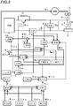
- Fig. 3 is a block diagram illustrating a welding power supply for implementing an arc welding control method according to the second embodiment of the present invention.
- This figure corresponds to Fig. 1 , and blocks identical to those of Fig. 1 are referred to by the same symbols, with explanation thereof being omitted.
- a constriction detection-time setting circuit TNR is added to Fig. 1
- the constriction detection-sensitivity setting circuit NTR of Fig. 1 is replaced by a gain setting circuit GR
- a constriction detection-sensitivity automatic setting control circuit NTC is added to Fig. 1 .
- these individual blocks will be explained with reference to this figure.
- the constriction detection-time setting circuit TNR outputs a predetermined constriction detection-time setting signal Tnr.
- the constriction detection time Tn is a proper value within a range from 200 to 1,000 ⁇ s.
- the constriction detection-time setting signal Tnr is set to 500 ⁇ , for example.
- the gain setting circuit GR calculates a gain standard value Gs according to a predetermined gain calculation function based on the average feeding-rate setting signal Far. Then the gain setting circuit corrects the gain standard value Gs using individual values of the amplitude fine-adjustment signal Wfr, the cycle fine-adjustment signal Tfr and the forward/reverse ratio fine-adjustment signal Dfr, and outputs the corrected value as a gain setting signal Gr. This correction is performed according to the following expression.
- the gain standard value Gs is corrected to reduce the gain when the amplitude fine-adjustment signal Wfr has a positive value, whilst corrected to increase the gain when this signal has a negative value.
- the gain standard value Gs is corrected to reduce the gain when the cycle fine-adjustment signal Tfr has a positive value, whilst corrected to increase the gain when this signal has a negative value.
- the gain standard value Gs is corrected to reduce the gain when the forward/reverse ratio fine-adjustment signal Dfr has a positive value, whilst corrected to increase the gain when this signal has a negative value.
- Nt0 is a predetermined initial value.
- a value of the constriction detection-sensitivity setting signal Ntr is controlled so as to be automatically set to a suitable value so that the constriction detection time Tn becomes equal to a value of the constriction detection-time setting signal Tnr.
- a timing chart of individual signals in the welding power supply of Fig. 3 for explaining the arc welding control method according to the second embodiment of the present invention is same as that of Fig. 2 , and hence the explanation thereof is omitted.
- the timing chart in this embodiment differs from Fig. 2 in a point that a value of the constriction detection-sensitivity setting signal Ntr, for determining a timing at which the constriction detection signal Nd shown in (D) of Fig. 2 becomes the high level, is controlled so as to be automatically set to a suitable value.
- the timing chart in this embodiment differs from Fig. 2 in a point that a value of the gain setting signal Gr for the automatic setting control changes to a suitable value according to the change of the waveform parameter of feeding rate Fw so that stability of the control system is maintained even if the waveform parameter of feeding rate Fw changes.
- the detection sensitivity of constriction is subjected to the automatic setting control based on the constriction detection time representing the time period from the time point where a constriction is detected during the short-circuiting period to the time point where shifting to the arc period is performed, and a gain for the automatic setting control is changed according to the waveform parameter of feeding rate
- the waveform parameter of feeding rate such as an amplitude, a cycle or a ratio between the forward feeding period and the reverse feeding period changes
- a gain for subjecting the detection sensitivity of constriction to the automatic setting control is optimized. Consequently even if the waveform parameter of feeding rate changes, as the detection sensitivity of constriction is optimized, the constriction detection control can be suppressed becoming unstable.
- the constriction detection control can be suppressed becoming unstable.
Landscapes
- Engineering & Computer Science (AREA)
- Physics & Mathematics (AREA)
- Plasma & Fusion (AREA)
- Mechanical Engineering (AREA)
- Arc Welding Control (AREA)
Applications Claiming Priority (2)
| Application Number | Priority Date | Filing Date | Title |
|---|---|---|---|
| JP2014103477 | 2014-05-19 | ||
| PCT/JP2015/062700 WO2015178170A1 (fr) | 2014-05-19 | 2015-04-27 | Procédé de commande de soudage à l'arc |
Publications (3)
| Publication Number | Publication Date |
|---|---|
| EP3147064A1 true EP3147064A1 (fr) | 2017-03-29 |
| EP3147064A4 EP3147064A4 (fr) | 2018-01-24 |
| EP3147064B1 EP3147064B1 (fr) | 2020-12-09 |
Family
ID=54553845
Family Applications (1)
| Application Number | Title | Priority Date | Filing Date |
|---|---|---|---|
| EP15795407.4A Not-in-force EP3147064B1 (fr) | 2014-05-19 | 2015-04-27 | Procédé de commande de soudage à l'arc |
Country Status (6)
| Country | Link |
|---|---|
| US (1) | US10391578B2 (fr) |
| EP (1) | EP3147064B1 (fr) |
| JP (1) | JP6555825B2 (fr) |
| KR (1) | KR102284586B1 (fr) |
| CN (1) | CN106029282B (fr) |
| WO (1) | WO2015178170A1 (fr) |
Families Citing this family (5)
| Publication number | Priority date | Publication date | Assignee | Title |
|---|---|---|---|---|
| JP6555825B2 (ja) * | 2014-05-19 | 2019-08-07 | 株式会社ダイヘン | アーク溶接制御方法 |
| FI3569340T3 (fi) | 2017-01-16 | 2024-05-14 | Daihen Corp | Kaaren alkamisen ohjausmenetelmä eteen- ja taaksepäinsyöttökaarihitsausta varten |
| JP7017979B2 (ja) * | 2018-04-26 | 2022-02-09 | 株式会社神戸製鋼所 | 溶接電源および溶接電源の制御方法 |
| JP7272740B2 (ja) * | 2019-05-07 | 2023-05-12 | 株式会社ダイヘン | アーク溶接制御方法 |
| JP7576504B2 (ja) | 2021-04-16 | 2024-10-31 | 株式会社ダイヘン | アーク溶接装置 |
Family Cites Families (19)
| Publication number | Priority date | Publication date | Assignee | Title |
|---|---|---|---|---|
| AT282707B (de) | 1967-07-18 | 1970-07-10 | Philips Nv | Elektronenstrahlröhre mit einer Elektronenstrahlquelle zum Erzeugen mehrerer Elektronenbündel |
| IT1038966B (it) | 1975-06-12 | 1979-11-30 | Itw Fastex Italia Spa | Madrevite in materiale plastico funzionante da tassello |
| JP4907892B2 (ja) | 2005-03-31 | 2012-04-04 | 株式会社ダイヘン | 消耗電極アーク溶接のくびれ検出制御方法 |
| JP5038206B2 (ja) | 2007-11-26 | 2012-10-03 | 株式会社ダイヘン | 消耗電極アーク溶接のくびれ検出制御方法 |
| WO2011013305A1 (fr) * | 2009-07-29 | 2011-02-03 | パナソニック株式会社 | Procédé de soudage à l'arc et dispositif de soudage à l'arc |
| US8993925B2 (en) * | 2009-07-29 | 2015-03-31 | Panasonic Intellectual Property Management Co., Ltd. | Arc welding method and arc welding apparatus |
| JP5370089B2 (ja) | 2009-11-06 | 2013-12-18 | パナソニック株式会社 | アーク溶接方法およびアーク溶接装置 |
| CN102380691B (zh) | 2010-08-31 | 2014-11-05 | 株式会社大亨 | 消耗电极电弧焊接的缩颈检测控制方法 |
| JP5801058B2 (ja) * | 2011-02-07 | 2015-10-28 | 株式会社ダイヘン | 溶接装置および炭酸ガスアーク溶接方法 |
| JP5808947B2 (ja) * | 2011-05-23 | 2015-11-10 | 株式会社ダイヘン | 消耗電極アーク溶接のくびれ検出制御方法 |
| JP6089231B2 (ja) * | 2012-06-18 | 2017-03-08 | パナソニックIpマネジメント株式会社 | アーク溶接方法およびアーク溶接装置 |
| JP2014030831A (ja) * | 2012-08-01 | 2014-02-20 | Daihen Corp | 消耗電極アーク溶接制御方法 |
| US20140039937A1 (en) * | 2012-08-03 | 2014-02-06 | Cloudbridge, Llc | Insurance Data Management System |
| JP2014039937A (ja) * | 2012-08-21 | 2014-03-06 | Daihen Corp | 消耗電極アーク溶接制御方法 |
| EP3187295B1 (fr) * | 2012-10-01 | 2020-06-03 | Panasonic Intellectual Property Management Co., Ltd. | Procédé de commande de soudage à l'arc |
| CN104582888B (zh) * | 2012-11-07 | 2016-08-17 | 松下知识产权经营株式会社 | 电弧焊接装置以及电弧焊接控制方法 |
| JP6134601B2 (ja) * | 2013-07-23 | 2017-05-24 | 株式会社ダイヘン | 溶接電源のくびれ検出制御方法 |
| JP6023991B2 (ja) * | 2014-02-14 | 2016-11-09 | パナソニックIpマネジメント株式会社 | アーク溶接方法 |
| JP6555825B2 (ja) * | 2014-05-19 | 2019-08-07 | 株式会社ダイヘン | アーク溶接制御方法 |
-
2015
- 2015-04-27 JP JP2016521015A patent/JP6555825B2/ja active Active
- 2015-04-27 CN CN201580009849.8A patent/CN106029282B/zh not_active Expired - Fee Related
- 2015-04-27 WO PCT/JP2015/062700 patent/WO2015178170A1/fr not_active Ceased
- 2015-04-27 US US15/303,295 patent/US10391578B2/en active Active
- 2015-04-27 KR KR1020167023337A patent/KR102284586B1/ko not_active Expired - Fee Related
- 2015-04-27 EP EP15795407.4A patent/EP3147064B1/fr not_active Not-in-force
Also Published As
| Publication number | Publication date |
|---|---|
| KR102284586B1 (ko) | 2021-07-30 |
| EP3147064B1 (fr) | 2020-12-09 |
| JP6555825B2 (ja) | 2019-08-07 |
| CN106029282A (zh) | 2016-10-12 |
| US20170028502A1 (en) | 2017-02-02 |
| KR20170003907A (ko) | 2017-01-10 |
| CN106029282B (zh) | 2019-10-18 |
| WO2015178170A1 (fr) | 2015-11-26 |
| JPWO2015178170A1 (ja) | 2017-04-20 |
| EP3147064A4 (fr) | 2018-01-24 |
| US10391578B2 (en) | 2019-08-27 |
Similar Documents
| Publication | Publication Date | Title |
|---|---|---|
| EP3117944B1 (fr) | Procédé de commande de soudage à l'arc | |
| EP3095546B1 (fr) | Procédé de commande de soudage à l'arc | |
| EP3147064B1 (fr) | Procédé de commande de soudage à l'arc | |
| EP3108989B1 (fr) | Alimentation pour le soudage à l'arc | |
| EP3093093B1 (fr) | Procédé de commande de soudage à l'arc | |
| EP3135420B1 (fr) | Procede de commande de soudage a l'arc | |
| EP3184227B1 (fr) | Procédé de commande de soudage à l'arc | |
| EP3120963B1 (fr) | Procédé de commande de soudage à l'arc | |
| JP2015231632A (ja) | アーク溶接制御方法 | |
| JP6377427B2 (ja) | アーク溶接制御方法 | |
| JP6341610B2 (ja) | アーク溶接制御方法 |
Legal Events
| Date | Code | Title | Description |
|---|---|---|---|
| STAA | Information on the status of an ep patent application or granted ep patent |
Free format text: STATUS: THE INTERNATIONAL PUBLICATION HAS BEEN MADE |
|
| PUAI | Public reference made under article 153(3) epc to a published international application that has entered the european phase |
Free format text: ORIGINAL CODE: 0009012 |
|
| STAA | Information on the status of an ep patent application or granted ep patent |
Free format text: STATUS: REQUEST FOR EXAMINATION WAS MADE |
|
| 17P | Request for examination filed |
Effective date: 20161118 |
|
| AK | Designated contracting states |
Kind code of ref document: A1 Designated state(s): AL AT BE BG CH CY CZ DE DK EE ES FI FR GB GR HR HU IE IS IT LI LT LU LV MC MK MT NL NO PL PT RO RS SE SI SK SM TR |
|
| AX | Request for extension of the european patent |
Extension state: BA ME |
|
| DAV | Request for validation of the european patent (deleted) | ||
| DAX | Request for extension of the european patent (deleted) | ||
| A4 | Supplementary search report drawn up and despatched |
Effective date: 20171222 |
|
| RIC1 | Information provided on ipc code assigned before grant |
Ipc: B23K 9/073 20060101AFI20171218BHEP Ipc: B23K 9/12 20060101ALI20171218BHEP |
|
| GRAP | Despatch of communication of intention to grant a patent |
Free format text: ORIGINAL CODE: EPIDOSNIGR1 |
|
| STAA | Information on the status of an ep patent application or granted ep patent |
Free format text: STATUS: GRANT OF PATENT IS INTENDED |
|
| INTG | Intention to grant announced |
Effective date: 20200715 |
|
| GRAS | Grant fee paid |
Free format text: ORIGINAL CODE: EPIDOSNIGR3 |
|
| GRAA | (expected) grant |
Free format text: ORIGINAL CODE: 0009210 |
|
| STAA | Information on the status of an ep patent application or granted ep patent |
Free format text: STATUS: THE PATENT HAS BEEN GRANTED |
|
| AK | Designated contracting states |
Kind code of ref document: B1 Designated state(s): AL AT BE BG CH CY CZ DE DK EE ES FI FR GB GR HR HU IE IS IT LI LT LU LV MC MK MT NL NO PL PT RO RS SE SI SK SM TR |
|
| REG | Reference to a national code |
Ref country code: GB Ref legal event code: FG4D |
|
| REG | Reference to a national code |
Ref country code: AT Ref legal event code: REF Ref document number: 1342910 Country of ref document: AT Kind code of ref document: T Effective date: 20201215 Ref country code: CH Ref legal event code: EP |
|
| REG | Reference to a national code |
Ref country code: DE Ref legal event code: R096 Ref document number: 602015063304 Country of ref document: DE |
|
| REG | Reference to a national code |
Ref country code: IE Ref legal event code: FG4D |
|
| PG25 | Lapsed in a contracting state [announced via postgrant information from national office to epo] |
Ref country code: RS Free format text: LAPSE BECAUSE OF FAILURE TO SUBMIT A TRANSLATION OF THE DESCRIPTION OR TO PAY THE FEE WITHIN THE PRESCRIBED TIME-LIMIT Effective date: 20201209 Ref country code: FI Free format text: LAPSE BECAUSE OF FAILURE TO SUBMIT A TRANSLATION OF THE DESCRIPTION OR TO PAY THE FEE WITHIN THE PRESCRIBED TIME-LIMIT Effective date: 20201209 Ref country code: NO Free format text: LAPSE BECAUSE OF FAILURE TO SUBMIT A TRANSLATION OF THE DESCRIPTION OR TO PAY THE FEE WITHIN THE PRESCRIBED TIME-LIMIT Effective date: 20210309 Ref country code: GR Free format text: LAPSE BECAUSE OF FAILURE TO SUBMIT A TRANSLATION OF THE DESCRIPTION OR TO PAY THE FEE WITHIN THE PRESCRIBED TIME-LIMIT Effective date: 20210310 |
|
| REG | Reference to a national code |
Ref country code: AT Ref legal event code: MK05 Ref document number: 1342910 Country of ref document: AT Kind code of ref document: T Effective date: 20201209 |
|
| PG25 | Lapsed in a contracting state [announced via postgrant information from national office to epo] |
Ref country code: LV Free format text: LAPSE BECAUSE OF FAILURE TO SUBMIT A TRANSLATION OF THE DESCRIPTION OR TO PAY THE FEE WITHIN THE PRESCRIBED TIME-LIMIT Effective date: 20201209 Ref country code: SE Free format text: LAPSE BECAUSE OF FAILURE TO SUBMIT A TRANSLATION OF THE DESCRIPTION OR TO PAY THE FEE WITHIN THE PRESCRIBED TIME-LIMIT Effective date: 20201209 Ref country code: BG Free format text: LAPSE BECAUSE OF FAILURE TO SUBMIT A TRANSLATION OF THE DESCRIPTION OR TO PAY THE FEE WITHIN THE PRESCRIBED TIME-LIMIT Effective date: 20210309 |
|
| REG | Reference to a national code |
Ref country code: NL Ref legal event code: MP Effective date: 20201209 |
|
| PG25 | Lapsed in a contracting state [announced via postgrant information from national office to epo] |
Ref country code: NL Free format text: LAPSE BECAUSE OF FAILURE TO SUBMIT A TRANSLATION OF THE DESCRIPTION OR TO PAY THE FEE WITHIN THE PRESCRIBED TIME-LIMIT Effective date: 20201209 Ref country code: HR Free format text: LAPSE BECAUSE OF FAILURE TO SUBMIT A TRANSLATION OF THE DESCRIPTION OR TO PAY THE FEE WITHIN THE PRESCRIBED TIME-LIMIT Effective date: 20201209 |
|
| REG | Reference to a national code |
Ref country code: LT Ref legal event code: MG9D |
|
| PG25 | Lapsed in a contracting state [announced via postgrant information from national office to epo] |
Ref country code: SK Free format text: LAPSE BECAUSE OF FAILURE TO SUBMIT A TRANSLATION OF THE DESCRIPTION OR TO PAY THE FEE WITHIN THE PRESCRIBED TIME-LIMIT Effective date: 20201209 Ref country code: RO Free format text: LAPSE BECAUSE OF FAILURE TO SUBMIT A TRANSLATION OF THE DESCRIPTION OR TO PAY THE FEE WITHIN THE PRESCRIBED TIME-LIMIT Effective date: 20201209 Ref country code: PT Free format text: LAPSE BECAUSE OF FAILURE TO SUBMIT A TRANSLATION OF THE DESCRIPTION OR TO PAY THE FEE WITHIN THE PRESCRIBED TIME-LIMIT Effective date: 20210409 Ref country code: LT Free format text: LAPSE BECAUSE OF FAILURE TO SUBMIT A TRANSLATION OF THE DESCRIPTION OR TO PAY THE FEE WITHIN THE PRESCRIBED TIME-LIMIT Effective date: 20201209 Ref country code: EE Free format text: LAPSE BECAUSE OF FAILURE TO SUBMIT A TRANSLATION OF THE DESCRIPTION OR TO PAY THE FEE WITHIN THE PRESCRIBED TIME-LIMIT Effective date: 20201209 Ref country code: CZ Free format text: LAPSE BECAUSE OF FAILURE TO SUBMIT A TRANSLATION OF THE DESCRIPTION OR TO PAY THE FEE WITHIN THE PRESCRIBED TIME-LIMIT Effective date: 20201209 Ref country code: SM Free format text: LAPSE BECAUSE OF FAILURE TO SUBMIT A TRANSLATION OF THE DESCRIPTION OR TO PAY THE FEE WITHIN THE PRESCRIBED TIME-LIMIT Effective date: 20201209 |
|
| PG25 | Lapsed in a contracting state [announced via postgrant information from national office to epo] |
Ref country code: AT Free format text: LAPSE BECAUSE OF FAILURE TO SUBMIT A TRANSLATION OF THE DESCRIPTION OR TO PAY THE FEE WITHIN THE PRESCRIBED TIME-LIMIT Effective date: 20201209 Ref country code: PL Free format text: LAPSE BECAUSE OF FAILURE TO SUBMIT A TRANSLATION OF THE DESCRIPTION OR TO PAY THE FEE WITHIN THE PRESCRIBED TIME-LIMIT Effective date: 20201209 |
|
| REG | Reference to a national code |
Ref country code: DE Ref legal event code: R097 Ref document number: 602015063304 Country of ref document: DE |
|
| PG25 | Lapsed in a contracting state [announced via postgrant information from national office to epo] |
Ref country code: IS Free format text: LAPSE BECAUSE OF FAILURE TO SUBMIT A TRANSLATION OF THE DESCRIPTION OR TO PAY THE FEE WITHIN THE PRESCRIBED TIME-LIMIT Effective date: 20210409 |
|
| PLBE | No opposition filed within time limit |
Free format text: ORIGINAL CODE: 0009261 |
|
| STAA | Information on the status of an ep patent application or granted ep patent |
Free format text: STATUS: NO OPPOSITION FILED WITHIN TIME LIMIT |
|
| PG25 | Lapsed in a contracting state [announced via postgrant information from national office to epo] |
Ref country code: IT Free format text: LAPSE BECAUSE OF FAILURE TO SUBMIT A TRANSLATION OF THE DESCRIPTION OR TO PAY THE FEE WITHIN THE PRESCRIBED TIME-LIMIT Effective date: 20201209 Ref country code: AL Free format text: LAPSE BECAUSE OF FAILURE TO SUBMIT A TRANSLATION OF THE DESCRIPTION OR TO PAY THE FEE WITHIN THE PRESCRIBED TIME-LIMIT Effective date: 20201209 |
|
| 26N | No opposition filed |
Effective date: 20210910 |
|
| PG25 | Lapsed in a contracting state [announced via postgrant information from national office to epo] |
Ref country code: SI Free format text: LAPSE BECAUSE OF FAILURE TO SUBMIT A TRANSLATION OF THE DESCRIPTION OR TO PAY THE FEE WITHIN THE PRESCRIBED TIME-LIMIT Effective date: 20201209 Ref country code: MC Free format text: LAPSE BECAUSE OF FAILURE TO SUBMIT A TRANSLATION OF THE DESCRIPTION OR TO PAY THE FEE WITHIN THE PRESCRIBED TIME-LIMIT Effective date: 20201209 Ref country code: ES Free format text: LAPSE BECAUSE OF FAILURE TO SUBMIT A TRANSLATION OF THE DESCRIPTION OR TO PAY THE FEE WITHIN THE PRESCRIBED TIME-LIMIT Effective date: 20201209 Ref country code: DK Free format text: LAPSE BECAUSE OF FAILURE TO SUBMIT A TRANSLATION OF THE DESCRIPTION OR TO PAY THE FEE WITHIN THE PRESCRIBED TIME-LIMIT Effective date: 20201209 |
|
| PG25 | Lapsed in a contracting state [announced via postgrant information from national office to epo] |
Ref country code: LU Free format text: LAPSE BECAUSE OF NON-PAYMENT OF DUE FEES Effective date: 20210427 |
|
| REG | Reference to a national code |
Ref country code: BE Ref legal event code: MM Effective date: 20210430 |
|
| PG25 | Lapsed in a contracting state [announced via postgrant information from national office to epo] |
Ref country code: CH Free format text: LAPSE BECAUSE OF NON-PAYMENT OF DUE FEES Effective date: 20210430 Ref country code: LI Free format text: LAPSE BECAUSE OF NON-PAYMENT OF DUE FEES Effective date: 20210430 Ref country code: FR Free format text: LAPSE BECAUSE OF NON-PAYMENT OF DUE FEES Effective date: 20210430 |
|
| PG25 | Lapsed in a contracting state [announced via postgrant information from national office to epo] |
Ref country code: IE Free format text: LAPSE BECAUSE OF NON-PAYMENT OF DUE FEES Effective date: 20210427 |
|
| PG25 | Lapsed in a contracting state [announced via postgrant information from national office to epo] |
Ref country code: IS Free format text: LAPSE BECAUSE OF FAILURE TO SUBMIT A TRANSLATION OF THE DESCRIPTION OR TO PAY THE FEE WITHIN THE PRESCRIBED TIME-LIMIT Effective date: 20210409 |
|
| PG25 | Lapsed in a contracting state [announced via postgrant information from national office to epo] |
Ref country code: BE Free format text: LAPSE BECAUSE OF NON-PAYMENT OF DUE FEES Effective date: 20210430 |
|
| PG25 | Lapsed in a contracting state [announced via postgrant information from national office to epo] |
Ref country code: HU Free format text: LAPSE BECAUSE OF FAILURE TO SUBMIT A TRANSLATION OF THE DESCRIPTION OR TO PAY THE FEE WITHIN THE PRESCRIBED TIME-LIMIT; INVALID AB INITIO Effective date: 20150427 |
|
| PG25 | Lapsed in a contracting state [announced via postgrant information from national office to epo] |
Ref country code: CY Free format text: LAPSE BECAUSE OF FAILURE TO SUBMIT A TRANSLATION OF THE DESCRIPTION OR TO PAY THE FEE WITHIN THE PRESCRIBED TIME-LIMIT Effective date: 20201209 |
|
| PG25 | Lapsed in a contracting state [announced via postgrant information from national office to epo] |
Ref country code: MK Free format text: LAPSE BECAUSE OF FAILURE TO SUBMIT A TRANSLATION OF THE DESCRIPTION OR TO PAY THE FEE WITHIN THE PRESCRIBED TIME-LIMIT Effective date: 20201209 |
|
| PGFP | Annual fee paid to national office [announced via postgrant information from national office to epo] |
Ref country code: GB Payment date: 20240307 Year of fee payment: 10 |
|
| PG25 | Lapsed in a contracting state [announced via postgrant information from national office to epo] |
Ref country code: TR Free format text: LAPSE BECAUSE OF FAILURE TO SUBMIT A TRANSLATION OF THE DESCRIPTION OR TO PAY THE FEE WITHIN THE PRESCRIBED TIME-LIMIT Effective date: 20201209 |
|
| PGFP | Annual fee paid to national office [announced via postgrant information from national office to epo] |
Ref country code: DE Payment date: 20240306 Year of fee payment: 10 |
|
| PG25 | Lapsed in a contracting state [announced via postgrant information from national office to epo] |
Ref country code: MT Free format text: LAPSE BECAUSE OF FAILURE TO SUBMIT A TRANSLATION OF THE DESCRIPTION OR TO PAY THE FEE WITHIN THE PRESCRIBED TIME-LIMIT Effective date: 20201209 |
|
| REG | Reference to a national code |
Ref country code: DE Ref legal event code: R119 Ref document number: 602015063304 Country of ref document: DE |
|
| GBPC | Gb: european patent ceased through non-payment of renewal fee |
Effective date: 20250427 |
|
| PG25 | Lapsed in a contracting state [announced via postgrant information from national office to epo] |
Ref country code: DE Free format text: LAPSE BECAUSE OF NON-PAYMENT OF DUE FEES Effective date: 20251104 |
|
| PG25 | Lapsed in a contracting state [announced via postgrant information from national office to epo] |
Ref country code: GB Free format text: LAPSE BECAUSE OF NON-PAYMENT OF DUE FEES Effective date: 20250427 |