EP3147082B1 - Driving tool - Google Patents
Driving tool Download PDFInfo
- Publication number
- EP3147082B1 EP3147082B1 EP16001846.1A EP16001846A EP3147082B1 EP 3147082 B1 EP3147082 B1 EP 3147082B1 EP 16001846 A EP16001846 A EP 16001846A EP 3147082 B1 EP3147082 B1 EP 3147082B1
- Authority
- EP
- European Patent Office
- Prior art keywords
- head valve
- cylinder
- lip portion
- seal
- compressed air
- Prior art date
- Legal status (The legal status is an assumption and is not a legal conclusion. Google has not performed a legal analysis and makes no representation as to the accuracy of the status listed.)
- Active
Links
Images



Classifications
-
- B—PERFORMING OPERATIONS; TRANSPORTING
- B25—HAND TOOLS; PORTABLE POWER-DRIVEN TOOLS; MANIPULATORS
- B25C—HAND-HELD NAILING OR STAPLING TOOLS; MANUALLY OPERATED PORTABLE STAPLING TOOLS
- B25C1/00—Hand-held nailing tools; Nail feeding devices
- B25C1/04—Hand-held nailing tools; Nail feeding devices operated by fluid pressure, e.g. by air pressure
- B25C1/047—Mechanical details
-
- B—PERFORMING OPERATIONS; TRANSPORTING
- B25—HAND TOOLS; PORTABLE POWER-DRIVEN TOOLS; MANIPULATORS
- B25C—HAND-HELD NAILING OR STAPLING TOOLS; MANUALLY OPERATED PORTABLE STAPLING TOOLS
- B25C1/00—Hand-held nailing tools; Nail feeding devices
- B25C1/04—Hand-held nailing tools; Nail feeding devices operated by fluid pressure, e.g. by air pressure
- B25C1/041—Hand-held nailing tools; Nail feeding devices operated by fluid pressure, e.g. by air pressure with fixed main cylinder
- B25C1/042—Main valve and main cylinder
Definitions
- the present disclosure relates to a driving tool which operates a piston by compressed air to drive out a fastener, and particularly to a driving tool which prevents air leakage of a head valve.
- a tool including a head valve which controls a flow of compressed air into a cylinder.
- the head valve When a trigger of the driving tool is manipulated, the head valve is operated to open a supply passage into the cylinder. Accordingly, the compressed air flows into the cylinder to operate a piston, and thus a fastener is driven. At this time, an exhaust passage communicating with the inside of the cylinder is closed by the head valve.
- the driving is completed, and the head valve returns to an initial position, the supply passage into the cylinder is closed, and the exhaust passage communicating with the inside of the cylinder is opened to discharge the compressed air in the cylinder.
- JP-B Japanese Patent Publication
- JP-B No. 4706604
- the description is given about a technology having a structure that the leg portion extending from the outer circumference of the head bumper has a ring-shaped seal member extending toward the main valve (head valve), and the seal member performs sealing by contacting the inner wall surface of the main valve.
- the seal member extending toward the head valve is provided so that the timing when the supply passage is opened can be set close to the timing when the exhaust passage is closed and the leakage of the compressed air into the exhaust passage can be suppressed.
- an object of the disclosure is to provide a driving tool, in which the exhaust passage is closed after the supply passage into a cylinder is opened, and in which it is suppressed that compressed air leaks from an exhaust passage after a supply passage is opened and it is not necessary to severely manage a dimension in producing.
- the disclosure has been made to resolve the above-described problem, and has the following features.
- An aspect of the disclosure is to provide a driving tool including:
- the lip portion may protrude with a clearance provided between the lip portion and the outer circumferential surface of the head valve.
- an air pressure difference may be generated between an inside and an outside of the lip portion, and the lip portion may be bent in a direction of contacting the outer circumferential surface of the head valve.
- a tapered surface may be formed on an inner circumferential side of a tip of the lip portion or an outer circumferential side of an opening edge of the head valve.
- a seal member may be mounted to any one of the head valve and the cylinder, a receiving portion facing the seal member may be provided in the other one of the head valve and the cylinder, the receiving portion may include a seal surface formed obliquely to a sliding direction of the head valve, and an exhaust passage formed between the cylinder and the head valve may be sealed by the seal member contacting with the seal surface.
- the seal portion is provided to face the opening edge of the head valve, and the seal portion includes the lip portion protruding along the outer circumferential surface of the head valve.
- the lip portion protrudes with the clearance provided between the lip portion and the outer circumferential surface of the head valve.
- the clearance is provided in advance between the lip portion and the outer circumferential surface of the head valve, and thus a slide resistance with the head valve does not increase although there is a slight dimension change in the seal portion. That is, the slide resistance does not increase although the dimension is not severely managed.
- the driving tool of the disclosure when the head valve slides in the direction of separating from the seal portion, the air pressure difference is generated between the inside and the outside of the lip portion, and the lip portion is bent in the direction of contacting the outer circumferential surface of the head valve. That is, the lip portion protrudes along the outer circumferential surface of the head valve, and thus in starting the movement of the head valve, the lip portion is deformed by the air pressure difference, and contacts the head valve. For this reason, the lip portion seals the supply passage although the clearance is provided, and thus the timing when the supply passage is completely opened can be delayed.
- the time difference between the timing when the supply passage is opened and the timing when the exhaust passage is closed is shortened by delaying the timing when the supply passage is completely opened, and thus the leakage of the compressed air from the exhaust passage can be suppressed.
- the tapered surface is formed on the inner circumferential side of the tip of the lip portion or the outer circumferential side of the opening edge of the head valve.
- the seal member is mounted in any one of the head valve and the cylinder, the receiving portion facing the seal member is provided in the other one the head valve and the cylinder, and the receiving portion includes the seal surface formed obliquely to the sliding direction of the head valve.
- the exhaust passage formed between the cylinder and the head valve is sealed by contacting the seal member with the seal surface.
- the head valve is smoothly slid so that the time until the exhaust passage is sealed is shortened, and thus the time difference between the timing when the supply passage is opened and the timing when the exhaust passage is closed is shortened so that the leakage of the compressed air from the exhaust passage can be suppressed.
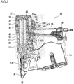
- a driving tool 10 is a pneumatic driving tool 10 which drives a fastener using compressed air.
- the driving tool includes a tool main body 11 having a nose portion 13 and a magazine 19 connected to the tool main body 11.
- a connection fastener is contained in the magazine 19, and the connection fastener is pulled out in a direction of the nose portion 13 and used for driving.
- the tool main body 11 includes a body housing 12, a grip housing 16 connected to the body housing 12 at a substantially perpendicular angle, the nose portion 13 integrally fixed to the front end side (a driving direction of the fastener) of the body housing 12, and a cap housing 20 integrally fixed to the rear end side (an opposite direction to the driving direction of the fastener) of the body housing 12.
- a cylinder 31 is disposed inside the body housing 12 and the cap housing 20, and a piston 32 is contained in the cylinder 31 so as to be reciprocated.
- a driver 33 for striking the fastener is coupled with the lower surface of the piston 32.
- the driver 33 is moved downward integrally with the piston 32 to drive the fastener.
- the compressed air for operating the piston 32 is supplied from an external device such as an air compressor.
- an external device is connected to an end cap portion 18 provided in a rear end of the grip housing 16. The compressed air supplied from the external device can pass into the grip housing 16 and be supplied to the cylinder 31.
- the nose portion 13 is provided to inject the fastener, and the above-described driver 33 is guided to be slidable in the direction of the nose portion 13.
- a fastener supply mechanism is provided on the rear side of the nose portion 13. The feeding operation of the fastener supply mechanism is executed in conjunction with the driving operation. The fastener contained in the magazine 19 is fed to the nose portion 13 through the feeding operation.
- a contact portion 14 pushed against a target material to be driven is mounted in the tip of the nose portion 13 so as to be slidable on the nose portion 13.
- the contact portion 14 is slid upward on the nose portion 13 when pushed against the target material to be driven, and such a slide of the contact portion 14 causes a safety mechanism of the driving operation to operate. While not describing the well-known safety mechanism in detail, the operation of the safety mechanism enables to manipulate a trigger 17 provided with the grip housing 16 and to drive the fastener.
- the compressed air supplied from the external device flows into the cylinder 31, and the compressed air acts on the piston 32 to run the piston 32.
- the piston 32 runs so that the driver 33 coupled to the piston 32 strikes a first fastener, and the fastener is driven out.
- An injection port 15 through which the fastener is driven out is formed at the tip of the contact portion 14, and the inner circumferential surface of the contact portion 14 until the injection port 15 forms an injection passage of the fastener.
- the driving tool 10 inwardly includes a head valve 34 which controls the flow of the compressed air into the cylinder 31, a piston stop 35 which stops the piston 32 at a top dead point, a cylindrical guide 36 which supports the circumferential edge of the piston stop 35, a sweeper member 37 which is fixed by the cylindrical guide 36, a main chamber 41 which stores the compressed air for biasing the piston 32, a main exhaust passage 42 configured to discharges the compressed air flowing into the cylinder 31 to the outside, a head valve chamber 46 which stores the compressed air for biasing the head valve 34, a sub exhaust passage 47 configured to discharge the compressed air stored in the head valve chamber 46 to the outside, and a pilot valve 40 configured to open and close the head valve chamber 46 to an atmosphere side.
- a head valve 34 which controls the flow of the compressed air into the cylinder 31
- a piston stop 35 which stops the piston 32 at a top dead point
- a cylindrical guide 36 which supports the circumferential edge of the piston stop 35
- a sweeper member 37 which is fixed by the cylindrical guide 36
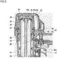
- the head valve 34 is a cylindrical member disposed on the outside of the cylinder 31, and is slidable in an axial direction to the cylinder 31. As illustrated in Fig. 3 , the head valve 34 is pushed upward by the compressed air stored in the head valve chamber 46 and by a compression spring in a state where the pilot valve 40 is not operated (in a state where the trigger 17 is not manipulated). At this time, the force of pushing downward by the compressed air of the main chamber 41 acts on the head valve 34. However, since an area where the compressed air acts on the head valve chamber 46 side is larger than that on the main chamber 41 side, the head valve 34 is pushed upward by the differential pressure.
- the piston stop 35 is configured to receive and stop the piston 32 moved to the top dead point, and is fixed on a ceiling portion of the cap housing 20.
- the piston stop 35 is formed, for example, of an elastic material such as rubber in order to receive an impact of the piston 32.
- the seal portion 35a configured to seal the circumference of the cylinder 31 by being coupled with the head valve 34 is formed in the vicinity of the outer circumferential edge of the piston stop 35.
- the cylindrical guide 36 is a member for supporting the vicinity of the outer circumferential edge of the piston stop 35, and supports the substantially outer circumferential side of the seal portion 35a to prevent the piston stop 35 from being hung down.
- the cylindrical guide 36 is not intended for the sealing of the compressed air, and thus a plurality of vent holes are drilled in the outer circumference thereof.
- the sweeper member 37 is a ring-shaped member fixed so as to face the circumferential surface of the head valve 34. When the head valve 34 is slid, the sweeper member 37 acts to rub the circumferential surface of the head valve 34, and thus ice and the like attached to the surface of the head valve 34 is scraped off.
- the main chamber 41 is a space configured to store the compressed air supplied from the external device such as the compressor.
- the main chamber 41 always receives the compressed air from the external device connected to the end cap portion 18.
- the main exhaust passage 42 discharges the compressed air in the cylinder 31 to the outside.
- the main exhaust passage 42 is provided to communicate with an exhaust hole 34a formed in the outer circumference of the head valve 34. Accordingly, the compressed air in the cylinder 31 is introduced to the main exhaust passage 42 through the exhaust hole 34a of the head valve 34, and is discharged to the outside.
- a main exhaust chamber (not illustrated) configured to reduce the pressure of the compressed air is provided on the main exhaust passage 42.
- the main exhaust chamber is formed by covering the side portion of the body housing 12 with a resin cover 22.
- a plurality of slits illustrated in Fig. 1 are provided on the surface of the resin cover 22, and the slit forms a discharge port 43b configured to discharge the compressed air of the main exhaust chamber to the outside.
- the head valve chamber 46 is a space configured to store the compressed air for biasing the head valve 34 to a stand-by state.
- the head valve chamber 46 is configured to open and close to external air and the main chamber 41 by the pilot valve 40. That is, as illustrated in Fig. 3 , in a state where the pilot valve 40 is not operated, the head valve chamber 46 communicates with the main chamber 41, and stores the compressed air supplied from the compressor and the like. At this time, the head valve chamber 46 is in the state of being closed to the external air.
- the sub exhaust passage 47 is configured to discharge the compressed air of the head valve chamber 46 to the outside.
- the sub exhaust passage 47 is not connected to the above-described main exhaust passage 42, and is provided independently from the main exhaust passage 42.
- the sub exhaust passage 47 includes a sub exhaust duct 48 connected to the head valve chamber 46, and a sub exhaust chamber 49 provided in the downstream of the sub exhaust duct 48.
- the sub exhaust duct 48 and the sub exhaust chamber 49 are openable and closable by the pilot valve 40.
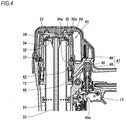
- the seal portion 35a is provided in the piston stop 35 to face the opening edge of the head valve 34.
- the seal portion 35a includes a lip portion 35b protruding along the outer circumferential surface of the head valve 34.
- the lip portion 35b protrudes with a clearance C provided between the lip portion 35b and the outer circumferential surface of the head valve 34.
- a protrusion 35c protruding toward the outer circumferential surface of the head valve 34 is formed on the inner circumferential surface of the lip portion 35b.
- Fig. 7A when the head valve 34 is operated to be slid in a direction of being apart from the seal portion 35a, an air pressure difference is generated between the inside (cylinder 31 side) and the outside (main chamber 41 side) of the lip portion 35b. That is, since the air pressure inside the cylinder 31 is substantially the same as the atmosphere pressure and the main chamber 41 is filled with the compressed air, the air pressure on the outside of the lip portion 35b is higher than that on the inside.
- the protrusion 35c is provided on the inner circumferential surface of the lip portion 35b such that the compressed air is controlled not to flow into the lip portion 35b at once.
- the compressed air, which is used to operate the piston 32, in the cylinder 31 is discharged to the outside through the main exhaust passage 42 as described above. As indicated by an arrow A of Fig. 6A , the discharged air at this time flows to the main exhaust passage 42 through a passage between the cylinder 31 and the head valve 34.
- the passage to the main exhaust passage 42 is formed to be sealable by a seal member 31a mounted in the cylinder 31 and a receiving portion 34b provided in the head valve 34.
- the seal member 31a is an O-ring mounted to the outer circumference of the cylinder 31.
- the receiving portion 34b is provided to face the seal member 31a.
- the receiving portion 34b has a seal surface formed obliquely to a sliding direction of the head valve 34.
- the seal member 31a does not contact the seal surface of the receiving portion 34b in a state where the head valve 34 is not operated, and thus the inside of the cylinder 31 communicates with the main exhaust passage 42. In this manner, in a state where the head valve 34 seals the supply passage into the cylinder 31, an exhaust passage of the compressed air into the cylinder 31 becomes in an opened state.
- the seal portion 35a is provided to face the opening edge of the head valve 34.
- the seal portion 35a includes the lip portion 35b protruding along the outer circumferential surface of the head valve 34, and the lip portion 35b protrudes with the clearance C provided between the lip portion 34 and the outer circumferential surface of the head valve 34.
- the clearance C is provided in advance between the lip portion 35b and the outer circumferential surface of the head valve 34, and thus a slide resistance with the head valve 34 does not increase although there is a slight dimension change in the seal portion 35a. That is, the slide resistance does not increase although the dimension is not severely managed.
- the lip portion 35b When the head valve 34 is slid in the direction of separating from the seal portion 35a, the air pressure difference is generated between the inside and the outside of the lip portion 35b, and thus the lip portion 35b is bent in a direction of contacting the outer circumferential surface of the head valve 34. That is, the lip portion 35b protrudes along the outer circumferential surface of the head valve 34, and thus in starting the movement of the head valve 34, the lip portion 35b is deformed by the air pressure difference, and contacts the head valve 34. For this reason, the lip portion 35b seals the supply passage although the clearance C is provided, and thus the timing when the supply passage is completely opened can be delayed. The time difference between the timing when the supply passage is opened and the timing when the exhaust passage is closed is shortened by delaying the timing when the supply passage is completely opened, and thus the leakage of the compressed air from the exhaust passage can be suppressed.
- the supply passage into the cylinder 31 is sealed by the deformation of the lip portion 35b during the stroke of the head valve 34.
- the lip portion 35b may not contact the head valve 34 when the lip portion 35b is deformed, and the supply passage may not be sealed. Even in such a case, an effect of suppressing the air leakage can be obtained by shortening the gap through the deformation of the lip portion 35b.
- the lip portion 35b does not contact the head valve 34, and thus the increase of the slide resistance between both is suppressed so that the movement of the head valve 34 is smoothly performed. Accordingly, the time until the exhaust passage is sealed is shortened, and thus the leakage of the compressed air from the exhaust passage can be suppressed.
- the seal member 31a is mounted in the cylinder 31, the receiving portion 34b facing the seal member 31a is provided in the head valve 34, the receiving portion 34b includes the seal surface formed obliquely to the sliding direction of the head valve 34, and the seal member 31a contacts the seal surface, thereby sealing the exhaust passage. According to such a configuration, until the seal member 31a contacts the receiving portion 34b, the seal member 31a does not almost contact another member. Therefore, it can be prevented that the seal member 31a increases the slide resistance of the head valve 34, and the head valve 34 can be smoothly slid.
- the head valve 34 is smoothly slid so that the time until the exhaust passage is sealed is shortened, and thus the time difference between the timing when the supply passage is opened and the timing when the exhaust passage is closed is shortened so that the leakage of the compressed air from the exhaust passage can be suppressed.
- the tapered surface is formed on the inner circumferential side of the tip of the lip portion 35b and the outer circumferential side of the opening edge of the head valve 34, and thus the operation can be smoothly performed while the lip portion 35b and the head valve 34 are not caught.
- the seal member 31a is mounted in the cylinder 31, and the receiving portion 34b is provided in the head valve 34.
- the invention is not limited thereto, the seal member 31a may be mounted in the head valve 34, and the receiving portion 34b may be provided in the cylinder 31.
Landscapes
- Physics & Mathematics (AREA)
- Fluid Mechanics (AREA)
- Engineering & Computer Science (AREA)
- Mechanical Engineering (AREA)
- Portable Nailing Machines And Staplers (AREA)
- Compressor (AREA)
Applications Claiming Priority (1)
| Application Number | Priority Date | Filing Date | Title |
|---|---|---|---|
| JP2015165109A JP6578816B2 (ja) | 2015-08-24 | 2015-08-24 | 打込み工具 |
Publications (2)
| Publication Number | Publication Date |
|---|---|
| EP3147082A1 EP3147082A1 (en) | 2017-03-29 |
| EP3147082B1 true EP3147082B1 (en) | 2019-08-14 |
Family
ID=56802200
Family Applications (1)
| Application Number | Title | Priority Date | Filing Date |
|---|---|---|---|
| EP16001846.1A Active EP3147082B1 (en) | 2015-08-24 | 2016-08-23 | Driving tool |
Country Status (6)
| Country | Link |
|---|---|
| US (1) | US10525574B2 (da) |
| EP (1) | EP3147082B1 (da) |
| JP (1) | JP6578816B2 (da) |
| CN (1) | CN106475967B (da) |
| DK (1) | DK3147082T3 (da) |
| TW (1) | TWI678269B (da) |
Families Citing this family (1)
| Publication number | Priority date | Publication date | Assignee | Title |
|---|---|---|---|---|
| JP2025130737A (ja) * | 2024-02-28 | 2025-09-09 | マックス株式会社 | 打ち込み工具 |
Family Cites Families (35)
| Publication number | Priority date | Publication date | Assignee | Title |
|---|---|---|---|---|
| DE2422223A1 (de) * | 1974-05-08 | 1975-11-20 | Reich Maschf Gmbh Karl | Entlueftungsventil fuer druckluftnagler |
| US5131579A (en) * | 1988-03-02 | 1992-07-21 | Max Co., Ltd. | Nailing machine |
| US5207143A (en) * | 1991-05-16 | 1993-05-04 | Umberto Monacelli | Pneumatic fastener driving apparatus with an improved valve |
| US5476205A (en) * | 1994-12-22 | 1995-12-19 | Stanley-Bostitch, Inc. | Make and break head valve assembly |
| EP0747175B1 (en) * | 1995-06-09 | 2003-08-27 | Max Co., Ltd. | Exhaust mechanism of pneumatic nailing machine |
| US5645208A (en) * | 1995-10-17 | 1997-07-08 | Haytayan; Harry M. | Pneumatic fastening tool with safety interlock |
| JP3687593B2 (ja) | 2001-11-19 | 2005-08-24 | マックス株式会社 | 圧縮空気駆動衝撃工具の打撃ピストン保持機構 |
| CN100439042C (zh) | 2003-12-30 | 2008-12-03 | 多系统私人有限公司 | 紧固件推进工具 |
| US20080217372A1 (en) * | 2003-12-30 | 2008-09-11 | Poly Systems Pty Ltd | Fastener Driving Tool |
| JP4214967B2 (ja) * | 2004-02-06 | 2009-01-28 | マックス株式会社 | 部品固定具及びこの部品固定具の釘打機に対する仮保持機構 |
| TW200600288A (en) * | 2004-02-20 | 2006-01-01 | Black & Decker Inc | Adjustable exhaust system for pneumatic nailers and staplers |
| JP4650610B2 (ja) * | 2004-08-19 | 2011-03-16 | マックス株式会社 | 圧縮空気釘打機のメインバルブ機構 |
| JP4923461B2 (ja) * | 2005-07-20 | 2012-04-25 | マックス株式会社 | 打込み工具の低全高構造 |
| JP4687572B2 (ja) * | 2006-06-14 | 2011-05-25 | 日立工機株式会社 | 打込機 |
| TWI320354B (en) * | 2006-07-05 | 2010-02-11 | De Poan Pneumatic Corp | Air actuated nail driver |
| JP4706604B2 (ja) * | 2006-09-13 | 2011-06-22 | 日立工機株式会社 | 打込機 |
| US7475800B2 (en) * | 2007-05-01 | 2009-01-13 | Depoan Pneumatic Corp. | Trigger valve for pneumatic nail gun |
| JP5023816B2 (ja) * | 2007-06-05 | 2012-09-12 | マックス株式会社 | 打込み工具 |
| CN201271870Y (zh) * | 2008-01-25 | 2009-07-15 | 布莱克和戴克公司 | 气动紧固装置 |
| CN201198127Y (zh) * | 2008-05-29 | 2009-02-25 | 台州市大江实业有限公司 | 一种高压气动打钉机 |
| JP5071287B2 (ja) * | 2008-07-18 | 2012-11-14 | マックス株式会社 | 空気圧工具 |
| US8016046B2 (en) * | 2008-09-12 | 2011-09-13 | Illinois Tool Works Inc. | Combustion power source with back pressure release for combustion powered fastener-driving tool |
| JP5509770B2 (ja) * | 2008-10-14 | 2014-06-04 | 日立工機株式会社 | 空気打込機 |
| JP5310311B2 (ja) * | 2009-06-29 | 2013-10-09 | マックス株式会社 | 衝撃工具用バンパ及び衝撃工具 |
| TW201117930A (en) * | 2009-11-19 | 2011-06-01 | De Poan Pneumatic Corp | Driving device for resetting a nail hitting bar the a pneumatic nail gun |
| US8162195B2 (en) * | 2010-05-03 | 2012-04-24 | De Poan Pneumatic Corp. | Trigger valve controlling device for pneumatic nail gun |
| US8215529B2 (en) * | 2010-05-31 | 2012-07-10 | De Poan Pneumatic Corp. | Pneumatic device |
| TWI387514B (zh) * | 2010-09-20 | 2013-03-01 | 鑽全實業股份有限公司 | High pressure nail gun that eliminates exhaust noise |
| US8833626B2 (en) * | 2010-09-29 | 2014-09-16 | Stanley Fastening Systems, L.P. | Fastening tool |
| US20120097730A1 (en) * | 2010-10-20 | 2012-04-26 | De Poan Pneumatic Corp. | Nail-pushing rod restoring apparatus for pneumatic nail gun |
| TWM421208U (en) * | 2011-06-20 | 2012-01-21 | Basso Ind Corp | Automatic nail gun |
| TWI574796B (zh) * | 2011-08-23 | 2017-03-21 | 日立工機股份有限公司 | 扣緊工具 |
| US9676090B2 (en) * | 2012-06-21 | 2017-06-13 | Illinois Tool Works Inc. | Fastener-driving tool with an electric power generator |
| US9662777B2 (en) * | 2013-08-22 | 2017-05-30 | Techtronic Power Tools Technology Limited | Pneumatic fastener driver |
| JP6211398B2 (ja) * | 2013-11-19 | 2017-10-11 | 株式会社マキタ | 打ち込み工具 |
-
2015
- 2015-08-24 JP JP2015165109A patent/JP6578816B2/ja active Active
-
2016
- 2016-08-23 DK DK16001846T patent/DK3147082T3/da active
- 2016-08-23 TW TW105126861A patent/TWI678269B/zh active
- 2016-08-23 EP EP16001846.1A patent/EP3147082B1/en active Active
- 2016-08-23 US US15/244,143 patent/US10525574B2/en active Active
- 2016-08-24 CN CN201610720544.4A patent/CN106475967B/zh active Active
Non-Patent Citations (1)
| Title |
|---|
| None * |
Also Published As
| Publication number | Publication date |
|---|---|
| US20170057069A1 (en) | 2017-03-02 |
| CN106475967B (zh) | 2021-04-30 |
| US10525574B2 (en) | 2020-01-07 |
| TWI678269B (zh) | 2019-12-01 |
| CN106475967A (zh) | 2017-03-08 |
| JP6578816B2 (ja) | 2019-09-25 |
| JP2017042847A (ja) | 2017-03-02 |
| EP3147082A1 (en) | 2017-03-29 |
| DK3147082T3 (da) | 2019-11-11 |
| TW201722638A (zh) | 2017-07-01 |
Similar Documents
| Publication | Publication Date | Title |
|---|---|---|
| US11331779B2 (en) | Driving machine | |
| TWI574796B (zh) | 扣緊工具 | |
| US9764456B2 (en) | Pneumatic nail gun | |
| JP5509771B2 (ja) | 空気打込機 | |
| JP5509770B2 (ja) | 空気打込機 | |
| EP3162510B1 (en) | Fastener driving tool | |
| CN203973491U (zh) | 打入机 | |
| CN102528750B (zh) | 用于调整紧固件的驱动深度的紧固工具 | |
| US9333632B2 (en) | Pneumatic nail driver | |
| EP3147082B1 (en) | Driving tool | |
| EP3162509B1 (en) | Driving tool | |
| US12122025B2 (en) | Pneumatic tool | |
| JP6620463B2 (ja) | 打込み工具 | |
| JPWO2020175008A1 (ja) | 打込機 | |
| JPS63256377A (ja) | 釘打機等の駆動装置 | |
| JP2008221386A (ja) | 打込機 |
Legal Events
| Date | Code | Title | Description |
|---|---|---|---|
| PUAI | Public reference made under article 153(3) epc to a published international application that has entered the european phase |
Free format text: ORIGINAL CODE: 0009012 |
|
| STAA | Information on the status of an ep patent application or granted ep patent |
Free format text: STATUS: THE APPLICATION HAS BEEN PUBLISHED |
|
| AK | Designated contracting states |
Kind code of ref document: A1 Designated state(s): AL AT BE BG CH CY CZ DE DK EE ES FI FR GB GR HR HU IE IS IT LI LT LU LV MC MK MT NL NO PL PT RO RS SE SI SK SM TR |
|
| AX | Request for extension of the european patent |
Extension state: BA ME |
|
| STAA | Information on the status of an ep patent application or granted ep patent |
Free format text: STATUS: REQUEST FOR EXAMINATION WAS MADE |
|
| 17P | Request for examination filed |
Effective date: 20170619 |
|
| RBV | Designated contracting states (corrected) |
Designated state(s): AL AT BE BG CH CY CZ DE DK EE ES FI FR GB GR HR HU IE IS IT LI LT LU LV MC MK MT NL NO PL PT RO RS SE SI SK SM TR |
|
| GRAP | Despatch of communication of intention to grant a patent |
Free format text: ORIGINAL CODE: EPIDOSNIGR1 |
|
| STAA | Information on the status of an ep patent application or granted ep patent |
Free format text: STATUS: GRANT OF PATENT IS INTENDED |
|
| INTG | Intention to grant announced |
Effective date: 20190221 |
|
| GRAS | Grant fee paid |
Free format text: ORIGINAL CODE: EPIDOSNIGR3 |
|
| GRAA | (expected) grant |
Free format text: ORIGINAL CODE: 0009210 |
|
| STAA | Information on the status of an ep patent application or granted ep patent |
Free format text: STATUS: THE PATENT HAS BEEN GRANTED |
|
| AK | Designated contracting states |
Kind code of ref document: B1 Designated state(s): AL AT BE BG CH CY CZ DE DK EE ES FI FR GB GR HR HU IE IS IT LI LT LU LV MC MK MT NL NO PL PT RO RS SE SI SK SM TR |
|
| REG | Reference to a national code |
Ref country code: GB Ref legal event code: FG4D |
|
| REG | Reference to a national code |
Ref country code: CH Ref legal event code: EP Ref country code: AT Ref legal event code: REF Ref document number: 1166477 Country of ref document: AT Kind code of ref document: T Effective date: 20190815 |
|
| REG | Reference to a national code |
Ref country code: IE Ref legal event code: FG4D |
|
| REG | Reference to a national code |
Ref country code: DE Ref legal event code: R096 Ref document number: 602016018420 Country of ref document: DE |
|
| REG | Reference to a national code |
Ref country code: DK Ref legal event code: T3 Effective date: 20191104 |
|
| REG | Reference to a national code |
Ref country code: SE Ref legal event code: TRGR |
|
| REG | Reference to a national code |
Ref country code: NL Ref legal event code: FP |
|
| REG | Reference to a national code |
Ref country code: LT Ref legal event code: MG4D |
|
| PG25 | Lapsed in a contracting state [announced via postgrant information from national office to epo] |
Ref country code: FI Free format text: LAPSE BECAUSE OF FAILURE TO SUBMIT A TRANSLATION OF THE DESCRIPTION OR TO PAY THE FEE WITHIN THE PRESCRIBED TIME-LIMIT Effective date: 20190814 Ref country code: HR Free format text: LAPSE BECAUSE OF FAILURE TO SUBMIT A TRANSLATION OF THE DESCRIPTION OR TO PAY THE FEE WITHIN THE PRESCRIBED TIME-LIMIT Effective date: 20190814 Ref country code: NO Free format text: LAPSE BECAUSE OF FAILURE TO SUBMIT A TRANSLATION OF THE DESCRIPTION OR TO PAY THE FEE WITHIN THE PRESCRIBED TIME-LIMIT Effective date: 20191114 Ref country code: PT Free format text: LAPSE BECAUSE OF FAILURE TO SUBMIT A TRANSLATION OF THE DESCRIPTION OR TO PAY THE FEE WITHIN THE PRESCRIBED TIME-LIMIT Effective date: 20191216 Ref country code: BG Free format text: LAPSE BECAUSE OF FAILURE TO SUBMIT A TRANSLATION OF THE DESCRIPTION OR TO PAY THE FEE WITHIN THE PRESCRIBED TIME-LIMIT Effective date: 20191114 Ref country code: LT Free format text: LAPSE BECAUSE OF FAILURE TO SUBMIT A TRANSLATION OF THE DESCRIPTION OR TO PAY THE FEE WITHIN THE PRESCRIBED TIME-LIMIT Effective date: 20190814 |
|
| PG25 | Lapsed in a contracting state [announced via postgrant information from national office to epo] |
Ref country code: RS Free format text: LAPSE BECAUSE OF FAILURE TO SUBMIT A TRANSLATION OF THE DESCRIPTION OR TO PAY THE FEE WITHIN THE PRESCRIBED TIME-LIMIT Effective date: 20190814 Ref country code: LV Free format text: LAPSE BECAUSE OF FAILURE TO SUBMIT A TRANSLATION OF THE DESCRIPTION OR TO PAY THE FEE WITHIN THE PRESCRIBED TIME-LIMIT Effective date: 20190814 Ref country code: AL Free format text: LAPSE BECAUSE OF FAILURE TO SUBMIT A TRANSLATION OF THE DESCRIPTION OR TO PAY THE FEE WITHIN THE PRESCRIBED TIME-LIMIT Effective date: 20190814 Ref country code: ES Free format text: LAPSE BECAUSE OF FAILURE TO SUBMIT A TRANSLATION OF THE DESCRIPTION OR TO PAY THE FEE WITHIN THE PRESCRIBED TIME-LIMIT Effective date: 20190814 Ref country code: GR Free format text: LAPSE BECAUSE OF FAILURE TO SUBMIT A TRANSLATION OF THE DESCRIPTION OR TO PAY THE FEE WITHIN THE PRESCRIBED TIME-LIMIT Effective date: 20191115 Ref country code: IS Free format text: LAPSE BECAUSE OF FAILURE TO SUBMIT A TRANSLATION OF THE DESCRIPTION OR TO PAY THE FEE WITHIN THE PRESCRIBED TIME-LIMIT Effective date: 20191214 |
|
| PG25 | Lapsed in a contracting state [announced via postgrant information from national office to epo] |
Ref country code: TR Free format text: LAPSE BECAUSE OF FAILURE TO SUBMIT A TRANSLATION OF THE DESCRIPTION OR TO PAY THE FEE WITHIN THE PRESCRIBED TIME-LIMIT Effective date: 20190814 |
|
| PG25 | Lapsed in a contracting state [announced via postgrant information from national office to epo] |
Ref country code: EE Free format text: LAPSE BECAUSE OF FAILURE TO SUBMIT A TRANSLATION OF THE DESCRIPTION OR TO PAY THE FEE WITHIN THE PRESCRIBED TIME-LIMIT Effective date: 20190814 Ref country code: PL Free format text: LAPSE BECAUSE OF FAILURE TO SUBMIT A TRANSLATION OF THE DESCRIPTION OR TO PAY THE FEE WITHIN THE PRESCRIBED TIME-LIMIT Effective date: 20190814 Ref country code: RO Free format text: LAPSE BECAUSE OF FAILURE TO SUBMIT A TRANSLATION OF THE DESCRIPTION OR TO PAY THE FEE WITHIN THE PRESCRIBED TIME-LIMIT Effective date: 20190814 |
|
| PG25 | Lapsed in a contracting state [announced via postgrant information from national office to epo] |
Ref country code: CH Free format text: LAPSE BECAUSE OF NON-PAYMENT OF DUE FEES Effective date: 20190831 Ref country code: CZ Free format text: LAPSE BECAUSE OF FAILURE TO SUBMIT A TRANSLATION OF THE DESCRIPTION OR TO PAY THE FEE WITHIN THE PRESCRIBED TIME-LIMIT Effective date: 20190814 Ref country code: SM Free format text: LAPSE BECAUSE OF FAILURE TO SUBMIT A TRANSLATION OF THE DESCRIPTION OR TO PAY THE FEE WITHIN THE PRESCRIBED TIME-LIMIT Effective date: 20190814 Ref country code: MC Free format text: LAPSE BECAUSE OF FAILURE TO SUBMIT A TRANSLATION OF THE DESCRIPTION OR TO PAY THE FEE WITHIN THE PRESCRIBED TIME-LIMIT Effective date: 20190814 Ref country code: LI Free format text: LAPSE BECAUSE OF NON-PAYMENT OF DUE FEES Effective date: 20190831 Ref country code: IS Free format text: LAPSE BECAUSE OF FAILURE TO SUBMIT A TRANSLATION OF THE DESCRIPTION OR TO PAY THE FEE WITHIN THE PRESCRIBED TIME-LIMIT Effective date: 20200224 Ref country code: SK Free format text: LAPSE BECAUSE OF FAILURE TO SUBMIT A TRANSLATION OF THE DESCRIPTION OR TO PAY THE FEE WITHIN THE PRESCRIBED TIME-LIMIT Effective date: 20190814 Ref country code: LU Free format text: LAPSE BECAUSE OF NON-PAYMENT OF DUE FEES Effective date: 20190823 |
|
| REG | Reference to a national code |
Ref country code: DE Ref legal event code: R097 Ref document number: 602016018420 Country of ref document: DE |
|
| PLBE | No opposition filed within time limit |
Free format text: ORIGINAL CODE: 0009261 |
|
| STAA | Information on the status of an ep patent application or granted ep patent |
Free format text: STATUS: NO OPPOSITION FILED WITHIN TIME LIMIT |
|
| PG2D | Information on lapse in contracting state deleted |
Ref country code: IS |
|
| PG25 | Lapsed in a contracting state [announced via postgrant information from national office to epo] |
Ref country code: IE Free format text: LAPSE BECAUSE OF NON-PAYMENT OF DUE FEES Effective date: 20190823 |
|
| 26N | No opposition filed |
Effective date: 20200603 |
|
| PG25 | Lapsed in a contracting state [announced via postgrant information from national office to epo] |
Ref country code: SI Free format text: LAPSE BECAUSE OF FAILURE TO SUBMIT A TRANSLATION OF THE DESCRIPTION OR TO PAY THE FEE WITHIN THE PRESCRIBED TIME-LIMIT Effective date: 20190814 |
|
| PG25 | Lapsed in a contracting state [announced via postgrant information from national office to epo] |
Ref country code: CY Free format text: LAPSE BECAUSE OF FAILURE TO SUBMIT A TRANSLATION OF THE DESCRIPTION OR TO PAY THE FEE WITHIN THE PRESCRIBED TIME-LIMIT Effective date: 20190814 |
|
| PG25 | Lapsed in a contracting state [announced via postgrant information from national office to epo] |
Ref country code: HU Free format text: LAPSE BECAUSE OF FAILURE TO SUBMIT A TRANSLATION OF THE DESCRIPTION OR TO PAY THE FEE WITHIN THE PRESCRIBED TIME-LIMIT; INVALID AB INITIO Effective date: 20160823 Ref country code: MT Free format text: LAPSE BECAUSE OF FAILURE TO SUBMIT A TRANSLATION OF THE DESCRIPTION OR TO PAY THE FEE WITHIN THE PRESCRIBED TIME-LIMIT Effective date: 20190814 |
|
| PG25 | Lapsed in a contracting state [announced via postgrant information from national office to epo] |
Ref country code: MK Free format text: LAPSE BECAUSE OF FAILURE TO SUBMIT A TRANSLATION OF THE DESCRIPTION OR TO PAY THE FEE WITHIN THE PRESCRIBED TIME-LIMIT Effective date: 20190814 |
|
| REG | Reference to a national code |
Ref country code: AT Ref legal event code: UEP Ref document number: 1166477 Country of ref document: AT Kind code of ref document: T Effective date: 20190814 |
|
| PGFP | Annual fee paid to national office [announced via postgrant information from national office to epo] |
Ref country code: NL Payment date: 20250704 Year of fee payment: 10 |
|
| PGFP | Annual fee paid to national office [announced via postgrant information from national office to epo] |
Ref country code: DK Payment date: 20250814 Year of fee payment: 10 Ref country code: DE Payment date: 20250702 Year of fee payment: 10 |
|
| PGFP | Annual fee paid to national office [announced via postgrant information from national office to epo] |
Ref country code: IT Payment date: 20250722 Year of fee payment: 10 |
|
| PGFP | Annual fee paid to national office [announced via postgrant information from national office to epo] |
Ref country code: GB Payment date: 20250703 Year of fee payment: 10 Ref country code: BE Payment date: 20250703 Year of fee payment: 10 |
|
| PGFP | Annual fee paid to national office [announced via postgrant information from national office to epo] |
Ref country code: AT Payment date: 20250725 Year of fee payment: 10 Ref country code: FR Payment date: 20250703 Year of fee payment: 10 |
|
| PGFP | Annual fee paid to national office [announced via postgrant information from national office to epo] |
Ref country code: SE Payment date: 20250702 Year of fee payment: 10 |