EP3147087B1 - Robotervorrichtung, robotersteuerungsverfahren, programm, aufzeichnungsmedium und anordnungsherstellungsverfahren - Google Patents
Robotervorrichtung, robotersteuerungsverfahren, programm, aufzeichnungsmedium und anordnungsherstellungsverfahren Download PDFInfo
- Publication number
- EP3147087B1 EP3147087B1 EP16188894.6A EP16188894A EP3147087B1 EP 3147087 B1 EP3147087 B1 EP 3147087B1 EP 16188894 A EP16188894 A EP 16188894A EP 3147087 B1 EP3147087 B1 EP 3147087B1
- Authority
- EP
- European Patent Office
- Prior art keywords
- robot
- force
- target value
- hand tip
- ref
- Prior art date
- Legal status (The legal status is an assumption and is not a legal conclusion. Google has not performed a legal analysis and makes no representation as to the accuracy of the status listed.)
- Active
Links
Images


Classifications
-
- B—PERFORMING OPERATIONS; TRANSPORTING
- B25—HAND TOOLS; PORTABLE POWER-DRIVEN TOOLS; MANIPULATORS
- B25J—MANIPULATORS; CHAMBERS PROVIDED WITH MANIPULATION DEVICES
- B25J9/00—Program-controlled manipulators
- B25J9/16—Program controls
- B25J9/1628—Program controls characterised by the control loop
- B25J9/1633—Program controls characterised by the control loop compliant, force, torque control, e.g. combined with position control
-
- B—PERFORMING OPERATIONS; TRANSPORTING
- B25—HAND TOOLS; PORTABLE POWER-DRIVEN TOOLS; MANIPULATORS
- B25J—MANIPULATORS; CHAMBERS PROVIDED WITH MANIPULATION DEVICES
- B25J13/00—Controls for manipulators
- B25J13/08—Controls for manipulators by means of sensing devices, e.g. viewing or touching devices
- B25J13/085—Force or torque sensors
-
- G—PHYSICS
- G05—CONTROLLING; REGULATING
- G05B—CONTROL OR REGULATING SYSTEMS IN GENERAL; FUNCTIONAL ELEMENTS OF SUCH SYSTEMS; MONITORING OR TESTING ARRANGEMENTS FOR SUCH SYSTEMS OR ELEMENTS
- G05B2219/00—Program-control systems
- G05B2219/30—Nc systems
- G05B2219/39—Robotics, robotics to robotics hand
- G05B2219/39319—Force control, force as reference, active compliance
-
- G—PHYSICS
- G05—CONTROLLING; REGULATING
- G05B—CONTROL OR REGULATING SYSTEMS IN GENERAL; FUNCTIONAL ELEMENTS OF SUCH SYSTEMS; MONITORING OR TESTING ARRANGEMENTS FOR SUCH SYSTEMS OR ELEMENTS
- G05B2219/00—Program-control systems
- G05B2219/30—Nc systems
- G05B2219/39—Robotics, robotics to robotics hand
- G05B2219/39322—Force and position control
-
- G—PHYSICS
- G05—CONTROLLING; REGULATING
- G05B—CONTROL OR REGULATING SYSTEMS IN GENERAL; FUNCTIONAL ELEMENTS OF SUCH SYSTEMS; MONITORING OR TESTING ARRANGEMENTS FOR SUCH SYSTEMS OR ELEMENTS
- G05B2219/00—Program-control systems
- G05B2219/30—Nc systems
- G05B2219/39—Robotics, robotics to robotics hand
- G05B2219/39529—Force, torque sensor in wrist, end effector
-
- G—PHYSICS
- G05—CONTROLLING; REGULATING
- G05B—CONTROL OR REGULATING SYSTEMS IN GENERAL; FUNCTIONAL ELEMENTS OF SUCH SYSTEMS; MONITORING OR TESTING ARRANGEMENTS FOR SUCH SYSTEMS OR ELEMENTS
- G05B2219/00—Program-control systems
- G05B2219/30—Nc systems
- G05B2219/40—Robotics, robotics mapping to robotics vision
- G05B2219/40032—Peg and hole insertion, mating and joining, remote center compliance
-
- G—PHYSICS
- G05—CONTROLLING; REGULATING
- G05B—CONTROL OR REGULATING SYSTEMS IN GENERAL; FUNCTIONAL ELEMENTS OF SUCH SYSTEMS; MONITORING OR TESTING ARRANGEMENTS FOR SUCH SYSTEMS OR ELEMENTS
- G05B2219/00—Program-control systems
- G05B2219/30—Nc systems
- G05B2219/40—Robotics, robotics mapping to robotics vision
- G05B2219/40599—Force, torque sensor integrated in joint
-
- Y—GENERAL TAGGING OF NEW TECHNOLOGICAL DEVELOPMENTS; GENERAL TAGGING OF CROSS-SECTIONAL TECHNOLOGIES SPANNING OVER SEVERAL SECTIONS OF THE IPC; TECHNICAL SUBJECTS COVERED BY FORMER USPC CROSS-REFERENCE ART COLLECTIONS [XRACs] AND DIGESTS
- Y10—TECHNICAL SUBJECTS COVERED BY FORMER USPC
- Y10S—TECHNICAL SUBJECTS COVERED BY FORMER USPC CROSS-REFERENCE ART COLLECTIONS [XRACs] AND DIGESTS
- Y10S901/00—Robots
- Y10S901/19—Drive system for arm
- Y10S901/23—Electric motor
Definitions
- the present invention relates to a robot apparatus which stops a robot when a stop order is received in the middle of force control, a robot controlling method which is performed by the robot apparatus, a program which is used for the robot controlling method, a recording medium which stores or records therein the program, and an assembly manufacturing method in which the robot apparatus is used.
- a robot In general, a robot is controlled mainly by either position control or force control.
- position control when an operation by which the robot comes into contact with a workpiece (work) is performed, a load (burden) is added on the workpiece and/or the robot if there is a position error or the like in the workpiece. Thus, it becomes hard or difficult to perform the operation.
- position-based force control (admittance control) is performed as the force control.
- a position instruction value by which the robot follows the workpiece is calculated based on the value of a force sensor provided at the tip (end) of the robot.
- the force control is switched to the position control, and then the robot is decelerated and stopped (see Japanese Patent No. 5371882 ).
- toque-based force control in which the force control is performed based on a torque instruction value is developed.
- torque-based force control it is possible to increase the responsiveness without being restricted by the natural vibration frequency of the robot.
- the robot since the robot has an individual difference which is caused by an error or errors occurred in the process of manufacturing the parts thereof, a positioning error occurs in the robot due to the individual difference.
- the responsiveness is high in the torque-based force control. Therefore, if a moving speed of the robot is high, it takes time before the robot is decelerated and stopped when a stop order is received. For this reason, there is a possibility that the robot cannot stop at the stop target position and resultingly overshoots it. When the robot overshoots the stop target position, as well as the above, there is a problem that an excessive load is added on the robot and/or the workpiece.
- document US 5 565 749 A discloses a method of controlling a grinder robot wherein a grinder is mounted at a tip of a robot finger, and a grinding operation is performed in respect of a prescribed grinding region of a work while controlling a pressing force of the grinder, so that when the grinder approaches a vicinity of a boundary of the grinding region, force control is exercised such as to make the target pressing force smaller.
- An object of the present invention is to, when a stop order for stopping a robot is received in the middle of force control, stop the robot with a less load on the robot and a workpiece.
- the present invention when the stop order is received while torque-based force control is being performed, it is possible to stop the robot while reducing the load on the robot and the workpiece.
- FIG. 1 is a perspective diagram for illustrating a schematic constitution of a robot apparatus according to the first embodiment of the present invention.
- a robot apparatus 100 comprises a multi-joint robot 200, and a robot controlling device 300 which controls the operation of the robot 200.
- the robot controlling device 300 is sometimes called a controlling unit in the description of this application.
- the robot apparatus 100 comprises a teaching pendant 400 which serves as a teaching device for transmitting teaching data to the robot controlling device 300.
- the teaching pendant 400 is used by an operator to designate the operations of the robot 200 and the robot controlling device 300.
- the robot 200 is a vertical multi-joint robot. More specifically, the robot 200 comprises a vertical multi-joint robot arm 251, and a robot hand 252 which is attached to the tip (end) of the robot arm 251 and serves as an end effector.
- a case where the end effector is the robot hand 252 will be described.
- the present invention is not limited to this case. Namely, a tool or the like may be the robot hand.
- the base end of the robot arm 251 is fixed to a base B.
- the robot hand 252 is used to grasp (support) an object (a part, a tool, or the like).
- the robot 200 i.e., the robot arm 251
- the robot arm 251 has a plurality (six) of servo motors 201 to 206 for rotatively driving the respective joints J 1 to J 6 around respective joint axes A 1 to A 6 .
- the robot arm 251 has a plurality of links (frames) 210 0 to 210 6 which are rotatively connected at the respective joints J 1 to J 6 .
- the links 210 0 to 210 6 are serially connected in order from the base end side to the tip side.
- the robot arm 251 can turn the hand tip of the robot 200 (i.e., the tip of the robot arm 251) at an arbitrary three-dimensional position toward arbitrary three-direction orientations, within a movable range.
- the position and the orientation of the robot arm 251 can be expressed by using coordinate systems.
- a coordinate system To indicates the coordinate system which is fixed to the base end of the robot arm 251, i.e., the base B
- a coordinate system Te indicates the coordinate system which is fixed to the hand tip of the robot 200 (i.e., the tip of the robot arm 251).
- the hand tip of the robot 200 corresponds to the robot hand 252 when the robot hand 252 does not grasp (support) an object.
- the hand tip of the robot 200 corresponds to both the robot hand 252 and the grasped (supported) object (e.g., a part, a tool or the like). Namely, in this case, the hand tip corresponds to the portion beginning from the tip of the robot arm 251, irrespective of whether or not the robot hand 252 grasps (supports) the object.
- the servo motors 201 to 206 respectively comprise electric motors (motors) 211 to 216 for respectively driving the joints J 1 to J 6 , and sensor units 221 to 226 respectively connected to the electric motors 211 to 216.
- the sensor units 221 to 226 respectively comprise position sensors (angle sensors) for detecting the respective positions (angles) of the joints J 1 to J 6 and torque sensors for detecting respective torques of the joints J 1 to J 6 .
- the servo motors 201 to 206 respectively comprise not-illustrated speed reducers, and the speed reducers are respectively connected to the frames driven by the respective joints J 1 to J 6 directly or via a not-illustrated transmission member such as a belt, a bearing or the like.
- a servo controlling unit 230 which serves as a drive controlling unit for controlling driving of the electric motors 211 to 216 of the respective servo motors 201 to 206 are arranged in the robot arm 251.
- the servo controlling unit 230 controls, based on an input torque instruction value corresponding to each of the joints J 1 to J 6 , the driving of each of the electric motors 211 to 216, by outputting an electric current to each of the electric motors 211 to 216 such that the torque of each of the joints J 1 to J 6 follows the torque instruction value.
- the servo controlling unit 230 is constituted by one controlling device.
- the servo controlling unit may be constituted by an assembly (aggregate) of a plurality of controlling devices respectively corresponding to the electric motors 211 to 216.
- the servo controlling unit 230 is disposed inside the robot arm 251.
- the servo controlling unit may by disposed inside the casing of the robot controlling device 300.
- the robot arm 251 of the robot 200 comprises a plurality of brakes (e.g., disk brakes) 231 to 236 for braking the respective joints J 1 to J 6 . It is possible to fix the respective joints J 1 to J 6 such that the joints J 1 to J 6 do not move, by operating the respective brakes 231 to 236.
- brakes e.g., disk brakes
- the teaching pendant 400 comprises a stop button 401 which serves as a stop operation unit for transmitting a stop order to the robot controlling device 300 in response to an operator's operation.
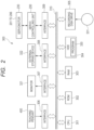
- FIG. 2 is a block diagram for illustrating the robot controlling device of the robot apparatus according to the first embodiment.
- the robot controlling device 300 which is constituted by a computer, comprises a CPU (central processing unit) 301 which serves as a controlling unit (processing unit).
- the robot controlling device 300 comprises an ROM (read only memory) 302, an RAM (random access memory) 303 and an HDD (hard disk drive) 304 which serve as storing units.
- the robot controlling device 300 comprises a recording disk drive 305, and various interfaces 306 to 309.
- the ROM 302, the RAM 303, the HDD 304, the recording disk drive 305 and the various interfaces 306 to 309 are respectively connected to the CPU 301 via a bus 310.
- basic programs such as a BIOS (basic input/output system) and the like have been stored in the ROM 302.
- the RAM 303 is a storing device which temporarily stores therein various data such as arithmetic operation results of the CPU 301, and the like.
- the HDD 304 is a storing device which stores therein the arithmetic operation results of the CPU 301, various data obtained externally, and the like.
- the HDD also stores therein a program 330 to be used to cause the CPU 301 to perform later-described arithmetic operation processes.
- the CPU 301 performs respective processes in a robot controlling method, on the basis of the program 330 recorded (stored) in the HDD 304.
- the recording disk drive 305 can read out various data, programs and the like recorded on a recording disk 331.
- the teaching pendant 400 is connected to the interface 306.
- the CPU 301 receives teaching data input from the teaching pendant 400 via the interface 306 and the bus 310.
- the servo controlling unit 230 is connected to the interface 309.
- the CPU 301 obtains detection results from the respective sensor units 221 to 226 via the servo controlling unit 230, the interface 309 and the bus 310. Besides, the CPU 301 outputs the data indicating the torque instruction value of each of the joints to the servo controlling unit 230 via the bus 310 and the interface 309, at a predetermined time interval.
- a monitor 321 is connected to the interface 307.
- the monitor 321 is used to display various images under the control of the CPU 301.
- An external storing device 322, which serves as a storing unit such as a rewritable nonvolatile memory, an external HDD or the like, can be connected to the interface 308.
- the HDD 304 serves as a computer-readable recording medium
- the program 330 is stored in the HDD 304.
- the present invention is not limited to such a constitution.
- the program 330 may be recorded on any kind of recording medium if it can be read by a computer.
- the recording medium for supplying the program 330 it may be possible to use the ROM 302, the recording disk 331, the external storing device 322 or the like as illustrated in FIG. 2 . More specifically, as the recording medium, it is possible to use a flexible disk, a hard disk, an optical disk, a magneto optical disk, a CD-ROM, a CD-R, a magnetic tape, a nonvolatile memory, an ROM or the like.
- FIG. 3 is a control block diagram for illustrating the control system of the robot apparatus according to the first embodiment.
- the CPU 301 of the robot apparatus 300 functions as a force detecting unit 504, a force controlling unit 505 and a position target value generating unit 506, by executing the program 330.
- the servo controlling unit 230 functions as a plurality of switch controlling units 511 to 516 (i.e., six switch controlling units corresponding to the six joints), a plurality of position controlling units 521 to 526 (i.e., six position controlling units corresponding to the six joints), and a plurality of motor controlling units 531 to 536 (i.e., six motor controlling units corresponding to the six joints).
- the sensor units 221 to 226 comprise angle sensors (position sensors) 551 to 556 and torque sensors 541 to 546, respectively.
- the angle sensors 551 to 556 detect the angles (positions) of the electric motors 211 to 216 or the joints J 1 to J 6 , respectively.
- the angle sensors 551 to 556 directly detect angles ⁇ 1 to ⁇ 6 of the respective electric motors 211 to 216, respectively.
- angles q 1 to q 6 of the respective joints J 1 to J 6 can be obtained from the angles ⁇ 1 to ⁇ 6 respectively on the basis of a speed reduction ratio of a not-illustrated speed reducer.
- the angles sensors 551 to 556 indirectly detect the angles q 1 to q 6 of the respective joints J 1 to J 6 , respectively.
- the torque sensors 541 to 546 detect torques ⁇ 1 to ⁇ 6 of the respective joints J 1 to J 6 , respectively.
- a position detecting unit 550 for detecting a position P of the hand tip of the robot 200 is constituted by the plurality of angle sensors 551 to 556, and a force detecting unit (torque sensor) 540 for detecting force (hand tip force) F acting on the hand tip of the robot 200 is constituted by the plurality of torque sensors 541 to 546.
- the teaching pendant 400 outputs a force target value F ref included in force teaching data 501 and a position target value P ref included in position teaching data 502 to the CPU 301, in response to an operation by an operator.
- the force target value F ref which is the target value of the hand tip force of the robot 200
- the position target value P ref which is the target value of the hand tip position of the robot 200
- a robot model 503 has been stored in the external storing device 322.
- the teaching pendant 400 When the stop button 401 is depressed by the operator, the teaching pendant 400 outputs the stop order to the force controlling unit 505 of the CPU 301.
- the force detecting unit 504 calculates a current position P(t) of the hand tip of the robot 200 and the hand tip force F of the robot 200 at that time, by using the torques ⁇ 1 to ⁇ 6 respectively detected by the torque sensors 541 to 546 and the angles q 1 to q 6 respectively detected by the angle sensors 551 to 556.
- the force controlling unit 505 inputs the robot model 503 (virtual mass M ref ), the force target value F ref , the position target value P ref , a stiffness coefficient K ref , a viscosity coefficient D ref , the current position P(t) and the force F. Then, the force controlling unit 505 obtains torque instruction values ⁇ MFref1 to ⁇ MFref6 for the respective joints J 1 to J 6 , using the input values.
- the force controlling unit obtains the torque instruction values ⁇ MFref1 to ⁇ MFref6 such that a force deviation between the hand tip force F and the force target value F ref , a position deviation between the position P(t) of the hand tip and the position target value P ref , and a speed deviation between a speed P(t) ( ⁇ ) of the hand tip and a speed target value P ref ( ⁇ ) become small respectively.
- the force controlling unit 505 outputs the obtained torque instruction values ⁇ MFref1 to ⁇ MFref6 to the switch controlling units 511 to 516, respectively.
- the force controlling unit 505 obtains the speed P(t)( ⁇ ) of the hand tip from the position P(t) of the hand tip being the detection result of the position detecting unit 550.
- the position detecting unit 550 it may be possible for the position detecting unit 550 to output the data itself of the speed P(t) ( ⁇ ) of the hand tip by the arithmetic operation.
- the position detecting unit 550 also serves as a speed detecting unit for detecting the speed of the hand tip.
- the symbol ( ⁇ ) indicates one (single) differentiation to be performed with respect to time.
- the position target value generating unit 506 obtains angle instruction values (position instruction values) q ref1 to q ref6 of the respective joints J 1 to J 6 from the position target value P ref of the hand tip by inverse kinematics calculation, and outputs the obtained angle instruction values q ref1 to q ref6 to the position controlling units 521 to 526, respectively.
- the position controlling units 521 to 526 respectively obtain torque instruction values ⁇ MPref1 to ⁇ MPref6 such that angle deviations between the angles q 1 to q 6 of the respective joints J 1 to J 6 and the angle instruction values q ref1 to q ref6 of the respective joints J 1 to J 6 become small, respectively.
- to reduce the angle deviations is equivalent to reduce the angle deviations between the angles of the respective electric motors 211 to 216 and the angle instruction values obtained by converting the angle instruction values q ref1 to q ref6 with the speed reduction ratio or the like of the speed reducer.
- the position controlling units 521 to 526 output the torque instruction values ⁇ MPref1 to ⁇ MPref6 to the switch controlling units 511 to 516, respectively.
- the switch controlling units 511 to 516 perform switch control between a force control mode of performing the torque-based force control and a position control mode of performing the position-based force control.
- the switch controlling units 511 to 516 output the torque instruction values ⁇ MFref1 to ⁇ MFref6 as torque instruction values ⁇ Mref1 to ⁇ Mref6 to the motor controlling units 531 to 536, respectively.
- the switch controlling units 511 to 516 output the torque instruction values ⁇ MPref1 to ⁇ MPref6 as the torque instruction values ⁇ Mref1 to ⁇ Mref6 to the motor controlling units 531 to 536, respectively.
- the motor controlling units 531 to 536 energize the electric motors 211 to 216 by respective currents Cur 1 to Cur 6 to achieve the torque instruction values ⁇ Mref1 to ⁇ Mref6 , based on the angles (positions) ⁇ 1 to ⁇ 6 of the respective electric motors 211 to 216.
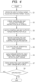
- FIG. 4 is a flow chart for describing the force control to be performed to the robot 200 in the first embodiment.
- the operator inputs the force target value F ref and the position target value P ref to the teaching pendant 400 (S1).
- the force target value F ref is stored to the force teaching data 501
- the position target value P ref is stored to the position teaching data 502.
- the position target value P ref corresponds to the position at which the force control operation is started.
- the force controlling unit 505 calculates the torque instruction values (force) ⁇ Mref1 to ⁇ Mref6 to the respective motors 211 to 216 by using the robot model 503 such that the hand tip force F follows the force target value F ref , that is, the deviation between the hand tip force F and the force target value F ref becomes small (S2).
- the switch controlling units 511 to 516 output the torque instruction values (force) ⁇ ref1 to ⁇ MFref6 as the torque instruction values ⁇ Mref1 to ⁇ Mref6 to the motor controlling units 531 to 536, respectively (S3).
- the motor controlling units 531 to 536 perform energization control to achieve the respective torque instruction values ⁇ Mref1 to ⁇ Mref6 , based on the angles ⁇ 1 to ⁇ 6 of the respective electric motors 211 to 216 (S4).
- the electric motors 211 to 216 respectively generate the joint torques ⁇ 1 to ⁇ 6 based on energization (S5) .
- the angle sensors 551 to 556 detect the angles q 1 to q 6 of the respective joints J 1 to J 6 (i.e., the angles ⁇ 1 to ⁇ 6 of the respective electric motors 211 to 216).
- the torque sensors 541 to 546 respectively detect the torques ⁇ 1 to ⁇ 6 of the respective joints J 1 to J 6 (S6).
- the angles q 1 to q 6 of the respective joints J 1 to J 6 and the torques ⁇ 1 to ⁇ 6 of the respective joints J 1 to J 6 are respectively fed back to the CPU 301 of the robot controlling device 300.
- the force detecting unit 504 (i.e., the CPU 301) converts the torques ⁇ 1 to ⁇ 6 of the respective joints J 1 to J 6 into the hand tip force F acting on the hand tip of the robot 200 at the current position P(t), based on the robot model 503 and the angles q 1 to q 6 of the respective joints J 1 to J 6 (S7).
- the angles ⁇ 1 to ⁇ 6 of the respective electric motors 211 to 216 instead of the angles q 1 to q 6 of the respective joints J 1 to J 6 .
- the CPU 301 decides whether or not the driving ends (S8). When the driving does not end (S8: NO), the CPU repeatedly performs the processes in S2 to S7.
- the order of the processes is not limited to that described in the flow chart of FIG. 4 . Namely, it is possible to achieve the force control in another order.
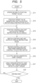
- FIG. 5 is a flow chart for describing the position control to be performed to the robot 200 in the first embodiment.
- the operator inputs the position target value P ref to the teaching pendant 400 (S11).
- the position target value P ref is stored in the position teaching data 502.
- the position target value generating unit 506 converts the position target value P ref into the angle instruction values q ref1 to q ref6 of the respective joints J 1 to J 6 , based on the robot model 503 (S12).
- the position controlling units 521 to 526 calculate the torque instruction values (angles) ⁇ MPref1 to ⁇ MPref6 of the respective electric motors 211 to 216 such that the angles q 1 to q 6 of the respective joints J 1 to J 6 follow the angle instruction values q ref1 to q ref6 of the respective joints J 1 to J 6 (S13).
- signals indicating the angles of the respective joints J 1 to J 6 it is may be possible to use the angles ⁇ 1 to ⁇ 6 of the respective electric motors 211 to 216, instead of the angles q 1 to q 6 .
- the switch controlling units 511 to 516 output the torque instruction values (angles) ⁇ MPref1 to ⁇ MPref6 as the torque instruction values ⁇ Mref1 to ⁇ Mref6 to the motor controlling units 531 to 536, respectively (S14).
- the force control by the processes in S1 to S8 and the position control by the processes in S11 to S18 are switched by the switch controlling units 511 to 516.
- either one of the force control and the position control is selected according to the content of the operation or work.
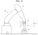
- FIG. 6 is a schematic diagram for illustrating the state that an assembling operation is performed by the robot according to the first embodiment.
- the robot hand 252 is moved downward by the torque-based force control, to perform the assembling operation (fitting operation) of assembling (fitting) a cylindrical workpiece W1 being a first part supported (grasped) by the robot hand 252 to a circular workpiece W2 being a second part.
- FIG. 7 is a block diagram for illustrating the detail of the force controlling unit 505 illustrated in FIG. 3 .
- FIG. 8 is a flow chart for describing a manufacturing method of an assembly according to the first embodiment.
- the force controlling unit 505 comprises a stop order confirming unit 601, a speed reduction parameter setting unit 602 and a force control calculating unit 603.
- the force controlling unit 505 starts the assembling operation (S21).
- the stop order confirming unit 601 decides whether or not a stop order for stopping the robot 200 is received, that is, whether or not the stop button 401 is depressed (S22: deciding process, deciding step). For example, when the CPU 301 decides that it is necessary to stop a device due to some kind or another abnormality occurs in the device, the stop order is issued via the teaching pendant 400 of FIG. 1 . Besides, it may be possible to previously write the stop order in the robot program for defining the operation of the robot 200, so that the robot 200 may be stopped based on the robot program.
- the force control calculating unit 603 performs calculations by the equations (1) and (2), based on following variations.
- the expression (1) is merely an example of the force control. Namely, the force control according to the present invention is not limited to this expression.
- the force control calculating unit 603 calculates the torque instruction values ⁇ MFref1 to ⁇ MFref6 to be output to the respective switch controlling units 511 to 516 of FIG. 3 , from the expression (1). Then, the force control calculating unit 603 decides whether or not the assembling operation is completed (S23). When the assembling operation is completed (S23: YES), the process ends immediately. On the other hand, when the assembling operation is not yet completed (S23: NO), the process returns to S22.
- FIGS. 9A to 9C are graphs respectively indicating the force target values to time. More specifically, FIG. 9A is the graph indicating the force target value F ref linearly decreased to time from the time t triger at which the stop order was received, FIG. 9B is the graph indicating the force target value F ref decreased stepwise to time from the time t triger at which the stop order was received, and FIG. 9C is the graph indicating the force target value F ref nonlinearly decreased to time from the time t triger at which the stop order was received.
- the force target value F ref is the vector which consists of translation XYZ and rotation XYZ, only one direction is illustrated in FIGS. 9A to 9C for the purpose of simplification.
- the force target value F ref shown in each of FIGS. 9A to 9C is monotonously decreased to time. More specifically, the force target value F ref shown in FIG. 9A is linearly decreased.
- the force target value F ref shown in FIG. 9B is instantaneously switched to "0" at the time t triger of the stop order, and this value is used when the operator wishes to reduce speed earlier than the case where the force target value F ref shown in FIG. 9A is used. For example, this value can be used when the speed at the time of the stop order is slow (low), or when the operator wishes to stop the robot as soon as possible in the state that the workpiece W1 is not in contact with the workpiece W2.
- this value can be used when making the movements at the time of speed reduction start and at the time of stop completion smooth as compared with the case shown in FIG. 9A .
- this value can be used when the operator wishes to stop the robot without adding a load on the workpiece W1.
- the shown methods of decreasing the force target value are merely examples, and the present invention is not limited to these methods.
- the present invention is not limited to this.
- the CPU 301 can stop the robot 200 while reducing the load added to the robot 200 and the workpieces W1 and W2.
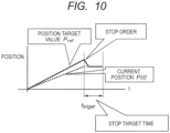
- FIG. 10 is a graph indicating the position of the hand tip to time and the position target value.
- the position target value P ref is the vector which consists of translation XYZ and rotation XYZ, only one direction is illustrated in FIG. 10 for the purpose of simplification.
- the position deviation between the position target value P ref and the actual position P exists at the instant when the stop order is received.
- the position deviation becomes small extremely by setting the position target value P ref to the fixed value P(t triger ) immediately after the stop order was received.
- the force control calculating unit 603 calculates the torque instruction values ⁇ MFref1 to ⁇ MFref6 by using such a changed parameter.
- the robot 200 by decreasing the force target value F ref and further setting the position target value P ref to the fixed value, it is possible to stop the robot 200 in the state that the position of the hand tip of the robot 200 is fixed, while reducing the load added to the robot 200 and the workpiece.
- the CPU 301 decides whether or not the robot 200 is stopped in S24 (S25: stop deciding process, stop deciding step).
- S24 stop deciding process, stop deciding step.
- the CPU 301 When it is decided in S25 that the robot 200 is stopped (S25: YES), the CPU 301 operates the respective brakes 231 to 236 to fix the respective joints J 1 to J 6 of the robot 200 (S26: fixing process, fixing step). In this case, the motor controlling units 531 to 536 stop power supply to the motors 211 to 216, respectively. Thus, even if external force acts on the robot 200 and the workpiece W1 after the robot 200 was stopped, the robot 200 does not move.
- FIG. 11A is a graph indicating displacement of the robot hand 252 in the X direction (i.e., the horizontal direction in regard to the base of the robot hand) in case of performing the stopping process while maintaining the torque-based force control.
- the graph illustrated in FIG. 11A corresponds to the experimental result obtained in the first embodiment.
- the position deviation of the hand tip is small.
- the position target value P ref is fixed to the value of the current position (see FIG. 10 ) at the time when the stop order was received, it is possible to effectively restrain the hand tip from shifting or fluctuating from the time of the reception of the stop order.
- FIG. 11B is a graph indicating displacement of the robot hand 252 in the X direction in case of performing the stopping process by switching the torque-based force control to the position control.
- the graph illustrated in FIG. 11B corresponds to the experimental result obtained in a comparative example.
- a position deviation (aberration) of the robot hand 252 caused due to the individual difference of the robot 200 is large and the speed of the hand tip of the robot 200 is high.
- the position target value P ref is fixed to the value (see FIG. 10 ) at the time when the stop order was received, the hand tip overshoots the position at which the stop order was received.
- the position deviation becomes large after the stop order.
- the robot 200 stops after the workpiece W2 which is being in contact with the robot, because the force target value is decreased and the position target value is fixed to the current position at the time of the reception of the stop order. For this reason, it is possible to stably stop the robot 200 while maintaining the force control.
- the position deviation of the hand tip of the robot 200 is small and the workpiece is made by a soft material, it is possible to prevent destruction of the workpiece.
- the workpiece is made by a hard material, it is possible to prevent destruction of the robot 200 caused due to an overload added to the robot 200.
- since the workpieces to be handled are not mutually caught (or seized) each other, it is possible to easily return or restore the operation of the robot after the robot was once stopped.
- the robot apparatus in the stopping process of stopping the robot, the position target value P ref is fixed.
- the speed target value P ref ( ⁇ ) is decreased.
- the constitution of the robot apparatus in the second embodiment is the same as that in the first embodiment.
- the robot controlling method (assembly manufacturing method) according to the second embodiment a part of the process to be performed by the CPU 310 (concretely, the process to be performed by the speed reduction parameter setting unit 602 illustrated in FIG. 7 ) is different from the process described in the first embodiment. Therefore, only the process to be performed by the speed reduction parameter setting unit 602 will be described hereinafter.
- the operation descry bed in the second embodiment is effective in a case where an actual hand tip speed at the time when the stop order is received by the CPU 301 is high.
- the method of decreasing the force target value F ref is the same as that in the first embodiment.
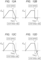
- FIGS. 12A to 12D are graphs respectively indicating the speed target value P ref ( ⁇ ) to time. More specifically, FIG. 12A is the graph indicating the speed target value P ref ( ⁇ ) linearly decreased to time from the time t triger at which the stop order was received, FIG. 12B is the graph indicating the speed target value P ref ( ⁇ ) decreased stepwise to time from the time t triger at which the stop order was received, FIG. 12C is the graph indicating the speed target value P ref ( ⁇ ) nonlinearly decreased to time from the time t triger at which the stop order was received, and FIG.
- FIGS. 12A to 12D is the graph indicating the speed target value P ref ( ⁇ ) decreased to time while overshooting from the time t trigerf at which he stop order was received.
- the speed target value P ref ( ⁇ ) is the vector which consists of translation XYZ and rotation XYZ, only one direction is illustrated in FIGS. 12A to 12D for the purpose of simplification.
- the speed target value P ref ( ⁇ ) shown in each of FIGS. 12A to 12C is monotonously decreased to time. More specifically, the speed target value P ref ( ⁇ ) shown in FIG. 12A is linearly decreased.
- the speed target value P ref ( ⁇ ) shown in FIG. 12B is instantaneously switched to "0" at the time t triger of the stop order, and this value is used when the operator wishes to reduce speed earlier than the case where the speed target value shown in FIG. 12A is used. For example, this value can be used when the speed at the time of the stop order is slow (low), or when the operator wishes to stop the robot as soon as possible in the state that the workpiece W1 is not in contact with the workpiece W2.
- the speed target value P ref ( ⁇ ) shown in FIG. 12C is nonlinearly decreased, and this value can be used when it intends to make the movements at the time of speed reduction start and at the time of speed reduction completion smooth as compared with the case shown in FIG. 12A .
- this value can be used when the operator wishes to stop the robot without adding a load any more.
- the speed target value P ref ( ⁇ ) shown in FIG. 12D is obtained by once waving the value to the side opposite to "0" and then converging the waved value to "0" while taking into account the overshoot of the position. By using this value, it is possible to reduce the speed and stop the robot more quickly.
- the shown methods of decreasing the speed target value are merely examples, and the present invention is not limited to these methods.
- the present invention is not limited to this.
- the CPU 301 in the case where the CPU 301 receives the stop order for stopping the robot in the middle of the force control, the CPU stops the robot 200 while maintaining the force control, by decreasing the force target value and further decreasing the speed target value. For this reason, it is possible to stop the robot 200 such that the workpiece W1 being in contact with the workpiece W2 follows the workpiece W2. Thus, it is possible to stop the robot 200 without adding an excessive load to the robot 200 and the workpieces W1 and W2.
- the workpieces to be handled are not mutually caught (or seized) each other, it is possible to easily return or restore the operation of the robot after the robot was once stopped.
- the position target value P ref is fixed in the stopping process of stopping the robot.
- the speed target value P ref ( ⁇ ) is decreased in the stopping process of stopping the robot.
- the speed reduction parameter setting unit 602 fixes (holds) the position target value P ref to the fixed value P(t triger ) while decreasing the force target value F ref after the time t triger at which the stop order was received, thereby decreasing the speed target value P ref ( ⁇ ).
- the method of fixing the position target value and the method of decreasing the force target value are the same as those described in the first embodiment, and the method of decreasing the speed target value is the same as that described in the second embodiment.
- the speed reduction parameter setting unit 602 decreases the stiffness coefficient K ref of the robot 200.
- the workpiece W1 flexibly follows the workpiece W2 as compared with the case described in the first embodiment. For this reason, it is possible to stably stop the robot 200.
- FIGS. 13A and 13B are graphs respectively indicating the stiffness coefficient K ref to time. More specifically, FIG. 13A is the graph indicating the stiffness coefficient K ref linearly decreased to time from the time t triger at which the stop order was received, and FIG. 13B is the graph indicating the stiffness coefficient K ref nonlinearly decreased to time from the time t triger at which the stop order was received.
- the stiffness coefficient K ref is composed by the matrix, only one component of the relevant matrix is shown for the purpose of a simplified description.
- the stiffness coefficient K ref shown in each of FIGS. 13A and 13B is monotonously decreased to time. More specifically, the stiffness coefficient K ref shown in FIG. 13A is linearly decreased to time. On the other hand, the stiffness coefficient K ref shown in FIG. 13B is nonlinearly decreased to time, and this coefficient is used in a case where it intends to make the movement of the robot at the speed reduction start time and the speed reduction completion time smooth as compared with the case where the stiffness coefficient K ref is linearly decreased to time. For example, this coefficient is used in a case where it intends to stop the robot 200 with a lesser load to be added.
- the shown methods of decreasing the stiffness coefficient are merely examples. Namely, the present invention is not limited only to these methods. In any case, it may be possible to decrease the whole of the matrix of the stiffness coefficient. Alternatively, it may be possible to decrease only the component of the matrix of the stiffness coefficient related to a desired direction according to an operation of the robot.
- the CPU stops the robot 200 while maintaining the force control by changing the force target value, the position target value and the stiffness coefficient. For this reason, it is possible to stop the robot 200 so as to follow the workpiece W2 which is being in contact with the workpiece W1. Moreover, as compared with the case where the stiffness coefficient is not decreased, it is possible for the robot to flexibly follow the workpiece. For this reason, it is possible to stop the robot with a lesser load to be added on the robot and the workpiece. In addition, according to the present embodiment, since the workpieces to be handled are not mutually caught (or seized) each other, it is possible to easily return or restore the operation of the robot after the robot was once stopped.
- the speed reduction parameter setting unit 602 decreases the viscosity coefficient D ref of the robot 200.
- the robot flexibly follows the workpiece as compared with the case described in the second embodiment. For this reason, it is possible to stably stop the robot 200.
- FIGS. 14A and 14B are graphs respectively indicating the viscosity coefficient D ref to time. More specifically, FIG. 14A is the graph indicating the viscosity coefficient D ref linearly decreased to time from the time t triger at which the stop order was received, and FIG. 14B is the graph indicating the viscosity coefficient D ref nonlinearly decreased to time from the time t triger at which the stop order was received.
- the viscosity coefficient D ref is composed by the matrix, only one component of the relevant matrix is shown for the purpose of a simplified description.
- the viscosity coefficient D ref shown in each of FIGS. 14A and 14B is monotonously decreased to time. More specifically, the viscosity coefficient D ref shown in FIG. 14A is linearly decreased to time. On the other hand, the viscosity coefficient D ref shown in FIG. 14B is nonlinearly decreased to time, and this coefficient is used in a case where it intends to make the movement of the robot at the speed reduction start time and the start reduction completion time smooth as compared with the case where the viscosity coefficient D ref is linearly decreased to time. For example, this coefficient is used in a case where it intends to stop the robot 200 with a lesser load to be added.
- the shown methods of decreasing the viscosity coefficient are merely examples. Namely, the present invention is not limited only to these methods. In any case, it may be possible to decrease the whole of the matrix of the viscosity coefficient. Alternatively, it may be possible to decrease only the component of the matrix of the viscosity coefficient related to a desired direction according to an operation of the robot.
- the CPU stops the robot 200 while maintaining the force control by changing the force target value, the speed target value and the viscosity coefficient. For this reason, it is possible to stop the robot 200 so as to follow the workpiece W2 which is being in contact with the workpiece W1. Moreover, as compared with the case where the viscosity coefficient is not decreased, it is possible for the robot to flexibly follow the workpiece. For this reason, it is possible to stop the robot with a load less to be added on the robot and the workpiece. In addition, according to the present embodiment, since the workpieces are not mutually caught (or seized) each other, it is possible to easily return or restore the operation of the robot after the robot was once stopped.
- the modified example 2 is different from the modified example 1 on the point that the speed reduction parameter setting unit 602 of FIG. 7 decreases the force target value, fixes the position target value and decreases the speed target value, and further decreases the stiffness coefficient and the viscosity coefficient which are given from the force teaching data 501 illustrated in FIG. 3 .
- the method of decreasing the stiffness coefficient is the same as that described in the third embodiment, and the method of decreasing the viscosity coefficient is the same as that described in the fourth embodiment.
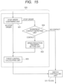
- a workpiece contact detecting unit 604 is provided between the stop order confirming unit 601 and the speed reduction parameter setting unit 602 of FIG. 7 described in the first embodiment, as illustrated in FIG. 15 .
- the workpiece contact detecting unit 604 obtains the force which acts on the hand tip.
- the sensor for obtaining the force acting on the hand tip is equivalent to the plurality of torque sensors for respectively detecting and obtaining the torques of the respective joints. That is, the force detecting unit 504 calculates the current position P(t) of the hand tip of the robot 200 and the hand tip force F of the robot 200 at that time, by using the torques ⁇ 1 to ⁇ 6 respectively detected by the torque sensors 541 to 546 and the angles q 1 to q 6 respectively detected by the angle sensors 551 to 556. Otherwise, it may be possible to calculate the hand tip force F of the robot 200 by using a force sensor provided or attached to the hand tip.
- the calculated hand tip force F is compared with a predetermined threshold previously stored in a storing unit.
- the process is advanced to the speed reduction parameter setting unit.
- the control is switched from the force control to the position control by the switch controlling units 511 to 516, and then the robot stops. That is, the instruction value for each motor is obtained such that the respective values of the plurality of sensors respectively detecting the positions of the motors or the joints become predetermined values respectively.
- FIG. 16 is a graph indicating a change of the hand tip force F to time in the case where the robot is in contact with the workpiece.
- the hand tip force is the vector which consists of translation XYZ and rotation XYZ, only one direction is illustrated for the purpose of simplification.
- the contact detection using the threshold as shown in FIG. 16 is merely an example, and the present invention is not limited to this.
- the robot when the stop order is received by the CPU 301 in the middle of the force control and it is decided that the robot is not in contact with the workpiece, the robot is stopped by switching the control from the force control to the position control. For this reason, it is possible to stop the robot quickly as compared with the case where the robot is stopped in the force control.
- the present invention is not limited to the above embodiments. That is, various kinds of modifications can be achieved within the range of the technical idea of the present invention. Besides, it should be noted that the effects described in the above embodiments are merely the recitations of the most preferable effects derived from the present invention. That is, the effects derived from the present invention are not limited to them.
- the present invention can be achieved also by a process in which a program for achieving one or more functions of the above embodiments is supplied to a system or an apparatus via a network or a storage medium and then one or more processors provided in the computer of the relevant system or the relevant apparatus read out and execute the supplied program.
- a circuit for example, an ASIC (application specific integrated circuit) which achieves one or more functions of the above embodiments.
- the robot 200 (the robot arm 251) is the vertical multi-joint robot.
- the present invention is not limited to this. That is, as the robot, it may be possible to use various kinds of robots such as a horizontal multi-joint robot, a parallel link robot, an orthogonal robot, and the like.
- the driving direction of the joint is not limited to the rotation direction. Namely, the driving direction of the joint includes a linear-motion direction (expansion-and-contraction (stretching) direction).
- the joint is driven by the electric motor.
- the present invention is not limited to this. Namely, it may be possible to drive the joint by, for example, an artificial muscle or the like.
- the robot has the six joints. However, in the present invention, the number of the joints to be used is not limited to this.
- the force detecting unit is constituted by the plurality of torque sensors.
- the present invention is not limited to this. Namely, it may be possible to constitute the force detecting unit by a force sensor which is provided at the tip of the robot arm.
- Embodiment(s) of the present invention can also be realized by a computer of a system or apparatus that reads out and executes computer executable instructions (e.g., one or more programs) recorded on a storage medium (which may also be referred to more fully as a 'non-transitory computer-readable storage medium') to perform the functions of one or more of the above-described embodiment(s) and/or that includes one or more circuits (e.g., application specific integrated circuit (ASIC)) for performing the functions of one or more of the above-described embodiment(s), and by a method performed by the computer of the system or apparatus by, for example, reading out and executing the computer executable instructions from the storage medium to perform the functions of one or more of the above-described embodiment(s) and/or controlling the one or more circuits to perform the functions of one or more of the above-described embodiment(s).
- computer executable instructions e.g., one or more programs
- a storage medium which may also be referred to more fully as
- the computer may comprise one or more processors (e.g., central processing unit (CPU), micro processing unit (MPU)) and may include a network of separate computers or separate processors to read out and execute the computer executable instructions.
- the computer executable instructions may be provided to the computer, for example, from a network or the storage medium.
- the storage medium may include, for example, one or more of a hard disk, a random-access memory (RAM), a read only memory (ROM), a storage of distributed computing systems, an optical disk (such as a compact disc (CD), digital versatile disc (DVD), or Blu-ray Disc (BD) TM ), a flash memory device, a memory card, and the like.
- a robot apparatus which is characterized by comprising: a robot comprising a plurality of motors for driving respective joints and a sensor for obtaining force acting on a hand tip; and a controlling unit for obtaining a torque instruction value for each of the plurality of motors such that a force deviation between the force acting on the hand tip and a force target value becomes small, controlling driving of each of the plurality of motors based on the torque instruction value, and performing a stopping process of decreasing the force target value when a stop order for stopping the robot is received.
Landscapes
- Engineering & Computer Science (AREA)
- Robotics (AREA)
- Mechanical Engineering (AREA)
- Human Computer Interaction (AREA)
- Manipulator (AREA)
Claims (12)
- Robotervorrichtung, mit:einem Roboter (200), der eine Vielzahl von Motoren (211 bis 216), die konfiguriert sind, um jeweilige Gelenke (J1 bis J6) anzutreiben, einen Sensor (540), der konfiguriert ist, um eine auf eine Handspitze wirkende Kraft zu erhalten, und einen Sensor (550), der konfiguriert ist, um eine Position der Handspitze zu erhalten, aufweist, wobei der Sensor (540), der konfiguriert ist, um die auf die Handspitze wirkende Kraft zu erhalten, einen Drehmomentsensor aufweist, der konfiguriert ist, um ein Drehmoment von jedem der Gelenke (J1 bis J6) zu erhalten, und der Sensor (550), der konfiguriert ist, um die Position der Handspitze zu erhalten, eine Vielzahl von Sensoren (551 bis 556; 221 bis 226) umfasst, die konfiguriert sind, um jeweilige Positionen der Motoren (211 bis 216) oder jeweilige Positionen der Gelenke (J1 bis J6) zu erfassen; undeiner Steuerungseinheit (300), die konfiguriert ist, umeinen Drehmomentanweisungswert für jeden der Motoren (211 bis 216) zu erhalten, um eine Kraftabweichung zwischen der auf die Handspitze wirkenden Kraft und einem Kraftsollwert zu kompensieren, undeinen Antriebs von jedem der Motoren (211 bis 216) auf der Grundlage des Drehmomentanweisungswertes zu steuern,dadurch gekennzeichnet, dassdie Robotervorrichtung weiterhin eine Kraftsteuerungseinheit (505) aufweist, die eine Geschwindigkeitsreduktionsparametereinstelleinheit (602), eine Kraftsteuerungsberechnungseinheit (603) und eine Stoppanweisungsbestätigungseinheit (601) aufweist, die konfiguriert ist, um zu entscheiden, ob eine Stoppanweisung zum Stoppen des Roboters (200) im Montagebetrieb empfangen wird oder nicht, unddie Steuerungseinheit (300) in einem Fall, in dem die Stoppanweisungsbestätigungseinheit (601) entscheidet, dass die Stoppanweisung empfangen wird, konfiguriert ist, um einen Stoppvorgang durchzuführen,wobei in dem Stoppvorgang die Steuerungseinheit (300) konfiguriert ist, um unter Verwendung der Geschwindigkeitsreduktionsparametereinstelleinheit (602), als einen festen Wert eines Positionssollwertes, eine Position der Handspitze einzustellen, wenn die Stoppanweisungsbestätigungseinheit (601) entscheidet, dass die Stoppanweisung empfangen wird, konfiguriert ist, um den Drehmomentanweisungswert zu erhalten, um eine Positionsabweichung zwischen der Position der Handspitze und dem Positionssollwert unter Verwendung der Kraftsteuerungsberechnungseinheit (603) zu kompensieren, und konfiguriert ist, um den Kraftsollwert unter Verwendung der Kraftsteuerungsberechnungseinheit (603) zu kompensieren, um die auf die Handspitze wirkende Kraft zu verringern.
- Robotervorrichtung gemäß Anspruch 1, wobei in einem Fall, dass der Positionssollwert im Stoppvorgang auf den festen Wert gesetzt wird, die Steuerungseinheit (300) konfiguriert ist, um einen Steifigkeitskoeffizienten des Roboters (200) zu verringern.
- Robotervorrichtung gemäß Anspruch 1, wobeidie Steuerungseinheit konfiguriert ist, um eine Geschwindigkeit der Handspitze aus einem Wert des Sensors (550), der konfiguriert ist, um die Position der Handspitze zu erhalten, zu erhalten, undin einem Fall, dass der Drehmomentanweisungswert erhalten wird, um eine Geschwindigkeitsabweichung zwischen der Geschwindigkeit der Handspitze und einem Geschwindigkeitssollwert im Stoppvorgang zu kompensieren, die Steuerungseinheit (300) konfiguriert ist, den Geschwindigkeitssollwert zu verringern.
- Robotervorrichtung gemäß Anspruch 3, wobei in einem Fall, dass der Geschwindigkeitssollwert im Stoppvorgang verringert wird, die Steuerungseinheit (300) konfiguriert ist, um einen Viskositätskoeffizienten des Roboters (200) zu verringern.
- Robotervorrichtung gemäß Anspruch 1, wobeider Roboter (200) eine Bremse (231 bis 236) aufweist, die konfiguriert ist, um jedes der Gelenke (J1 bis J6) zu bremsen, unddie Steuerungseinheit (300) konfiguriert ist, um jedes der Gelenke (J1 bis J6) des Roboters (200) durch die Bremse (231 bis 236) zu fixieren, nachdem der Roboter (200) im Stoppvorgang gestoppt wurde.
- Robotervorrichtung gemäß einem der Ansprüche 1 bis 5, weiterhin mit einem Programmiergerät (400) umfassend eine Stopptaste, die konfiguriert ist, um als Stoppbedienungseinheit zu dienen, die konfiguriert ist, um die Stoppanweisung an die Steuerungseinheit (300) als Reaktion auf die Bedienung durch einen Bediener zu übertragen.
- Robotervorrichtung gemäß einem der Ansprüche 1 bis 6, wobei in dem Fall, in dem die Stoppanweisungsbestätigungseinheit (601) entscheidet, dass die Stoppanweisung empfangen wird, die Steuerungseinheit (300) konfiguriert ist, um den Stoppvorgang durchzuführen, wenn die auf die Handspitze wirkende Kraft einen vorbestimmten Schwellenwert überschreitet, und konfiguriert ist, um den Roboter (200) unter Verwendung der Positionssteuerung zu stoppen, wenn die auf die Handspitze wirkende Kraft kleiner als der vorbestimmte Schwellenwert ist.
- Robotervorrichtung gemäß einem der Ansprüche 1 bis 7, wobei der Kraftsollwert innerhalb einer vorbestimmten Stoppsollzeit auf einen Wert nahe 0 verringert wird, in einem Fall, dass der Kraftsollwert unter Verwendung der Kraftsteuerungsberechnungseinheit (603) kompensiert wird, um die auf die Handspitze wirkende Kraft zu verringern.
- Robotervorrichtung gemäß Anspruch 8, wobei der Kraftsollwert linear, nichtlinear oder augenblicklich auf den Wert nahe 0 verringert wird, in einem Fall, dass der Kraftsollwert innerhalb der vorbestimmten Stoppsollzeit auf den Wert nahe 0 verringert wird.
- Steuerungsverfahren eines Roboters, der eine Vielzahl von Gelenken, eine Vielzahl von Motoren, die zum Antreiben der jeweiligen Gelenke konfiguriert sind, einen Sensor, der konfiguriert ist, um eine auf eine Handspitze wirkende Kraft zu erfassen, und einen Sensor, der konfiguriert ist, um eine Position der Handspitze zu erfassen, aufweist, wobei der Sensor, der konfiguriert ist, um die auf die Handspitze wirkende Kraft zu erfassen, einen Drehmomentsensor umfasst, der konfiguriert ist, um ein Drehmoment jedes der Gelenke zu erfassen, und der Sensor, der konfiguriert ist, um die Position der Handspitze zu erfassen, eine Vielzahl von Sensoren umfasst, die konfiguriert sind, um jeweilige Positionen der Motoren oder jeweilige Positionen der Gelenke zu erfassen, wobei das Steuerungsverfahren aufweist:Steuern eines Antriebs von jedem der Vielzahl von Motoren auf der Grundlage eines Drehmomentanweisungswertes durch eine Steuerungseinheit des Roboters, undErhalten des Drehmomentanweisungswertes für jeden der Vielzahl von Motoren, um eine Kraftabweichung zwischen der auf die Handspitze wirkenden Kraft und einem Kraftsollwert zu kompensieren,gekennzeichnet durchEntscheiden, ob eine Stoppanweisung zum Stoppen des Roboters (200) im Montagebetrieb empfangen wird oder nicht,in einem Fall, in dem entschieden wird, dass die Stoppanweisung empfangen wird, Durchführen eines Stoppvorgangs umfassend Einstellen einer Position der Handspitze als einen festen Wert eines Positionssollwertes, wenn entschieden wird, dass die Stoppanweisung empfangen wird, Erhalten des Drehmomentanweisungswertes, um eine Positionsabweichung zwischen der Position der Handspitze und dem Positionssollwert zu kompensieren, und Kompensieren des Kraftsollwertes, um die auf die Handspitze wirkende Kraft zu verringern.
- Programm, das verwendet wird, um einen Computer zu veranlassen, jeden Vorgang des Steuerungsverfahrens des Roboters gemäß Anspruch 10 auszuführen.
- Nicht-transitorisches, computerlesbares Aufzeichnungsmedium, auf dem das Programm gemäß Anspruch 11 aufgezeichnet ist.
Applications Claiming Priority (2)
| Application Number | Priority Date | Filing Date | Title |
|---|---|---|---|
| JP2015183957 | 2015-09-17 | ||
| JP2016172261A JP6794194B2 (ja) | 2015-09-17 | 2016-09-02 | ロボット装置、制御方法、プログラム、記録媒体及び物品の製造方法 |
Publications (2)
| Publication Number | Publication Date |
|---|---|
| EP3147087A1 EP3147087A1 (de) | 2017-03-29 |
| EP3147087B1 true EP3147087B1 (de) | 2024-01-17 |
Family
ID=56939891
Family Applications (1)
| Application Number | Title | Priority Date | Filing Date |
|---|---|---|---|
| EP16188894.6A Active EP3147087B1 (de) | 2015-09-17 | 2016-09-15 | Robotervorrichtung, robotersteuerungsverfahren, programm, aufzeichnungsmedium und anordnungsherstellungsverfahren |
Country Status (2)
| Country | Link |
|---|---|
| US (1) | US10272568B2 (de) |
| EP (1) | EP3147087B1 (de) |
Families Citing this family (19)
| Publication number | Priority date | Publication date | Assignee | Title |
|---|---|---|---|---|
| US20180021949A1 (en) * | 2016-07-20 | 2018-01-25 | Canon Kabushiki Kaisha | Robot apparatus, robot controlling method, program, and recording medium |
| US10537995B2 (en) * | 2017-05-08 | 2020-01-21 | Seiko Epson Corporation | Controller and control method of robot, and robot system |
| US10016900B1 (en) | 2017-10-10 | 2018-07-10 | Auris Health, Inc. | Surgical robotic arm admittance control |
| CN108183362B (zh) * | 2018-02-12 | 2019-11-26 | 东阳市善水环境工程有限公司 | 一种用于机械手的控制系统 |
| US11999051B2 (en) * | 2018-03-27 | 2024-06-04 | Sony Corporation | Control device, control method, and program |
| JP7135408B2 (ja) * | 2018-04-26 | 2022-09-13 | セイコーエプソン株式会社 | ロボット制御装置およびロボットシステム |
| JP7124440B2 (ja) * | 2018-05-23 | 2022-08-24 | セイコーエプソン株式会社 | ロボット制御装置およびロボットシステム |
| JP7167547B2 (ja) | 2018-08-22 | 2022-11-09 | セイコーエプソン株式会社 | 制御装置、及び、ロボットシステム |
| JP7211007B2 (ja) * | 2018-10-30 | 2023-01-24 | セイコーエプソン株式会社 | 制御装置、ロボットシステムおよび制御方法 |
| CN109623773B (zh) * | 2018-12-28 | 2019-12-10 | 盐城市沿海新能源汽车科技有限公司 | 一种搭载机械臂的智能视觉搬运车 |
| JP7000361B2 (ja) * | 2019-01-24 | 2022-01-19 | ファナック株式会社 | 追随ロボットおよび作業ロボットシステム |
| CN113891786B (zh) * | 2019-04-17 | 2024-07-12 | 优傲机器人公司 | 基于自适应摩擦来控制机器人臂的方法 |
| CN112091960B (zh) * | 2019-06-17 | 2024-08-02 | 库卡机器人(广东)有限公司 | 机器人、用于机器人的接触检测方法和相关装置 |
| WO2021151082A1 (en) | 2020-01-24 | 2021-07-29 | The Cleveland Clinic Foundation | Hybrid control of a robotic system |
| US11318611B2 (en) | 2020-04-14 | 2022-05-03 | Fanuc Corporation | Multi center impedance control |
| JP7666223B2 (ja) | 2021-08-18 | 2025-04-22 | 新東工業株式会社 | 自動塗布装置、及び自動塗布方法 |
| US12409550B2 (en) * | 2022-01-12 | 2025-09-09 | Mantis Robotics, Inc. | Robot system with casing elements |
| JP7799275B2 (ja) * | 2022-03-04 | 2026-01-15 | 新東工業株式会社 | ロボット、及び、その制御方法 |
| CN118174597B (zh) * | 2024-02-27 | 2024-11-29 | 广州致远电子股份有限公司 | 一种电机减速控制方法、装置、运动控制器及存储介质 |
Family Cites Families (12)
| Publication number | Priority date | Publication date | Assignee | Title |
|---|---|---|---|---|
| DE69033605T2 (de) * | 1989-05-17 | 2001-08-16 | Fujitsu Ltd., Kawasaki | Profilsteuerungssystem für Roboter |
| US5565749A (en) | 1993-04-28 | 1996-10-15 | Kabushiki Kaisha Toshiba | Method of controlling a grinder robot |
| JP4962551B2 (ja) | 2009-10-20 | 2012-06-27 | 株式会社安川電機 | ロボットシステムおよびロボットシステムの制御方法 |
| JP5371882B2 (ja) | 2010-05-13 | 2013-12-18 | 三菱電機株式会社 | 力制御装置 |
| JP5834478B2 (ja) | 2011-05-10 | 2015-12-24 | セイコーエプソン株式会社 | ロボット |
| CN104602873B (zh) | 2012-09-04 | 2016-07-06 | 株式会社安川电机 | 机器人的控制参数调整方法、机器人系统及机器人控制装置 |
| JP2014108466A (ja) | 2012-11-30 | 2014-06-12 | Fanuc Ltd | 力センサ付き電動ハンド |
| JP5845212B2 (ja) * | 2013-06-28 | 2016-01-20 | ファナック株式会社 | 視覚センサ及び力センサを備えたバリ取り装置 |
| JP6512216B2 (ja) * | 2014-03-14 | 2019-05-15 | ソニー株式会社 | ロボットアーム装置、ロボットアーム制御方法及びプログラム |
| DE102014207072A1 (de) * | 2014-04-11 | 2015-10-15 | Kuka Roboter Gmbh | Verfahren zum Betreiben einer Bremse und zugehörige Maschine, insbesondere Roboter |
| JP5926346B2 (ja) * | 2014-09-25 | 2016-05-25 | ファナック株式会社 | 人間協調ロボットシステム |
| JP2016068177A (ja) * | 2014-09-29 | 2016-05-09 | 株式会社デンソー | 加工装置 |
-
2016
- 2016-09-07 US US15/258,815 patent/US10272568B2/en active Active
- 2016-09-15 EP EP16188894.6A patent/EP3147087B1/de active Active
Also Published As
| Publication number | Publication date |
|---|---|
| US10272568B2 (en) | 2019-04-30 |
| EP3147087A1 (de) | 2017-03-29 |
| US20170080562A1 (en) | 2017-03-23 |
Similar Documents
| Publication | Publication Date | Title |
|---|---|---|
| EP3147087B1 (de) | Robotervorrichtung, robotersteuerungsverfahren, programm, aufzeichnungsmedium und anordnungsherstellungsverfahren | |
| CN108326877B (zh) | 机器人控制设备、系统和控制方法及制品装配制造方法 | |
| US10486309B2 (en) | Robot controlling method, robot apparatus, program, recording medium, and method for manufacturing assembly component | |
| US20190217468A1 (en) | Robot, method of controlling robot, and robot control device | |
| US9821459B2 (en) | Multi-joint robot having function for repositioning arm | |
| US9421687B2 (en) | Robot control apparatus and robot control method | |
| US9764462B2 (en) | Robot apparatus and robot controlling method | |
| JP6472214B2 (ja) | ロボット装置の制御方法及びロボット装置 | |
| CN112936278A (zh) | 机器人的人机协作控制方法、装置和机器人 | |
| US11597083B2 (en) | Robot apparatus, robot system, control method of robot apparatus, product manufacturing method using robot apparatus, and storage medium | |
| EP3023208A1 (de) | Steuerungsvorrichtung für motorantriebsvorrichtung, steuerungsvorrichtung für multiaxialen motor und steuerungsverfahren für motorantriebsvorrichtung | |
| JP2016087700A (ja) | 負荷情報の設定を確認する機能を備えた制御装置 | |
| US20180085921A1 (en) | Robot control device, robot, and robot system | |
| US12049011B2 (en) | Robot control device, robot control method, and recording medium storing robot control program | |
| JP7091422B2 (ja) | ロボット装置、物品の製造方法、ロボット装置の制御方法、プログラム、記録媒体、駆動装置、駆動装置の制御方法 | |
| CN110072679B (zh) | 对机器人的碰撞监视 | |
| US20170028548A1 (en) | Robot control device and robot control method | |
| US11141855B2 (en) | Robot system, method of controlling robot arm, recording medium, and method of manufacturing an article | |
| JP2017056525A (ja) | ロボット装置、ロボット制御方法、プログラム、記録媒体及び組立部品の製造方法 | |
| CN109352678B (zh) | 机器人轴的重力补偿方法及装置、机器人 | |
| CN119421764A (zh) | 用于操作机器人的方法和系统 | |
| JP2019104091A (ja) | ロボット装置、ロボット装置の制御方法 | |
| JP2020183021A (ja) | 制御方法、制御プログラム、記録媒体、ロボットシステム、ロボット装置、生産システム、物品の製造方法および外部入力装置 | |
| JP2007313612A (ja) | 多関節ロボットの制御装置及びその制御方法 |
Legal Events
| Date | Code | Title | Description |
|---|---|---|---|
| PUAI | Public reference made under article 153(3) epc to a published international application that has entered the european phase |
Free format text: ORIGINAL CODE: 0009012 |
|
| STAA | Information on the status of an ep patent application or granted ep patent |
Free format text: STATUS: THE APPLICATION HAS BEEN PUBLISHED |
|
| AK | Designated contracting states |
Kind code of ref document: A1 Designated state(s): AL AT BE BG CH CY CZ DE DK EE ES FI FR GB GR HR HU IE IS IT LI LT LU LV MC MK MT NL NO PL PT RO RS SE SI SK SM TR |
|
| AX | Request for extension of the european patent |
Extension state: BA ME |
|
| STAA | Information on the status of an ep patent application or granted ep patent |
Free format text: STATUS: REQUEST FOR EXAMINATION WAS MADE |
|
| 17P | Request for examination filed |
Effective date: 20170929 |
|
| RBV | Designated contracting states (corrected) |
Designated state(s): AL AT BE BG CH CY CZ DE DK EE ES FI FR GB GR HR HU IE IS IT LI LT LU LV MC MK MT NL NO PL PT RO RS SE SI SK SM TR |
|
| STAA | Information on the status of an ep patent application or granted ep patent |
Free format text: STATUS: EXAMINATION IS IN PROGRESS |
|
| 17Q | First examination report despatched |
Effective date: 20200122 |
|
| GRAP | Despatch of communication of intention to grant a patent |
Free format text: ORIGINAL CODE: EPIDOSNIGR1 |
|
| STAA | Information on the status of an ep patent application or granted ep patent |
Free format text: STATUS: GRANT OF PATENT IS INTENDED |
|
| INTG | Intention to grant announced |
Effective date: 20230804 |
|
| GRAS | Grant fee paid |
Free format text: ORIGINAL CODE: EPIDOSNIGR3 |
|
| GRAA | (expected) grant |
Free format text: ORIGINAL CODE: 0009210 |
|
| STAA | Information on the status of an ep patent application or granted ep patent |
Free format text: STATUS: THE PATENT HAS BEEN GRANTED |
|
| AK | Designated contracting states |
Kind code of ref document: B1 Designated state(s): AL AT BE BG CH CY CZ DE DK EE ES FI FR GB GR HR HU IE IS IT LI LT LU LV MC MK MT NL NO PL PT RO RS SE SI SK SM TR |
|
| REG | Reference to a national code |
Ref country code: GB Ref legal event code: FG4D |
|
| REG | Reference to a national code |
Ref country code: DE Ref legal event code: R096 Ref document number: 602016085347 Country of ref document: DE |
|
| REG | Reference to a national code |
Ref country code: CH Ref legal event code: EP |
|
| REG | Reference to a national code |
Ref country code: IE Ref legal event code: FG4D |
|
| REG | Reference to a national code |
Ref country code: LT Ref legal event code: MG9D |
|
| REG | Reference to a national code |
Ref country code: NL Ref legal event code: MP Effective date: 20240117 |
|
| REG | Reference to a national code |
Ref country code: AT Ref legal event code: MK05 Ref document number: 1650264 Country of ref document: AT Kind code of ref document: T Effective date: 20240117 |
|
| PG25 | Lapsed in a contracting state [announced via postgrant information from national office to epo] |
Ref country code: NL Free format text: LAPSE BECAUSE OF FAILURE TO SUBMIT A TRANSLATION OF THE DESCRIPTION OR TO PAY THE FEE WITHIN THE PRESCRIBED TIME-LIMIT Effective date: 20240117 |
|
| PG25 | Lapsed in a contracting state [announced via postgrant information from national office to epo] |
Ref country code: NL Free format text: LAPSE BECAUSE OF FAILURE TO SUBMIT A TRANSLATION OF THE DESCRIPTION OR TO PAY THE FEE WITHIN THE PRESCRIBED TIME-LIMIT Effective date: 20240117 |
|
| PG25 | Lapsed in a contracting state [announced via postgrant information from national office to epo] |
Ref country code: IS Free format text: LAPSE BECAUSE OF FAILURE TO SUBMIT A TRANSLATION OF THE DESCRIPTION OR TO PAY THE FEE WITHIN THE PRESCRIBED TIME-LIMIT Effective date: 20240517 |
|
| PG25 | Lapsed in a contracting state [announced via postgrant information from national office to epo] |
Ref country code: LT Free format text: LAPSE BECAUSE OF FAILURE TO SUBMIT A TRANSLATION OF THE DESCRIPTION OR TO PAY THE FEE WITHIN THE PRESCRIBED TIME-LIMIT Effective date: 20240117 |
|
| PG25 | Lapsed in a contracting state [announced via postgrant information from national office to epo] |
Ref country code: GR Free format text: LAPSE BECAUSE OF FAILURE TO SUBMIT A TRANSLATION OF THE DESCRIPTION OR TO PAY THE FEE WITHIN THE PRESCRIBED TIME-LIMIT Effective date: 20240418 |
|
| PG25 | Lapsed in a contracting state [announced via postgrant information from national office to epo] |
Ref country code: HR Free format text: LAPSE BECAUSE OF FAILURE TO SUBMIT A TRANSLATION OF THE DESCRIPTION OR TO PAY THE FEE WITHIN THE PRESCRIBED TIME-LIMIT Effective date: 20240117 Ref country code: RS Free format text: LAPSE BECAUSE OF FAILURE TO SUBMIT A TRANSLATION OF THE DESCRIPTION OR TO PAY THE FEE WITHIN THE PRESCRIBED TIME-LIMIT Effective date: 20240417 |
|
| PG25 | Lapsed in a contracting state [announced via postgrant information from national office to epo] |
Ref country code: ES Free format text: LAPSE BECAUSE OF FAILURE TO SUBMIT A TRANSLATION OF THE DESCRIPTION OR TO PAY THE FEE WITHIN THE PRESCRIBED TIME-LIMIT Effective date: 20240117 |
|
| PG25 | Lapsed in a contracting state [announced via postgrant information from national office to epo] |
Ref country code: AT Free format text: LAPSE BECAUSE OF FAILURE TO SUBMIT A TRANSLATION OF THE DESCRIPTION OR TO PAY THE FEE WITHIN THE PRESCRIBED TIME-LIMIT Effective date: 20240117 |
|
| PG25 | Lapsed in a contracting state [announced via postgrant information from national office to epo] |
Ref country code: RS Free format text: LAPSE BECAUSE OF FAILURE TO SUBMIT A TRANSLATION OF THE DESCRIPTION OR TO PAY THE FEE WITHIN THE PRESCRIBED TIME-LIMIT Effective date: 20240417 Ref country code: NO Free format text: LAPSE BECAUSE OF FAILURE TO SUBMIT A TRANSLATION OF THE DESCRIPTION OR TO PAY THE FEE WITHIN THE PRESCRIBED TIME-LIMIT Effective date: 20240417 Ref country code: LT Free format text: LAPSE BECAUSE OF FAILURE TO SUBMIT A TRANSLATION OF THE DESCRIPTION OR TO PAY THE FEE WITHIN THE PRESCRIBED TIME-LIMIT Effective date: 20240117 Ref country code: IS Free format text: LAPSE BECAUSE OF FAILURE TO SUBMIT A TRANSLATION OF THE DESCRIPTION OR TO PAY THE FEE WITHIN THE PRESCRIBED TIME-LIMIT Effective date: 20240517 Ref country code: HR Free format text: LAPSE BECAUSE OF FAILURE TO SUBMIT A TRANSLATION OF THE DESCRIPTION OR TO PAY THE FEE WITHIN THE PRESCRIBED TIME-LIMIT Effective date: 20240117 Ref country code: GR Free format text: LAPSE BECAUSE OF FAILURE TO SUBMIT A TRANSLATION OF THE DESCRIPTION OR TO PAY THE FEE WITHIN THE PRESCRIBED TIME-LIMIT Effective date: 20240418 Ref country code: FI Free format text: LAPSE BECAUSE OF FAILURE TO SUBMIT A TRANSLATION OF THE DESCRIPTION OR TO PAY THE FEE WITHIN THE PRESCRIBED TIME-LIMIT Effective date: 20240117 Ref country code: ES Free format text: LAPSE BECAUSE OF FAILURE TO SUBMIT A TRANSLATION OF THE DESCRIPTION OR TO PAY THE FEE WITHIN THE PRESCRIBED TIME-LIMIT Effective date: 20240117 Ref country code: BG Free format text: LAPSE BECAUSE OF FAILURE TO SUBMIT A TRANSLATION OF THE DESCRIPTION OR TO PAY THE FEE WITHIN THE PRESCRIBED TIME-LIMIT Effective date: 20240117 Ref country code: AT Free format text: LAPSE BECAUSE OF FAILURE TO SUBMIT A TRANSLATION OF THE DESCRIPTION OR TO PAY THE FEE WITHIN THE PRESCRIBED TIME-LIMIT Effective date: 20240117 |
|
| PG25 | Lapsed in a contracting state [announced via postgrant information from national office to epo] |
Ref country code: PT Free format text: LAPSE BECAUSE OF FAILURE TO SUBMIT A TRANSLATION OF THE DESCRIPTION OR TO PAY THE FEE WITHIN THE PRESCRIBED TIME-LIMIT Effective date: 20240517 Ref country code: PL Free format text: LAPSE BECAUSE OF FAILURE TO SUBMIT A TRANSLATION OF THE DESCRIPTION OR TO PAY THE FEE WITHIN THE PRESCRIBED TIME-LIMIT Effective date: 20240117 |
|
| PG25 | Lapsed in a contracting state [announced via postgrant information from national office to epo] |
Ref country code: SE Free format text: LAPSE BECAUSE OF FAILURE TO SUBMIT A TRANSLATION OF THE DESCRIPTION OR TO PAY THE FEE WITHIN THE PRESCRIBED TIME-LIMIT Effective date: 20240117 Ref country code: PT Free format text: LAPSE BECAUSE OF FAILURE TO SUBMIT A TRANSLATION OF THE DESCRIPTION OR TO PAY THE FEE WITHIN THE PRESCRIBED TIME-LIMIT Effective date: 20240517 Ref country code: PL Free format text: LAPSE BECAUSE OF FAILURE TO SUBMIT A TRANSLATION OF THE DESCRIPTION OR TO PAY THE FEE WITHIN THE PRESCRIBED TIME-LIMIT Effective date: 20240117 Ref country code: LV Free format text: LAPSE BECAUSE OF FAILURE TO SUBMIT A TRANSLATION OF THE DESCRIPTION OR TO PAY THE FEE WITHIN THE PRESCRIBED TIME-LIMIT Effective date: 20240117 |
|
| PG25 | Lapsed in a contracting state [announced via postgrant information from national office to epo] |
Ref country code: DK Free format text: LAPSE BECAUSE OF FAILURE TO SUBMIT A TRANSLATION OF THE DESCRIPTION OR TO PAY THE FEE WITHIN THE PRESCRIBED TIME-LIMIT Effective date: 20240117 |
|
| PG25 | Lapsed in a contracting state [announced via postgrant information from national office to epo] |
Ref country code: SM Free format text: LAPSE BECAUSE OF FAILURE TO SUBMIT A TRANSLATION OF THE DESCRIPTION OR TO PAY THE FEE WITHIN THE PRESCRIBED TIME-LIMIT Effective date: 20240117 |
|
| REG | Reference to a national code |
Ref country code: DE Ref legal event code: R097 Ref document number: 602016085347 Country of ref document: DE |
|
| PG25 | Lapsed in a contracting state [announced via postgrant information from national office to epo] |
Ref country code: EE Free format text: LAPSE BECAUSE OF FAILURE TO SUBMIT A TRANSLATION OF THE DESCRIPTION OR TO PAY THE FEE WITHIN THE PRESCRIBED TIME-LIMIT Effective date: 20240117 Ref country code: CZ Free format text: LAPSE BECAUSE OF FAILURE TO SUBMIT A TRANSLATION OF THE DESCRIPTION OR TO PAY THE FEE WITHIN THE PRESCRIBED TIME-LIMIT Effective date: 20240117 |
|
| PG25 | Lapsed in a contracting state [announced via postgrant information from national office to epo] |
Ref country code: SK Free format text: LAPSE BECAUSE OF FAILURE TO SUBMIT A TRANSLATION OF THE DESCRIPTION OR TO PAY THE FEE WITHIN THE PRESCRIBED TIME-LIMIT Effective date: 20240117 |
|
| PG25 | Lapsed in a contracting state [announced via postgrant information from national office to epo] |
Ref country code: SM Free format text: LAPSE BECAUSE OF FAILURE TO SUBMIT A TRANSLATION OF THE DESCRIPTION OR TO PAY THE FEE WITHIN THE PRESCRIBED TIME-LIMIT Effective date: 20240117 Ref country code: SK Free format text: LAPSE BECAUSE OF FAILURE TO SUBMIT A TRANSLATION OF THE DESCRIPTION OR TO PAY THE FEE WITHIN THE PRESCRIBED TIME-LIMIT Effective date: 20240117 Ref country code: RO Free format text: LAPSE BECAUSE OF FAILURE TO SUBMIT A TRANSLATION OF THE DESCRIPTION OR TO PAY THE FEE WITHIN THE PRESCRIBED TIME-LIMIT Effective date: 20240117 Ref country code: EE Free format text: LAPSE BECAUSE OF FAILURE TO SUBMIT A TRANSLATION OF THE DESCRIPTION OR TO PAY THE FEE WITHIN THE PRESCRIBED TIME-LIMIT Effective date: 20240117 Ref country code: DK Free format text: LAPSE BECAUSE OF FAILURE TO SUBMIT A TRANSLATION OF THE DESCRIPTION OR TO PAY THE FEE WITHIN THE PRESCRIBED TIME-LIMIT Effective date: 20240117 Ref country code: CZ Free format text: LAPSE BECAUSE OF FAILURE TO SUBMIT A TRANSLATION OF THE DESCRIPTION OR TO PAY THE FEE WITHIN THE PRESCRIBED TIME-LIMIT Effective date: 20240117 |
|
| PLBE | No opposition filed within time limit |
Free format text: ORIGINAL CODE: 0009261 |
|
| STAA | Information on the status of an ep patent application or granted ep patent |
Free format text: STATUS: NO OPPOSITION FILED WITHIN TIME LIMIT |
|
| PG25 | Lapsed in a contracting state [announced via postgrant information from national office to epo] |
Ref country code: IT Free format text: LAPSE BECAUSE OF FAILURE TO SUBMIT A TRANSLATION OF THE DESCRIPTION OR TO PAY THE FEE WITHIN THE PRESCRIBED TIME-LIMIT Effective date: 20240117 |
|
| 26N | No opposition filed |
Effective date: 20241018 |
|
| PG25 | Lapsed in a contracting state [announced via postgrant information from national office to epo] |
Ref country code: IT Free format text: LAPSE BECAUSE OF FAILURE TO SUBMIT A TRANSLATION OF THE DESCRIPTION OR TO PAY THE FEE WITHIN THE PRESCRIBED TIME-LIMIT Effective date: 20240117 |
|
| PG25 | Lapsed in a contracting state [announced via postgrant information from national office to epo] |
Ref country code: SI Free format text: LAPSE BECAUSE OF FAILURE TO SUBMIT A TRANSLATION OF THE DESCRIPTION OR TO PAY THE FEE WITHIN THE PRESCRIBED TIME-LIMIT Effective date: 20240117 Ref country code: MC Free format text: LAPSE BECAUSE OF FAILURE TO SUBMIT A TRANSLATION OF THE DESCRIPTION OR TO PAY THE FEE WITHIN THE PRESCRIBED TIME-LIMIT Effective date: 20240117 |
|
| REG | Reference to a national code |
Ref country code: CH Ref legal event code: PL |
|
| PG25 | Lapsed in a contracting state [announced via postgrant information from national office to epo] |
Ref country code: LU Free format text: LAPSE BECAUSE OF NON-PAYMENT OF DUE FEES Effective date: 20240915 |
|
| GBPC | Gb: european patent ceased through non-payment of renewal fee |
Effective date: 20240915 |
|
| PG25 | Lapsed in a contracting state [announced via postgrant information from national office to epo] |
Ref country code: GB Free format text: LAPSE BECAUSE OF NON-PAYMENT OF DUE FEES Effective date: 20240915 |
|
| REG | Reference to a national code |
Ref country code: BE Ref legal event code: MM Effective date: 20240930 |
|
| PG25 | Lapsed in a contracting state [announced via postgrant information from national office to epo] |
Ref country code: BE Free format text: LAPSE BECAUSE OF NON-PAYMENT OF DUE FEES Effective date: 20240930 |
|
| PG25 | Lapsed in a contracting state [announced via postgrant information from national office to epo] |
Ref country code: FR Free format text: LAPSE BECAUSE OF NON-PAYMENT OF DUE FEES Effective date: 20240930 |
|
| PG25 | Lapsed in a contracting state [announced via postgrant information from national office to epo] |
Ref country code: CH Free format text: LAPSE BECAUSE OF NON-PAYMENT OF DUE FEES Effective date: 20240930 |
|
| PG25 | Lapsed in a contracting state [announced via postgrant information from national office to epo] |
Ref country code: IE Free format text: LAPSE BECAUSE OF NON-PAYMENT OF DUE FEES Effective date: 20240915 |
|
| PGFP | Annual fee paid to national office [announced via postgrant information from national office to epo] |
Ref country code: DE Payment date: 20250820 Year of fee payment: 10 |
|
| PG25 | Lapsed in a contracting state [announced via postgrant information from national office to epo] |
Ref country code: CY Free format text: LAPSE BECAUSE OF FAILURE TO SUBMIT A TRANSLATION OF THE DESCRIPTION OR TO PAY THE FEE WITHIN THE PRESCRIBED TIME-LIMIT; INVALID AB INITIO Effective date: 20160915 |
|
| PG25 | Lapsed in a contracting state [announced via postgrant information from national office to epo] |
Ref country code: HU Free format text: LAPSE BECAUSE OF FAILURE TO SUBMIT A TRANSLATION OF THE DESCRIPTION OR TO PAY THE FEE WITHIN THE PRESCRIBED TIME-LIMIT; INVALID AB INITIO Effective date: 20160915 |