EP3147094B1 - Moule pour mur vertical - Google Patents
Moule pour mur vertical Download PDFInfo
- Publication number
- EP3147094B1 EP3147094B1 EP16182990.8A EP16182990A EP3147094B1 EP 3147094 B1 EP3147094 B1 EP 3147094B1 EP 16182990 A EP16182990 A EP 16182990A EP 3147094 B1 EP3147094 B1 EP 3147094B1
- Authority
- EP
- European Patent Office
- Prior art keywords
- formwork
- wall
- rear wall
- structural element
- side walls
- Prior art date
- Legal status (The legal status is an assumption and is not a legal conclusion. Google has not performed a legal analysis and makes no representation as to the accuracy of the status listed.)
- Active
Links
Images


Classifications
-
- B—PERFORMING OPERATIONS; TRANSPORTING
- B28—WORKING CEMENT, CLAY, OR STONE
- B28B—SHAPING CLAY OR OTHER CERAMIC COMPOSITIONS; SHAPING SLAG; SHAPING MIXTURES CONTAINING CEMENTITIOUS MATERIAL, e.g. PLASTER
- B28B7/00—Moulds; Cores; Mandrels
- B28B7/0002—Auxiliary parts or elements of the mould
- B28B7/0014—Fastening means for mould parts, e.g. for attaching mould walls on mould tables; Mould clamps
-
- B—PERFORMING OPERATIONS; TRANSPORTING
- B28—WORKING CEMENT, CLAY, OR STONE
- B28B—SHAPING CLAY OR OTHER CERAMIC COMPOSITIONS; SHAPING SLAG; SHAPING MIXTURES CONTAINING CEMENTITIOUS MATERIAL, e.g. PLASTER
- B28B7/00—Moulds; Cores; Mandrels
- B28B7/0029—Moulds or moulding surfaces not covered by B28B7/0058 - B28B7/36 and B28B7/40 - B28B7/465, e.g. moulds assembled from several parts
- B28B7/0035—Moulds characterised by the way in which the sidewalls of the mould and the moulded article move with respect to each other during demoulding
- B28B7/0041—Moulds characterised by the way in which the sidewalls of the mould and the moulded article move with respect to each other during demoulding the sidewalls of the mould being moved only parallelly away from the sidewalls of the moulded article
-
- B—PERFORMING OPERATIONS; TRANSPORTING
- B28—WORKING CEMENT, CLAY, OR STONE
- B28B—SHAPING CLAY OR OTHER CERAMIC COMPOSITIONS; SHAPING SLAG; SHAPING MIXTURES CONTAINING CEMENTITIOUS MATERIAL, e.g. PLASTER
- B28B7/00—Moulds; Cores; Mandrels
- B28B7/0029—Moulds or moulding surfaces not covered by B28B7/0058 - B28B7/36 and B28B7/40 - B28B7/465, e.g. moulds assembled from several parts
- B28B7/0035—Moulds characterised by the way in which the sidewalls of the mould and the moulded article move with respect to each other during demoulding
- B28B7/0044—Moulds characterised by the way in which the sidewalls of the mould and the moulded article move with respect to each other during demoulding the sidewalls of the mould being only tilted away from the sidewalls of the moulded article, e.g. moulds with hingedly mounted sidewalls
-
- B—PERFORMING OPERATIONS; TRANSPORTING
- B28—WORKING CEMENT, CLAY, OR STONE
- B28B—SHAPING CLAY OR OTHER CERAMIC COMPOSITIONS; SHAPING SLAG; SHAPING MIXTURES CONTAINING CEMENTITIOUS MATERIAL, e.g. PLASTER
- B28B7/00—Moulds; Cores; Mandrels
- B28B7/24—Unitary mould structures with a plurality of moulding spaces, e.g. moulds divided into multiple moulding spaces by integratable partitions, mould part structures providing a number of moulding spaces in mutual co-operation
- B28B7/241—Detachable assemblies of mould parts providing only in mutual co-operation a number of complete moulding spaces
- B28B7/243—Detachable assemblies of mould parts providing only in mutual co-operation a number of complete moulding spaces for making plates, panels or similar sheet- or disc-shaped objects
Definitions
- the invention relates to a shell mold for producing at least one structural element, in particular a concrete structural element with defined edges and / or bevels.
- the invention also discloses a method for filling and striking such a formwork form.
- Wall washers are used where high loads occur due to large height differences or additional traffic loads.
- the wall washers serve as angled support elements to catch terrain jumps that are stressed by slope loads and / or traffic loads; they are used in urban, garden and landscape design.
- flat or corner elements can be used, the usual dimensions being a height of 55 cm to 305 cm and a wall thickness of 12 cm.
- the surfaces are designed as exposed concrete.
- Formwork forms are known from the prior art in which, particularly in the production of angled wall panels, also called L-bricks, one of the surface sides is smoothed by hand by a panel and the other side of the surface.
- Such formwork forms allow the design of only one visible side of the angled components with a high surface quality.
- By means of architectural designs it may be desirable to produce the surface of the wall panel facing the slope side with an optimal quality.
- Particularly high demands are made on the production of the bevels and / or edges of the wall panel visible in the installed state.
- a formwork with formwork panels on each visible side of the wall panel a high pressure is created between the opposing surfaces of the wall panel and the formwork panel.
- edges and / or bevels of the wall panel being torn out or torn off.
- the risk of the bevels and / or edges being torn off can be minimized in that the concrete component remains in the formwork until the concrete has hardened.
- the concrete begins to set after 1 to 3 hours, ie the mortar loses its plasticity and begins to set.
- the process of setting is completed in 6 to 8 hours. Only after this period do the first signs of hardening appear.
- the hardened but not yet hardened concrete has lost the plasticity of the unbound concrete and retains its shape, but is highly sensitive because the hardened but not yet hardened concrete cannot withstand mechanical loads.
- Molds for producing precast concrete parts are known from the prior art. So reveals the DE 20 2004 015 326 U1 a mold for making concrete products such as paving stones. With the help of so-called sliders, chamfers or grooves can be made in the concrete products. Here, the slide is guided over elongated holes and, after the concrete product has set, is moved inward into part of the formwork. The slide forms the bevel itself.
- the CH 471 657 A describes a transportable battery formwork in which the longitudinal members for suspending the formwork elements are designed to be adjustable in length. In this way, the basic structure of the battery mold can be transported to save space.
- Formwork elements are arranged on the end face of the individual formwork rooms and can be pivoted using a lever and a joint.
- the DE 22 59 522 A also describes a battery formwork with several large-format formwork elements that can be moved by means of rollers on a frame, the battery formwork also having built-in vibrators and a heating device. Between the large format Formwork elements are arranged vertically to limit the component geometry. These are moved to any position using a rod and then fixed using blocking arms.
- a vertical formwork panel wherein at least one vertical formwork element can be pivoted by means of a pivot lever.
- the pivot lever is attached to an adjacent formwork element and runs in an elongated hole, whereby an independent adjustment of the pivot point is achieved with different widths of the formwork element strips.
- the pivot lever is designed in an L-shape, with one section being able to be displaced at the apex of the L-shape, whereby the vertical formwork element can be displaced in the horizontal direction.
- the DE 24 30 009 C2 discloses a method for stripping flat building elements, two building elements being concreted in pairs. A panel that can be removed is arranged between the two components. When removing the formwork, the formwork panel to be removed with the two components and a formwork panel attached to the outside is moved in such a way that one component is exposed on one side. Then a controlled demoulding can take place, in which jerky movements are avoided. This means that the formwork can be removed early, before the components are fully cured.
- a movable frame is arranged over the battery mold, to which a puller is attached. With this puller, the front element can be detached from the precast concrete part.
- the device consists of a screw-on coupling part, a sleeve and a working cylinder and can be moved via a lever.
- DE 274 068 A shows a mold for the production of several structurally identical concrete components, the mold being formed by several formwork elements of the same shape in a row.
- the individual formwork elements can be connected via pins, hooks and the like. Each individual formwork element can be removed individually after the concrete component has hardened.
- a formwork device which has movable outer formwork elements and immovable inner formwork elements.
- DD 2 29 069 A1 discloses an apparatus for stripping side-forms from vertical molds.
- This side element of the formwork can be moved with a pipe via an articulated hydraulic damper.
- a second pipe is provided here, the two tubes interlocking and enabling a telescopic adjustment of the formwork element.
- the DD 68 847 A1 shows a process for the production of precast concrete parts, a side wall of the formwork being formed from a pallet on which the precast concrete part can be stored after the formwork has been removed.
- the formwork with the pallet is tilted by 90 ° so that the precast concrete part rests on the pallet.
- the DD 1 29 197 A1 and the DE 77 30 741 U1 , WO 2011/127 921 A1 , JP 2 523 754 Y2 and DE 101 58 949 A1 disclosed formwork forms for L-shaped or U-shaped profiles, the formwork forms having at least one formwork wall that can be pivoted or moved about an axis. After the concrete component has set, the formwork can be opened.
- the DD 1 29 197 A1 shows a process for the production of L-shaped concrete elements.
- a reinforcement cage is placed on an L-shaped formwork element, then both parts are rotated 180 ° and a second L-shaped formwork element is placed. This second formwork element can be removed again after concreting.
- a layer of insulation or plaster can be applied to the exposed surface.
- a formwork element can be moved via a linkage in such a way that different component dimensions can be produced.
- the position of this formwork element ultimately determines the length of the vertical section of the L-block.
- the WO 2011/127 921 A1 shows a form of form for an L-block with two L-shaped formwork elements that can be pivoted relative to one another into a closed or an open state.
- DE 101 58 949 A1 discloses a method for the production of preferably L-shaped or U-shaped concrete parts, at least one movable shuttering wall being kept closed by the weight of the concrete.
- two movable, L-shaped formwork elements can laterally delimit the U-shaped element.
- the concrete element In the demolding position, the concrete element is moved upwards out of the formwork, as a result of which the two L-shaped formwork elements tilt sideways under their own weight and release the concrete element.
- the US 796 638 A discloses a shell mold for the production of at least one structural element, according to the preamble of claim 1, it discloses in particular a sound element for several square or rectangular concrete blocks arranged next to one another. On two opposite sides there is an element that can be folded upwards, whereby the element runs over the entire length of the base plate. These elements represent hinged side walls, with further side walls of the formwork being displaced by folding one element.
- the JP H07 68528 A shows a mold with two independently movable side walls to provide a mold for L-concrete blocks of different sizes.
- the JP H11 77646 A describes a form for U-shaped precast concrete parts, further sound elements (30) can be attached to the inner surfaces of the formwork walls in order to provide a form for precast concrete parts of different sizes.
- the object of the invention is therefore to provide a form of formwork that makes it possible to provide components such as wall panels with visible surfaces, bevels and / or edges on at least two opposing surfaces, which are of high quality and can be economically produced in series production without de-calcification.
- the invention discloses a shell mold for the production of at least one component, in particular a concrete component with defined edges and / or bevels, having at least one component chamber which is delimited by a mold base body defining at least one front wall, at least one rear wall and several side walls of the shell mold. At least one rear wall is designed to be movable, preferably pivotable or displaceable, and at least one side wall is designed to be movable, with a storage mechanism being provided between the rear wall and the side wall, which causes the side wall to move when the rear wall is opened.
- the at least one movable side wall is moved mechanically via a control lever mounted and arranged on the rear wall as part of the storage mechanism, and the control lever has at least one curved control section for regulating the speed of movement of the side wall and a straight-line sealing section for compressing the interface between Includes rear wall and side wall and control of the contact pressure.
- Such a formwork shape makes it possible to produce smooth surfaces of a component all around, since the pressure between the formwork and the surface of the component is relieved by moving away at least one side wall of at least one of the rear wall of the formwork.
- a conical shape of the side walls and surfaces for easier removal of the formwork is not necessary, since the formwork form has movable formwork walls on at least two, preferably on three side surfaces of the structural element, which retract during formwork removal. If the formwork is rotated to remove the formwork, the structural element can be removed from the formwork by its own weight after opening the rear and side walls.
- the construction element can have exposed concrete surface all around, which can also be treated subsequently by a shot peening process. This also enables the component to be stripped from the complete formwork earlier.
- a de-formwork cone is no longer necessary.
- This enables the production of construction elements with smooth surfaces and surfaces at right angles to one another, without the need for a conical arrangement of the formwork panels with respect to one another.
- the component can accordingly have a geometry that is perpendicular to all surfaces.
- the detachment of the formwork from a building element that is rectangular on all sides is not a problem due to the design of at least one movable side wall.
- incisions or undercuts in the building element are also possible, since corresponding formwork elements can be extended or moved.
- the at least one movable side wall can be moved mechanically as part of the storage mechanism via a control lever mounted and arranged on the rear wall. This enables a precise and / or constant movement of the at least one side wall. If there are several movable side walls, all of these can be moved centrally using a control lever. It is also conceivable to control each side wall individually using a control lever. In the case of a formwork with at least two adjacent component chambers, the side walls arranged centrally between the component chambers, preferably two side walls, can be controlled synchronously with a single control lever.
- the control lever can control in a mirrored manner, i.e. H. move the two side walls synchronously towards or away from each other. Thus, a defined and synchronous detachment of the side walls from the component can be achieved before the formwork is removed.
- control lever is mounted or arranged on the movable rear wall makes it possible to couple and synchronize the movement of the rear wall with the displacement of the at least one side wall. Because the control lever is attached to the rear wall, a movement of the rear wall synchronously generates a movement of at least one side wall that can be controlled with the control lever, so that the side wall moves away from the solidified concrete element when the rear wall is opened, or the side wall into the pouring position when the rear wall is closed is proceeded.
- the travel of the rear wall and the at least one side wall can be different Requirements on the surfaces of the components are adapted.
- a shell mold with two component chambers lying next to one another accordingly consists of a rear wall which extends over both component chambers, three control levers attached to the rear wall and four movable side walls.
- the control lever comprises at least one curved control section as well as a rectilinear sealing section.
- the speed of the movement of the at least one side wall and the rear wall is regulated by the control section.
- the sealing section presses the rear wall in the direction of the component chamber and thus against the side walls.
- the interface between the rear wall and the side wall is compressed in this case, whereby no further seal is necessary.
- the contact pressure is controlled via the travel speed and the travel path of the rear wall.
- a curved control section precisely controls the approach and departure of the rear wall and the side walls and the speed is varied.
- the small-area areas of the formwork such as the side walls
- the larger surface areas such as the rear wall
- the rear wall can be moved after or at the same time as the movement of at least one side wall.
- the speed can be adapted to each other and coupled.
- the storage mechanism synchronizes the opening movement of the rear and side wall, preventing incorrect operation and a purely mechanical coupling. In this way, the side walls are always moved parallel to the rear wall and a simple, robust and safe demolding process can be guaranteed.
- At least two side walls of the shell mold are designed to be movable.
- the stripping process can thus be further facilitated.
- the pressure reduction between the formwork and the concrete building element can therefore be optimally controlled, since the pressure between the formwork and the concrete building element is taken at the same time on two opposite side walls.
- a formwork form can be provided in which two components lying next to one another can be produced at the same time in two component chambers, whereby an adjacent side wall can be designed to be movable on the respective component and the centrally located side wall remains rigid. It is also conceivable to make the side walls located centrally between two component chambers movable. For both components produced in parallel, smooth surfaces with defined edges and / or chamfers can thus be produced on at least two opposing surfaces of the components. Both components can each have surfaces at right angles to one another.
- angled components such as wall panels can be manufactured, which can be installed next to one another, with the side walls of the adjacent components being in contact at least in one section over the entire height and / or width without a slot through a conical side wall on one side remains visible.
- This enables the production and erection of partitions or partitions made of exposed concrete, which enable visually appealing and gap-free transitions from one component to the other on both sides. It can thus be made of L-bricks, for example, partition walls that remain unfilled from both sides, ie without covering with soil or the like, and have an exposed concrete surface.
- two opposite side walls of a component chamber can be displaced or pivoted relative to one another, whereby a distance a1 between the two side walls can be changed.
- This makes it possible to move two side walls of a component chamber away from the component at the same time.
- the formwork comprises at least two adjacent component chambers and a delimitation spar between the component chambers, on which two side walls are arranged, one side wall each being assigned to a component chamber, the delimitation spar comprising a storage mechanism around which the two side walls can be moved relative to one another.
- a distance a2 between the two side walls that form a delimitation spar can be increased or decreased.
- the delimitation spar can therefore taper. This enables the simultaneous production and stripping of two adjacent components. This can also be scaled to a large number of component chambers lying next to one another, in that such a delimitation bar is present between the component chambers.
- the storage mechanism is used to control the travel path of the side walls, and the control can also be carried out by a control lever which engages in the storage mechanism.
- the delimitation spar is moved against the front wall of the formwork form in such a way that a gap is created between the delimitation strut with the side walls and the front wall. In this way, this edge can be cleaned sufficiently so that building elements with defined and sharp edges can be produced again when concreting again.
- a hook can be arranged in the delimitation bar which, when the rear wall is closed, reaches through a recess in the rear wall, with a guide rod with an integrated wedge being arranged in or on the rear wall, which can detachably engage the hook, and the guide rod in or is arranged displaceably on the rear wall.
- the guide rod with an integrated wedge can be displaced in the longitudinal direction on the rear wall.
- the wedge guided on the guide rod engages with its smaller cross-sectional area in the hook of the delimitation bar when the guide rod is moved longitudinally. Due to the inclination of the side walls of the wedge, the contact pressure of the rear wall in the direction of the component chamber can be controlled by sliding the guide rod and driving the wedge into the hook. The wedge is displaced lengthways on the rear wall by the guide rod, with the increasing cross-sectional area of the wedge being pressed into the hook by the movement. Consequently a reliable closure of the component chambers, even under high pressure, as well as easier opening and folding away of the rear wall can be achieved.
- connection also reliably closes a formwork form that is used several times, since the connection is suitable for re-tensioning or pre-tensioning and can be adapted to different lengths. It is also conceivable that a single side wall that is not connected to the delimitation beam can be tilted out of its 90 ° position in order to clean this edge sufficiently. This can apply, for example, to the bottom side wall, which is arranged parallel to the bottom in the filling position and on which the delimitation bar is mounted. During concreting, the delimitation spar with the side walls rests on this bottom side wall so that it is sealed.
- the parking mechanism comprises guide elements for guiding the control lever, in particular guide plates with elongated holes and guide elements for these elongated holes, via which the movable side walls can be controlled.
- the guide elements of the control levers can be designed as rollers or circular elements, the control lever threading between at least two of these guide elements and being guided by them.
- a form for at least two adjacent component chambers can be provided with at least two movable side walls which are located between the component chambers without the control lever engaging the component chamber.
- the control lever can engage in the gap a2 between the two side walls. This gap a2 is formed by the so-called limiting spar.
- the front wall of the molded base body is angled and comprises at least one vertical wall section and at least one horizontal wall section.
- the form of the formwork is especially suitable for the production of angled wall panels, especially for L-stones.
- the shell shape comprises a vertical, a horizontal and an inclined wall section.
- the inclined wall section can be inclined at an angle of 0 ° ⁇ ⁇ 90 ° to the vertical wall section.
- the inclined section is advantageously formed between the horizontal and vertical sections. This enables the production of L-bricks with a particularly thickened wall thickness in the area of the transition between vertical and horizontal wall section.
- the component chamber can also be designed vertically or horizontally.
- the formwork offers the possibility of producing light wells, ie U-shaped components.
- the front wall of the molded body can consist of one horizontal and two vertical wall sections.
- the formwork can be structurally dismantled into individual components so that different component geometries such as L-shaped wall panels of different heights or U-shaped concrete elements can be produced with a multi-part assembly in various combinations.
- the surfaces of the angled component geometries can be formed at right angles to one another.
- the circumferential side walls of the foot area can be conical, so that no movable side walls are arranged in the foot area in the form of the formwork, and an easy release from the form of the formwork is possible due to a de-formconicity. Since the foot area of an L-wall washer is usually hidden in the ground, the conical side areas of the footplate are later invisible.
- an L-shaped wall panel can have parallel side surfaces of the wall panel protruding from the ground and conical side surfaces of the footplate hidden in the ground.
- the shell mold advantageously has a pivotable base plate or head plate which defines the top of the component to be cast and which is thus formed from the base plate of the shell mold.
- the top plate can be tilted for cleaning purposes, the movable side wall sealing the top plate in a filling position and fixing it in position.
- an unlocking device is attached to at least one side wall, which fixes the at least one rear wall in a filling position and unlocks it in a pivoting or detachable position. This ensures that while the shell mold is being filled, the rear wall remains in the position in which it forms a compacted component chamber. For a demoulding position, the rear wall can be released again by swiveling the unlocker.
- the unlocking device is arranged in a delimitation beam between two adjacent component chambers, on which two side walls are arranged, one side wall each being assigned to a component chamber. This allows the rear wall to be optimally pressed in the direction of the component chamber. In the case of the design of several component chambers arranged next to one another and thus several delimiting bars, the rear wall can be pressed evenly against all of the component chambers by an unlocking device being arranged in each delimiting bar.
- the unlocking device has a locking section, preferably in the form of a nose, and an unlocking section, preferably in the form of a protrusion, the unlocking device preferably having a rod-shaped base body and the locking section and the unlocking section on the two opposite one another End regions of the rod-shaped base body are preferably arranged on the top and bottom of the two opposite end regions of the base body.
- the unlocking device In the installed state, the unlocking device preferably projects beyond a height h1 of the side walls only in the area of the projection, and is located in the remaining area at a height h2 ⁇ h1.
- the unlocking device can in this case be pivotably mounted and, by rotating about an axis of rotation, also in the area of the anchoring section protrude beyond the height h1 of the side walls as a result of this rotation.
- the mounting of the unlocking device is advantageously arranged closer to the unlocking section, so that the locking section experiences a greater change in path than the unlocking section as a result of a rotational movement.
- a control lever and / or an unlocker is arranged on each delimitation bar.
- the control lever is detachably connected to the delimitation bar, more precisely the control lever engages in the delimitation bar in a detachable manner and is advantageously mounted on the rear wall.
- the travel path of the rear wall and the side walls can be uniformly controlled and moved synchronously over all component chambers.
- the rear wall can be optimally pressed against each component chamber in a filling position, so that the best possible seal between the rear wall and the respective side wall of the respective component chamber is achieved.
- the shell mold comprises four to sixteen, preferably six to fourteen, in particular twelve component chambers, two rows of component chambers arranged next to one another being arranged, preferably mirrored opposite one another.
- angled wall panels such as L-bricks
- several wall panels can be produced in parallel, with mass production being possible thanks to the battery form of the formwork.
- a formwork form for 12 L-bricks plus the filling concrete has a weight of approx. 6 t.
- the weight for the same number of L-stones and formwork is approx. 2.5 t.
- the rear wall of all component chambers lying next to one another is formed in one piece. This enables the rear wall to be approached and removed simultaneously for all component chambers, so that all component chambers can be filled and removed at the same time.
- the formwork can thus be used economically for time and cost-saving series production.
- At least one permanently magnetic or magnetizable and preferably recessed receiving area is provided in the front wall, in which A mounting receptacle to be cast in, in particular a threaded sleeve, of a component can be temporarily arranged, the receiving area preferably being arranged at a point on the front wall that corresponds to a center of gravity suspension of the mounting receptacle or a constellation of centers of gravity of several mounting receptacles of the component.
- the component can be picked up on the holder receptacle with the aid of, for example, a screw-in hook, a shackle or a plug-in element and rotated into an aligned and stable position and / or held in this position.
- an adapter disk When attaching a transport loop, shackle or screw-in hook, to relieve the threaded sleeve and the surrounding concrete material, it is advisable to first insert an adapter disk into a recess around the threaded sleeve before screwing in a fastening screw, so that lateral forces are transmitted over a large area to the concrete wall via the adapter screw can. If necessary, such an adapter disk can be cast together with the threaded sleeve.
- the gravel foundation is not deformed unevenly or unevenly when the building element is set down.
- a level placement of the wall washer or the L-shaped building element is ensured without the gravel foundation having to be reworked and the building element having to be relocated. This represents an enormous time saving when installing such components and facilitates the setting process of such components.
- a holder receptacle is advantageously arranged on the front surface in the middle in the lower third of an L-wall washer.
- the bracket receptacle can preferably have a sleeve with an internal thread and an enlarged anchor block on one end of the sleeve for positive fixation in the concrete block, which is concreted into the component and in which a screw-in hook or a lifting eye can be accommodated by means of a screw.
- a fixing element can first be used in the holding fixture that can be temporarily arranged in the form of the shell.
- the fixing element can have a threaded bolt and a ferromagnetic base disk, wherein the threaded bolt is screwed into the threaded sleeve of the bracket receptacle.
- the base plate can be designed, for example, as a thin plate or as a magnet.
- the base plate can be inserted into a recessed receiving area of the mold wall in order to ensure the correct positioning of the mounting receptacle so that the mounting receptacle remains arranged in the center of gravity of the poured concrete product.
- the fixing element can also be positioned freely on the base wall.
- either the fixing element is magnetic, in particular the base plate, or a permanent magnet or an electromagnet is provided in the mold wall in the receiving area for the temporary holding of the holding receptacle.
- a component-side receiving area can be formed by the base plate in the area of the holder receptacle, which is covered by a plastic cover, for example when the holder element is not in use.
- the holder receptacle can be used for fastening structural elements, for example a railing, a holder or the like.
- the fixing element can comprise a threaded bolt with a head that is as thin as possible as a base disk, for example a welded-on or otherwise attached washer, which is received in the mounting receptacle.
- the fixing element can be reused several times for the production of components.
- the fixing element can be removed from the holder receptacle, and a screw-in hook or a plug-in element can be fastened in the holder receptacle in order to be able to relocate the concrete element in its center of gravity in a way that saves effort and is freely rotatable
- a plastic insert, a stainless steel insert or the like can be screwed into the holder receptacle in order to create a visually appealing filling of the sleeve that remains permanently arranged there.
- a plastic insert, a stainless steel insert or the like can be screwed into the holder receptacle in order to create a visually appealing filling of the sleeve that remains permanently arranged there.
- only such a receiving area can be provided in the vertical component section, since the focus lies in the component.
- several mounting receptacles can be provided in different component sections and positions.
- a center of gravity suspension can then be achieved in such a way that all receiving areas are connected with lifting means, for example a chain or steel cable, and the lifting means are connected to one another and lifted so that a center of gravity is formed outside of the concrete product.
- lifting means for example a chain or steel cable
- the holding fixture of each concrete product is provided at an identical position in the formwork mold, all concrete products can be produced identically, ie with an identical position of the holding fixture become.
- the components can thus remain next to one another in the installed state, even with a visible surface with the holder receptacle, since the holder receptacles are arranged in the same position for all components and thus a uniform image is created.
- Further mounting receptacles can, for example, be introduced for structural purposes at any other point on the component, for example on the front or rear wall but also on side walls according to the same principle, in order to be able to connect to railings or connecting elements for other structures.
- At least one front wall of the molded base body and at least one adjacent side wall and / or at least one rear wall and at least one adjacent side wall are each formed at right angles to one another.
- All side walls are preferably designed at right angles to all rear walls and to all front walls, so that the front walls run parallel to the rear walls of the formwork.
- the invention also discloses a method for filling and stripping a form of formwork. It is proposed that after filling the at least one component chamber in a filling position with a filling side that is open horizontally upwards, the formwork mold remains in the filling position until the filling material, preferably the concrete, has at least partially set and at least one side wall for stripping through a Opening movement of the rear wall, preferably by pivoting through an angle ⁇ or tilting, is moved. The pressure between the filling material, which is at least partially bound, and the side wall can thus be reduced. Since this takes place before the shuttering is completely stripped, a component with defined edges and / or bevels can be produced.
- the filler material when the at least one side wall is moved, the filler material is completely set and at least partially hardened so that the component no longer plasticizes after moving a side wall and thus no longer changes its shape.
- the components By pivoting or moving the rear wall, the components can be moved laterally out of the formwork with vacuum systems and then turned around and placed on a substrate.
- the shell mold is pivoted into a Demoulding position so that the filling side is facing down.
- the formwork form can be moved upwards in this demolding position, so that the components remain on the ground.
- the filler material is completely set and at least partially hardened, so that the component has reached its self-supporting capacity and is no longer plasticized after being pivoted into a formwork position and thus no longer changes its shape.
- the formwork with the components advantageously rotates through 180 ° and around the center of mass axis.
- the building elements are angled wall panels, so-called L-stones, or light shafts, so-called U-stones, as these are already in a stable position on the ground after rotating through 180 ° . It is turned into the demoulding position by its own weight, so that externally applied forces for turning the formwork form can be kept as low as possible. All components can then be switched off in parallel, if it is a battery formwork with several components. It is therefore not necessary, as in the prior art, to manually lift individual components out of the formwork with a vacuum suction device or the like and to turn them to place them on a pallet or the like.
- a protrusion in the form of a protruding edge or projection can be attached to the upper edge of the rear wall at least in some areas, so that when the rear wall is closed, the component is supported and is held positively in the formwork. Only when the rear wall is pivoted or deflected after the formwork has been set down in the demolding position is the component exposed by opening the rear and side walls and the formwork can be moved upwards. The component remains on the ground in the parked position, for example ready to use on a transport pallet.
- the rear wall in the demolding position, after the formwork has been placed on a substrate, the rear wall is moved away from the component in an opening manner, in particular pivoted.
- a previously described unlocking device can be used which, when the inverted form of the shell is set down, makes contact with the ground and releases the rear and side walls.
- the at least one control lever activates the parking mechanism, with at least one side wall being moved away from the component and then the formwork being moved upwards for removal from the formwork.
- the process of unlocking and moving the rear wall and the at least one side wall can thus be carried out automatically.
- the rear wall is thus simultaneously moved away from the multiple component chambers arranged next to one another.
- the rear wall can be pivotably articulated to the basic structure of the shell mold and locked by means of at least one transverse guide rod to the delimitation beam carrying the side walls.
- the guide rod can have wedge elements which can engage in claws or locking hooks of the delimitation bar.
- the rear wall can be unlocked and pivoted by shifting the guide rod longitudinally. The locking hooks can be readjusted to ensure safe opening and closing of the rear wall when worn.
- the at least one component is placed in the demolding position on a transport fleece, preferably a conveyor carpet with conveyor brushes, the at least one component being moved away by the transport fleece against the main molded body.
- a transport fleece comprises a plurality of angled fleece stalks, with a load placed on the fleece being transported a certain distance in the angled direction by angling the stalks.
- a freshly disconnected component, placed on the transport fleece is transported a transport path in the direction of the fleece angle away from a formwork wall.
- the components In the case of a shell shape with two opposing, mirrored component chambers, the components, preferably the angled wall sections or L-bricks, are moved away from one another.
- Conveyor carpets with conveyor brushes with brushes inclined at 70 ° can be used on the ground.
- the inclined conveyor brushes are oriented away from the molded body so that the components are moved against the molded body when they are placed on these conveyor brushes.
- Such formwork can be used in a production line, with different formworks being able to be used in parallel to produce different component geometries.
- the components with common dimensions and large numbers can be produced on a route, and special component shapes can be produced in parallel.
- the formwork can be stored in a high-bay warehouse heated with circulating air.
- the components can already be stripped and stored in this high-bay warehouse without the formwork. Since the formwork is removed without mechanical stress on the components, an early formwork removal is possible, so that the production capacity can be increased.
- the residual hardening can take place in the high-bay warehouse, whereby complete drying can be achieved after at least 24 hours.
- Such an automated production line can comprise two or more formwork preparation lines, in which the formwork form is cleaned, serviced and reinforced. Reinforcing steel can be inserted in the form of the formwork, which defines the inner steel structure of the building element.
- the temporarily attachable holder receptacles can be arranged in the form of a shell. After a transfer to the concrete filling plant, the formwork form is filled, then compacted and placed in so-called hardening stations for partial curing. This can remain there for a partial hardening time of 5 or more hours until the surface of the components has hardened in such a way that the formwork can be removed.
- the formwork is removed by rotating it 180 ° along the longitudinal axis of the formwork and placing the components on a pallet or formwork panel using their own weight.
- the multiple components produced in parallel are arranged on a plate.
- These can be stored in a preferably heated high-bay warehouse until they have hardened for 24 hours or more and then made up for delivery.
- the mold is sent to a cleaning facility.
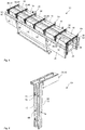
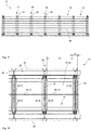
- Fig. 1 shows a perspective view of a shell mold 10 with twelve component chambers 16 arranged next to one another and opposite one another.
- the shell mold 10 comprises a molded base body 26, two rear walls 36 and delimiting bars 64.
- the molded base body 26 has horizontal wall sections 28, 30 and vertical wall sections 28, 32 of the front wall 28 of the molded base body 26 on.
- the component chambers 16 are thus designed for the formation of wall panels, in particular angled wall panels.
- the delimitation bars 64 are each formed from two side walls 38, 40.
- the mechanism for moving the side walls against each other is located inside the delimitation bars, so that the distances a1 and a2 (see also Fig. 12 ) can vary between two side walls.
- the rear walls 36 are shown slightly pivoted, as is necessary for stripping the formwork.
- the formwork is removed without giving away or rotating the formwork.
- the components (not shown) are removed in the position shown and then rotated and placed on a surface.
- FIG. 4 is a perspective view of the perimeter spar 64 of one embodiment Fig. 1 shown.
- the delimitation spar 64 is formed from several side walls 38, 40.
- a storage mechanism 66 which has guide plates 72 with elongated holes 74, is attached inside the delimitation beam 64.
- Guide elements 76 of the guide plates 72 are arranged in these elongated holes 74. These enable the side walls 38, 40 to be moved against one another by shifting the guide elements 76 in the elongated holes 74, whereby the guide plates 72 are moved in the vertical and horizontal directions and finally the side walls 38, 40 connected to the guide plates 72 are also moved.
- Each delimitation spar 64 can contain four guide plates 72, each with two elongated holes 74, in this vertical section.
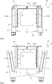
- FIG. 3 shows a cross-section of an embodiment according to FIG Fig. 1 .
- the shell mold 10 is shown in a filling position 84 with vertically aligned rear walls 36.
- the component chamber 16 is thus formed by a plurality of side walls 38, 40, each a section rear wall 38, 42 and the mold base body 26 and the rear wall 36.
- FIG. 3 A representation of the form 10 according to Fig. 3 shows in a demolding position 88 Fig. 4 .
- the rear walls 36 are shown pivoted here.
- the rear walls 36 can be pivoted even further from the position shown, so that the angle between the rear wall 36 and the side walls 40 increases further. All other elements of this embodiment correspond to that of Fig. 3 .
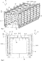
- Fig. 5 shows a perspective view of another embodiment of a mold 10 according to the invention in a filling position 84.
- the mold 10 comprises twelve component chambers 16, each of which is formed from a mold base body 26, a rear wall 36, several side walls 38, 40 and a section rear wall 38, 42.
- the rear wall 36 of all the component chambers 16 arranged on one side of the formwork mold 10 can be designed in one piece. This also applies to the molded body.
- each limiting strut 64 comprises an unlocking device 46 with a locking section 60, 62 and an unlocking section (not visible in this position of the unlocking device 46).
- control lever 44 and one associated unlocking device 46 per rear wall 36, which is preferably arranged in the area of the central component chamber 16.
- an unlocking device 46 and associated control lever 44 can be arranged only in every second component chamber 16, or the number of control levers 44 can differ from the number of unlocking devices 46.
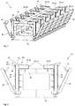
- Fig. 6 shows a cross section through an embodiment according to Fig. 5 .
- the shell mold 10 is shown in a filling position 84, the rear walls 36 being oriented vertically.
- the unlockers 46 are arranged within the delimitation bars 64 and are in a not yet locked position so that the locking section 60 with the nose 62 is still visible.
- the nose 62 of the locking section 60 is arranged on the underside 50 of the unlocker 46.
- the unlocking section 56 with an overhang 58 is not visible, since this is arranged within the delimiting beam 64 and is covered by the side walls 38, 40.
- the unlocker 46 is rotated so that the top 52 of the unlocker 46 runs parallel to the side wall 40.
- Fig. 7 shows an embodiment of the form 10 shown in perspective Fig. 5 for a changed component geometry 12.
- This form form 10 is suitable for small-format angled wall panels.
- the rear walls 36 are shown pivoted outward.
- Each component chamber consists of several side walls 38, 40, each of a section rear wall 42, part of the molded body 26 and part of the rear wall 36.
- the delimitation bars 64 are formed from several side walls 38 or section side walls 40 and each contain an unlocking device 46.
- the control levers 44 are visible.
- a control lever 44 is assigned to each unlocking device 46 or each limiting bar 64, so that their number corresponds.
- FIG. 8 is a perspective cross-section of the embodiment of FIG Fig. 7 shown with pivoted rear walls 36.
- the control levers 44 are arranged on the rear walls 36.
- the unlockers 46 are shown in a rotating position so that only the locking portion 60 with nose 62 is visible.
- the unlocking section 56 with protrusion 58 of the unlocking device 46 is in this position inside the delimitation bar 46 and is covered by the side walls 38, 40.
- the formwork 10 in the embodiment shown is suitable for small-format, angled wall panels, since the section rear walls 38, 40 of the mirrored opposing component chambers 16 are far away from one another and do not touch.
- Fig. 9 shows an embodiment of a form 10 for large-format, angled wall panels. This can be seen in that the section rear walls 38, 42 of the component chambers 16 arranged opposite one another in a mirrored manner. In the position shown, the rear walls 36 are moved so close to the side walls 38 that the control levers 44 already engage in the parking mechanism 66, which is arranged within the delimitation bars 64. The control levers 44 engage in the guide elements 70 (not visible in this view) of the control levers 44. A control lever 44 is assigned to each delimitation beam 64. For a shell mold 10 with twelve component chambers 16 arranged opposite and mirrored next to one another, fourteen control levers 44 and fourteen unlockers 46 are accordingly arranged. A cross section through a form 10 according to Fig. 9 is in Fig. 10 shown.
- Fig. 11 shows a side view of a form of scarf Figures 9 and 10 .
- a side view of a rear wall 36 is shown, the unlockers 46 protruding above.
- An unlocking device 46 is arranged in each of the seven visible delimitation bars 64.
- FIG. 12 An associated section of a plan view of this embodiment of the form 10 according to Fig. 9 is in Fig. 12 shown.
- the detail shows four component chambers 16, only the horizontal wall section 30 of the front wall 28 of the basic molded body 26 of the basic molded body 26 of the shell mold 10 being visible.
- the horizontal wall section 30 is delimited by the side wall 38, ie the section rear wall 42 and two section side walls 40 and has a width a1.
- the storage mechanism 66 is located in the delimitation beam 64 between two side walls 38, 40, the delimitation beam 64 having a width a2.
- the control levers 44 which are attached to the rear wall 36, engage in the limiting beam 64.
- An unlocking device 46 is arranged in each delimitation beam 64.
- Fig. 13 shows a detail view of the vertical section of a delimitation beam 64, which is formed from two side walls 38, 40.
- the storage mechanism 66 is located inside the delimitation beam 64. This is formed from guide plates 42 with elongated holes 74. Guide elements 76 of the guide plates 72 are arranged within these elongated holes 74.
- the storage device includes four guide plates 72 with two elongated holes 74 each. Guide elements 70 for the control lever 44 are also arranged within the delimitation bar 64. These have a circular geometry and can be designed as rollers.
- Another perspective view of the delimitation beam 64 according to FIG Fig. 13 is in Fig. 14 shown. The four guide plates 72 are visible in this view.
- the control lever 44 comprises a sealing section 78 and a control section 80.
- the sealing section 78 is designed in a straight line and is located in the area of the control lever 44 which is closer to the rear wall 36 (not shown).
- the control section 80 is curved.
- the control lever 44 first engages with the control section 80 in the guide elements 70 (not shown) in the parking mechanism 66 (not shown).
- the travel speed of the side walls 36 is controlled via the storage mechanism via the curved control section 80.
- a different curved shape of the control section 80 of the control lever 44 accordingly leads to a different travel speed of the side walls 38.
- the control section 80 can also be partially straight, preferably in the area in which the control section 80 first engages the guide elements 72.
- Fig. 16 shows a further perspective view of such a control lever Fig. 15 .
- the control lever 44 is off Figures 15 and 16 shown again as a side view.
- the rectilinear partial area of the control section 80 at the right end of the control lever 44 is clearly visible in this view.
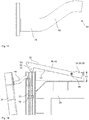
- Fig. 18 is an excerpt from Fig. 10 shown.
- the detailed view shows a section through the delimitation bar 64, the complete unlocking device 46 becoming visible.
- the unlocking device 46 has a rod-shaped base body 48 and two end sections 64.
- One end section 64 here forms the locking section 60, which is formed by a nose 62.
- the nose 62 is attached to the underside 50 of the unlocker 46.
- the other end area 54 of the unlocking device 46 forms an unlocking section 56, this being formed by a protrusion 58.
- This protrusion 58 is located on the upper side 52 of the unlocker 46.
- the unlocker 46 can rotate about an axis of rotation 96.
- the axis of rotation 96 is located near the end region 54 on which the unlocking section 56 is arranged.
- the rear wall 36 of the shell mold 10 is shown slightly inclined so that the control lever 44 does not yet engage with the control section 80 in the storage mechanism 66, ie in the guide elements 70.
- the unlocking device 46 is in a not yet locking position.
- the locking section 60 accordingly protrudes above the side walls 38, and the unlocking section 56 lies in a position within these side walls 38, that is to say within the delimitation beam 64.
- a further embodiment of a shell mold 10 according to the invention is shown in perspective.
- the embodiment shown has no control lever 44 and no unlocking device 46.
- several guide rods 102 are arranged on the rear wall 36, on which several wedges 100 are integrated.
- twelve wedges 100 and twelve associated hooks 98 are therefore required.
- the guide rod 102 with integrated wedges 100 can be moved in the longitudinal direction to the rear wall 96.
- the delimitation bars 64 are also formed by side walls 38, 40.
- FIG. 11 shows a perspective detailed view of the embodiment according to FIG Fig. 19 .
- a section of the rear wall 36 is shown, on which a guide rod 102 and a wedge 100 are visible.
- the guide rod 102 can be displaced in the longitudinal direction of the guide rod 102 in such a way that the wedge 100 moves in the direction of the hook 98.
- the wedge 100 first engages the hook with the smaller cross-sectional area.
- Fig. 21 shows a perspective longitudinal section through Fig. 20 by the hook 98.
- the wedge 100 By moving the guide rod 102 in the longitudinal direction, the wedge 100 can be moved in the direction of the hook 98.
- the hook can be jammed with the wedge to different degrees.
- the contact pressure of the rear wall 36 on the side walls 38 can thus be controlled and optimized via the wedge 100.
- the sealing function can be controlled individually by this contact pressure between the rear wall and the side wall.
- FIGs. 22a to 22c are sectional views through a mounting seat 104 of a component 12, 14 shown.
- the mounting seat 104 which is composed of a threaded sleeve 106 and a thickened anchor block 110.
- the anchor block 110 is cast in the interior of the component 12 and ensures anchoring of the threaded sleeve 106.
- a fixing element 114 is inserted into the holder receptacle 104 for the temporary attachment of the holder receptacle 104 in the formwork 10.
- the fixing element 114 comprises a threaded bolt 116 and a ferromagnetic thin and circular base disk 118.
- the threaded bolt 116 can be screwed into the threaded sleeve 106.
- a receiving area 112 of the front wall 28 has a recess area which can at least partially receive the base plate 118.
- the recess area prevents the position of the mounting receptacle 104 on the front wall 28 from changing.
- the position of the receiving area 112 is selected in such a way that, after the concrete element has been poured, the mounting receptacle is suitable for receiving the center of gravity of the component.
- a magnet 108 is arranged either as a permanent magnet or as an electromagnet, which can fasten the base plate 118 in a non-positive manner and thus fix the holder receptacle. Nonetheless, the base plate 118 can be permanently magnetic in order to adhere to a ferromagnetic receiving area 112.
- FIG 22c the mounting receptacle 104 cast into the component 12, 14 is shown in a sectional view.
- the fixing element 114 can be removed from the holder receptacle 104 and reused.
- a heavy-duty hook can be screwed into the threaded sleeve 106 of the holder receptacle 104 for transport, which serves as a point of application for a load lifting device such as a crane etc. in order to be able to lift the component in the center of gravity and move it in any position without force.
- a plurality of holder receptacles 104 can be provided, with the region of the component 14 around the holder receptacle connected thereto also having a recess region 120 that was effected by the base plate 118.
- the recess area 120 can be used to receive a cover made of plastic, stainless steel or the like, for example, in order to close the holder receptacle 104 after final assembly in order to produce a visible surface.
- the magnet arrangement of the mounting receptacle 104 ensures that the mounting receptacle 104 is positioned exactly for a center of gravity receptacle in the concrete element.
- a free-floating component By recording the center of gravity, a free-floating component can be moved in the assembly phase, for example, parallel to a bed of gravel and placed on it without sideshift, so that a gravel or concrete bed is not shifted and repositioning is possible without effort.
- the holder receptacle 104 can be used in a construction project to fasten further structural parts such as fastenings, railings, receptacles, etc.
Landscapes
- Engineering & Computer Science (AREA)
- Manufacturing & Machinery (AREA)
- Chemical & Material Sciences (AREA)
- Ceramic Engineering (AREA)
- Mechanical Engineering (AREA)
- Moulds, Cores, Or Mandrels (AREA)
Claims (13)
- Moule (10) destiné à fabriquer au moins un élément de construction (12), notamment un élément de construction en béton (14) avec arêtes (18) et/ou chanfreins (20) définis, présentant au moins un coffret d'élément de construction (16) qui est délimité par un corps de base de moule (26) défini par une paroi avant (28), au moins une paroi arrière (36) et plusieurs parois latérales (38) du moule (10), sachant qu'au moins une paroi arrière (36) est conçue de manière mobile pour permettre une ouverture et est montée de préférence de manière à pivoter ou à coulisser, et qu'au moins une paroi latérale (38) est conçue pour être déplaçable, sachant qu'est prévu entre la paroi arrière (36) et la paroi latérale (38) un mécanisme de décoffrage (66) qui provoque, en cas de mouvement d'ouverture de la paroi arrière (36), un déplacement de la paroi latérale (38), caractérisé en ce que ladite au moins une paroi latérale déplaçable (38) est déplacée mécaniquement comme partie du mécanisme de décoffrage (66) par le biais d'un levier de commande (44) monté et disposé sur la paroi arrière (36), et que le levier de commande (44) comprend au moins une section de commande (80) recourbée, destinée à la régulation de la vitesse de déplacement de la paroi latérale (38) ainsi qu'une section d'étanchéité (78) rectiligne destinée à étanchéifier la jonction entre la paroi arrière et la paroi latérale et la commande de la pression d'appui.
- Moule (10) selon la revendication 1, caractérisé en ce qu'au moins deux parois latérales (38) sont conçues pour être déplaçables.
- Moule (10) selon une des revendications précédentes, caractérisé en ce que deux parois latérales opposées (38) d'un coffret d'élément de construction (16) sont déplaçables ou coulissables l'une par rapport à l'autre, si bien qu'un écart (a1) entre les deux parois latérales (38) est variable.
- Moule (10) selon une des revendications précédentes, caractérisé en ce que le moule (10) comprend au moins deux coffrets d'élément de construction (16) adjacents et qu'est disposé entre les coffrets d'éléments de construction (16) un longeron de délimitation (64) contre lequel sont disposées deux parois latérales, sachant qu'une paroi latérale (38) est associée à chaque coffret d'élément de construction (16), sachant que le longeron de délimitation (64) comprend le mécanisme de décoffrage (66) pour déplacer les deux parois latérales (38) l'une par rapport à l'autre.
- Moule (10) selon la revendication 4, caractérisé en ce qu'est disposé dans le longeron de délimitation (64) au moins un crochet (98) qui s'engage dans un évidement de la paroi arrière (36) lors de la fermeture de la paroi arrière (36), sachant qu'est disposée dans ou sur la paroi arrière (36) une tige de guidage (102) avec clavette intégrée (100) qui s'engage de manière détachable dans le crochet (98) et que la tige de guidage (102) est disposée, de manière déplaçable, dans ou sur la paroi arrière (36).
- Moule (10) selon une des revendications précédentes, caractérisé en ce que le mécanisme de décoffrage (66) comprend des éléments de guidage (70) pour guider le levier de commande (44) et comprend notamment des tôles de guidage (72) avec des trous oblongs (74) et des éléments de guidage (76) pour ces trous oblongs (74) par le biais desquels les parois latérales déplaçables (38) sont commandables.
- Moule (10) selon une des revendications précédentes, caractérisé en ce que pour fabriquer un élément de construction coudé (12), la paroi avant (28) du corps de base de moule (26) est conçue coudée et comprend au moins une section de paroi verticale (32) ainsi qu'au moins une section de paroi horizontale (30).
- Moule (10) selon une des revendications précédentes, caractérisé en ce que le moule (10) comprend quatre à seize, de préférence six à quatorze, notamment douze coffrets d'élément de construction (16), sachant que deux rangées de coffrets d'élément de construction (16) adjacents sont disposées de préférence de manière axialement symétriques.
- Moule (10) selon la revendication 8, caractérisé en ce que la paroi arrière (36) de tous les coffrets d'élément de construction adjacents (16) est constituée d'un seul tenant.
- Moule (10) selon une des revendications précédentes, caractérisé en ce qu'est prévue, dans la paroi avant (28), au moins une zone de logement (112) à aimant permanent ou magnétisable et de préférence creusée, dans laquelle peut être disposé temporairement un logement de fixation (104) à sceller, notamment un manchon fileté (106), d'un élément de construction (14), sachant que de préférence la zone de logement (112) est disposée à un endroit de la paroi avant (28) qui correspond à une suspension au centre de gravité du logement de fixation (104) ou d'un positionnement au centre de gravité de plusieurs logements de fixation (104) de l'élément de construction (14).
- Procédé pour remplir et décoffrer un moule (10) selon une des revendications précédentes, sachant qu'après le remplissage dudit au moins un coffret d'élément de construction (16) dans une position de remplissage (84) avec un côté de remplissage (86) horizontalement ouvert vers le haut, le moule (10) reste en position de remplissage (84) jusqu'à ce que le matériau de remplissage (22), de préférence le béton (24), soit au moins partiellement durci, et qu'au moins une paroi latérale (38) soit déplacée pour le décoffrage, au moyen d'un mouvement d'ouverture de la paroi arrière (36), de préférence au moyen d'un pivotement selon un angle α ou d'un basculement.
- Procédé pour remplir et décoffrer un moule (10) selon la revendication 11, caractérisé en ce qu'a lieu, après le durcissement au moins partiel du matériau de remplissage (22) au bout de 8 à 12 heures, notamment moins de 5 heures, un pivotement du moule (10) dans une position de décoffrage (88) de manière à ce que le côté de remplissage (86) soit orienté vers le bas.
- Procédé selon la revendication 12 pour remplir et décoffrer une forme (10), caractérisé en ce que dans la position de décoffrage (88), la paroi arrière (36) est éloignée de l'élément de construction (12) de manière à ouvrir et notamment est pivotée après la dépose du moule (10) sur un support (82), sachant que ledit au moins un levier de commande (44) active le mécanisme de décoffrage (66) et qu'au moins une paroi latérale (38) est éloignée de l'élément de construction (12) et qu'ensuite, le moule (10) est déplacé vers le haut pour le décoffrage.
Priority Applications (1)
| Application Number | Priority Date | Filing Date | Title |
|---|---|---|---|
| PL16182990T PL3147094T3 (pl) | 2015-08-07 | 2016-08-05 | Forma szalunkowa do ściany oporowej |
Applications Claiming Priority (1)
| Application Number | Priority Date | Filing Date | Title |
|---|---|---|---|
| DE102015113077.7A DE102015113077B4 (de) | 2015-08-07 | 2015-08-07 | Schalform für ein Bauelement und Verfahren zum Ausschalen |
Publications (3)
| Publication Number | Publication Date |
|---|---|
| EP3147094A2 EP3147094A2 (fr) | 2017-03-29 |
| EP3147094A3 EP3147094A3 (fr) | 2017-05-10 |
| EP3147094B1 true EP3147094B1 (fr) | 2021-02-24 |
Family
ID=56683751
Family Applications (1)
| Application Number | Title | Priority Date | Filing Date |
|---|---|---|---|
| EP16182990.8A Active EP3147094B1 (fr) | 2015-08-07 | 2016-08-05 | Moule pour mur vertical |
Country Status (4)
| Country | Link |
|---|---|
| EP (1) | EP3147094B1 (fr) |
| DE (1) | DE102015113077B4 (fr) |
| DK (1) | DK3147094T3 (fr) |
| PL (1) | PL3147094T3 (fr) |
Cited By (1)
| Publication number | Priority date | Publication date | Assignee | Title |
|---|---|---|---|---|
| DE102022101978A1 (de) | 2022-01-28 | 2023-08-03 | Robert Thomas Metall- Und Elektrowerke Gmbh & Co. Kg | Betonform |
Families Citing this family (19)
| Publication number | Priority date | Publication date | Assignee | Title |
|---|---|---|---|---|
| CN107088956A (zh) * | 2017-06-28 | 2017-08-25 | 黄河水利委员会黄河水利科学研究院 | 一种组合式圆柱体试件制作模具 |
| CN108005391B (zh) * | 2017-12-29 | 2024-12-13 | 山东大学 | 新型模筑混凝土内置振捣装置 |
| AT520739B1 (de) * | 2018-03-06 | 2019-07-15 | Progress Holding Ag | Schalungsanordnung |
| CN110757626B (zh) * | 2019-10-25 | 2025-03-28 | 颍上晶宫绿建节能建筑有限责任公司 | 一种预制建筑塔基制作模具 |
| CN112008838B (zh) * | 2020-09-21 | 2025-02-25 | 山东明达建筑科技有限公司 | 一种预应力叠合楼板的t型肋组合式生产模具 |
| EP4006266B1 (fr) | 2020-11-30 | 2024-09-04 | Georg Weidner | Dispositifs de maintien pour ancres de transport et ancres de transport |
| CN112476730B (zh) * | 2020-12-15 | 2024-12-31 | 浙江华临建设集团有限公司 | 一种轻骨料混凝土pc构件灌注模具及灌注工艺 |
| CN114311235B (zh) * | 2021-12-24 | 2024-12-31 | 苏州良浦节能新材料股份有限公司 | 一种便于安装固定及拆卸的墙板模具 |
| CN114178765B (zh) * | 2021-12-29 | 2024-02-06 | 山东华中重钢有限公司 | 一种h型钢自动组立机 |
| CN114474304B (zh) * | 2022-02-14 | 2023-07-21 | 中交上海航道局有限公司 | 一种大型圆弧多孔薄壁素混凝土结构的浇筑设备 |
| CN115741949A (zh) * | 2022-12-02 | 2023-03-07 | 辽宁工程技术大学 | 一种预制混凝土构件墙式浇灌型模 |
| CN116422778B (zh) * | 2023-03-03 | 2025-11-04 | 中国化学工程第三建设有限公司 | 一种防撞柱制作用组合模具 |
| CN116494369B (zh) * | 2023-04-23 | 2025-08-15 | 国网安徽省电力有限公司经济技术研究院 | 一种pec构件成型加工装置 |
| CN116394380B (zh) * | 2023-06-07 | 2023-08-22 | 山西二建集团有限公司 | 建筑用钢结构预制模板 |
| CN117103429B (zh) * | 2023-09-20 | 2024-11-05 | 安徽省高迪循环经济产业园股份有限公司 | 一种带有端模加固组件的预制t梁及方法 |
| CN118404681B (zh) * | 2024-06-27 | 2024-08-23 | 山西路桥模板科技有限公司 | 一种t梁钢模板及其使用方法 |
| CN119188970A (zh) * | 2024-10-12 | 2024-12-27 | 中国二十二冶集团有限公司 | 电梯井、集水坑预制模具及预制方法 |
| CN120170872B (zh) * | 2025-05-23 | 2025-08-05 | 甘肃金昌市镍城水泥制品有限责任公司 | 一种水泥预制墙体生产模具及生产方法 |
| CN120620455B (zh) * | 2025-08-18 | 2025-11-18 | 烟台海珐电气科技有限公司 | 一种一体式光伏发电墙板成型制造装置 |
Family Cites Families (20)
| Publication number | Priority date | Publication date | Assignee | Title |
|---|---|---|---|---|
| US796638A (en) * | 1905-01-20 | 1905-08-08 | Frank J Hall | Molding device. |
| DE274068C (de) * | 1912-10-02 | 1914-05-13 | Form zur Herstellung von Beton-Bauwerkstücken u. dgl. aus aneinandergereihten, offenen Formteilen | |
| DE1584525B1 (de) * | 1966-08-16 | 1971-01-14 | Armin Kleiber | Batterieschalung |
| DD68847A1 (de) * | 1968-06-24 | 1969-09-05 | Ingolf Kotte | Verfahren und vorrichtung zur herstellung von fertigteilen, insbesondere von betonfertigteilen |
| FR2163897A5 (fr) * | 1971-12-06 | 1973-07-27 | Coignet Edmond Const | |
| DE2430009C2 (de) * | 1974-06-22 | 1984-06-28 | Lorenz 4600 Dortmund Kesting | Verfahren und Vorrichtung zum Entschalen von Großtafeln aus Stahlbeton |
| DD129197A1 (de) * | 1976-12-30 | 1978-01-04 | Dietmar Ebisch | Verfahren und vorrichtung zur herstellung von raeumlichen betonfertigteilen,insbesondere von eckelementen fuer waende |
| DE7730741U1 (de) * | 1977-10-05 | 1978-06-01 | Katzer & Kramer, 4800 Bielefeld | Vorrichtung zur herstellung von winkelstuetzen aus beton, wie sichtbeton, strukturbeton oder waschbeton |
| DD229069A1 (de) * | 1984-11-20 | 1985-10-30 | Bauakademie Ddr | Vorrichtung zum abziehen von seitenschalungen |
| DD243237A1 (de) * | 1985-12-13 | 1987-02-25 | Bauakademie Ddr | Vorrichtung zum bewegen der stirnteile von vertikalen formraeumen |
| SU1412970A1 (ru) * | 1987-01-07 | 1988-07-30 | Молдавский Научно-Исследовательский И Проектно-Конструкторский Институт Строительных Материалов | Кассетна установка дл изготовлени строительных изделий |
| JP2523754Y2 (ja) * | 1990-04-13 | 1997-01-29 | 松岡コンクリート工業株式会社 | L形コンクリートブロツクの成形型枠 |
| JP3086571B2 (ja) * | 1993-09-02 | 2000-09-11 | 株式会社カイエーテクノ | 可変勾配l型擁壁ブロック製造用型枠 |
| JPH1177646A (ja) * | 1997-07-11 | 1999-03-23 | Oike:Kk | 耐久性型枠およびコンクリート製ユニットの製造方法 |
| DE10158949A1 (de) * | 2001-12-03 | 2003-06-12 | Prinzing Georg Gmbh Co Kg | Verfahren und Vorrichtung zum Herstellen von Betonteilen |
| DE202004015326U1 (de) * | 2004-09-30 | 2006-02-02 | Rampf Formen Gmbh | Form zur maschinellen Herstellung von Formkörpern |
| DE102007006907B4 (de) * | 2007-02-13 | 2008-11-27 | Peri Gmbh | Rahmenschalungssysteme für die Ausbildung von Ecken und T-Kreuzungen unter Verwendung von Rahmenschalelementen mit mittig aufgereihten Ankerlöchern |
| DE102007019383B4 (de) * | 2007-04-23 | 2009-01-08 | Ratec Maschinenentwicklungs- Und Verwaltungs-Gmbh | Batterieschalung zur vertikalen Fertigung von flächigen Betonfertigteilen |
| DE112011101313A5 (de) * | 2010-04-14 | 2013-01-24 | Kobra Formen Gmbh | Schalungsform und Verfahren zur Herstellung von Beton-Winkelsteinen |
| DE102013204999A1 (de) * | 2012-09-28 | 2014-04-03 | Harsco Infrastructure Services Gmbh | Schaltafel mit Kunststoffschalhaut |
-
2015
- 2015-08-07 DE DE102015113077.7A patent/DE102015113077B4/de active Active
-
2016
- 2016-08-05 PL PL16182990T patent/PL3147094T3/pl unknown
- 2016-08-05 DK DK16182990.8T patent/DK3147094T3/da active
- 2016-08-05 EP EP16182990.8A patent/EP3147094B1/fr active Active
Non-Patent Citations (1)
| Title |
|---|
| None * |
Cited By (1)
| Publication number | Priority date | Publication date | Assignee | Title |
|---|---|---|---|---|
| DE102022101978A1 (de) | 2022-01-28 | 2023-08-03 | Robert Thomas Metall- Und Elektrowerke Gmbh & Co. Kg | Betonform |
Also Published As
| Publication number | Publication date |
|---|---|
| DK3147094T3 (da) | 2021-08-30 |
| EP3147094A2 (fr) | 2017-03-29 |
| PL3147094T3 (pl) | 2021-09-20 |
| EP3147094A3 (fr) | 2017-05-10 |
| DE102015113077A1 (de) | 2017-02-09 |
| DE102015113077B4 (de) | 2021-06-10 |
Similar Documents
| Publication | Publication Date | Title |
|---|---|---|
| EP3147094B1 (fr) | Moule pour mur vertical | |
| EP2083977B1 (fr) | Système de coffrage pour le bétonnage d'éléments préfabriqués, comprenant un coffrage extérieur et un coffrage central | |
| DE112012004108T5 (de) | Verbaukasten-system und -verfahren | |
| EP2443299B1 (fr) | Tête de décintrement pour système de coffrage de dalles et système de coffrage de dalles | |
| EP2480735A1 (fr) | Dispositif de décoffrage | |
| WO2019025513A1 (fr) | Procédé de fabrication d'un élément de plafond et coffrage de plafond | |
| EP3572198B1 (fr) | Coffrage central pour un système de coffrage destiné à bétonner un corps de cloche | |
| DE10018212A1 (de) | Verfahren und Vorrichtung zur Herstellung von biegesteifen Beton- Trägerelementen | |
| EP4092219A1 (fr) | Tete de support a hauteur de support abaissable pour support de coffrage | |
| DE1810310A1 (de) | Verfahren und Einrichtung zur Herstellung eines Stahlbetontragwerkes | |
| DE3501125A1 (de) | Verfahren zur herstellung einer mehrseitigen senkrechten betonwand und anordnung zur durchfuehrung des verfahrens | |
| LU502197B1 (en) | Bauverfahren zum Gießen von hochfestem und wasserundurchlässigem Beton sowie Vorrichtung desselben | |
| EP4069919B1 (fr) | Coffrage pour generer une porte ou fenetre dans un mur ou dalle en beton | |
| EP3330448B1 (fr) | Dispositif et procédé de raccordement de deux composants dans une orientation déterminée relative ainsi que construction en béton | |
| EP4051472B1 (fr) | Dispositif de coffrage | |
| WO2004065087A2 (fr) | Coffrage rabattable | |
| EP2570568B1 (fr) | Tête décintrable pour un système de coffrage de plafond et procédé de retrait d'éléments de coffrage de plafond | |
| DE202023102444U1 (de) | Mobiles Umformwerkzeug für vor Ort gegossene integrale Rohrgräben | |
| WO2014020009A1 (fr) | Dispositif de fabrication d'une cellule préfabriquée dans une construction monolithique | |
| DE202021105440U1 (de) | Vorrichtung zur Herstellung eines Bauteils aus Sichtbeton | |
| DE2458486A1 (de) | Verfahren zur herstellung eines betonformsteins fuer den wasserbau und anlage zur durchfuehrung dieses verfahrens | |
| DE102019004479B4 (de) | Tor und Verfahren zu dessen Herstellung | |
| DE2808644C3 (de) | Vorrichtung zum Gießen von Betonbauelementen | |
| DE3114122C2 (de) | Bausatz, bestehend aus einem Betonrahmen für die Aufnahme eines Kellerfensters, einem mit diesem zu verbindenden Lichtschachtunterteil und Verbindungsmitteln sowie Vorrichtung zur Herstellung eines Betonrahmens für einen solchen Bausatz | |
| DE202025000778U1 (de) | Schalungselement und Schalungssystem |
Legal Events
| Date | Code | Title | Description |
|---|---|---|---|
| PUAI | Public reference made under article 153(3) epc to a published international application that has entered the european phase |
Free format text: ORIGINAL CODE: 0009012 |
|
| STAA | Information on the status of an ep patent application or granted ep patent |
Free format text: STATUS: THE APPLICATION HAS BEEN PUBLISHED |
|
| AK | Designated contracting states |
Kind code of ref document: A2 Designated state(s): AL AT BE BG CH CY CZ DE DK EE ES FI FR GB GR HR HU IE IS IT LI LT LU LV MC MK MT NL NO PL PT RO RS SE SI SK SM TR |
|
| AX | Request for extension of the european patent |
Extension state: BA ME |
|
| PUAL | Search report despatched |
Free format text: ORIGINAL CODE: 0009013 |
|
| AK | Designated contracting states |
Kind code of ref document: A3 Designated state(s): AL AT BE BG CH CY CZ DE DK EE ES FI FR GB GR HR HU IE IS IT LI LT LU LV MC MK MT NL NO PL PT RO RS SE SI SK SM TR |
|
| AX | Request for extension of the european patent |
Extension state: BA ME |
|
| RIC1 | Information provided on ipc code assigned before grant |
Ipc: B28B 7/00 20060101AFI20170404BHEP Ipc: B28B 7/24 20060101ALI20170404BHEP Ipc: B28B 7/02 20060101ALI20170404BHEP |
|
| STAA | Information on the status of an ep patent application or granted ep patent |
Free format text: STATUS: REQUEST FOR EXAMINATION WAS MADE |
|
| 17P | Request for examination filed |
Effective date: 20171110 |
|
| RBV | Designated contracting states (corrected) |
Designated state(s): AL AT BE BG CH CY CZ DE DK EE ES FI FR GB GR HR HU IE IS IT LI LT LU LV MC MK MT NL NO PL PT RO RS SE SI SK SM TR |
|
| STAA | Information on the status of an ep patent application or granted ep patent |
Free format text: STATUS: EXAMINATION IS IN PROGRESS |
|
| 17Q | First examination report despatched |
Effective date: 20200228 |
|
| GRAP | Despatch of communication of intention to grant a patent |
Free format text: ORIGINAL CODE: EPIDOSNIGR1 |
|
| STAA | Information on the status of an ep patent application or granted ep patent |
Free format text: STATUS: GRANT OF PATENT IS INTENDED |
|
| RIC1 | Information provided on ipc code assigned before grant |
Ipc: B28B 7/24 20060101ALI20200902BHEP Ipc: B28B 7/00 20060101AFI20200902BHEP |
|
| INTG | Intention to grant announced |
Effective date: 20200929 |
|
| GRAS | Grant fee paid |
Free format text: ORIGINAL CODE: EPIDOSNIGR3 |
|
| GRAA | (expected) grant |
Free format text: ORIGINAL CODE: 0009210 |
|
| STAA | Information on the status of an ep patent application or granted ep patent |
Free format text: STATUS: THE PATENT HAS BEEN GRANTED |
|
| AK | Designated contracting states |
Kind code of ref document: B1 Designated state(s): AL AT BE BG CH CY CZ DE DK EE ES FI FR GB GR HR HU IE IS IT LI LT LU LV MC MK MT NL NO PL PT RO RS SE SI SK SM TR |
|
| RAP1 | Party data changed (applicant data changed or rights of an application transferred) |
Owner name: LITHONPLUS GMBH & CO. KG |
|
| REG | Reference to a national code |
Ref country code: CH Ref legal event code: EP |
|
| REG | Reference to a national code |
Ref country code: DE Ref legal event code: R096 Ref document number: 502016012426 Country of ref document: DE |
|
| REG | Reference to a national code |
Ref country code: AT Ref legal event code: REF Ref document number: 1363878 Country of ref document: AT Kind code of ref document: T Effective date: 20210315 |
|
| REG | Reference to a national code |
Ref country code: IE Ref legal event code: FG4D Free format text: LANGUAGE OF EP DOCUMENT: GERMAN |
|
| REG | Reference to a national code |
Ref country code: LT Ref legal event code: MG9D |
|
| REG | Reference to a national code |
Ref country code: NL Ref legal event code: FP |
|
| PG25 | Lapsed in a contracting state [announced via postgrant information from national office to epo] |
Ref country code: PT Free format text: LAPSE BECAUSE OF FAILURE TO SUBMIT A TRANSLATION OF THE DESCRIPTION OR TO PAY THE FEE WITHIN THE PRESCRIBED TIME-LIMIT Effective date: 20210624 Ref country code: NO Free format text: LAPSE BECAUSE OF FAILURE TO SUBMIT A TRANSLATION OF THE DESCRIPTION OR TO PAY THE FEE WITHIN THE PRESCRIBED TIME-LIMIT Effective date: 20210524 Ref country code: BG Free format text: LAPSE BECAUSE OF FAILURE TO SUBMIT A TRANSLATION OF THE DESCRIPTION OR TO PAY THE FEE WITHIN THE PRESCRIBED TIME-LIMIT Effective date: 20210524 Ref country code: HR Free format text: LAPSE BECAUSE OF FAILURE TO SUBMIT A TRANSLATION OF THE DESCRIPTION OR TO PAY THE FEE WITHIN THE PRESCRIBED TIME-LIMIT Effective date: 20210224 Ref country code: GR Free format text: LAPSE BECAUSE OF FAILURE TO SUBMIT A TRANSLATION OF THE DESCRIPTION OR TO PAY THE FEE WITHIN THE PRESCRIBED TIME-LIMIT Effective date: 20210525 Ref country code: FI Free format text: LAPSE BECAUSE OF FAILURE TO SUBMIT A TRANSLATION OF THE DESCRIPTION OR TO PAY THE FEE WITHIN THE PRESCRIBED TIME-LIMIT Effective date: 20210224 Ref country code: LT Free format text: LAPSE BECAUSE OF FAILURE TO SUBMIT A TRANSLATION OF THE DESCRIPTION OR TO PAY THE FEE WITHIN THE PRESCRIBED TIME-LIMIT Effective date: 20210224 |
|
| REG | Reference to a national code |
Ref country code: DK Ref legal event code: T3 Effective date: 20210823 |
|
| PG25 | Lapsed in a contracting state [announced via postgrant information from national office to epo] |
Ref country code: RS Free format text: LAPSE BECAUSE OF FAILURE TO SUBMIT A TRANSLATION OF THE DESCRIPTION OR TO PAY THE FEE WITHIN THE PRESCRIBED TIME-LIMIT Effective date: 20210224 Ref country code: LV Free format text: LAPSE BECAUSE OF FAILURE TO SUBMIT A TRANSLATION OF THE DESCRIPTION OR TO PAY THE FEE WITHIN THE PRESCRIBED TIME-LIMIT Effective date: 20210224 Ref country code: SE Free format text: LAPSE BECAUSE OF FAILURE TO SUBMIT A TRANSLATION OF THE DESCRIPTION OR TO PAY THE FEE WITHIN THE PRESCRIBED TIME-LIMIT Effective date: 20210224 |
|
| PG25 | Lapsed in a contracting state [announced via postgrant information from national office to epo] |
Ref country code: IS Free format text: LAPSE BECAUSE OF FAILURE TO SUBMIT A TRANSLATION OF THE DESCRIPTION OR TO PAY THE FEE WITHIN THE PRESCRIBED TIME-LIMIT Effective date: 20210624 |
|
| PG25 | Lapsed in a contracting state [announced via postgrant information from national office to epo] |
Ref country code: SM Free format text: LAPSE BECAUSE OF FAILURE TO SUBMIT A TRANSLATION OF THE DESCRIPTION OR TO PAY THE FEE WITHIN THE PRESCRIBED TIME-LIMIT Effective date: 20210224 Ref country code: EE Free format text: LAPSE BECAUSE OF FAILURE TO SUBMIT A TRANSLATION OF THE DESCRIPTION OR TO PAY THE FEE WITHIN THE PRESCRIBED TIME-LIMIT Effective date: 20210224 |
|
| REG | Reference to a national code |
Ref country code: DE Ref legal event code: R097 Ref document number: 502016012426 Country of ref document: DE |
|
| PG25 | Lapsed in a contracting state [announced via postgrant information from national office to epo] |
Ref country code: SK Free format text: LAPSE BECAUSE OF FAILURE TO SUBMIT A TRANSLATION OF THE DESCRIPTION OR TO PAY THE FEE WITHIN THE PRESCRIBED TIME-LIMIT Effective date: 20210224 Ref country code: ES Free format text: LAPSE BECAUSE OF FAILURE TO SUBMIT A TRANSLATION OF THE DESCRIPTION OR TO PAY THE FEE WITHIN THE PRESCRIBED TIME-LIMIT Effective date: 20210224 Ref country code: RO Free format text: LAPSE BECAUSE OF FAILURE TO SUBMIT A TRANSLATION OF THE DESCRIPTION OR TO PAY THE FEE WITHIN THE PRESCRIBED TIME-LIMIT Effective date: 20210224 |
|
| PLBE | No opposition filed within time limit |
Free format text: ORIGINAL CODE: 0009261 |
|
| STAA | Information on the status of an ep patent application or granted ep patent |
Free format text: STATUS: NO OPPOSITION FILED WITHIN TIME LIMIT |
|
| PG25 | Lapsed in a contracting state [announced via postgrant information from national office to epo] |
Ref country code: AL Free format text: LAPSE BECAUSE OF FAILURE TO SUBMIT A TRANSLATION OF THE DESCRIPTION OR TO PAY THE FEE WITHIN THE PRESCRIBED TIME-LIMIT Effective date: 20210224 |
|
| 26N | No opposition filed |
Effective date: 20211125 |
|
| PG25 | Lapsed in a contracting state [announced via postgrant information from national office to epo] |
Ref country code: SI Free format text: LAPSE BECAUSE OF FAILURE TO SUBMIT A TRANSLATION OF THE DESCRIPTION OR TO PAY THE FEE WITHIN THE PRESCRIBED TIME-LIMIT Effective date: 20210224 |
|
| PG25 | Lapsed in a contracting state [announced via postgrant information from national office to epo] |
Ref country code: MC Free format text: LAPSE BECAUSE OF FAILURE TO SUBMIT A TRANSLATION OF THE DESCRIPTION OR TO PAY THE FEE WITHIN THE PRESCRIBED TIME-LIMIT Effective date: 20210224 |
|
| GBPC | Gb: european patent ceased through non-payment of renewal fee |
Effective date: 20210805 |
|
| PG25 | Lapsed in a contracting state [announced via postgrant information from national office to epo] |
Ref country code: IT Free format text: LAPSE BECAUSE OF FAILURE TO SUBMIT A TRANSLATION OF THE DESCRIPTION OR TO PAY THE FEE WITHIN THE PRESCRIBED TIME-LIMIT Effective date: 20210224 |
|
| PG25 | Lapsed in a contracting state [announced via postgrant information from national office to epo] |
Ref country code: IS Free format text: LAPSE BECAUSE OF FAILURE TO SUBMIT A TRANSLATION OF THE DESCRIPTION OR TO PAY THE FEE WITHIN THE PRESCRIBED TIME-LIMIT Effective date: 20210624 |
|
| PG25 | Lapsed in a contracting state [announced via postgrant information from national office to epo] |
Ref country code: IE Free format text: LAPSE BECAUSE OF NON-PAYMENT OF DUE FEES Effective date: 20210805 Ref country code: GB Free format text: LAPSE BECAUSE OF NON-PAYMENT OF DUE FEES Effective date: 20210805 |
|
| PG25 | Lapsed in a contracting state [announced via postgrant information from national office to epo] |
Ref country code: HU Free format text: LAPSE BECAUSE OF FAILURE TO SUBMIT A TRANSLATION OF THE DESCRIPTION OR TO PAY THE FEE WITHIN THE PRESCRIBED TIME-LIMIT; INVALID AB INITIO Effective date: 20160805 |
|
| PG25 | Lapsed in a contracting state [announced via postgrant information from national office to epo] |
Ref country code: CY Free format text: LAPSE BECAUSE OF FAILURE TO SUBMIT A TRANSLATION OF THE DESCRIPTION OR TO PAY THE FEE WITHIN THE PRESCRIBED TIME-LIMIT Effective date: 20210224 |
|
| P01 | Opt-out of the competence of the unified patent court (upc) registered |
Effective date: 20230613 |
|
| PG25 | Lapsed in a contracting state [announced via postgrant information from national office to epo] |
Ref country code: MK Free format text: LAPSE BECAUSE OF FAILURE TO SUBMIT A TRANSLATION OF THE DESCRIPTION OR TO PAY THE FEE WITHIN THE PRESCRIBED TIME-LIMIT Effective date: 20210224 |
|
| PG25 | Lapsed in a contracting state [announced via postgrant information from national office to epo] |
Ref country code: TR Free format text: LAPSE BECAUSE OF FAILURE TO SUBMIT A TRANSLATION OF THE DESCRIPTION OR TO PAY THE FEE WITHIN THE PRESCRIBED TIME-LIMIT Effective date: 20210224 |
|
| PG25 | Lapsed in a contracting state [announced via postgrant information from national office to epo] |
Ref country code: MT Free format text: LAPSE BECAUSE OF FAILURE TO SUBMIT A TRANSLATION OF THE DESCRIPTION OR TO PAY THE FEE WITHIN THE PRESCRIBED TIME-LIMIT Effective date: 20210224 |
|
| PGFP | Annual fee paid to national office [announced via postgrant information from national office to epo] |
Ref country code: LU Payment date: 20250820 Year of fee payment: 10 Ref country code: NL Payment date: 20250821 Year of fee payment: 10 |
|
| PGFP | Annual fee paid to national office [announced via postgrant information from national office to epo] |
Ref country code: DK Payment date: 20250821 Year of fee payment: 10 Ref country code: DE Payment date: 20250729 Year of fee payment: 10 |
|
| PGFP | Annual fee paid to national office [announced via postgrant information from national office to epo] |
Ref country code: PL Payment date: 20250728 Year of fee payment: 10 |
|
| PGFP | Annual fee paid to national office [announced via postgrant information from national office to epo] |
Ref country code: BE Payment date: 20250820 Year of fee payment: 10 |
|
| PGFP | Annual fee paid to national office [announced via postgrant information from national office to epo] |
Ref country code: AT Payment date: 20250819 Year of fee payment: 10 Ref country code: FR Payment date: 20250821 Year of fee payment: 10 |
|
| PGFP | Annual fee paid to national office [announced via postgrant information from national office to epo] |
Ref country code: CH Payment date: 20250901 Year of fee payment: 10 |
|
| PGFP | Annual fee paid to national office [announced via postgrant information from national office to epo] |
Ref country code: CZ Payment date: 20250723 Year of fee payment: 10 |