EP3147110A1 - Verbundstoffmaterialpositionierungsverfahren - Google Patents
Verbundstoffmaterialpositionierungsverfahren Download PDFInfo
- Publication number
- EP3147110A1 EP3147110A1 EP16190548.4A EP16190548A EP3147110A1 EP 3147110 A1 EP3147110 A1 EP 3147110A1 EP 16190548 A EP16190548 A EP 16190548A EP 3147110 A1 EP3147110 A1 EP 3147110A1
- Authority
- EP
- European Patent Office
- Prior art keywords
- tapes
- ply boundary
- ply
- oblique
- boundary
- Prior art date
- Legal status (The legal status is an assumption and is not a legal conclusion. Google has not performed a legal analysis and makes no representation as to the accuracy of the status listed.)
- Granted
Links
Images



Classifications
-
- B—PERFORMING OPERATIONS; TRANSPORTING
- B29—WORKING OF PLASTICS; WORKING OF SUBSTANCES IN A PLASTIC STATE IN GENERAL
- B29C—SHAPING OR JOINING OF PLASTICS; SHAPING OF MATERIAL IN A PLASTIC STATE, NOT OTHERWISE PROVIDED FOR; AFTER-TREATMENT OF THE SHAPED PRODUCTS, e.g. REPAIRING
- B29C70/00—Shaping composites, i.e. plastics material comprising reinforcements, fillers or preformed parts, e.g. inserts
- B29C70/04—Shaping composites, i.e. plastics material comprising reinforcements, fillers or preformed parts, e.g. inserts comprising reinforcements only, e.g. self-reinforcing plastics
- B29C70/28—Shaping operations therefor
- B29C70/30—Shaping by lay-up, i.e. applying fibres, tape or broadsheet on a mould, former or core; Shaping by spray-up, i.e. spraying of fibres on a mould, former or core
- B29C70/38—Automated lay-up, e.g. using robots, laying filaments according to predetermined patterns
- B29C70/386—Automated tape laying [ATL]
-
- B—PERFORMING OPERATIONS; TRANSPORTING
- B29—WORKING OF PLASTICS; WORKING OF SUBSTANCES IN A PLASTIC STATE IN GENERAL
- B29C—SHAPING OR JOINING OF PLASTICS; SHAPING OF MATERIAL IN A PLASTIC STATE, NOT OTHERWISE PROVIDED FOR; AFTER-TREATMENT OF THE SHAPED PRODUCTS, e.g. REPAIRING
- B29C70/00—Shaping composites, i.e. plastics material comprising reinforcements, fillers or preformed parts, e.g. inserts
- B29C70/04—Shaping composites, i.e. plastics material comprising reinforcements, fillers or preformed parts, e.g. inserts comprising reinforcements only, e.g. self-reinforcing plastics
- B29C70/28—Shaping operations therefor
- B29C70/30—Shaping by lay-up, i.e. applying fibres, tape or broadsheet on a mould, former or core; Shaping by spray-up, i.e. spraying of fibres on a mould, former or core
- B29C70/32—Shaping by lay-up, i.e. applying fibres, tape or broadsheet on a mould, former or core; Shaping by spray-up, i.e. spraying of fibres on a mould, former or core on a rotating mould, former or core
-
- B—PERFORMING OPERATIONS; TRANSPORTING
- B29—WORKING OF PLASTICS; WORKING OF SUBSTANCES IN A PLASTIC STATE IN GENERAL
- B29C—SHAPING OR JOINING OF PLASTICS; SHAPING OF MATERIAL IN A PLASTIC STATE, NOT OTHERWISE PROVIDED FOR; AFTER-TREATMENT OF THE SHAPED PRODUCTS, e.g. REPAIRING
- B29C70/00—Shaping composites, i.e. plastics material comprising reinforcements, fillers or preformed parts, e.g. inserts
- B29C70/04—Shaping composites, i.e. plastics material comprising reinforcements, fillers or preformed parts, e.g. inserts comprising reinforcements only, e.g. self-reinforcing plastics
- B29C70/28—Shaping operations therefor
- B29C70/54—Component parts, details or accessories; Auxiliary operations, e.g. feeding or storage of prepregs or SMC after impregnation or during ageing
- B29C70/545—Perforating, cutting or machining during or after moulding
-
- B—PERFORMING OPERATIONS; TRANSPORTING
- B29—WORKING OF PLASTICS; WORKING OF SUBSTANCES IN A PLASTIC STATE IN GENERAL
- B29C—SHAPING OR JOINING OF PLASTICS; SHAPING OF MATERIAL IN A PLASTIC STATE, NOT OTHERWISE PROVIDED FOR; AFTER-TREATMENT OF THE SHAPED PRODUCTS, e.g. REPAIRING
- B29C2793/00—Shaping techniques involving a cutting or machining operation
- B29C2793/0027—Cutting off
-
- B—PERFORMING OPERATIONS; TRANSPORTING
- B29—WORKING OF PLASTICS; WORKING OF SUBSTANCES IN A PLASTIC STATE IN GENERAL
- B29C—SHAPING OR JOINING OF PLASTICS; SHAPING OF MATERIAL IN A PLASTIC STATE, NOT OTHERWISE PROVIDED FOR; AFTER-TREATMENT OF THE SHAPED PRODUCTS, e.g. REPAIRING
- B29C2793/00—Shaping techniques involving a cutting or machining operation
- B29C2793/0081—Shaping techniques involving a cutting or machining operation before shaping
-
- Y—GENERAL TAGGING OF NEW TECHNOLOGICAL DEVELOPMENTS; GENERAL TAGGING OF CROSS-SECTIONAL TECHNOLOGIES SPANNING OVER SEVERAL SECTIONS OF THE IPC; TECHNICAL SUBJECTS COVERED BY FORMER USPC CROSS-REFERENCE ART COLLECTIONS [XRACs] AND DIGESTS
- Y10—TECHNICAL SUBJECTS COVERED BY FORMER USPC
- Y10T—TECHNICAL SUBJECTS COVERED BY FORMER US CLASSIFICATION
- Y10T156/00—Adhesive bonding and miscellaneous chemical manufacture
- Y10T156/10—Methods of surface bonding and/or assembly therefor
- Y10T156/1052—Methods of surface bonding and/or assembly therefor with cutting, punching, tearing or severing
- Y10T156/1062—Prior to assembly
- Y10T156/1075—Prior to assembly of plural laminae from single stock and assembling to each other or to additional lamina
- Y10T156/1077—Applying plural cut laminae to single face of additional lamina
-
- Y—GENERAL TAGGING OF NEW TECHNOLOGICAL DEVELOPMENTS; GENERAL TAGGING OF CROSS-SECTIONAL TECHNOLOGIES SPANNING OVER SEVERAL SECTIONS OF THE IPC; TECHNICAL SUBJECTS COVERED BY FORMER USPC CROSS-REFERENCE ART COLLECTIONS [XRACs] AND DIGESTS
- Y10—TECHNICAL SUBJECTS COVERED BY FORMER USPC
- Y10T—TECHNICAL SUBJECTS COVERED BY FORMER US CLASSIFICATION
- Y10T156/00—Adhesive bonding and miscellaneous chemical manufacture
- Y10T156/17—Surface bonding means and/or assemblymeans with work feeding or handling means
Definitions
- the present invention generally relates to a system and method of fabricating a composite item. More particularly, the present invention pertains to a system for auto lamination of a composite and its method of use.
- Composite items are typically fabricated from multiple layers or plies. These plies generally include a variety of materials such as carbon fiber, various other fibers, metal films or foils, and the like.
- the plies may be pre-impregnated (if fiber) or coated (if foil) with a resin and are often dispensed from a roll or spool.
- the composite ply material is referred to as "tape" and may or may not include a backing layer.
- This backing generally prevents resin coated or pre-impregnated ply material (prepreg) from adhering to itself and aids in handling the tape as the tape is applied to the tool and the layup.
- the tape is applied to tool in a multitude of courses laid side by side to form a ply. The wider this tape is, the fewer the number of courses that need be applied. As such, using wider tape generally increases lay-down rates and speeds fabrication of the composite item. However, increasing the width of the tape increases the size and complexity of the tape cutting device.
- An embodiment of the present invention relates to a method of applying a course on a layup mold.
- a ply boundary that defines a ply area on the layup mold is determined and a tape of composite material is applied on the ply area at an oblique angle relative to the ply boundary.
- a leading edge of the tape is butt cut and the leading edge and the ply boundary essentially converge.
- a trailing edge is generated. The trailing edge is a butt cut and the trailing edge and the ply boundary essentially converge.
- Another embodiment of the present invention pertains to a method of fabricating a transition zone in a composite item.
- the transition zone defines an area that begins at a first skin gauge and ends at a second skin gauge.
- the transition zone includes a first oblique ply boundary that is offset from a second oblique ply boundary.
- a first set of tapes of composite material is applied across the first oblique ply boundary.
- Each of the first set of tapes includes a respective end that is butt cut and each of the first set of tapes includes a respective centerline. For each of the first set of tapes, the respective end and the respective centerline essentially converge upon the first oblique ply boundary.
- a second set of tapes of composite material is applied across the second oblique ply boundary.
- Each of the second set of tapes includes a respective end that is butt cut and each of the second set of tapes includes a respective centerline.
- the respective end and the respective centerline essentially converge upon the second oblique ply boundary.
- the respective ends of the second set of tapes are offset from the respective ends of the first set of tapes to generate a crenulated pattern.
- Yet another embodiment of the present invention relates to a computer readable medium on which is embedded computer software comprising a set of instructions for executing a method of applying a course on a layup mold.
- a ply boundary that defines a ply area on the layup mold is determined and a tape of composite material is applied on the ply area at an oblique angle relative to the ply boundary.
- a leading edge of the tape is butt cut and the leading edge and the ply boundary essentially converge.
- a trailing edge is generated. The trailing edge is a butt cut and the trailing edge and the ply boundary essentially converge.
- Yet another embodiment of the present invention pertains to a computer readable medium on which is embedded computer software comprising a set of instructions for executing a method of fabricating a transition zone in a composite item.
- the transition zone defines an area that begins at a first skin gauge and ends at a second skin gauge.
- the transition zone includes a first oblique ply boundary that is offset from a second oblique ply boundary.
- a first set of tapes of composite material is applied across the first oblique ply boundary.
- Each of the first set of tapes includes a respective end that is butt cut and each of the first set of tapes includes a respective centerline.
- each of the first set of tapes the respective end and the respective centerline essentially converge upon the first oblique ply boundary.
- a second set of tapes of composite material is applied across the second oblique ply boundary.
- Each of the second set of tapes includes a respective end that is butt cut and each of the second set of tapes includes a respective centerline.
- the respective end and the respective centerline essentially converge upon the second oblique ply boundary.
- the respective ends of the second set of tapes are offset from the respective ends of the first set of tapes to generate a crenulated pattern.
- Yet another embodiment of the present invention relates to an apparatus for applying a course on a layup mold.
- the apparatus includes a means for determining a ply boundary that defines a ply area on the layup mold and a means for applying a tape of composite material on the ply area at an oblique angle relative to the ply boundary.
- a leading edge of the tape is butt cut and the leading edge and the ply boundary essentially converge.
- the apparatus includes a means for generating a trailing edge. The trailing edge is a butt cut and the trailing edge and the ply boundary essentially converge.
- Yet another embodiment of the present invention pertains to an apparatus for fabricating a transition zone in a composite item.
- the transition zone defines an area that begins at a first skin gauge and ends at a second skin gauge.
- the transition zone includes a first oblique ply boundary that is offset from a second oblique ply boundary.
- the apparatus includes a means for applying a first set of tapes of composite material across the first oblique ply boundary.
- Each of the first set of tapes includes a respective end that is butt cut and each of the first set of tapes includes a respective centerline. For each of the first set of tapes, the respective end and the respective centerline essentially converge upon the first oblique ply boundary.
- the apparatus includes a means for applying a second set of tapes of composite material across the second oblique ply boundary.
- Each of the second set of tapes includes a respective end that is butt cut and each of the second set of tapes includes a respective centerline.
- the respective end and the respective centerline essentially converge upon the second oblique ply boundary.
- the respective ends of the second set of tapes are offset from the respective ends of the first set of tapes to generate a crenulated pattern.
- the present invention provides, in some embodiments, a system for placing plies to fabricate a composite item and a method of using this system.
- the system includes an automated lamination device such as, for example, an automated fiber placement (AFP) machine, flat tape lamination machine (FTLM), numerically controlled (NC) contoured tape lamination machine (CTLM), multi-head tape lamination machine (MHTLM), and the like.
- This lamination device includes one or more dispensing heads to place plies of composite material upon a mandrel, layup mold or tool.
- the lamination device includes a cutting device to cut the composite material.
- FIG. 1 is a block diagram of a multi-head tape lamination machine (MHTLM) 10 according to an embodiment of the invention.
- the MHTLM 10 includes a set of placement heads 12a-12n that are positioned by a respective set of positioning devices 14a-14n.
- the placement heads 12a-12n are configured to place 16a-16n composite material upon a substrate 18.
- the substrate 18 includes the surface of a mandrel 20 or other such form and/or tool.
- the substrate 18 includes any previously applied composite material, tackifier, and the like that is on the mandrel 20.
- the mandrel 20 is rotated or otherwise positioned by a drive apparatus 22.
- the drive apparatus 22 and/or the positioning devices 14a-14n are controlled by a control unit 24.
- the control unit 24 accesses a file 26 that includes computer readable instructions for fabricating a composite item.
- FIG. 2 is a perspective view of a multi-head tape lamination machine (MHTLM) 10 according to an embodiment of the invention.
- the MHTLM 10 includes a frame 30 to position the placement heads 12a-12d relative to the substrate 18.
- the frame 30 and substrate 18 are configured to move in directions A and B relative to one another.
- each of the placement heads 12a-12d may independently enjoy one or more axes of freedom relative to one another and/or the frame 30.
- each placement head 12a-12d may independently move about 5, 6, or the like axes.
- some or all of the placements heads 12a-12d are configured to place respective strips of a tape 32 upon the substrate 18.
- the tape 32 includes any suitable material to fabricate a composite item 34.
- suitable materials include metal foils, films, fibers, and the like. These material may be coated or impregnated with resin.
- the tape 32 includes carbon fibers that are pre-impregnated with a thermoset resin (pre-preg).
- pre-preg thermoset resin
- the tape 32 includes a titanium foil that is coated with a resin.
- the composite item 34 includes any suitable item or part that may be fabricated with the tape 32. Particular examples include wing and fuselage components for an aircraft.
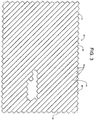
- FIG. 3 is a diagram of a ply 38 suitable for use with the embodiment of the invention illustrated in FIG. 1 .
- the ply 38 includes a ply boundary 40 that defines the edges of the ply 38.
- the ply 38 includes a plurality of courses 42 that are oriented at about 45° relative to the lines of the ply boundary 40.
- the ply 38 further includes a plurality of course interfaces 44 disposed between adjacent courses 42.
- the courses 42 generally include a leading edge 46 and a trailing edge 48. While a 45° is illustrated in FIG. 3 , the courses 42 may be oriented at any suitable angle relative to the ply 38 or substrate 18.
- the courses 42 may be oriented at 0°, 90°, +/- 45° and the like.
- the leading edge 46 and trailing edge 48 of the tape 32 may be positioned to essentially coincide with the ply boundary 40.
- course orientation of 0° and 90° are relatively straightforward, and thus, will not be discussed further herein.
- some portion of one or both of the leading edge 46 and trailing edge 48 may extend beyond the ply boundary 40 as shown in FIG. 3 .
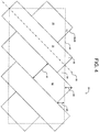
- FIG. 4 is a detailed view of the ply 38 suitable for use with the embodiment of the invention illustrated in FIG. 1 .
- the tape 32 includes a center line 50.
- the tape 32 is positioned upon the ply 38 such that the center line 50, the ply boundary 40, and the leading edge 46 or trailing edge 48 essentially converge or intersect. As such, a portion or a corner of the tape 32 extends to either side of the ply boundary 40 resulting in an overfill 52 and an underfill 54.
- the height 58 is approximately equal to 1.06 inches (2.69cm).
- ⁇ is an angle of incidence (in Radians) between the ply boundary 40 and the leading or trailing edge 46/48 and where n ⁇ 1.
- the leading and trailing edges 46 and 48 may be cut at about 80° to about 100° relative to the center line 50. More particularly, the leading and trailing edges 46 and 48 maybe cut at about 85° to about 95° relative to the center line 50. This variance from 90° is related to the design of the cutting assembly and the speed that the tape 32 is moving as the cut is taking place.
- n being greater than or equal to 1
- the leading and/or trailing edges 46/48 may be disposed any suitable location along the ply boundary 40.
- n may be set to a specific value.
- n i.e., the amount the leading/trailing edges 46/48 overlap the ply boundary 40
- the leading/trailing edges 46/48, ply boundary 40, and center line 50 all essentially converge.
- FIG. 5 is a diagram of a ply placement schema 66 suitable for use with the embodiment of the invention illustrated in FIG. 1 .
- the ply placement schema 66 may be utilized to place a plurality of plies 38a-38n along a transition zone 68.
- the transition zone 68 defines an interface between a first area 70 of the composite item 34 having a first thickness or "skin gauge" and a second area 72 of the composite item 34 having a second skin gauge. Differences in the skin gauges between the first area 70 and the second area 72 are accomplished by altering the number of the plies 38a-38n. That is, to generate a relatively stronger or thicker area on the composite item 34, a relatively greater number of the plies 38a-38n are applied to the substrate 18.
- the plies 38a-38n include respective ply boundaries 40a-n that are spaced across the transition zone 68.
- the plies 38a-38n are staggered as shown in FIG. 5 such that the leading and trailing edges 46/48 and/or the interfaces 44 do not coincide. This crenulation or spacing and staggering eases or smoothes the transition zone 68. In this manner, transitions that are structurally sound, cosmetically appealing, and/or aerodynamically favorable may be generated quickly and efficiently.
- the transition zone 68 includes four +/-45° plies 38a-38d (two +45° and two -45°). For the sake of clarity, 0° and/or 90° plies that may be placed within the transition zone 68 have not been shown. However, typical ply orientation sequence from ply to ply is 45°/90°/-45°/0°. If present, these or other plies placed in between the plies 38a-38d may have respective ply boundaries that fall between the ply boundaries 40a-40d.
- the 0° ply may include a ply boundary disposed about 1/2 of the distance between ply boundary 40a and 40b.
- the 90° ply may include a ply boundary about 1/2 of the distance between ply boundary 40b and 40c.
- the spacing of the ply boundaries 40a-40n is determined by the ply ramp ratio. Typical ramp ratios for aerospace applications include about a 20:1 or the like. However, various embodiments of the invention include any suitable ramp ratio.
- head complexity may be reduced due to the relatively simplified cuts as compared to conventional tape placement devices.
- the simplification of the cuts results in increased head reliability and the ability to utilize multiple heads on a single machine to dramatically increase productivity of composite lay-up machines.
- deliver heads of conventional tape placement machines are not reliable enough to use multiple heads at a single time.
- relatively wider tapes may be utilized.
- the use of relatively wider tapes results in more robust mechanisms, improved head reliability, and increased total width of material capable of being placed by a single machine, resulting in dramatic improvements in machine productivity and reliability.
- leading and trailing ends 46/48 are essentially the same.
- the placement head In conventional ply placement devices, after cutting the trailing end to exactly match the ply boundary, the placement head must move outside the placement area to cut a leading edge profile that matches the beginning of the next course. This process in conventional ply placement devices wastes time and materials. Embodiments of the invention, by virtue of having the leading and trailing edges 46/48 being essentially the same, omit this time consuming operation and do not waste these expensive materials.
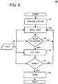
- FIG. 6 is a flow diagram for a method 80 of laying tape courses according to an embodiment of the invention.
- a variety of preparation may occur prior to initiation of the method 60. Examples of pre-initiation preparation may include one or more of: design the composite item 34; generate the file 26 corresponding to the composite item 34; generate the mandrel 20 corresponding to the composite item 34; acquire fabrication materials such as the tape 32; and the like.
- the method 80 is initiated in response to providing a system such as the MHTLM 10.
- the tape 32 is applied to the substrate 20.
- the file 26 is accessed to determine the ply boundaries 40a-40n. Based upon these ply boundaries 40a-40n, the drive apparatus 22 and/or the positioning apparatus 14a-14n are controlled by the control unit 24 to position the placement heads 12a-12n. Thereafter, the placement heads 12a-12n are controlled to place or apply the tape 32.
- step 86 it is determined whether one or more of the placement heads 12a-12n is approaching an end point or ply boundary 40a-40n. For example, the file 26 is accessed and the current position of the placement heads 12a-12n maybe compared to the ply boundaries 40a-40n. In response to it being determined that one or more of the placement heads 12a-12n is approaching an end point or ply boundary 40a-40n, the tape 32 may be cut at step 88. Otherwise, the placement heads 12a-12n may be controlled to continue placing the tape 32 at step 84.
- the tape 32 is cut.
- the control unit 24 may control the placement head 12a-12n to cut the tape 32 in response to the approaching ply boundary 40a-40n.
- the cut is a butt cut. That is, the cut is about perpendicular to the centerline 50 of the tape 32.
- the cut may be timed such that when the tape 32 is placed upon the substrate 18, the cut or trailing edge 48 coincides with the ply boundary 40a-40n.
- step 90 it is determined whether the layup is completed. For example, the file 26 is accessed to determine if there are any further instructions or an end of file ("EOF") identifier is reached. If it is determined that the layup is complete, the composite item 34 may be cured at step 170. If it is determined that the layup is not complete, the tape may be applied at step 84.
- EEF end of file
- the composite item 34 is cured.
- the composite items is placed is a heated and/or pressurized environment to cure the resin in the tape 32.
- the MHTLM 10 may idle or stop until controlled to initiate the method 80 again.
- the method further comprises:
- the method further comprises:
- the method further comprises generating an underfill, wherein an underfill height is about equal to the overfill height.
- the method further comprises: applying the tape at a 90° relative to the ply boundary, wherein the leading edge essentially coincides with the ply boundary.
- transition zone defines an area that begins at a first skin gauge and ends at a second skin gauge, the transition zone includes a first oblique ply boundary that is offset from a second oblique ply boundary, the method comprising:
- the method further comprises: applying a third set of tapes of composite material across a 0° ply boundary between the first set of tapes and the second set of tapes, the 0° ply boundary being disposed between the first oblique ply boundary and the second oblique ply boundary.
- the method further comprises: applying a fourth set of tapes of composite material across a 90° ply boundary between the first set of tapes and the second set of tapes, the 90° ply boundary being disposed between the first oblique ply boundary and the second oblique ply boundary and the 90° ply boundary being offset from the 0° ply boundary, the first oblique ply boundary, and the second oblique ply boundary.
- a computer readable medium on which is embedded computer software comprising a set of instructions for executing a method of applying a course on a layup mold, the method comprising:
- the medium further comprises::
- the medium further comprises:
- the medium further comprises:
- a computer readable medium on which is embedded computer software comprising a set of instructions for executing a method of fabricating a transition zone in a composite item, wherein the transition zone defines an area that begins at a first skin gauge and ends at a second skin gauge, the transition zone includes a first oblique ply boundary that is offset from a second oblique ply boundary, the method comprising:
- the medium further comprises:
- the medium further comprises:
- an apparatus for applying a course on a layup mold comprising:
- the apparatus further comprises:
- the apparatus further comprises:
- the apparatus further comprises:
- the apparatus further comprises:
- an apparatus for fabricating a transition zone in a composite item wherein the transition zone defines an area that begins at a first skin gauge and ends at a second skin gauge, the transition zone includes a first oblique ply boundary that is offset from a second oblique ply boundary, the apparatus comprising:
- the apparatus further comprises:
- the apparatus further comprises:
Landscapes
- Engineering & Computer Science (AREA)
- Chemical & Material Sciences (AREA)
- Composite Materials (AREA)
- Mechanical Engineering (AREA)
- Robotics (AREA)
- Moulding By Coating Moulds (AREA)
Applications Claiming Priority (3)
| Application Number | Priority Date | Filing Date | Title |
|---|---|---|---|
| US11/352,274 US7867352B2 (en) | 2006-02-13 | 2006-02-13 | Composite material placement method and system |
| EP07750758.0A EP1986842B1 (de) | 2006-02-13 | 2007-02-13 | Verfahren zur platzierung eines verbundmaterials |
| PCT/US2007/003939 WO2007095301A2 (en) | 2006-02-13 | 2007-02-13 | Composite material placement method and system |
Related Parent Applications (1)
| Application Number | Title | Priority Date | Filing Date |
|---|---|---|---|
| EP07750758.0A Division EP1986842B1 (de) | 2006-02-13 | 2007-02-13 | Verfahren zur platzierung eines verbundmaterials |
Publications (2)
| Publication Number | Publication Date |
|---|---|
| EP3147110A1 true EP3147110A1 (de) | 2017-03-29 |
| EP3147110B1 EP3147110B1 (de) | 2021-01-06 |
Family
ID=38190627
Family Applications (2)
| Application Number | Title | Priority Date | Filing Date |
|---|---|---|---|
| EP07750758.0A Active EP1986842B1 (de) | 2006-02-13 | 2007-02-13 | Verfahren zur platzierung eines verbundmaterials |
| EP16190548.4A Active EP3147110B1 (de) | 2006-02-13 | 2007-02-13 | Verbundstoffmaterialpositionierungsverfahren |
Family Applications Before (1)
| Application Number | Title | Priority Date | Filing Date |
|---|---|---|---|
| EP07750758.0A Active EP1986842B1 (de) | 2006-02-13 | 2007-02-13 | Verfahren zur platzierung eines verbundmaterials |
Country Status (5)
| Country | Link |
|---|---|
| US (2) | US7867352B2 (de) |
| EP (2) | EP1986842B1 (de) |
| JP (1) | JP5538728B2 (de) |
| ES (1) | ES2609255T3 (de) |
| WO (1) | WO2007095301A2 (de) |
Families Citing this family (29)
| Publication number | Priority date | Publication date | Assignee | Title |
|---|---|---|---|---|
| US8029642B2 (en) | 2007-07-27 | 2011-10-04 | The Boeing Company | Tape removal apparatus and process |
| US8345269B2 (en) | 2007-09-22 | 2013-01-01 | The Boeing Company | Method and apparatus for measuring the width of composite tape |
| US8005559B2 (en) * | 2007-09-26 | 2011-08-23 | The Boeing Company | Optimizing task assignments for multi-head tape laydown |
| US20090084486A1 (en) * | 2007-09-27 | 2009-04-02 | The Boeing Company | Optimized ordering of doubler plies in composite structures |
| US7922856B2 (en) | 2008-01-02 | 2011-04-12 | The Boeing Company | Graphite tape supply and backing paper take-up apparatus |
| US8557074B2 (en) | 2008-02-27 | 2013-10-15 | The Boeing Company | Reduced complexity automatic fiber placement apparatus and method |
| US20090301648A1 (en) * | 2008-06-05 | 2009-12-10 | Merrill Wilson Hogg | Tight constellation composite tape-laying machine |
| US8986482B2 (en) * | 2008-07-08 | 2015-03-24 | The Boeing Company | Method and apparatus for producing composite structures |
| ES2338084B1 (es) * | 2008-10-30 | 2011-03-14 | Airbus Operations, S.L. | Metodo de fabricacion de un panel de geometria compleja en material compuesto preimpregnado. |
| US8308101B2 (en) | 2009-03-09 | 2012-11-13 | The Boeing Company | Simplified fiber tensioning for automated fiber placement machines |
| US8454788B2 (en) | 2009-03-13 | 2013-06-04 | The Boeing Company | Method and apparatus for placing short courses of composite tape |
| US8545657B2 (en) * | 2009-10-30 | 2013-10-01 | Lawrence Livermore National Security, Llc | Methods for tape fabrication of continuous filament composite parts and articles of manufacture thereof |
| DK2536552T3 (da) * | 2010-02-19 | 2014-08-11 | Vestas Wind Sys As | Fiber-anbringelsesapparat med flere hoveder |
| JP5422439B2 (ja) * | 2010-02-26 | 2014-02-19 | 三菱重工業株式会社 | プリプレグ積層ヘッド及びこれを備えたプリプレグ自動積層装置 |
| US10086569B2 (en) * | 2010-05-13 | 2018-10-02 | The Boeing Company | Method of making a composite sandwich structure |
| US8826957B2 (en) * | 2012-08-31 | 2014-09-09 | General Electric Company | Methods and systems for automated ply layup for composites |
| CA2895564C (en) | 2012-12-21 | 2020-03-24 | Short Brothers Plc | Fabric handling apparatus |
| US9481158B2 (en) | 2013-07-11 | 2016-11-01 | The Boeing Company | Short course fiber placement head |
| DE102013112259A1 (de) * | 2013-11-07 | 2015-05-07 | Deutsches Zentrum für Luft- und Raumfahrt e.V. | Verfahren zur Herstellung eines Faservorformlings |
| US20150261888A1 (en) * | 2014-03-14 | 2015-09-17 | Siemens Product Lifecycle Management Software Inc. | Three-dimensional cad method for generating an accurate solid model from a laminated composite part definition |
| US9545759B2 (en) | 2015-01-30 | 2017-01-17 | CGTech | Automated fiber placement with course trajectory compensation |
| US10654228B2 (en) * | 2017-07-28 | 2020-05-19 | The Boeing Company | System and method for forming a part by automated fiber placement |
| US10974465B2 (en) | 2018-06-20 | 2021-04-13 | The Boeing Company | Method and system for generating a layup plan for forming a composite laminate |
| US11999151B2 (en) * | 2019-06-13 | 2024-06-04 | The Board Of Trustees Of The Leland Stanford Junior University | Composite structures containing finite length tapes and methods for manufacturing and using the same |
| US11436390B2 (en) | 2020-06-18 | 2022-09-06 | The Boeing Company | Fiber path planning to reduce in-plane curvature |
| US12240178B1 (en) | 2020-06-18 | 2025-03-04 | The Boeing Company | Layup strategy analysis |
| US11752707B2 (en) | 2021-05-13 | 2023-09-12 | The Board Of Trustees Of The Leland Stanford Junior University | Octogrid constructions and applications utilizing double-double laminate structures |
| US12321149B2 (en) | 2021-05-17 | 2025-06-03 | The Boeing Company | Method for computer analysis of as-programmed surface quality of composite structure |
| US11958244B2 (en) | 2021-12-02 | 2024-04-16 | The Boeing Company | Multi-head automated fiber placement system and method |
Citations (6)
| Publication number | Priority date | Publication date | Assignee | Title |
|---|---|---|---|---|
| GB1314065A (en) * | 1970-04-09 | 1973-04-18 | K Bjuro Mekh I Avtomatiza Tsii | Device for moulding sheets of glass-reinforced plastics |
| DE3331494A1 (de) * | 1983-09-01 | 1985-03-21 | Rudolf 8900 Augsburg Güthler | Mehrband-legemaschine |
| US20040026025A1 (en) * | 2002-06-13 | 2004-02-12 | Kawasaki Jukogyo Kabushiki Kaisha | Automatic prepreg laminating method and apparatus for carrying out the same |
| EP1422048A2 (de) * | 2002-11-22 | 2004-05-26 | The Boeing Company | Verfahren und Vorrichtung zum Formen von Gegenständen aus Verbundmaterialien unter der Verwendung von Materialverteilern und rotationellen Arbeitsflächen |
| WO2005106604A2 (en) * | 2004-04-21 | 2005-11-10 | Ingersoll Machine Tools, Inc. | Controlling high-speed events during automated fiber placement |
| US20050274446A1 (en) * | 2004-06-10 | 2005-12-15 | The Boeing Company | Metal fiber lamination method and system |
Family Cites Families (8)
| Publication number | Priority date | Publication date | Assignee | Title |
|---|---|---|---|---|
| US4867833A (en) * | 1987-09-14 | 1989-09-19 | Carl Strutz & Company, Inc. | Butt-cut label dispenser |
| JPH07110499B2 (ja) * | 1990-09-13 | 1995-11-29 | 東芝機械株式会社 | プリプレグ積層材の製造方法およびその装置 |
| JPH04344225A (ja) * | 1991-05-22 | 1992-11-30 | Mitsubishi Heavy Ind Ltd | 複合材自動積層装置 |
| US5562788A (en) * | 1994-09-20 | 1996-10-08 | The Boeing Company | Composite material laser flaw detection |
| JP3649706B2 (ja) * | 2002-06-20 | 2005-05-18 | 川崎重工業株式会社 | プリプレグ自動積層方法及びその装置 |
| US7282107B2 (en) * | 2003-08-22 | 2007-10-16 | The Boeing Company | Multiple head automated composite laminating machine for the fabrication of large barrel section components |
| US7341086B2 (en) * | 2004-10-29 | 2008-03-11 | The Boeing Company | Automated fabric layup system and method |
| US20060118244A1 (en) * | 2004-12-02 | 2006-06-08 | The Boeing Company | Device for laying tape materials for aerospace applications |
-
2006
- 2006-02-13 US US11/352,274 patent/US7867352B2/en active Active
-
2007
- 2007-02-13 WO PCT/US2007/003939 patent/WO2007095301A2/en not_active Ceased
- 2007-02-13 EP EP07750758.0A patent/EP1986842B1/de active Active
- 2007-02-13 EP EP16190548.4A patent/EP3147110B1/de active Active
- 2007-02-13 JP JP2008555328A patent/JP5538728B2/ja active Active
- 2007-02-13 ES ES07750758.0T patent/ES2609255T3/es active Active
-
2010
- 2010-12-06 US US12/961,066 patent/US9114575B2/en active Active
Patent Citations (6)
| Publication number | Priority date | Publication date | Assignee | Title |
|---|---|---|---|---|
| GB1314065A (en) * | 1970-04-09 | 1973-04-18 | K Bjuro Mekh I Avtomatiza Tsii | Device for moulding sheets of glass-reinforced plastics |
| DE3331494A1 (de) * | 1983-09-01 | 1985-03-21 | Rudolf 8900 Augsburg Güthler | Mehrband-legemaschine |
| US20040026025A1 (en) * | 2002-06-13 | 2004-02-12 | Kawasaki Jukogyo Kabushiki Kaisha | Automatic prepreg laminating method and apparatus for carrying out the same |
| EP1422048A2 (de) * | 2002-11-22 | 2004-05-26 | The Boeing Company | Verfahren und Vorrichtung zum Formen von Gegenständen aus Verbundmaterialien unter der Verwendung von Materialverteilern und rotationellen Arbeitsflächen |
| WO2005106604A2 (en) * | 2004-04-21 | 2005-11-10 | Ingersoll Machine Tools, Inc. | Controlling high-speed events during automated fiber placement |
| US20050274446A1 (en) * | 2004-06-10 | 2005-12-15 | The Boeing Company | Metal fiber lamination method and system |
Also Published As
| Publication number | Publication date |
|---|---|
| US9114575B2 (en) | 2015-08-25 |
| US7867352B2 (en) | 2011-01-11 |
| EP1986842A2 (de) | 2008-11-05 |
| JP5538728B2 (ja) | 2014-07-02 |
| WO2007095301A3 (en) | 2007-10-04 |
| EP3147110B1 (de) | 2021-01-06 |
| ES2609255T3 (es) | 2017-04-19 |
| WO2007095301A2 (en) | 2007-08-23 |
| US20070187024A1 (en) | 2007-08-16 |
| US20110073238A1 (en) | 2011-03-31 |
| EP1986842B1 (de) | 2016-09-28 |
| JP2009526678A (ja) | 2009-07-23 |
Similar Documents
| Publication | Publication Date | Title |
|---|---|---|
| EP3147110B1 (de) | Verbundstoffmaterialpositionierungsverfahren | |
| EP2540480B1 (de) | Automatische Harz- und Faserablagerung zur Harzinfusion | |
| US8591685B2 (en) | Method and apparatus for producing composite fillers | |
| EP2403706B1 (de) | Verfahren zur herstellung von konturierten verbundstrukturen | |
| EP2285670B1 (de) | Verfahren zur herstellung von konturierten verbundstrukturen | |
| EP2386483B1 (de) | Gebogene Verbundstoffrahmen und Verfahren zu ihrer Herstellung | |
| US9387657B2 (en) | Method of fabricating a curved composite structure using composite prepreg tape | |
| EP2130666A2 (de) | Festkonstellations-Verbundwerkstoffbandauflegemaschine | |
| EP3599083B1 (de) | Kontinuierliche herstellung für verbundwerkstoffvorformen | |
| WO2014107241A1 (en) | Method of fabricating a curved composite structure using composite prepreg tape | |
| EP3868548B1 (de) | Verfahren zur herstellung von soliden laminatstringern auf einer verbundplatte | |
| EP4431268B1 (de) | Verbundteile und verfahren zur herstellung | |
| HK1119633B (en) | Composite material placement method |
Legal Events
| Date | Code | Title | Description |
|---|---|---|---|
| PUAI | Public reference made under article 153(3) epc to a published international application that has entered the european phase |
Free format text: ORIGINAL CODE: 0009012 |
|
| STAA | Information on the status of an ep patent application or granted ep patent |
Free format text: STATUS: REQUEST FOR EXAMINATION WAS MADE |
|
| 17P | Request for examination filed |
Effective date: 20160926 |
|
| AC | Divisional application: reference to earlier application |
Ref document number: 1986842 Country of ref document: EP Kind code of ref document: P |
|
| AK | Designated contracting states |
Kind code of ref document: A1 Designated state(s): AT BE BG CH CY CZ DE DK EE ES FI FR GB GR HU IE IS IT LI LT LU LV MC NL PL PT RO SE SI SK TR |
|
| R17P | Request for examination filed (corrected) |
Effective date: 20170510 |
|
| RBV | Designated contracting states (corrected) |
Designated state(s): AT BE BG CH CY CZ DE DK EE ES FI FR GB GR HU IE IS IT LI LT LU LV MC NL PL PT RO SE SI SK TR |
|
| R17P | Request for examination filed (corrected) |
Effective date: 20160926 |
|
| GRAP | Despatch of communication of intention to grant a patent |
Free format text: ORIGINAL CODE: EPIDOSNIGR1 |
|
| STAA | Information on the status of an ep patent application or granted ep patent |
Free format text: STATUS: GRANT OF PATENT IS INTENDED |
|
| GRAJ | Information related to disapproval of communication of intention to grant by the applicant or resumption of examination proceedings by the epo deleted |
Free format text: ORIGINAL CODE: EPIDOSDIGR1 |
|
| STAA | Information on the status of an ep patent application or granted ep patent |
Free format text: STATUS: REQUEST FOR EXAMINATION WAS MADE |
|
| GRAP | Despatch of communication of intention to grant a patent |
Free format text: ORIGINAL CODE: EPIDOSNIGR1 |
|
| GRAJ | Information related to disapproval of communication of intention to grant by the applicant or resumption of examination proceedings by the epo deleted |
Free format text: ORIGINAL CODE: EPIDOSDIGR1 |
|
| GRAP | Despatch of communication of intention to grant a patent |
Free format text: ORIGINAL CODE: EPIDOSNIGR1 |
|
| STAA | Information on the status of an ep patent application or granted ep patent |
Free format text: STATUS: GRANT OF PATENT IS INTENDED |
|
| INTG | Intention to grant announced |
Effective date: 20200717 |
|
| INTG | Intention to grant announced |
Effective date: 20200730 |
|
| INTG | Intention to grant announced |
Effective date: 20200804 |
|
| GRAS | Grant fee paid |
Free format text: ORIGINAL CODE: EPIDOSNIGR3 |
|
| GRAA | (expected) grant |
Free format text: ORIGINAL CODE: 0009210 |
|
| STAA | Information on the status of an ep patent application or granted ep patent |
Free format text: STATUS: THE PATENT HAS BEEN GRANTED |
|
| AC | Divisional application: reference to earlier application |
Ref document number: 1986842 Country of ref document: EP Kind code of ref document: P |
|
| AK | Designated contracting states |
Kind code of ref document: B1 Designated state(s): AT BE BG CH CY CZ DE DK EE ES FI FR GB GR HU IE IS IT LI LT LU LV MC NL PL PT RO SE SI SK TR |
|
| REG | Reference to a national code |
Ref country code: GB Ref legal event code: FG4D |
|
| REG | Reference to a national code |
Ref country code: AT Ref legal event code: REF Ref document number: 1351904 Country of ref document: AT Kind code of ref document: T Effective date: 20210115 Ref country code: CH Ref legal event code: EP |
|
| REG | Reference to a national code |
Ref country code: DE Ref legal event code: R096 Ref document number: 602007060895 Country of ref document: DE |
|
| REG | Reference to a national code |
Ref country code: IE Ref legal event code: FG4D |
|
| REG | Reference to a national code |
Ref country code: NL Ref legal event code: MP Effective date: 20210106 |
|
| REG | Reference to a national code |
Ref country code: AT Ref legal event code: MK05 Ref document number: 1351904 Country of ref document: AT Kind code of ref document: T Effective date: 20210106 |
|
| REG | Reference to a national code |
Ref country code: LT Ref legal event code: MG9D |
|
| PG25 | Lapsed in a contracting state [announced via postgrant information from national office to epo] |
Ref country code: PT Free format text: LAPSE BECAUSE OF FAILURE TO SUBMIT A TRANSLATION OF THE DESCRIPTION OR TO PAY THE FEE WITHIN THE PRESCRIBED TIME-LIMIT Effective date: 20210506 Ref country code: FI Free format text: LAPSE BECAUSE OF FAILURE TO SUBMIT A TRANSLATION OF THE DESCRIPTION OR TO PAY THE FEE WITHIN THE PRESCRIBED TIME-LIMIT Effective date: 20210106 Ref country code: GR Free format text: LAPSE BECAUSE OF FAILURE TO SUBMIT A TRANSLATION OF THE DESCRIPTION OR TO PAY THE FEE WITHIN THE PRESCRIBED TIME-LIMIT Effective date: 20210407 Ref country code: LT Free format text: LAPSE BECAUSE OF FAILURE TO SUBMIT A TRANSLATION OF THE DESCRIPTION OR TO PAY THE FEE WITHIN THE PRESCRIBED TIME-LIMIT Effective date: 20210106 Ref country code: BG Free format text: LAPSE BECAUSE OF FAILURE TO SUBMIT A TRANSLATION OF THE DESCRIPTION OR TO PAY THE FEE WITHIN THE PRESCRIBED TIME-LIMIT Effective date: 20210406 Ref country code: NL Free format text: LAPSE BECAUSE OF FAILURE TO SUBMIT A TRANSLATION OF THE DESCRIPTION OR TO PAY THE FEE WITHIN THE PRESCRIBED TIME-LIMIT Effective date: 20210106 |
|
| PG25 | Lapsed in a contracting state [announced via postgrant information from national office to epo] |
Ref country code: SE Free format text: LAPSE BECAUSE OF FAILURE TO SUBMIT A TRANSLATION OF THE DESCRIPTION OR TO PAY THE FEE WITHIN THE PRESCRIBED TIME-LIMIT Effective date: 20210106 Ref country code: AT Free format text: LAPSE BECAUSE OF FAILURE TO SUBMIT A TRANSLATION OF THE DESCRIPTION OR TO PAY THE FEE WITHIN THE PRESCRIBED TIME-LIMIT Effective date: 20210106 Ref country code: LV Free format text: LAPSE BECAUSE OF FAILURE TO SUBMIT A TRANSLATION OF THE DESCRIPTION OR TO PAY THE FEE WITHIN THE PRESCRIBED TIME-LIMIT Effective date: 20210106 Ref country code: PL Free format text: LAPSE BECAUSE OF FAILURE TO SUBMIT A TRANSLATION OF THE DESCRIPTION OR TO PAY THE FEE WITHIN THE PRESCRIBED TIME-LIMIT Effective date: 20210106 |
|
| PG25 | Lapsed in a contracting state [announced via postgrant information from national office to epo] |
Ref country code: IS Free format text: LAPSE BECAUSE OF FAILURE TO SUBMIT A TRANSLATION OF THE DESCRIPTION OR TO PAY THE FEE WITHIN THE PRESCRIBED TIME-LIMIT Effective date: 20210506 |
|
| REG | Reference to a national code |
Ref country code: DE Ref legal event code: R097 Ref document number: 602007060895 Country of ref document: DE |
|
| REG | Reference to a national code |
Ref country code: BE Ref legal event code: MM Effective date: 20210228 |
|
| PG25 | Lapsed in a contracting state [announced via postgrant information from national office to epo] |
Ref country code: LI Free format text: LAPSE BECAUSE OF NON-PAYMENT OF DUE FEES Effective date: 20210228 Ref country code: LU Free format text: LAPSE BECAUSE OF NON-PAYMENT OF DUE FEES Effective date: 20210213 Ref country code: MC Free format text: LAPSE BECAUSE OF FAILURE TO SUBMIT A TRANSLATION OF THE DESCRIPTION OR TO PAY THE FEE WITHIN THE PRESCRIBED TIME-LIMIT Effective date: 20210106 Ref country code: CZ Free format text: LAPSE BECAUSE OF FAILURE TO SUBMIT A TRANSLATION OF THE DESCRIPTION OR TO PAY THE FEE WITHIN THE PRESCRIBED TIME-LIMIT Effective date: 20210106 Ref country code: EE Free format text: LAPSE BECAUSE OF FAILURE TO SUBMIT A TRANSLATION OF THE DESCRIPTION OR TO PAY THE FEE WITHIN THE PRESCRIBED TIME-LIMIT Effective date: 20210106 Ref country code: CH Free format text: LAPSE BECAUSE OF NON-PAYMENT OF DUE FEES Effective date: 20210228 |
|
| PLBE | No opposition filed within time limit |
Free format text: ORIGINAL CODE: 0009261 |
|
| STAA | Information on the status of an ep patent application or granted ep patent |
Free format text: STATUS: NO OPPOSITION FILED WITHIN TIME LIMIT |
|
| PG25 | Lapsed in a contracting state [announced via postgrant information from national office to epo] |
Ref country code: ES Free format text: LAPSE BECAUSE OF FAILURE TO SUBMIT A TRANSLATION OF THE DESCRIPTION OR TO PAY THE FEE WITHIN THE PRESCRIBED TIME-LIMIT Effective date: 20210106 Ref country code: DK Free format text: LAPSE BECAUSE OF FAILURE TO SUBMIT A TRANSLATION OF THE DESCRIPTION OR TO PAY THE FEE WITHIN THE PRESCRIBED TIME-LIMIT Effective date: 20210106 Ref country code: SK Free format text: LAPSE BECAUSE OF FAILURE TO SUBMIT A TRANSLATION OF THE DESCRIPTION OR TO PAY THE FEE WITHIN THE PRESCRIBED TIME-LIMIT Effective date: 20210106 Ref country code: RO Free format text: LAPSE BECAUSE OF FAILURE TO SUBMIT A TRANSLATION OF THE DESCRIPTION OR TO PAY THE FEE WITHIN THE PRESCRIBED TIME-LIMIT Effective date: 20210106 |
|
| 26N | No opposition filed |
Effective date: 20211007 |
|
| PG25 | Lapsed in a contracting state [announced via postgrant information from national office to epo] |
Ref country code: IE Free format text: LAPSE BECAUSE OF NON-PAYMENT OF DUE FEES Effective date: 20210213 |
|
| PG25 | Lapsed in a contracting state [announced via postgrant information from national office to epo] |
Ref country code: SI Free format text: LAPSE BECAUSE OF FAILURE TO SUBMIT A TRANSLATION OF THE DESCRIPTION OR TO PAY THE FEE WITHIN THE PRESCRIBED TIME-LIMIT Effective date: 20210106 |
|
| PG25 | Lapsed in a contracting state [announced via postgrant information from national office to epo] |
Ref country code: IT Free format text: LAPSE BECAUSE OF FAILURE TO SUBMIT A TRANSLATION OF THE DESCRIPTION OR TO PAY THE FEE WITHIN THE PRESCRIBED TIME-LIMIT Effective date: 20210106 |
|
| PG25 | Lapsed in a contracting state [announced via postgrant information from national office to epo] |
Ref country code: IS Free format text: LAPSE BECAUSE OF FAILURE TO SUBMIT A TRANSLATION OF THE DESCRIPTION OR TO PAY THE FEE WITHIN THE PRESCRIBED TIME-LIMIT Effective date: 20210506 |
|
| PG25 | Lapsed in a contracting state [announced via postgrant information from national office to epo] |
Ref country code: BE Free format text: LAPSE BECAUSE OF NON-PAYMENT OF DUE FEES Effective date: 20210228 |
|
| PG25 | Lapsed in a contracting state [announced via postgrant information from national office to epo] |
Ref country code: HU Free format text: LAPSE BECAUSE OF FAILURE TO SUBMIT A TRANSLATION OF THE DESCRIPTION OR TO PAY THE FEE WITHIN THE PRESCRIBED TIME-LIMIT; INVALID AB INITIO Effective date: 20070213 Ref country code: CY Free format text: LAPSE BECAUSE OF FAILURE TO SUBMIT A TRANSLATION OF THE DESCRIPTION OR TO PAY THE FEE WITHIN THE PRESCRIBED TIME-LIMIT Effective date: 20210106 |
|
| P01 | Opt-out of the competence of the unified patent court (upc) registered |
Effective date: 20230516 |
|
| PG25 | Lapsed in a contracting state [announced via postgrant information from national office to epo] |
Ref country code: TR Free format text: LAPSE BECAUSE OF FAILURE TO SUBMIT A TRANSLATION OF THE DESCRIPTION OR TO PAY THE FEE WITHIN THE PRESCRIBED TIME-LIMIT Effective date: 20210106 |
|
| PGFP | Annual fee paid to national office [announced via postgrant information from national office to epo] |
Ref country code: GB Payment date: 20260227 Year of fee payment: 20 |
|
| PGFP | Annual fee paid to national office [announced via postgrant information from national office to epo] |
Ref country code: DE Payment date: 20260227 Year of fee payment: 20 |
|
| PGFP | Annual fee paid to national office [announced via postgrant information from national office to epo] |
Ref country code: FR Payment date: 20260225 Year of fee payment: 20 |