EP3147113A1 - Agencement pour enveloppe destiné au rechapage de pneumatique - Google Patents
Agencement pour enveloppe destiné au rechapage de pneumatique Download PDFInfo
- Publication number
- EP3147113A1 EP3147113A1 EP15796291.1A EP15796291A EP3147113A1 EP 3147113 A1 EP3147113 A1 EP 3147113A1 EP 15796291 A EP15796291 A EP 15796291A EP 3147113 A1 EP3147113 A1 EP 3147113A1
- Authority
- EP
- European Patent Office
- Prior art keywords
- envelope
- flap
- tread
- section
- thickness
- Prior art date
- Legal status (The legal status is an assumption and is not a legal conclusion. Google has not performed a legal analysis and makes no representation as to the accuracy of the status listed.)
- Withdrawn
Links
Images




Classifications
-
- B—PERFORMING OPERATIONS; TRANSPORTING
- B29—WORKING OF PLASTICS; WORKING OF SUBSTANCES IN A PLASTIC STATE IN GENERAL
- B29D—PRODUCING PARTICULAR ARTICLES FROM PLASTICS OR FROM SUBSTANCES IN A PLASTIC STATE
- B29D30/00—Producing pneumatic or solid tyres or parts thereof
- B29D30/06—Pneumatic tyres or parts thereof (e.g. produced by casting, moulding, compression moulding, injection moulding, centrifugal casting)
- B29D30/52—Unvulcanised treads, e.g. on used tyres; Retreading
- B29D30/54—Retreading
- B29D30/542—Retreading using envelopes or membranes provided with sealings for curing
-
- B—PERFORMING OPERATIONS; TRANSPORTING
- B29—WORKING OF PLASTICS; WORKING OF SUBSTANCES IN A PLASTIC STATE IN GENERAL
- B29D—PRODUCING PARTICULAR ARTICLES FROM PLASTICS OR FROM SUBSTANCES IN A PLASTIC STATE
- B29D30/00—Producing pneumatic or solid tyres or parts thereof
- B29D30/06—Pneumatic tyres or parts thereof (e.g. produced by casting, moulding, compression moulding, injection moulding, centrifugal casting)
- B29D30/0601—Vulcanising tyres; Vulcanising presses for tyres
- B29D30/0654—Flexible cores therefor, e.g. bladders, bags, membranes, diaphragms
-
- B—PERFORMING OPERATIONS; TRANSPORTING
- B29—WORKING OF PLASTICS; WORKING OF SUBSTANCES IN A PLASTIC STATE IN GENERAL
- B29D—PRODUCING PARTICULAR ARTICLES FROM PLASTICS OR FROM SUBSTANCES IN A PLASTIC STATE
- B29D30/00—Producing pneumatic or solid tyres or parts thereof
- B29D30/06—Pneumatic tyres or parts thereof (e.g. produced by casting, moulding, compression moulding, injection moulding, centrifugal casting)
- B29D30/52—Unvulcanised treads, e.g. on used tyres; Retreading
- B29D30/54—Retreading
-
- B—PERFORMING OPERATIONS; TRANSPORTING
- B29—WORKING OF PLASTICS; WORKING OF SUBSTANCES IN A PLASTIC STATE IN GENERAL
- B29D—PRODUCING PARTICULAR ARTICLES FROM PLASTICS OR FROM SUBSTANCES IN A PLASTIC STATE
- B29D30/00—Producing pneumatic or solid tyres or parts thereof
- B29D30/06—Pneumatic tyres or parts thereof (e.g. produced by casting, moulding, compression moulding, injection moulding, centrifugal casting)
- B29D30/0601—Vulcanising tyres; Vulcanising presses for tyres
- B29D30/0654—Flexible cores therefor, e.g. bladders, bags, membranes, diaphragms
- B29D2030/0659—Details or accessories for the flexible cores not otherwise provided for
Definitions
- the present utility model is related to the technical field of tire retreading for the cold retreading process and, more particularly, to a configuration applied to envelope for tire retreading for the cold retreading process.
- the tire retreading consists of the process of integrating a new tread pattern on a tire carcass which had its original tread worn or damaged, thus re-establishing the conditions of use of the tire.
- a new pre-shaped tread with a particular pattern of grooves is positioned on a tire carcass ready to be retreaded.
- the set is taken to a pressurized and heated environment, such as an autoclave, for a given time.
- the tread is integrated to the tire carcass.
- the process of cold retreading is often used in the retreading of tires for heavy vehicles, especially trucks and buses.
- a conventional envelope consists of a membrane in a single body, made of flexible material, and having a shape suitable to externally cover the flanks of the carcass and the outer surface of the tread. Still, the envelope is provided with an air valve.
- the coating process of the set of carcass and tread by the envelope also known as enveloping, is extremely difficult, since the conventional envelope must be drawn from its central hole until the set of carcass and tread can be introduced inside the envelope. Normally, this enveloping process is accomplished with the aid of equipment called an enveloper, which comprises a set of arms employed to stretch the conventional envelope.
- an inner envelope installed inside the carcass can be used, so that the said inner envelope covers all internal surfaces of the carcass, outlining the carcass bead regions and advancing over part of the external surface of each flank of the carcass, where a sealing with each end of the conventional envelope is provided.
- a rim to close the conventional envelope with the carcass can be used. In this case, the ends of the envelope, in the vicinity of the carcass bead, are pressed against the outer surface of the rim, forming sealed joints.
- an air pump connected to the air valve of the conventional envelope is used, to form a vacuum in the internal environment of the same. From this moment, the set is ready to be taken to the pressurized and heated environment, such as an autoclave.
- the Patent BRPI8406324-6 proposes an envelope consisting of two parts, the first part with a shape capable of externally covering a first flank of the carcass and half of the tread, and the second part with a shape able to externally cover the second flank of the carcass and the other half of the tread and being that in the central region of the top of the tread a region from the end of the first part is facing out and a region from the end of the second part is folded out, the said end regions being placed face to face and retained by tightening a pair of retaining rings, in order to form a seal joint between the parts which aid the vacuum forming internally to the envelope.
- Patent BRMU7901957-9 proposes another envelope configuration consisting of two parts, given that for the sealing between the parts in the center of the top of the tread, the first part has an end region covered by a region of the end of the second part, forming a gasket by overlap.
- this configuration eliminates the use of a pair of retaining rings, the seal configuration between the parts of the envelope is not satisfactory, since air leaks occur into the envelope.
- the carcass and tread set is taken to a pressurized and heated environment, such as an autoclave, for a given time.
- a pressurized and heated environment such as an autoclave
- the envelope is pressed against the tread due to the pressure existing outside the envelope so that the tread and carcass are forced against each other.
- heat is applied in order to vulcanize the tread on the carcass.
- the present utility model aims to propose a configuration applied to an envelope for retreading tires that would suppress or mitigate the limitations presented in the state of the art. More particularly, the present utility model aims to propose a configuration applied to envelope which enables the enveloping of the carcass and tread set to be accomplished without the need for large stretches of the envelope and without the need to use enveloping equipment.
- the present utility model further aims to propose an envelope with improved useful life, with low complexity and low-cost for manufacturing.
- the present utility model aims to propose an envelope that provides an excellent seal for the set of carcass and tread, to prevent any air from entering internally to the envelope after enveloping and vacuum forming.
- the present envelope for tire retreading comprises three parts; wherein the first part comprises a side wall, from which extends a flap, the said sidewall containing a shape able to cover at least a part of the outer portion of a first flank of the carcass and a first shoulder of the tread, and the said flap having a shape capable of covering a first portion of the top of the tread, wherein the free end of the said flap has at least a differentiated cross-section with a thickness greater than the thickness of the said flap; wherein the second part comprises a side wall, from which extends a flap, the said side wall having a shape able to cover at least part of the outer portion of a second flank of the carcass and a second shoulder of the tread, and the said flap having a shape able to cover a second portion of top of the tread, other than the first portion covered by the flap of the first part, and the free end of the flap of the second part has at least a differentiated cross-section with a thickness greater than the thickness of the flap
- the third part with the shape of an elastic ring remains pressed against the flap of the first part and against the flap of the second part, creating a seal between the parts.
- the presence of the differentiated cross section on the free end of the flap of the first part increases the sealing effect between the said first part and the third part
- the presence of the differentiated cross section on the free end of the flap of the second part increases the sealing effect between the said second part and the third part, caused by the suction of air through the air valve.
- an envelope which provides an excellent seal for the carcass and tread set is obtained, to prevent any air from entering internally to the envelope after enveloping and vacuum forming.
- a tire casing (12) ready to be retreaded is covered by a new pre-shaped tread (14) having a top (145) with a particular pattern of grooves (141).
- the casing (12) consists of a pair of flanks (121, 122), each flank (121, 122) from a region called bead (124) until they are joined together by a central portion (123).
- the tread (14) is delimited by a pair of shoulders (142, 144) and is positioned on the outer surface of the central portion (123) of the casing (12), where the shoulders (142, 144) define the lateral ends of the tread (14) positioned according to its related flank (121, 122) of the casing (12).
- a suitable means is used, such as a connection rubber or a orbicushion rubber, both known to be state of the art.
- the set of casing (12) and tread (14) should be taken to a pressurized and heated environment, such as an autoclave, for a given time.
- a pressurized and heated environment such as an autoclave
- the new tread (14) is integrated in the tire casing (12), re-establishing the conditions of use for the tire.
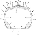
- the present utility model proposes a configuration of an envelope (20) for tire retreading, the said envelope (20) being comprised of three parts (22, 24, 26); wherein the first part (22) comprises a side wall (222), from which extends a flap (224), the said sidewall (222) containing a shape able to cover at least a part of the outer portion of a first flank (121) of the casing (12) and a first shoulder (142) of the tread (14), and the said flap (224) having a shape capable of covering a first portion of the top (145) of the tread (14), wherein the free end of the said flap (224) has at least a differentiated cross-section (224b) with a thickness greater than the thickness of the said flap (224); wherein the second part (24) comprises a side wall (242), from which extends a flap (244), the said side wall (242) having a shape able to cover at least part of the outer portion of a second flank (122) of the casing (12) and a second shoulder (144)
- the third part (26) in the shape of an elastic ring remains pressed against the flap (224) of the first part (22) and against the flap (244) of the second part (24), creating a seal between the parts (22, 24, 26).
- the presence of the differentiated cross-section (224b) on the free end of the flap (224) of the first part (22) increases the sealing effect between said first part (22) and the third part (26)
- the presence of the differentiated cross-section (244b) on the free end of the flap (244) of the second part (24) increases the sealing effect between said second part (24) and the third part (26), created by the suction of air through the air valve (28).
- an envelope (20) which provides an excellent seal in relation to the set of casing (12) and tread (14) is obtained, in order to prevent any air from entering internally to the envelope (20) after enveloping and vacuum forming.
- the flap (224) of the first part (22) extends until a previous position to the median plane (M) of the tread (14) and, preferably, the flap (244) of the second part (24) extends until a previous position to the median plan (M) of the tread (14).
- the first part (22) and the second part (24) are manufactured in a single die, so they are identical to each other. Thus, advantageously, in case of damage in one of those parts (22, 24), only the damaged part is replaced.
- the envelope (20) must also be closed next to the casing (12) for the formation of the vacuum internally to the envelope (20).
- an inner envelope (30) installed inside the casing (12) can be used, so that the inner envelope (30) covers all internal surfaces of the casing (12), outlining the regions of the bead (124) of the casing (12) and advancing over part of the external surface of each flank (121, 122) of the casing (12).
- a region of the end of the sidewall (222, 242) of the respective part (22, 24) is positioned over a respective region of the end of the inner envelope (30), in order to form a seal joint when forming the vacuum.
- a ring (40) for closing the envelope (20) next to the casing (12) can be used, as it can be seen in Figures 4 to 6 .
- both the side wall (222) of the first part (22) and the side wall (242) of the second part (24) move close to the bead (124) from their flank (121, 122) of the casing (12) and remain pressed against the outer surface of the rim (40), forming sealed joints.
- the side wall (222) of the first part (22) advances and gets around the bead region (124) of the first flank (121) of the casing (12), covers the entire inner surface of the casing (12), gets around the bead region (124) of the second flank (122) and advances over part of the outer surface of the second flank (122) of the casing (12).
- a region of the end of the sidewall (242) of the second part (24) is positioned over a region of the end of the first part (22), in order to form a sealing joint when the vacuum is formed.
- the set of casing (12) and tread (14) is ready to be taken to the pressurized and heated environment, such as an autoclave.
- the first part (22) has a uniform thickness, with the exception of its differentiated cross-section (224b), and the second part (24) having a uniform thickness, with the exception of its differentiated cross-section (244b), and the thickness of the first part (22) identical to the thickness of the second part (24).
- the thickness of the first part (22) and of the second part (24) assumes a value of 2 to 3.5 mm.
- the thickness of the first part (22) and the second part (24) is greater from a transition point (T) until a point immediately preceding the differentiated cross-section (224b, 244b) present in the flap (224, 244), where each transition point (T) is located on the sidewall (222, 242) of the respective part (22, 24) in a position next to the respective shoulder (142, 144) of the tread (14).
- each transition point (T) is located in a position above half of the height of its flank (121, 122) of the casing (12) and prior to the top (145) of the tread (14).
- first part (22) and the second part (24) of the envelope (20) present variable thickness is preferred in relation to the configuration where the first part (22) and the second part (24) of the envelope (20) have uniform thickness, since the fact that a portion of the respective sidewall (222, 242) after the transition point (T) and the corresponding flap (224, 244) of the first part (22) and of the second part (24) have a greater thickness allows the said parts (22, 24) of the envelope (20) to assume a more structured shape and closest to the shape of the set of casing (12) and (14) tread.
- the handling and installation of the first part (22) and of the second part (24) on the set of casing (12) and tread (14) become easier.
- the fact that the respective flap (224, 244) of the first part (22) and of the second part (24) have a greater thickness prevents the said flap (224, 244) from being stretched into the grooves (141) of the tread (14), whether due to vacuum formed internally to the envelope (20), or due to external pressure applied to the envelope (20) during the autoclave process.
- deformations in the flaps (224, 244) of the said parts (22, 24) of the envelope (20) are avoided, and, consequently, fatigue stresses that would be caused by this repeated deformation over several cycles of using the same envelope (20) are avoided, contributing to an increase of its useful life.
- the fact that a portion of the sidewall (222, 242) prior to the transition point (T) is of a lesser thickness advantageously, represents a savings of material in the production of the first part (22) and of the second part (24) of the envelope (20).
- the thickness of the portion of the side wall (222, 242) prior to the transition point (T) assumes a value of 2 to 3.5 mm.
- the thickness of the side wall portion (222, 242) after the transition point (T) and the thickness of the flap (224, 244) until a point immediately preceding the differentiated cross-section (224b, 244b) assume a value greater than the value of the thickness of the side wall portion (224, 244) prior to the transition point (T).
- this higher value is no more than 6 mm.
- the thickness of the sidewall (224, 244), from the transition point (T), and the thickness of the flap (224, 244) will have a value greater than 3 mm.
- This increase in thickness can be achieved gradually, as depicted in Figures 3 and 6 , for example, starting with 3.1 mm at a point immediately after the transition point (T) and ending with 5 mm at one point immediately preceding the differentiated cross-section (224b, 244b).
- this increase in thickness can be achieved abruptly, according to a non-represented configuration, for example, from 3 mm to 5 mm at a point immediately after the transition point (T) and remaining uniform at 5 mm up to the point immediately preceding the differentiated cross-section (224b, 244b).
- each differentiated cross-section (224b, 244b) present in the free end of the flap (224, 244) of the first part (22) and of second part (24) has a rectangular shape.
- each differentiated cross-section (224b, 244b) can have another shape, such as, for example, a circular shape.
- the thickness of each differentiated cross-section (224b, 244b) assumes a value greater than the thickness of the flap (224, 244), at one point immediately preceding the said differentiated cross-section (224b, 244b), preferably between 8 and 12 mm.
- the thickness of the third part (26) in the shape of an elastic ring assumes a value between 3 and 5 mm.
Landscapes
- Engineering & Computer Science (AREA)
- Mechanical Engineering (AREA)
- Tyre Moulding (AREA)
- Sheet Holders (AREA)
- Packaging Of Annular Or Rod-Shaped Articles, Wearing Apparel, Cassettes, Or The Like (AREA)
- Moulds For Moulding Plastics Or The Like (AREA)
- Tires In General (AREA)
- Heating, Cooling, Or Curing Plastics Or The Like In General (AREA)
Applications Claiming Priority (2)
| Application Number | Priority Date | Filing Date | Title |
|---|---|---|---|
| BR202014012293U BR202014012293U2 (pt) | 2014-05-21 | 2014-05-21 | configuração aplicada em envelope para recauchutagem de pneumático |
| PCT/BR2015/000080 WO2015176148A1 (fr) | 2014-05-21 | 2015-05-21 | Agencement pour enveloppe destiné au rechapage de pneumatique |
Publications (2)
| Publication Number | Publication Date |
|---|---|
| EP3147113A1 true EP3147113A1 (fr) | 2017-03-29 |
| EP3147113A4 EP3147113A4 (fr) | 2018-02-28 |
Family
ID=54553125
Family Applications (1)
| Application Number | Title | Priority Date | Filing Date |
|---|---|---|---|
| EP15796291.1A Withdrawn EP3147113A4 (fr) | 2014-05-21 | 2015-05-21 | Agencement pour enveloppe destiné au rechapage de pneumatique |
Country Status (6)
| Country | Link |
|---|---|
| US (1) | US20170165935A1 (fr) |
| EP (1) | EP3147113A4 (fr) |
| AR (1) | AR100546A1 (fr) |
| BR (1) | BR202014012293U2 (fr) |
| MX (1) | MX2016015327A (fr) |
| WO (1) | WO2015176148A1 (fr) |
Families Citing this family (1)
| Publication number | Priority date | Publication date | Assignee | Title |
|---|---|---|---|---|
| WO2016201533A1 (fr) * | 2015-06-19 | 2016-12-22 | Borrachas Vipal S.A. | Agencement pour enveloppe destiné au rechapage de pneumatique |
Family Cites Families (12)
| Publication number | Priority date | Publication date | Assignee | Title |
|---|---|---|---|---|
| FR1411387A (fr) * | 1964-08-19 | 1965-09-17 | Procédé de vulcanisation | |
| US3884740A (en) * | 1973-09-20 | 1975-05-20 | Wilhelm Schelkmann | Method of retreading tires |
| DE2145574C3 (de) * | 1971-09-11 | 1978-12-21 | Vakuum Vulk Holdings Ltd., Nassau | Verfahren und Bindekautschukschicht zum Erneuern des Laufstreifens eines abgefahrenen Luft- oder Vollgummireifens |
| CH554742A (de) * | 1972-04-11 | 1974-10-15 | Schelkmann Wilhelm | Verfahren zum runderneuern und reparieren von fahrzeugluft- oder vollgummireifen. |
| ZA761179B (en) * | 1976-02-27 | 1977-01-26 | Republic Rubber Ind Ltd | Retreading of tyres |
| EP0458436A3 (en) * | 1990-05-09 | 1992-11-19 | Presti Rubber Products, Inc. | Method for manufacturing curing envelope for use in tire retreading |
| US5098268A (en) * | 1991-02-08 | 1992-03-24 | Presti Rubber Products, Inc. | Sealing rings for use with outer curing envelope during tire retreading |
| US6056852A (en) * | 1998-03-23 | 2000-05-02 | Presti Rubber Products Inc. | Retreading wick and method of manufacture |
| US6406282B1 (en) * | 1999-03-03 | 2002-06-18 | Presti Rubber Products, Inc. | Sealing ring and rim assembly for use in retreading tires |
| BR7901957U (pt) * | 1999-08-27 | 2001-04-17 | Ferlex Viaturas E Equipamentos | Disposição construtiva em envelope utilizando no processo de recauchutagem de pneus |
| RU2247657C2 (ru) * | 2000-09-22 | 2005-03-10 | Сосьете Де Текноложи Мишлен | Устройство формирования протектора на каркасе пневматической шины |
| BRMU8502155Y1 (pt) * | 2005-10-27 | 2015-07-14 | Roberto Pizzamiglio | Aperfeiçoamentos introduzidos em dispositivo auxiliar para recauchutagem de pneus |
-
2014
- 2014-05-21 BR BR202014012293U patent/BR202014012293U2/pt active Search and Examination
-
2015
- 2015-05-21 US US15/312,868 patent/US20170165935A1/en not_active Abandoned
- 2015-05-21 EP EP15796291.1A patent/EP3147113A4/fr not_active Withdrawn
- 2015-05-21 MX MX2016015327A patent/MX2016015327A/es unknown
- 2015-05-21 AR ARP150101584A patent/AR100546A1/es active IP Right Grant
- 2015-05-21 WO PCT/BR2015/000080 patent/WO2015176148A1/fr not_active Ceased
Also Published As
| Publication number | Publication date |
|---|---|
| BR202014012293U2 (pt) | 2016-02-10 |
| US20170165935A1 (en) | 2017-06-15 |
| WO2015176148A1 (fr) | 2015-11-26 |
| AR100546A1 (es) | 2016-10-12 |
| EP3147113A4 (fr) | 2018-02-28 |
| MX2016015327A (es) | 2017-05-09 |
Similar Documents
| Publication | Publication Date | Title |
|---|---|---|
| US2787312A (en) | Wheel rim sealing band for tubeless vehicle tire | |
| JPH0911706A5 (fr) | ||
| US20120186727A1 (en) | Method of producing retreaded tire | |
| JP2015527251A (ja) | 車両用空気入りタイヤ | |
| EP1099573A4 (fr) | Pneumatique et procede de fabrication de pneumatique | |
| US2822021A (en) | Tubeless tire and rim | |
| US20170165935A1 (en) | CONFIGURATION APPLIED TO ENVELOPE FOR TiRE RETREADING | |
| US2731063A (en) | Sealing strip for tubeless tires | |
| JP4180373B2 (ja) | タイヤおよびシーリングピースで形成された組立体およびその製造方法 | |
| EP3311995B1 (fr) | Agencement pour enveloppe destiné au rechapage de pneumatique | |
| CN106599413B (zh) | 一种基于胎圈压力的胎圈参数设计方法 | |
| US4878822A (en) | Tire recapping curing jacket | |
| CN205527518U (zh) | 多曲面一端开口的橡胶气囊 | |
| CN209869980U (zh) | 充气型轮胎的保气结构 | |
| US6783343B2 (en) | Two-piece retread envelope | |
| CN102458809A (zh) | 用于在轮胎翻新期间保持胎面带的改进装置 | |
| CN110001312A (zh) | 充气型轮胎的保气结构 | |
| CN103660783A (zh) | 载重无内胎22.5吋分离式轮辋 | |
| US1310438A (en) | Tube for phethfflatic tiees | |
| US2839118A (en) | Combination tubeless and safety tubeless tire | |
| US2680465A (en) | Pneumatic vehicle tire | |
| US3260295A (en) | Automobile wheel and inner tube | |
| JP3853983B2 (ja) | シール剤入りタイヤ | |
| US1870561A (en) | Pneumatic tube and method of making same | |
| US5281118A (en) | Grooved envelope for recapping or retreading tires |
Legal Events
| Date | Code | Title | Description |
|---|---|---|---|
| PUAI | Public reference made under article 153(3) epc to a published international application that has entered the european phase |
Free format text: ORIGINAL CODE: 0009012 |
|
| 17P | Request for examination filed |
Effective date: 20161215 |
|
| AK | Designated contracting states |
Kind code of ref document: A1 Designated state(s): AL AT BE BG CH CY CZ DE DK EE ES FI FR GB GR HR HU IE IS IT LI LT LU LV MC MK MT NL NO PL PT RO RS SE SI SK SM TR |
|
| AX | Request for extension of the european patent |
Extension state: BA ME |
|
| DAV | Request for validation of the european patent (deleted) | ||
| DAX | Request for extension of the european patent (deleted) | ||
| A4 | Supplementary search report drawn up and despatched |
Effective date: 20180130 |
|
| RIC1 | Information provided on ipc code assigned before grant |
Ipc: B29C 35/18 20060101ALI20180124BHEP Ipc: B29C 73/00 20060101ALI20180124BHEP Ipc: B29D 30/54 20060101AFI20180124BHEP |
|
| STAA | Information on the status of an ep patent application or granted ep patent |
Free format text: STATUS: THE APPLICATION IS DEEMED TO BE WITHDRAWN |
|
| 18D | Application deemed to be withdrawn |
Effective date: 20191203 |