EP3147128B1 - Druckeinheit für eine druckvorrichtung und druckvorrichtung mit dieser druckeinheit - Google Patents
Druckeinheit für eine druckvorrichtung und druckvorrichtung mit dieser druckeinheit Download PDFInfo
- Publication number
- EP3147128B1 EP3147128B1 EP16190510.4A EP16190510A EP3147128B1 EP 3147128 B1 EP3147128 B1 EP 3147128B1 EP 16190510 A EP16190510 A EP 16190510A EP 3147128 B1 EP3147128 B1 EP 3147128B1
- Authority
- EP
- European Patent Office
- Prior art keywords
- printing
- adjustment
- printing head
- support plate
- plane
- Prior art date
- Legal status (The legal status is an assumption and is not a legal conclusion. Google has not performed a legal analysis and makes no representation as to the accuracy of the status listed.)
- Active
Links
Images




Classifications
-
- B—PERFORMING OPERATIONS; TRANSPORTING
- B41—PRINTING; LINING MACHINES; TYPEWRITERS; STAMPS
- B41J—TYPEWRITERS; SELECTIVE PRINTING MECHANISMS, i.e. MECHANISMS PRINTING OTHERWISE THAN FROM A FORME; CORRECTION OF TYPOGRAPHICAL ERRORS
- B41J25/00—Actions or mechanisms not otherwise provided for
- B41J25/001—Mechanisms for bodily moving print heads or carriages parallel to the paper surface
-
- B—PERFORMING OPERATIONS; TRANSPORTING
- B41—PRINTING; LINING MACHINES; TYPEWRITERS; STAMPS
- B41J—TYPEWRITERS; SELECTIVE PRINTING MECHANISMS, i.e. MECHANISMS PRINTING OTHERWISE THAN FROM A FORME; CORRECTION OF TYPOGRAPHICAL ERRORS
- B41J2/00—Typewriters or selective printing mechanisms characterised by the printing or marking process for which they are designed
- B41J2/005—Typewriters or selective printing mechanisms characterised by the printing or marking process for which they are designed characterised by bringing liquid or particles selectively into contact with a printing material
- B41J2/01—Ink jet
-
- B—PERFORMING OPERATIONS; TRANSPORTING
- B41—PRINTING; LINING MACHINES; TYPEWRITERS; STAMPS
- B41J—TYPEWRITERS; SELECTIVE PRINTING MECHANISMS, i.e. MECHANISMS PRINTING OTHERWISE THAN FROM A FORME; CORRECTION OF TYPOGRAPHICAL ERRORS
- B41J2/00—Typewriters or selective printing mechanisms characterised by the printing or marking process for which they are designed
- B41J2/005—Typewriters or selective printing mechanisms characterised by the printing or marking process for which they are designed characterised by bringing liquid or particles selectively into contact with a printing material
- B41J2/01—Ink jet
- B41J2/135—Nozzles
- B41J2/145—Arrangement thereof
- B41J2/155—Arrangement thereof for line printing
-
- B—PERFORMING OPERATIONS; TRANSPORTING
- B41—PRINTING; LINING MACHINES; TYPEWRITERS; STAMPS
- B41J—TYPEWRITERS; SELECTIVE PRINTING MECHANISMS, i.e. MECHANISMS PRINTING OTHERWISE THAN FROM A FORME; CORRECTION OF TYPOGRAPHICAL ERRORS
- B41J2/00—Typewriters or selective printing mechanisms characterised by the printing or marking process for which they are designed
- B41J2/005—Typewriters or selective printing mechanisms characterised by the printing or marking process for which they are designed characterised by bringing liquid or particles selectively into contact with a printing material
- B41J2/01—Ink jet
- B41J2/21—Ink jet for multi-colour printing
- B41J2/2132—Print quality control characterised by dot disposition, e.g. for reducing white stripes or banding
- B41J2/2146—Print quality control characterised by dot disposition, e.g. for reducing white stripes or banding for line print heads
-
- B—PERFORMING OPERATIONS; TRANSPORTING
- B41—PRINTING; LINING MACHINES; TYPEWRITERS; STAMPS
- B41J—TYPEWRITERS; SELECTIVE PRINTING MECHANISMS, i.e. MECHANISMS PRINTING OTHERWISE THAN FROM A FORME; CORRECTION OF TYPOGRAPHICAL ERRORS
- B41J25/00—Actions or mechanisms not otherwise provided for
- B41J25/34—Bodily-changeable print heads or carriages
Definitions
- the present invention concerns a printing unit for a printing apparatus, and the corresponding printing apparatus that comprises the printing unit.
- Printing apparatuses are known, of the laser or inkjet type for example, for printing on substrates such as paper, cardboard, polymer sheets or panels, tiles, posters or suchlike, substrates used in the most various fields, for example also medical, and on different types of materials of the substrate, generally comprising one or more printing units installed above a slider and a support plane, for example a belt, a plane or a mat, in which an article to be printed is positioned and possibly made to advance, in cooperation with the printing unit.
- substrates such as paper, cardboard, polymer sheets or panels, tiles, posters or suchlike, substrates used in the most various fields, for example also medical, and on different types of materials of the substrate, generally comprising one or more printing units installed above a slider and a support plane, for example a belt, a plane or a mat, in which an article to be printed is positioned and possibly made to advance, in cooperation with the printing unit.
- a plurality of printing heads are installed on the printing units, each of which is provided with delivery nozzles disposed reciprocally in a coordinated manner, in order to carry out the correct printing sequence with the pre-set materials and colors.
- the printing head can also be provided, or cooperate, with a drying device, normally a UV lamp or other similar or comparable device, to dry the print material at the end of the corresponding cycle substantially instantaneously.
- a drying device normally a UV lamp or other similar or comparable device
- Each of the printing heads allows to deliver a color, for example the primary colors (cyan, magenta and yellow), the neutral colors (black and white), as well as possible specific materials in order to confer, for example, shiny/opaque effects or to deposit additives such as glitter.
- a color for example the primary colors (cyan, magenta and yellow), the neutral colors (black and white), as well as possible specific materials in order to confer, for example, shiny/opaque effects or to deposit additives such as glitter.
- printing heads are generally supported by a support plate on which they are attached in a precise position to perform the printing correctly.
- a precise and reciprocal positioning of the printing heads is required so that they are correctly aligned with each other, or located parallel with each other, and/or are disposed so that the respective delivery nozzles are located one in continuation of the other, avoiding the presence of zones or lines comprised in the print area of the apparatus, not covered by the ink, or zones where there is an overlapping of deposited print material.
- the precision positioning of the printing heads can be obtained mechanically or with electronic adjustment devices.
- Electronic adjustment modes do not allow very sophisticated and precise adjustments either, so that they are adopted only in fields where precision is not so important, for example where water ink printers are used, or where printing occurs for example on a substrate like ceramic.
- the printing unit can be moved vertically toward/away from the belt or mat to position the printing heads at the correct distance from the support or from the article to perform the printing.
- Each printing unit can perform one, two or more successive printing cycles. As the printing cycles increase, so does the definition of the printed image.
- EP-A-2353868 describes a known ink jet printer.
- a typical disadvantage of known solutions is due to the fact that if there is a need to perform maintenance and/or replacement of a printing module, the whole printing unit must be replaced.
- one purpose of the present invention is to supply a new printing unit and the corresponding printing apparatus, of the laser or inkjet type for example, in order to print on substrates, which allows to adjust, precisely and reliably, the position of at least one printing head.
- Another purpose of the present invention is to obtain a printing unit in which the position of the printing head can be adjusted quickly and easily by operators for example limiting or preventing the removal of components of the printing apparatus.
- Another purpose of the present invention is to obtain a printing unit in which the printing head can be adjusted even by non-specialized personnel.
- Another purpose is to obtain a printing unit and the corresponding printing apparatus that allow to make precise, defined, well performed and quick prints.
- Another purpose of the present invention is to obtain a printing unit and the corresponding printing apparatus that comprises the printing unit which are long-lasting and economical.
- One purpose of the present invention is to obtain a printing unit and the corresponding printing apparatus that are compact.
- Another purpose of the present invention is to obtain a printing unit and the corresponding printing apparatus that are reliable and reduce the required maintenance operations.
- the Applicant has devised, tested and embodied the present invention to overcome the shortcomings of the state of the art and to obtain these and other purposes and advantages.
- a printing unit comprises at least a printing head, a support plate to which the printing head is associated, and at least one positioning member associated to the support plate and to the printing head to adjust the reciprocal position of the latter two.
- the support plate defines an adjustment plane with respect to which the printing head is positioned and the positioning member comprises at least an actuation device which can be selectively actuated above the adjustment plane and a kinematic conversion device configured to convert the actuation of the actuation device into an adjustment of the position of the printing head with respect to the support plate in at least one direction lying on the adjustment plane.
- the actuation device is associable with a cam element able to engage in a suitably shaped seating made in the adjustment head.
- the actuation device and the cam element are reciprocally associable by means of a screw-female screw coupling.
- the cam element can be made for example using a suitably shaped block, but it can also have other embodiments able to allow that there is an adjustment of the printing head in at least one adjustment direction after the actuation device has been driven.
- This solution allows to obtain an extremely precise adjustment of the position of the printing head compared to known solutions and is easily accessible by operators to carry out the necessary adjustments.
- the positioning of the actuation device above the adjustment plane also allows to contain the overall bulk of the printing unit and therefore of the printing apparatus to which it is connected.
- a printing apparatus is indicated in its entirety in fig. 1 by the reference number 10, and can be the laser or inkjet type, for printing substrates 11 in a direction of printing Y, such as paper, cardboard, polymer sheets or panels, tiles, posters or suchlike, substrates used in the medical field, and on different types of materials of the substrate 11.
- Embodiments of the present invention provide that the printing apparatus 10 comprises one or more printing units 12, in fig. 1 four printing units 12.
- the printing units 12 can be disposed aligned along an axis X, transverse, for example perpendicular, to the direction of printing Y of the substrate 11 that is subjected to printing.
- the printing apparatus 10 can comprise a support plane 14, for example a movement belt, plane or mat, on which the substrate 11 to be printed can be positioned and possibly moved.
- a support plane 14 for example a movement belt, plane or mat, on which the substrate 11 to be printed can be positioned and possibly moved.
- the printing units 12 are located above the support plane 14 to perform the printing operations.
- the printing units 12, or printing unit 12 if there is only one printing unit 12, are in turn installed on a support structure 13 located above the support plane 14.
- the support structure 13 or support plane 14, or both, can be reciprocally mobile in the direction of printing Y to perform the printing operations.
- the support plane 14 is provided with feed devices, not shown in the drawings, configured to allow to feed the support plane 14 and hence the substrate 11 disposed on it, during the printing process, in the direction of printing Y.
- the support structure 13 can be movable toward/away from the support plane 14, for example vertically, to be positioned at the correct distance from the substrate 11 to be printed.
- the support structure 13 can in turn be installed on a frame, not shown, that keeps the support structure 13 above the support plane 14.
- the printing unit 12 can comprise one or more printing heads 20 installed on a support plate 15.
- the support plate 15 is in turn installed in a predetermined position on the support structure 13 as described hereafter.
- each printing unit 12 can be provided with its own support plate 15 on which the printing head 20 is installed, or the printing heads 20 of the unit.
- the support plate 15 defines an adjustment plane ⁇ to adjust the position of the printing heads 20.
- the adjustment plane ⁇ can be located during use substantially parallel to the support plane 14 and hence to the substrate 11.
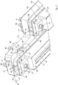
- the printing unit 12 comprises at least one positioning member, in this case shown in figs. 3a, 3b , 4 , 5, 6a, 6b, 7a and 7b , a first positioning member 45a and a second positioning member 45b, associated with the support plate 15 and the printing head 20 to adjust the position of the printing head 20 with respect to the support plate 15.
- the first positioning member 45a and the second positioning member 45b each comprise at least an actuation device 50, able to be selectively actuated above the adjustment plane ⁇ and a kinematic conversion device 46 configured to convert the actuation of the actuation device 50 into an adjustment of the position of the printing head 20 with respect to the support plate 15 in at least one direction lying on the adjustment plane ⁇ .
- This possibility of adjusting the position is advantageous for compensating possible misalignments of the printing heads 20 due to irregularities in the mechanical workings performed to produce at least the support plate 15 and the printing heads 20.
- the first positioning member 45a is configured to perform an adjustment of the position of the printing head 20 in a first adjustment direction M and the second positioning member 45b is configured to perform an adjustment of the position of the printing head 20 in a second adjustment direction R, different from the first adjustment direction M.
- the first adjustment direction M and the second adjustment direction R both lie on the adjustment plane ⁇ .
- the first adjustment direction M and/or the second adjustment direction R can be chosen from a group comprising a translation or a rotation.
- the first adjustment direction M comprises a translation in a direction transverse to the direction of printing Y.
- the second adjustment direction R comprises a rotation of the printing head 20 on the adjustment plane ⁇ .
- the printing head 20 and the support plate 15 are provided respectively with an eyelet 54 and a pin 56, or vice versa, positioned in the eyelet 54.
- the eyelet 54 and the pin 56 are configured to allow a translation in the first adjustment direction M and a rotation in the second adjustment direction R of the printing head 20 with respect to the support plate 15.
- the eyelet 54 is made in the printing head 20, while the pin 56 is attached to the support plate 15.
- the eyelet 54 extends in a direction parallel to the first adjustment direction M.
- the printing head 20 is moved so that the pin 56 can both slide in the eyelet 54, determining a translation of the printing head 20 in the first adjustment direction M, and can also rotate around the eyelet 54, determining a rotation of the printing head 20 in the second adjustment direction R.
- the first positioning member 45a is disposed in correspondence with a first lateral edge of the printing head 20, while the second positioning member 45b is disposed in correspondence with a second lateral edge of the printing head 20 located transverse with respect to the first lateral edge.
- the actuation device 50 has an actuation axis Z that is incident against the adjustment plane ⁇ .
- the actuation device 50 can be driven in rotation around the actuation axis Z, and the kinematic conversion device 46 is configured to convert the rotational motion received from the actuation device 50 into a positioning motion of the printing head 20 lying on the adjustment plane ⁇ .
- the actuation device 50 is connected to the support plate 15 and to the kinematic conversion device 46. In this way the support plate 15 supplies a reference point for the movement of the printing head 20 with respect to the support plate 15.
- the actuation device 50 comprises a screw 51 installed on the support plate 15, rotatable around the actuation axis Z and constrained in translation along the actuation axis Z.
- the screw 51 is in turn connected to the kinematic conversion device 46.
- the kinematic conversion device 46 comprises a cam element, for example a shaped block 48, connected to the actuation device 50, and at least an abutment wall of a seating 58 made in the frame 22 of the printing head 20 and configured to cooperate with the shaped block 48 so that an adjustment of the position of the printing head 20 on the adjustment plane ⁇ corresponds to a movement of the shaped block 48.
- the abutment wall of the seating 58 is disposed inclined by an angle other than 90° with respect to the adjustment plane ⁇ and that the shaped block 48 is able to move sliding and resting along the abutment wall of the seating 58.
- the actuation device 50 is configured to move the shaped block 48 linearly along an axis parallel to the actuation axis Z, moving it perpendicular to the adjustment plane ⁇ of the printing heads 20.
- the shaped block 48 can have the form of a prism with a parallelogram base, in which the inclined sides are disposed resting on the abutment wall of the seating 58.
- the shaped block 48 can comprise a hole 52 into which the screw 51 of the actuation device 50 is screwed.
- the support plate 15 can comprise cavities 70 configured to collaborate with the kinematic conversion device 46, for example to house the shaped block 48.
- the actuation device 50 comprises a screw 51 substantially analogous to that described above and that the kinematic conversion device 46 is defined only by an abutment wall of the seating 58 made in the printing head 20, inclined by an angle other than 90° with respect to the adjustment plane ⁇ , and on which the terminal end of the screw 51 is made to thrust.
- the vertical movement of the screw 51, due to its screwing/unscrewing, and the cooperation of the terminal end of the screw 51 with the abutment wall of the seating 58 made in the printing head 20 allows to obtain the movement of the latter with respect to the support plate 15 and on the adjustment plane ⁇ .
- the shaped block 48 By activating the actuation element 50, the shaped block 48 is made to move along an axis parallel to the actuation axis Z in the direction of arrow F1 (see fig. 6a ). Due to the interference between the shaped block 48 and the abutment wall of the seating 58, a movement is determined of the printing head 20 in the direction of arrow L1 which corresponds to a translation with respect to the axis X, concordant with arrow M.
- the shaped block 48 can be inside the abutment wall of the seating 58, determining a second limit position of the printing head 20 with respect to the support plate 15.
- the shaped block 48 By activating the actuation element 50, in the direction opposite to the previous one, the shaped block 48 is made to move along an axis parallel to the actuation axis Z in the direction of arrow F2. Due to the interference between the shaped block 48 and the abutment wall of the seating 58, a movement is determined of the printing head 20 in the direction of arrow L2 which corresponds to a translation with respect to the axis X, in the opposite direction to the previous one, concordant with arrow M.
- the shaped block 48 can be inside the cavity 70, determining a first limit position of the printing head 20 with respect to the support plate 15.
- the shaped block 48 By activating the actuation element 50, the shaped block 48 is made to move along an axis parallel to the actuation axis Z in the direction of arrow F1. Due to the interference between the shaped block 48 and the abutment wall of the seating 58, a movement is determined of the printing head 20 in the direction of arrow L1 which corresponds to a rotation of the printing head 20 with respect to the pin 56, concordant with the second adjustment direction R.
- the shaped block 48 By activating the actuation element 50, in the direction opposite to the previous one, the shaped block 48 is made to move along an axis parallel to the actuation axis Z in the direction of arrow F2 (see fig. 7b ). Due to the interference between the shaped block 48 and the abutment wall of the seating 58, a movement is determined of the printing head 20 in the direction of arrow L2 which corresponds to a rotation of the printing head 20 with respect to the pin 56 in the opposite direction to the previous one, concordant with the second adjustment direction R.
- the actuation element or device 50 and the shaped block 48 therefore form a screw-female screw coupling that allows the shaped block 48 to be translated in one direction or the other.
- the shaped block 48 in turn behaves like a cam element when the actuation element 50 is activated.
- the translation of the shaped block 48 provided for example in the positioning member 45a, along the abutment walls of the seating 58 of the printing head 20, determines the movement of the printing head 20 in the adjustment direction M.
- the seating 58 made in the frame 22 of the printing head 20 can comprise two suitably inclined abutment walls.
- the abutment walls of the seating 58 are parallel to each other.
- the shaped block 48 represents one of the multiple cam elements that could be used in the positioning member 45a and/or 45b to determine the movement of the printing head 20 in one or more adjustment directions following the activation of the corresponding actuation elements or devices 50.
- the printing head 20 and the support plate 15 holding devices 40 are provided, configured to hold the printing head 20 resting on the support plate 15 and to prevent a movement in an incident direction with respect to the adjustment plane ⁇ .
- the holding devices 40 comprise threaded elements 41 installed in through holes 66 made in the support plate 15 and configured to screw into threaded holes 64 made in the printing head 20.
- the printing heads 20 can be provided with a print dispenser 21 and a frame 22 configured to allow to connect the print dispenser 21 to the support plate 15.
- the print dispenser 21 and the frame 22 could also be made in a single body.
- the holding devices 40 can comprise a counter-frame 32 configured to allow to connect the frame 22 and hence the print dispenser 21 to the corresponding support plate 15.
- the counter-frame 32 can be disposed on the opposite side of the support plate 15 with respect to the one where the frame 22 and the print dispenser 21 are disposed, therefore, during use, frame 22 and print dispenser 21 face toward the substrate 11, while the counter-frame 32 is on the opposite side, which faces upward and is more easily accessible for an operator who wants to make an adjustment.
- Frame 22 and counter-frame 32 can be associated with the support plate 15 by constraining them with attachment elements, in this case the same threaded elements 41 described above. In this way it is possible to maintain and/or replace the printing heads 20 extremely easily.
- the frame 22 can comprise at least one attachment hole 62, preferably at least two attachment holes 62, configured to associate the printing head 20 with the respective frame 22 by holding devices 40.
- the frame 22 can comprise an aperture 60 configured for the passage of connections, not shown in the drawings, to the print dispenser 21.
- the frame 22 can comprise holes 64.
- the support plate 15 can have the through holes 66 mating with the holes 64.
- the counter-frame 32 comprises holes 68 mating with the holes 64 of the respective frame 22.
- the holes 64 and the corresponding holes 68 can be suitably aligned so as to be able to constrain the frame 22 to the support plate 15, once the desired position of one with respect to the other has been adjusted and obtained, by clamping the holding devices 40 onto the frame 22 and counter-frame 32.
- the through holes 66 have cross section sizes greater than those of the holes 64, 68, thus allowing a possibility of moving the printing head 20 on the adjustment plane ⁇ .
- each printing head 20 can comprise a compensation plate 42 installed between the print dispenser 21 and the corresponding frame 22.
- the compensation plate 42 can be made of brass for example or other suitable material.
- each printing head 20 can also comprise a second compensation plate 44.
- the second compensation plate 44 can be installed for example between the print dispenser 21 and the compensation plate 42.
- Each print dispenser 21 is provided with respective nozzles 34 configured to perform the correct printing sequence and to dispense the pre-set materials and colors.
- the nozzles 34 must be correctly aligned in order to obtain a precise printing, defined and well-made on the substrate 11.
- each printing unit 12 can comprise one or more feed devices 18, suitable to supply an adequate quantity of print material, such as color, for example the primary colors (cyan, magenta and yellow), the neutral colors (black and white), as well as possible specific materials in order to confer, for example, shiny/opaque effects or also additives such as glitter, on the printing heads 20.
- print material such as color, for example the primary colors (cyan, magenta and yellow), the neutral colors (black and white), as well as possible specific materials in order to confer, for example, shiny/opaque effects or also additives such as glitter, on the printing heads 20.
- the feed devices 18 can comprise for example members to recirculate the print material in the printing heads 20.
- the feed devices 18 can be connected to tanks that contain the print material suitable to make this available to the printing heads 20.
- a respective control board 24 is associated with each printing head 20, provided to command the selective functioning of the printing head 20 and possibly of the feed devices 18.
- Each printing head 20, the respective control board 24 and possibly the respective feed devices 18 together define a printing module 16.
- Each printing unit 12 comprises at least one of the printing modules 16, preferably a plurality, for example two, three or as in the case shown in fig. 1 , each printing unit 12 comprises four printing modules 16.
- printing units 12 of a modular type are obtained, selectively installable/replaceable on the printing apparatus 10 quickly and easily, even by non-specialized staff.
- the printing unit 12 can comprise a support board 28 configured to support and connect the respective printing modules 16.
- the support plate 15 can comprise an electric connector 30.
- the electric cables are made on the support board 28 and that the latter is connected to the electric connector 30.
- the feed devices 18 can comprise entrance/exit connectors 36 configured to make the print material flow to the printing heads 20 and allow to recirculate excess print material.
- the printing heads 20 can comprise entrance/exit connectors 38 to supply print material to be deposited on the substrate 11.
- the printing modules 16 comprise connection elements such as thin tubes or pipes, not shown in the drawings, to supply print material from the tank 18 to the printing heads 20 and/or vice versa to recover print material from the printing heads 20 to the tank 18.
- the printing heads 20 can cooperate with a drying device, normally a UV lamp, not shown in the drawings, to dry the print material deposited on the substrate 11 substantially instantaneously.
- a drying device normally a UV lamp, not shown in the drawings
- the printing apparatus 10 can comprise a flat stabilizing plate 72 configured to surround the printing heads 20 and make the print surface uniform above the substrate 11 to be printed, so as to reduce possible turbulence deriving from the sliding of the latter. In this way it is possible to reduce turbulence that can be generated with the sliding of the substrate 11 and that deflects the print jet during deposition.
- the stabilizing plate 72 comprises housings 74, mating in shape with the printing heads 20, and in which, during use, the printing heads 20 are at least partly positioned through, in order to make the surface as uniform and flat as possible.
- the stabilizing plate 72 and the support plates 15 can comprise reference elements 75 to maintain the desired position if one or more support plates 15 were to be replaced.
- the reference elements 75 can comprise eyelets 76 made in the stabilizing plate 72 and pins 78 protruding from the support plates 15, coordinated with the eyelets 76. It is obvious that the position of eyelets 76 and pins 78 can also be inverted or combined between the stabilizing plate 72 and the support plates 15.
Landscapes
- Engineering & Computer Science (AREA)
- Quality & Reliability (AREA)
- Ink Jet (AREA)
- Inking, Control Or Cleaning Of Printing Machines (AREA)
- Rotary Presses (AREA)
- Paper (AREA)
- Coating Apparatus (AREA)
Claims (12)
- Druckwerk, umfassend mindestens einen Druckkopf (20) und eine Trägerplatte (15), der der Druckkopf (20) zugeordnet ist, wobei:das Druckwerk mindestens zwei unabhängige und getrennte Positioniervorrichtungen (45a, 45b) aufweist, die der Trägerplatte (15) und dem Druckkopf (20) zugeordnet sind, um die wechselseitige Position der Trägerplatte (15) und des Druckkopfs (20) einzustellen, wobei eine erste Positioniervorrichtung (45a) bezüglich einer ersten lateralen Kante des Druckkopfs (20) angeordnet ist, während eine zweite Positioniervorrichtung (45b) bezüglich einer zweiten lateralen Kante des Druckkopfs (20), die transversal zu der ersten lateralen Kante verortet ist, angeordnet ist; wobeidie Trägerplatte (15) eine Justierebene (α) definiert, bezüglich derer der Druckkopf (20) positioniert wird, wobei die Positioniervorrichtungen (45a, 45b) mindestens eine Betätigungsvorrichtung (50) aufweisen, die selektiv über der Justierebene (α) betätigt werden kann, und eine kinematischen Umsetzvorrichtung (46), die dazu eingerichtet ist, das Betätigen der Betätigungsvorrichtung (50) in ein Einstellen der Position des Druckkopfs (20) bezüglich der Trägerplatte (15) entlang mindestens einer Richtung in der Justierebene (α) umzusetzen; wobeidie Betätigungsvorrichtung (50) einem Verschiebeelement (48) zuordenbar ist, das mit einer Aufnahme (58) von geeigneter Form, die in dem Druckkopf (20) ausgebildet ist, koppeln kann; wobeidie erste Positioniervorrichtung (45a) dazu eingerichtet ist, ein Einstellen der Position des Druckkopfs (20) entlang einer ersten Justierrichtung (M) auszuführen; und wobeidie zweite Positioniervorrichtung (45b) dazu eingerichtet ist, ein Einstellen der Position des Druckkopfs (20) entlang einer zweiten Justierrichtung (R) auszuführen, die von der ersten Justierrichtung (M) verschieden ist.
- Druckwerk nach Anspruch 1, bei dem die Betätigungsvorrichtung (50) und das Verschiebeelement (48) einander mittels zweier gekoppelter Schraubverbinder zugeordnet werden können.
- Druckwerk nach Anspruch 1, bei dem die erste Justierrichtung (M) eine Translation entlang einer Richtung transversal zur Druckrichtung (Y) aufweist.
- Druckwerk nach Anspruch 1, bei dem die zweite Justierrichtung (R) eine Rotation des Druckkopfes (20) auf der Justierebene (α) umfasst.
- Druckwerk nach einem der Ansprüche 1 bis 4, bei dem der Druckkopf (20) und die Trägerplatte (15) mit einer Öffnung (54) beziehungsweise einem Stift (56) ausgebildet sind, oder umgekehrt, wobei der Stift in der Öffnung (54) angeordnet ist, und wobei die Öffnung (54) und der Stift (56) dazu eingerichtet sind, eine Translation entlang der ersten Justierrichtung (M) und eine Rotation entlang der zweiten Justierrichtung (R) des Druckkopfs (20) bezüglich der Trägerplatte (15) zuzulassen.
- Druckwerk nach einem der vorhergehenden Ansprüche, bei dem die Betätigungsvorrichtung (50) eine Betätigungsachse (Z) aufweist, die einfallend auf die Justierebene (α) ist.
- Druckwerk nach Anspruch 6, bei dem die Betätigungsvorrichtung (50) in eine Drehung um die Betätigungsachse (Z) versetzt werden kann und die kinematische Umsetzvorrichtung (46) dazu eingerichtet ist, die von der Betätigungsvorrichtung (50) empfangene Drehbewegung in eine Positionierbewegung des auf der Justierebene (α) aufliegenden Druckkopfs (20) umzusetzen.
- Druckwerk nach einem der vorhergehenden Ansprüche, bei dem das Verschiebeelement (48), das der Betätigungsvorrichtung (50) zuordenbar ist, an mindestens einer Auflagewand der Aufnahme (58), die im Druckkopf (20) ausgebildet ist, ankoppeln kann, so dass ein Einstellen der Position des Druckkopfs (20) auf der Justierebene (α) einer Bewegung des Verschiebeelements (48) entspricht.
- Druckwerk nach Anspruch 6, bei dem die Betätigungsvorrichtung (50) dazu eingerichtet ist, das Verschiebeelement (48) linear entlang einer zur Betätigungsachse (Z) parallelen Achse zu bewegen, wobei sie es senkrecht zu der Justierebene (α) des Druckkopfs (20) bewegt.
- Druckwerk nach einem der vorhergehenden Ansprüche, bei dem Haltevorrichtungen (40) zwischen dem Druckkopf (20) und der Trägerplatte (15) ausgebildet sind, die dazu eingerichtet sind, den auf der Trägerplatte (15) aufliegenden Druckkopf (20) zu halten und eine Bewegung entlang einer auf die Justierebene (α) einfallenden Richtung zu verhindern.
- Druckmaschine, umfassend mindestens eine Trägerebene (14), auf der ein zu bedruckendes Substrat (11) angeordnet werden kann; weiterhin umfassend ein Druckwerk (12) nach einem der vorhergehenden Ansprüche.
- Verfahren zum Drucken, umfassend mindestens einen Schritt zum Einstellen einer Position eines Druckkopfs (20) bezüglich einer Trägerplatte (15) mittels mindestens zweier unabhängiger und getrennter Positioniervorrichtungen (45a, 45b), wobei
eine erste Positioniervorrichtung (45a) bezüglich einer ersten lateralen Kante des Druckkopfs (20) angeordnet ist, während eine zweite Positioniervorrichtung (45b) bezüglich einer zweiten lateralen Kante des Druckkopfs (20), die transversal zu der ersten lateralen Kante verortet ist, angeordnet ist; wobei
die Trägerplatte (15) eine Justierebene (α) definiert, bezüglich derer der Druckkopf (20) positioniert wird; wobei
während des Schrittes zum Einstellen der Position des Druckkopfs (20) folgende Schritte ausgeführt werden:Antreiben einer Betätigungsvorrichtung (50) über der Justierebene (a); undUmsetzen, mittels einer kinematischen Umsetzvorrichtung (46), des Betätigens der Betätigungsvorrichtung (50) in ein Einstellen der Position des Druckkopfs (20) bezüglich der Trägerplatte (15) entlang mindestens einer Richtung in der Justierebene (a); wobei das Umsetzen mittels mindestens eines Verschiebeelements (48) durchgeführt wird, das mit der Betätigungsvorrichtung (50) und dem Druckkopf (20) zusammenwirkt; wobeidie erste Positioniervorrichtung (45a) dazu eingerichtet ist, ein Einstellen der Position des Druckkopfs (20) entlang einer ersten Richtung (M) durchzuführen; und wobeidie zweite Positioniervorrichtung (45b) dazu eingerichtet ist, ein Einstellen der Position des Druckkopfs (20) entlang einer zweiten Richtung (R) durchzuführen, die von der ersten Richtung (M) verschieden ist.
Priority Applications (1)
| Application Number | Priority Date | Filing Date | Title |
|---|---|---|---|
| PL16190510T PL3147128T3 (pl) | 2015-09-25 | 2016-09-23 | Zespół drukujący do aparatu drukującego i aparat drukujący zawierający wspomniany zespół drukujący |
Applications Claiming Priority (1)
| Application Number | Priority Date | Filing Date | Title |
|---|---|---|---|
| ITUB2015A003900A ITUB20153900A1 (it) | 2015-09-25 | 2015-09-25 | Gruppo di stampa per un apparato di stampa ed apparato di stampa comprendente detto gruppo di stampa |
Publications (2)
| Publication Number | Publication Date |
|---|---|
| EP3147128A1 EP3147128A1 (de) | 2017-03-29 |
| EP3147128B1 true EP3147128B1 (de) | 2020-11-04 |
Family
ID=55085743
Family Applications (1)
| Application Number | Title | Priority Date | Filing Date |
|---|---|---|---|
| EP16190510.4A Active EP3147128B1 (de) | 2015-09-25 | 2016-09-23 | Druckeinheit für eine druckvorrichtung und druckvorrichtung mit dieser druckeinheit |
Country Status (6)
| Country | Link |
|---|---|
| US (1) | US10124613B2 (de) |
| EP (1) | EP3147128B1 (de) |
| CN (1) | CN206446276U (de) |
| ES (1) | ES2836398T3 (de) |
| IT (1) | ITUB20153900A1 (de) |
| PL (1) | PL3147128T3 (de) |
Cited By (1)
| Publication number | Priority date | Publication date | Assignee | Title |
|---|---|---|---|---|
| IT202300007275A1 (it) | 2023-04-14 | 2024-10-14 | Spider Jet S R L | Testa di stampa per stampanti |
Families Citing this family (7)
| Publication number | Priority date | Publication date | Assignee | Title |
|---|---|---|---|---|
| CN110154544B (zh) * | 2018-02-12 | 2020-11-24 | 海德堡印刷机械股份公司 | 用于喷墨的印刷杆 |
| JP7333927B2 (ja) * | 2018-03-16 | 2023-08-28 | コニカミノルタ株式会社 | ヘッドモジュール、インクジェット記録装置及びインクジェットヘッドの位置調整方法 |
| JP7265421B2 (ja) * | 2019-06-07 | 2023-04-26 | エスアイアイ・プリンテック株式会社 | 液体噴射ヘッドおよび液体噴射記録装置 |
| CN112319070B (zh) * | 2020-09-18 | 2022-05-10 | 季华实验室 | 一种三维微调装置和喷墨打印设备 |
| WO2023122474A1 (en) * | 2021-12-21 | 2023-06-29 | Kateeva, Inc. | Printhead alignment |
| DE102022100700A1 (de) * | 2022-01-13 | 2023-07-13 | Kolbus Gmbh & Co. Kg | Druckvorrichtung zum individuellen Bedrucken von bahnförmigen oder bogenförmigen Bedruckstoffen |
| AU2023278980B2 (en) * | 2022-06-02 | 2025-10-30 | Memjet Technology Limited | Inkjet module with printhead nest assembly |
Family Cites Families (9)
| Publication number | Priority date | Publication date | Assignee | Title |
|---|---|---|---|---|
| US5289208A (en) * | 1991-10-31 | 1994-02-22 | Hewlett-Packard Company | Automatic print cartridge alignment sensor system |
| US6213580B1 (en) * | 1998-02-25 | 2001-04-10 | Xerox Corporation | Apparatus and method for automatically aligning print heads |
| US6341845B1 (en) * | 2000-08-25 | 2002-01-29 | Hewlett-Packard Company | Electrical connection for wide-array inkjet printhead assembly with hybrid carrier for printhead dies |
| US7073883B2 (en) * | 2003-10-16 | 2006-07-11 | Eastman Kodak Company | Method of aligning inkjet nozzle banks for an inkjet printer |
| ATE471239T1 (de) * | 2004-04-30 | 2010-07-15 | Dimatix Inc | Rezirkulationsanordnung |
| JP5423019B2 (ja) * | 2008-07-04 | 2014-02-19 | 株式会社リコー | 液体吐出ヘッドユニット及び画像形成装置 |
| JP2010264700A (ja) * | 2009-05-15 | 2010-11-25 | Seiko Epson Corp | 液体噴射ヘッドユニットの製造方法及び液体噴射装置 |
| JP5412306B2 (ja) * | 2010-01-27 | 2014-02-12 | 株式会社ミヤコシ | インクジェット印字装置 |
| US8297736B2 (en) * | 2010-08-20 | 2012-10-30 | Ffei Limited | Inkjet head support assembly |
-
2015
- 2015-09-25 IT ITUB2015A003900A patent/ITUB20153900A1/it unknown
-
2016
- 2016-09-23 PL PL16190510T patent/PL3147128T3/pl unknown
- 2016-09-23 US US15/275,071 patent/US10124613B2/en active Active
- 2016-09-23 EP EP16190510.4A patent/EP3147128B1/de active Active
- 2016-09-23 ES ES16190510T patent/ES2836398T3/es active Active
- 2016-09-26 CN CN201621082942.XU patent/CN206446276U/zh not_active Expired - Fee Related
Non-Patent Citations (1)
| Title |
|---|
| None * |
Cited By (1)
| Publication number | Priority date | Publication date | Assignee | Title |
|---|---|---|---|---|
| IT202300007275A1 (it) | 2023-04-14 | 2024-10-14 | Spider Jet S R L | Testa di stampa per stampanti |
Also Published As
| Publication number | Publication date |
|---|---|
| CN206446276U (zh) | 2017-08-29 |
| ITUB20153900A1 (it) | 2017-03-25 |
| US20170087904A1 (en) | 2017-03-30 |
| ES2836398T3 (es) | 2021-06-25 |
| EP3147128A1 (de) | 2017-03-29 |
| PL3147128T3 (pl) | 2021-04-19 |
| US10124613B2 (en) | 2018-11-13 |
Similar Documents
| Publication | Publication Date | Title |
|---|---|---|
| US10124613B2 (en) | Printing unit for a printing apparatus and printing apparatus comprising said printing unit | |
| US10029455B2 (en) | Printing apparatus | |
| EP2897805B1 (de) | Druckbalkenbefestigungssysteme und entsprechende strukturen | |
| RU2538864C2 (ru) | Однопроходный струйный принтер | |
| KR100848162B1 (ko) | 잉크젯 프린팅 장치 및 헤드위치 조절방법 | |
| US8016384B2 (en) | Image forming apparatus | |
| US20090295878A1 (en) | Jetting module installation and alignment apparatus | |
| US20160375707A1 (en) | Mounting structure for a plurality of print head units | |
| DE19743804A1 (de) | Druckvorrichtung | |
| WO2018080160A1 (ko) | 가변 노즐이 구비된 슬롯 다이 | |
| WO2016104126A1 (ja) | インクジェットヘッドの取付構造、キャリッジ及びインクジェット記録装置 | |
| JP2016107401A (ja) | ヘッドモジュール、インクジェット記録装置及びヘッドモジュールの組み立て方法 | |
| US20110063368A1 (en) | Multi inkjet head package, inkjet recording apparatus using the same, and method of aligning the same in inkjet recording apparatus | |
| US20160031238A1 (en) | Printhead attachment system | |
| KR101226762B1 (ko) | 스크린프린터의 인쇄회로기판 유동방지 고정장치 | |
| KR20080015651A (ko) | 잉크젯 프린팅 장비의 헤드 정렬 장치 | |
| US9421769B2 (en) | Liquid ejecting head, liquid ejecting head unit, liquid ejecting apparatus, and method of manufacturing liquid ejecting head unit | |
| US7669947B2 (en) | Industrial ink jet print head system | |
| KR102291007B1 (ko) | 헤드 위치조절부를 구비한 액적 토출장치 | |
| WO2010101034A1 (ja) | キャリッジユニット、液体噴射記録装置および液体噴射ヘッドの固定方法 | |
| US9079402B2 (en) | Printer having a global skew adjustment and a print head assembly having an adjustment mechanism | |
| NO140562B (no) | Ventilbaereplate for straale-fargeapparat | |
| KR102548020B1 (ko) | 다이렉트-투-오브젝트 프린터에서 자외선 경화성 잉크로 3차원 물체 상에 인쇄하기 위한 시스템 및 방법 | |
| EP3037271B1 (de) | Druckeinheit für eine druckvorrichtung und druckvorrichtung mit dieser druckeinheit | |
| JP2007098648A (ja) | 建築板の塗装装置 |
Legal Events
| Date | Code | Title | Description |
|---|---|---|---|
| PUAI | Public reference made under article 153(3) epc to a published international application that has entered the european phase |
Free format text: ORIGINAL CODE: 0009012 |
|
| STAA | Information on the status of an ep patent application or granted ep patent |
Free format text: STATUS: THE APPLICATION HAS BEEN PUBLISHED |
|
| AK | Designated contracting states |
Kind code of ref document: A1 Designated state(s): AL AT BE BG CH CY CZ DE DK EE ES FI FR GB GR HR HU IE IS IT LI LT LU LV MC MK MT NL NO PL PT RO RS SE SI SK SM TR |
|
| AX | Request for extension of the european patent |
Extension state: BA ME |
|
| STAA | Information on the status of an ep patent application or granted ep patent |
Free format text: STATUS: REQUEST FOR EXAMINATION WAS MADE |
|
| 17P | Request for examination filed |
Effective date: 20170929 |
|
| RBV | Designated contracting states (corrected) |
Designated state(s): AL AT BE BG CH CY CZ DE DK EE ES FI FR GB GR HR HU IE IS IT LI LT LU LV MC MK MT NL NO PL PT RO RS SE SI SK SM TR |
|
| GRAP | Despatch of communication of intention to grant a patent |
Free format text: ORIGINAL CODE: EPIDOSNIGR1 |
|
| STAA | Information on the status of an ep patent application or granted ep patent |
Free format text: STATUS: GRANT OF PATENT IS INTENDED |
|
| RIC1 | Information provided on ipc code assigned before grant |
Ipc: B41J 2/155 20060101ALI20200612BHEP Ipc: B41J 25/34 20060101ALI20200612BHEP Ipc: B41J 2/21 20060101AFI20200612BHEP Ipc: B41J 25/00 20060101ALI20200612BHEP |
|
| INTG | Intention to grant announced |
Effective date: 20200714 |
|
| RAP1 | Party data changed (applicant data changed or rights of an application transferred) |
Owner name: JET-SET SRL |
|
| GRAS | Grant fee paid |
Free format text: ORIGINAL CODE: EPIDOSNIGR3 |
|
| GRAA | (expected) grant |
Free format text: ORIGINAL CODE: 0009210 |
|
| STAA | Information on the status of an ep patent application or granted ep patent |
Free format text: STATUS: THE PATENT HAS BEEN GRANTED |
|
| AK | Designated contracting states |
Kind code of ref document: B1 Designated state(s): AL AT BE BG CH CY CZ DE DK EE ES FI FR GB GR HR HU IE IS IT LI LT LU LV MC MK MT NL NO PL PT RO RS SE SI SK SM TR |
|
| REG | Reference to a national code |
Ref country code: GB Ref legal event code: FG4D |
|
| REG | Reference to a national code |
Ref country code: CH Ref legal event code: NV Representative=s name: NOVAGRAAF INTERNATIONAL SA, CH Ref country code: CH Ref legal event code: EP |
|
| REG | Reference to a national code |
Ref country code: AT Ref legal event code: REF Ref document number: 1330317 Country of ref document: AT Kind code of ref document: T Effective date: 20201115 |
|
| REG | Reference to a national code |
Ref country code: DE Ref legal event code: R096 Ref document number: 602016047044 Country of ref document: DE |
|
| REG | Reference to a national code |
Ref country code: IE Ref legal event code: FG4D |
|
| REG | Reference to a national code |
Ref country code: NL Ref legal event code: MP Effective date: 20201104 |
|
| REG | Reference to a national code |
Ref country code: AT Ref legal event code: MK05 Ref document number: 1330317 Country of ref document: AT Kind code of ref document: T Effective date: 20201104 |
|
| PG25 | Lapsed in a contracting state [announced via postgrant information from national office to epo] |
Ref country code: FI Free format text: LAPSE BECAUSE OF FAILURE TO SUBMIT A TRANSLATION OF THE DESCRIPTION OR TO PAY THE FEE WITHIN THE PRESCRIBED TIME-LIMIT Effective date: 20201104 Ref country code: GR Free format text: LAPSE BECAUSE OF FAILURE TO SUBMIT A TRANSLATION OF THE DESCRIPTION OR TO PAY THE FEE WITHIN THE PRESCRIBED TIME-LIMIT Effective date: 20210205 Ref country code: NO Free format text: LAPSE BECAUSE OF FAILURE TO SUBMIT A TRANSLATION OF THE DESCRIPTION OR TO PAY THE FEE WITHIN THE PRESCRIBED TIME-LIMIT Effective date: 20210204 Ref country code: PT Free format text: LAPSE BECAUSE OF FAILURE TO SUBMIT A TRANSLATION OF THE DESCRIPTION OR TO PAY THE FEE WITHIN THE PRESCRIBED TIME-LIMIT Effective date: 20210304 Ref country code: RS Free format text: LAPSE BECAUSE OF FAILURE TO SUBMIT A TRANSLATION OF THE DESCRIPTION OR TO PAY THE FEE WITHIN THE PRESCRIBED TIME-LIMIT Effective date: 20201104 |
|
| PG25 | Lapsed in a contracting state [announced via postgrant information from national office to epo] |
Ref country code: AT Free format text: LAPSE BECAUSE OF FAILURE TO SUBMIT A TRANSLATION OF THE DESCRIPTION OR TO PAY THE FEE WITHIN THE PRESCRIBED TIME-LIMIT Effective date: 20201104 Ref country code: BG Free format text: LAPSE BECAUSE OF FAILURE TO SUBMIT A TRANSLATION OF THE DESCRIPTION OR TO PAY THE FEE WITHIN THE PRESCRIBED TIME-LIMIT Effective date: 20210204 Ref country code: IS Free format text: LAPSE BECAUSE OF FAILURE TO SUBMIT A TRANSLATION OF THE DESCRIPTION OR TO PAY THE FEE WITHIN THE PRESCRIBED TIME-LIMIT Effective date: 20210304 Ref country code: LV Free format text: LAPSE BECAUSE OF FAILURE TO SUBMIT A TRANSLATION OF THE DESCRIPTION OR TO PAY THE FEE WITHIN THE PRESCRIBED TIME-LIMIT Effective date: 20201104 Ref country code: SE Free format text: LAPSE BECAUSE OF FAILURE TO SUBMIT A TRANSLATION OF THE DESCRIPTION OR TO PAY THE FEE WITHIN THE PRESCRIBED TIME-LIMIT Effective date: 20201104 |
|
| REG | Reference to a national code |
Ref country code: LT Ref legal event code: MG9D |
|
| REG | Reference to a national code |
Ref country code: ES Ref legal event code: FG2A Ref document number: 2836398 Country of ref document: ES Kind code of ref document: T3 Effective date: 20210625 |
|
| PG25 | Lapsed in a contracting state [announced via postgrant information from national office to epo] |
Ref country code: HR Free format text: LAPSE BECAUSE OF FAILURE TO SUBMIT A TRANSLATION OF THE DESCRIPTION OR TO PAY THE FEE WITHIN THE PRESCRIBED TIME-LIMIT Effective date: 20201104 |
|
| PG25 | Lapsed in a contracting state [announced via postgrant information from national office to epo] |
Ref country code: RO Free format text: LAPSE BECAUSE OF FAILURE TO SUBMIT A TRANSLATION OF THE DESCRIPTION OR TO PAY THE FEE WITHIN THE PRESCRIBED TIME-LIMIT Effective date: 20201104 Ref country code: SK Free format text: LAPSE BECAUSE OF FAILURE TO SUBMIT A TRANSLATION OF THE DESCRIPTION OR TO PAY THE FEE WITHIN THE PRESCRIBED TIME-LIMIT Effective date: 20201104 Ref country code: SM Free format text: LAPSE BECAUSE OF FAILURE TO SUBMIT A TRANSLATION OF THE DESCRIPTION OR TO PAY THE FEE WITHIN THE PRESCRIBED TIME-LIMIT Effective date: 20201104 Ref country code: LT Free format text: LAPSE BECAUSE OF FAILURE TO SUBMIT A TRANSLATION OF THE DESCRIPTION OR TO PAY THE FEE WITHIN THE PRESCRIBED TIME-LIMIT Effective date: 20201104 Ref country code: EE Free format text: LAPSE BECAUSE OF FAILURE TO SUBMIT A TRANSLATION OF THE DESCRIPTION OR TO PAY THE FEE WITHIN THE PRESCRIBED TIME-LIMIT Effective date: 20201104 Ref country code: CZ Free format text: LAPSE BECAUSE OF FAILURE TO SUBMIT A TRANSLATION OF THE DESCRIPTION OR TO PAY THE FEE WITHIN THE PRESCRIBED TIME-LIMIT Effective date: 20201104 |
|
| REG | Reference to a national code |
Ref country code: DE Ref legal event code: R097 Ref document number: 602016047044 Country of ref document: DE |
|
| PG25 | Lapsed in a contracting state [announced via postgrant information from national office to epo] |
Ref country code: DK Free format text: LAPSE BECAUSE OF FAILURE TO SUBMIT A TRANSLATION OF THE DESCRIPTION OR TO PAY THE FEE WITHIN THE PRESCRIBED TIME-LIMIT Effective date: 20201104 |
|
| PLBE | No opposition filed within time limit |
Free format text: ORIGINAL CODE: 0009261 |
|
| STAA | Information on the status of an ep patent application or granted ep patent |
Free format text: STATUS: NO OPPOSITION FILED WITHIN TIME LIMIT |
|
| 26N | No opposition filed |
Effective date: 20210805 |
|
| PG25 | Lapsed in a contracting state [announced via postgrant information from national office to epo] |
Ref country code: AL Free format text: LAPSE BECAUSE OF FAILURE TO SUBMIT A TRANSLATION OF THE DESCRIPTION OR TO PAY THE FEE WITHIN THE PRESCRIBED TIME-LIMIT Effective date: 20201104 Ref country code: NL Free format text: LAPSE BECAUSE OF FAILURE TO SUBMIT A TRANSLATION OF THE DESCRIPTION OR TO PAY THE FEE WITHIN THE PRESCRIBED TIME-LIMIT Effective date: 20201104 |
|
| PG25 | Lapsed in a contracting state [announced via postgrant information from national office to epo] |
Ref country code: SI Free format text: LAPSE BECAUSE OF FAILURE TO SUBMIT A TRANSLATION OF THE DESCRIPTION OR TO PAY THE FEE WITHIN THE PRESCRIBED TIME-LIMIT Effective date: 20201104 |
|
| GBPC | Gb: european patent ceased through non-payment of renewal fee |
Effective date: 20210923 |
|
| PG25 | Lapsed in a contracting state [announced via postgrant information from national office to epo] |
Ref country code: IS Free format text: LAPSE BECAUSE OF FAILURE TO SUBMIT A TRANSLATION OF THE DESCRIPTION OR TO PAY THE FEE WITHIN THE PRESCRIBED TIME-LIMIT Effective date: 20210304 Ref country code: MC Free format text: LAPSE BECAUSE OF FAILURE TO SUBMIT A TRANSLATION OF THE DESCRIPTION OR TO PAY THE FEE WITHIN THE PRESCRIBED TIME-LIMIT Effective date: 20201104 |
|
| PG25 | Lapsed in a contracting state [announced via postgrant information from national office to epo] |
Ref country code: LU Free format text: LAPSE BECAUSE OF NON-PAYMENT OF DUE FEES Effective date: 20210923 Ref country code: IE Free format text: LAPSE BECAUSE OF NON-PAYMENT OF DUE FEES Effective date: 20210923 Ref country code: GB Free format text: LAPSE BECAUSE OF NON-PAYMENT OF DUE FEES Effective date: 20210923 |
|
| PGFP | Annual fee paid to national office [announced via postgrant information from national office to epo] |
Ref country code: TR Payment date: 20220825 Year of fee payment: 7 Ref country code: IT Payment date: 20220825 Year of fee payment: 7 Ref country code: DE Payment date: 20220818 Year of fee payment: 7 |
|
| PGFP | Annual fee paid to national office [announced via postgrant information from national office to epo] |
Ref country code: PL Payment date: 20220822 Year of fee payment: 7 Ref country code: FR Payment date: 20220818 Year of fee payment: 7 Ref country code: BE Payment date: 20220822 Year of fee payment: 7 |
|
| PGFP | Annual fee paid to national office [announced via postgrant information from national office to epo] |
Ref country code: ES Payment date: 20221003 Year of fee payment: 7 |
|
| PGFP | Annual fee paid to national office [announced via postgrant information from national office to epo] |
Ref country code: CH Payment date: 20221001 Year of fee payment: 7 |
|
| PG25 | Lapsed in a contracting state [announced via postgrant information from national office to epo] |
Ref country code: HU Free format text: LAPSE BECAUSE OF FAILURE TO SUBMIT A TRANSLATION OF THE DESCRIPTION OR TO PAY THE FEE WITHIN THE PRESCRIBED TIME-LIMIT; INVALID AB INITIO Effective date: 20160923 |
|
| PG25 | Lapsed in a contracting state [announced via postgrant information from national office to epo] |
Ref country code: CY Free format text: LAPSE BECAUSE OF FAILURE TO SUBMIT A TRANSLATION OF THE DESCRIPTION OR TO PAY THE FEE WITHIN THE PRESCRIBED TIME-LIMIT Effective date: 20201104 |
|
| REG | Reference to a national code |
Ref country code: DE Ref legal event code: R119 Ref document number: 602016047044 Country of ref document: DE |
|
| PG25 | Lapsed in a contracting state [announced via postgrant information from national office to epo] |
Ref country code: MK Free format text: LAPSE BECAUSE OF FAILURE TO SUBMIT A TRANSLATION OF THE DESCRIPTION OR TO PAY THE FEE WITHIN THE PRESCRIBED TIME-LIMIT Effective date: 20201104 |
|
| REG | Reference to a national code |
Ref country code: CH Ref legal event code: PL |
|
| REG | Reference to a national code |
Ref country code: BE Ref legal event code: MM Effective date: 20230930 |
|
| PG25 | Lapsed in a contracting state [announced via postgrant information from national office to epo] |
Ref country code: CH Free format text: LAPSE BECAUSE OF NON-PAYMENT OF DUE FEES Effective date: 20230930 |
|
| PG25 | Lapsed in a contracting state [announced via postgrant information from national office to epo] |
Ref country code: FR Free format text: LAPSE BECAUSE OF NON-PAYMENT OF DUE FEES Effective date: 20230930 Ref country code: DE Free format text: LAPSE BECAUSE OF NON-PAYMENT OF DUE FEES Effective date: 20240403 Ref country code: CH Free format text: LAPSE BECAUSE OF NON-PAYMENT OF DUE FEES Effective date: 20230930 |
|
| PG25 | Lapsed in a contracting state [announced via postgrant information from national office to epo] |
Ref country code: BE Free format text: LAPSE BECAUSE OF NON-PAYMENT OF DUE FEES Effective date: 20230930 |
|
| PG25 | Lapsed in a contracting state [announced via postgrant information from national office to epo] |
Ref country code: MT Free format text: LAPSE BECAUSE OF FAILURE TO SUBMIT A TRANSLATION OF THE DESCRIPTION OR TO PAY THE FEE WITHIN THE PRESCRIBED TIME-LIMIT Effective date: 20201104 |
|
| REG | Reference to a national code |
Ref country code: ES Ref legal event code: FD2A Effective date: 20241104 |
|
| PG25 | Lapsed in a contracting state [announced via postgrant information from national office to epo] |
Ref country code: IT Free format text: LAPSE BECAUSE OF NON-PAYMENT OF DUE FEES Effective date: 20230923 |
|
| PG25 | Lapsed in a contracting state [announced via postgrant information from national office to epo] |
Ref country code: IT Free format text: LAPSE BECAUSE OF NON-PAYMENT OF DUE FEES Effective date: 20230923 |
|
| PG25 | Lapsed in a contracting state [announced via postgrant information from national office to epo] |
Ref country code: ES Free format text: LAPSE BECAUSE OF NON-PAYMENT OF DUE FEES Effective date: 20230924 |
|
| PG25 | Lapsed in a contracting state [announced via postgrant information from national office to epo] |
Ref country code: ES Free format text: LAPSE BECAUSE OF NON-PAYMENT OF DUE FEES Effective date: 20230924 |
|
| PG25 | Lapsed in a contracting state [announced via postgrant information from national office to epo] |
Ref country code: PL Free format text: LAPSE BECAUSE OF NON-PAYMENT OF DUE FEES Effective date: 20230923 |