EP3147129B1 - Procédé et dispositif d'impression de récipients - Google Patents
Procédé et dispositif d'impression de récipients Download PDFInfo
- Publication number
- EP3147129B1 EP3147129B1 EP16195559.6A EP16195559A EP3147129B1 EP 3147129 B1 EP3147129 B1 EP 3147129B1 EP 16195559 A EP16195559 A EP 16195559A EP 3147129 B1 EP3147129 B1 EP 3147129B1
- Authority
- EP
- European Patent Office
- Prior art keywords
- container
- module
- containers
- printing
- Prior art date
- Legal status (The legal status is an assumption and is not a legal conclusion. Google has not performed a legal analysis and makes no representation as to the accuracy of the status listed.)
- Not-in-force
Links
Images




Classifications
-
- B—PERFORMING OPERATIONS; TRANSPORTING
- B41—PRINTING; LINING MACHINES; TYPEWRITERS; STAMPS
- B41J—TYPEWRITERS; SELECTIVE PRINTING MECHANISMS, i.e. MECHANISMS PRINTING OTHERWISE THAN FROM A FORME; CORRECTION OF TYPOGRAPHICAL ERRORS
- B41J3/00—Typewriters or selective printing or marking mechanisms characterised by the purpose for which they are constructed
- B41J3/407—Typewriters or selective printing or marking mechanisms characterised by the purpose for which they are constructed for marking on special material
- B41J3/4073—Printing on three-dimensional objects not being in sheet or web form, e.g. spherical or cubic objects
-
- B—PERFORMING OPERATIONS; TRANSPORTING
- B41—PRINTING; LINING MACHINES; TYPEWRITERS; STAMPS
- B41J—TYPEWRITERS; SELECTIVE PRINTING MECHANISMS, i.e. MECHANISMS PRINTING OTHERWISE THAN FROM A FORME; CORRECTION OF TYPOGRAPHICAL ERRORS
- B41J11/00—Devices or arrangements of selective printing mechanisms, e.g. ink-jet printers or thermal printers, for supporting or handling copy material in sheet or web form
- B41J11/0015—Devices or arrangements of selective printing mechanisms, e.g. ink-jet printers or thermal printers, for supporting or handling copy material in sheet or web form for treating before, during or after printing or for uniform coating or laminating the copy material before or after printing
- B41J11/002—Curing or drying the ink on the copy materials, e.g. by heating or irradiating
- B41J11/0021—Curing or drying the ink on the copy materials, e.g. by heating or irradiating using irradiation
- B41J11/00214—Curing or drying the ink on the copy materials, e.g. by heating or irradiating using irradiation using UV radiation
-
- B—PERFORMING OPERATIONS; TRANSPORTING
- B41—PRINTING; LINING MACHINES; TYPEWRITERS; STAMPS
- B41J—TYPEWRITERS; SELECTIVE PRINTING MECHANISMS, i.e. MECHANISMS PRINTING OTHERWISE THAN FROM A FORME; CORRECTION OF TYPOGRAPHICAL ERRORS
- B41J3/00—Typewriters or selective printing or marking mechanisms characterised by the purpose for which they are constructed
- B41J3/407—Typewriters or selective printing or marking mechanisms characterised by the purpose for which they are constructed for marking on special material
- B41J3/4073—Printing on three-dimensional objects not being in sheet or web form, e.g. spherical or cubic objects
- B41J3/40733—Printing on cylindrical or rotationally symmetrical objects, e. g. on bottles
-
- B—PERFORMING OPERATIONS; TRANSPORTING
- B41—PRINTING; LINING MACHINES; TYPEWRITERS; STAMPS
- B41M—PRINTING, DUPLICATING, MARKING, OR COPYING PROCESSES; COLOUR PRINTING
- B41M5/00—Duplicating or marking methods; Sheet materials for use therein
- B41M5/0082—Digital printing on bodies of particular shapes
- B41M5/0088—Digital printing on bodies of particular shapes by ink-jet printing
Definitions
- the present invention relates to a method for printing containers according to the preamble of claim 1 and a device for printing containers according to claim 4.
- Container equipment systems usually apply information to containers which inform the end user of the contents of the container. Their graphic design also serves to promote sales. A typical area of application is the food industry, with a beverage being filled into the containers, for example. In addition to the content information, it may also be necessary to provide the containers with best-before dates for perishable foods. This has been done for a long time by applying printed labels. In recent times, however, developments have also been to dispense with the label material and to print directly on the containers. In systems in which the complete equipment is not carried out in one step, the containers pass through several equipment machines, whereby the space for installing several equipment machines is sometimes very limited. For this purpose, changes of direction in the main conveyor path are necessary, for example in order to be able to implement an alley-shaped arrangement of the equipment machines.
- WO2010 / 034375 A1 describes a device for printing on packaging with multiple printing.
- the object of the invention is to provide a method for printing on containers and a device for printing on containers, which enable flexible equipping of containers with partial print images.
- the invention relates to a method for printing on containers, in which a container of at least two rotating modules, on which rotating printing heads are arranged, is each equipped with a partial print image per module, the containers are transferred directly from one module to the next and the partial print images each have a start and an end edge in the circumferential direction of the container, the container remaining aligned or realigned after the completion of the first partial print image so that the printing of the second partial print image with the Printhead of the following module begins at a peripheral position of the container which is at a distance from the start and end edge of the first partial print image.
- the process is all-round printing.
- the opposite side of the container faces the print head of the following module at the start and end edge of the first partial print.
- printing can begin in the middle of the partial print image of the previous module.
- the distance is equal to 180 °.
- the available treatment angle can be fully used.
- a large number of print heads can be arranged per module at equidistant intervals, which rotate continuously with the module in the direction of rotation.
- the container can remain aligned after the completion of the first partial print image or an alignment can be dispensed with.
- the print heads can lie within the pitch circle of both print modules through which the containers pass, the print heads being directed perpendicularly to an outer wall of the container and each pointing radially outward from a central axis of the modules.
- the container can be rotated in the same direction about its longitudinal axis in both modules during printing.
- the rotation of the container about its longitudinal axis can be stopped before a transfer to the next module takes place.
- the invention relates to a device for printing on containers with a control device, which is designed to carry out a method for printing on containers, as described above or below.
- a container equipment system for printing containers can be a conveyor system for transporting the containers through the equipment system along a predetermined transport route, can be arranged on the conveyor system, in particular permanently arranged, receptacles for receiving individual containers or groups of containers and can comprise at least two peripheral equipment devices for printing on the containers, at least one print head for printing on the containers being arranged on the equipment devices.
- the equipment system can have several modules of the same type. By using individual modules, the system can be flexibly adapted to new requirements that arise at the installation site, in that individual modules can be exchanged, removed or added in a simple manner.
- a container equipment system for equipping containers can be a conveyor system for transporting the containers through the equipment system along a predetermined transport route, can be arranged on the conveyor system, in particular fixedly arranged receptacles for receiving individual containers or groups of containers, can be at least two encircling equipment devices for equipping the containers, wherein a main conveying path of the containers through the equipment system has a change of direction, wherein at least one equipment device is arranged before and one equipment device after the change of direction.
- the transport route in the area of the change of direction has a section which has a curvature that is at least in sections different from that of the upstream equipment device.
- the length of the section is at least one fifth of the distance traveled by the containers in the upstream equipment device.
- Decoration is understood to mean, for example, a surface printing of the container with printing medium.
- the intermediate conveying section without equipment can be used to create space, so to speak, in order to transport the containers to an entry point of the subsequent equipment device which is as favorable as possible.
- the total space requirement of the system may increase slightly, but this is deliberately accepted in order to ensure high performance and utilization of the machines that equip the containers.
- the conveyor section is relatively inexpensive compared to the treatment time gained by it.
- the length of the conveyor section can be at least a quarter or at least a third, or at least half of the transport path of the containers in the upstream equipment device, depending on which angle is to be realized in a main conveyor path.
- the section has in particular a shorter distance to be covered by the containers, than twice the distance that the containers cover in an upstream equipment device.
- the distance of the conveyor section can also be longer.
- the conveying section or the transport route in the area of the change of direction connects an outlet of the equipment device upstream in the transport direction with an inlet of the downstream equipment device such that the containers have a treatment angle of from the inlet to the outlet of the upstream equipment device and from the inlet to the outlet of the downstream equipment device more than 235 °, in particular of more than 265 ° is available.
- the angle information can also be viewed as a function of the time or the distance from one revolution - the specified 265 ° would be two hundred and sixty-five three hundred and sixty-sixths of the route or the period of circulation.
- the conveyor system transports the containers in the area of the rotating equipment devices in particular in such a way that the transport path is concentric to the circulation path of the equipment device, at least in sections.
- the conveyor section can also have a different sign of curvature.
- the containers can also be transported further away from a conveyor in certain embodiment variants of the system, which conveyor is arranged in the transport direction in front of the conveyor which transfers the containers to the conveyor section.
- the curvature of the transport path can also change twice or three times or several times on the conveyor section.
- the conveying section comprises an independent, revolving conveyor, on which a multiplicity of container receptacles, for example in the form of external grippers, in particular clamps, or holder mandrels which grip the container, are arranged.
- This conveyor section as a whole can comprise, for example, a belt conveyor or a rotating transport star.
- the containers are transferred to the receptacles of this conveyor section by the upstream equipment device and transferred from the receptacles of the conveyor to the downstream equipment device. The recordings then run back empty until the next container is assigned to them.
- the conveyor section can also have two or more independent conveyors, e.g. Include funding stars.
- the conveyor system can be attached directly to the equipment. Prefers it is a system similar to that described for the conveyor section - however, the design of the receptacles may differ.
- the conveyor section according to the invention can also comprise a rail instead of a conveyor with its own gripping means for the containers.
- the transport route through which the containers pass is essentially meandering, although depending on the design of the conveyor section arranged in the area of change of direction, there are also linear sections (for example by using a belt transport) can. If the conveyor section also has only rotating transport stars, the meandering shape is continuous, but the angular ranges traversed in the area of the conveyor section can be smaller than those in the area of the equipment devices.
- the equipment stars with means for equipping them can also themselves provide the conveyor system by arranging receptacles for conveying the containers on them.
- the main conveying path is not formed by every differentially small point on the transport route, but by the stations as a whole.
- the main conveyor path can be formed by the connection of the individual transfer points of the containers or bottles from conveyor to conveyor. Another possibility is the result of connecting the centers of several stars.
- At least two equipment devices are provided before and / or after the change of direction.
- the respective two equipment devices can connect directly to one another, i.e. that no intermediate conveyor is placed between them. This has the advantage of a very compact design.
- the equipment devices are advantageously arranged relative to one another such that the containers are equipped along at least two thirds, in particular at least three Quarters, the total scope is possible.
- this corresponds to a continuous angle of the circle segment of at least 240 °, in particular of at least 270 °.
- This can be achieved, for example, by zigzagging the equipment devices relative to one another.
- the zigzag results from the connection of the individual centers (axes of rotation) of the rotary machine.
- a treatment angle of almost 300 ° is possible in this way in this way, but depending on the size of the containers to be treated, a distance must be left for their transport if the equipment is located on the same level.
- the equipment devices are, in particular, devices for direct printing from the container outer surfaces, in particular from the side surfaces along the circumference of the containers.
- several print heads can be provided per equipment device, which apply printing medium to the outer surface of the container.
- the print medium can be ink, paint, varnish or the like, in particular UV-curable ink.
- the print heads in particular have a large number of individually controllable nozzles and operate on the ink jet principle.
- the print heads can be arranged movably on the equipment devices.
- the print heads then run synchronously with it.
- Motorized or manual adjustment of the print heads to the outer contours of the bottles is also envisaged.
- the adjustment can take place when changing the bottle format, for example by reading CAD or image data of the new bottle, but also by measuring the new bottle using a sensor or a camera.
- the motors could also be moved to the new contours of the bottles by hand and this setting saved so that they can be printed on the same Bottles, i.e. if they are used again in a later production cycle - can be reused.
- a height (in the vertical direction) of the print heads and / or an angle of attack can be adjusted via the motors.
- the angle of attack is in the plane which is formed by the machine axis of rotation and the circumferential position of the print head on the equipment device.
- An angle of attack can also be set, which lies in the horizontal plane. This angle can change the resolution of the printed image, in particular if the print heads are provided with a plurality of rows of nozzles which extend along the longitudinal axis of the print head.
- the longitudinal axis of the print head is usually the one along which most of the print head nozzles are arranged.
- the longitudinal axis of the print head is perpendicular to the transport plane when printing on cylindrical containers which are transported upright.
- a drive for linear adjustment of the print heads can be provided, with which a distance between the print head and the container is changed, in particular parallel to the container transport plane, in particular in the horizontal direction.
- the printheads can also be moved in a vertical direction.
- the print heads can also be adjustable along the longitudinal axis of the container or can even be moved during printing. Alternatively, the containers can also be moved along their longitudinal axis.
- Some equipment devices are preferably direct printing modules which essentially differ from one another only in that they are used to apply different colors and / or printing motifs to the containers.
- At least one equipment device can also be formed by a labeling machine, in particular one that applies stretchable, tubular labels to the containers.
- a labeling machine can also serve as an equipment device, which attaches labels made of paper or plastic to the containers from the side.
- labels made of paper or plastic
- self-adhesive labels can also be used here, in particular in the "no-label look”.
- the container equipment system can also have independent modules for curing or crosslinking UV-curable inks (pinning).
- a module has at least one UV lamp, which is aimed at at least the area to which the printing ink is applied. This area can also be expanded for sterilization purposes or an additional UV lamp in the area of the mouth the container attached, which sterilizes them.
- a UV lamp that can be retracted into the container is also envisaged in order to be able to harden the outside of the applied printing ink from the inside and at the same time to sterilize the inside wall of the container.
- the UV lamp, which can be retracted inwards is attached to a module in particular so that it rotates.
- the UV lamps that treat the outside of the container can also be rotating lamps, but it is also possible to build an enclosure in the form of a fixed tunnel around this module, which is equipped with UV lamps fixed to it .
- the statements mentioned in this paragraph can also be used in the conveyor section according to the invention.
- an intermediate treatment of the containers can be carried out in the conveying section according to the invention, for example an intermediate pinning of the printing ink or the application of a best-before date.
- the funds are fixed compared to the sponsor.
- hardening and / or sterilization can also take place in the equipment modules.
- curing and / or sterilization can also take place in a station which is spaced apart (for example by more than one meter) from the modules. In this way, better shielding of the UV radiation can be carried out so that as little UV light hits the printheads as possible.
- sterilization could be carried out in the station with a liquid or gaseous sterilization medium, such as hydrogen peroxide, which is introduced into the container via a nozzle.
- a coating of the containers with an adhesive can also be arranged upstream of the printing modules, with which, for example, an adhesive layer is applied to the containers, on which the printing ink is applied, the adhesive strength between the container and the adhesive layer being less than the adhesive strength between Adhesive layer and the print medium.
- the adhesive layer is such that it can be detached from lye. This is particularly important in recycling, where the ink is to be separated from the container material.
- the containers are, in particular, PET bottles, in particular disposable PET bottles.
- Devices for pretreating the containers can also be provided, for example a plasma treatment device with which a thin silicon oxide layer is applied to the outer or inner surface of the container to improve the barrier properties.
- a container cleaning unit, a conditioning unit, in particular configured for, is also possible as a pretreatment unit Drying and / or temperature control of the container, a surface activation unit, in particular configured to increase the surface energy of the container surface, and / or an electrostatic unit for electrostatically discharging or charging the container surface.
- pretreatment units or combinations thereof essentially depends on the customer requirements.
- the units can also be integrated into a modular concept of the device printing devices.
- These modules can be equipped with the same means of transport as the printing modules.
- a modular concept for the printing modules and / or pretreatment units is characterized by the fact that additional modules can easily be added or removed afterwards.
- One point for this can be a uniform handover of the containers between the modules.
- Even a uniform size of the modules, in particular a uniform diameter in the case of rotating modules, can offer an advantage in a modular concept when installed in relation to one another. It is also thought that each module also rotates at the same peripheral speed. It can also be advantageous for containers to be transferred directly between the modules, that is to say without a further intermediate conveyor.
- a direct transfer to another can take place Module take place in such a way that a clamp is additionally arranged on at least one module, which can at least temporarily hold or hold the container from the side - especially in neck handling (in the area of the mouth, the containers are usually not printed, which is why the clamp could be used here also stay constantly engaged).
- the clip can be moved away at the moment of printing or treatment to release the outer surface of the container. This could then be part of an enclosure (see below). The same also applies to a neck handling clip mentioned above, if the container is to be printed in the area of its mouth.
- the centering heads and the bottom receptacles of the transferring module can be moved apart so far, in particular in the vertical direction, for the transfer of the containers that the centering heads and the bottom receptacles of the receiving module space in between. After moving apart, the container is only held by the clamp of the transferring module until the centering heads and the bottom receptacles of the receiving module are in engagement with the container.
- clamps can also be arranged on the transferring module and on the receiving module, which grip the containers alternately, for example, above a transport ring and below this ring. The centering heads and the floor mounts of at least one module would still have to be moved apart as just described.
- the clip in its entirety could be designed to be movable, that is to say telescopic / extendable or pivotable. This could, for example, "drive” the container out of the module pitch circle and transfer it to the next module (either to a clamp there or directly to the centering heads there and the floor mounts). In this way, the stroke of the centering heads and / or the floor mounts would be less. Swiveling or positioning the brackets in the direction of the adjacent treatment position of one or both carousels would also be an option.
- the treatment positions of the receiving and transferring carousel can be offset by half a division, so that the respective centering heads and the floor mounts of the two carousels mesh with one another - like two gearwheels.
- a continuous transport of the containers or the container groups takes place in the equipment system at least temporarily and at least in certain areas.
- a protection or the above-mentioned housing which is essentially sleeve-shaped, can be positioned around each container during printing.
- the protection can also be formed by a plurality of elements, one element being fixed with respect to the carousel or the turntable and another element being movably arranged for removing the containers from the protection. It can be used to prevent too much pressure mist from being distributed in the machine. In particular, suction is also attached to the protection.
- the protection in particular prevents air turbulence. If a clip for receiving the container is part of the protection, this has in particular a seal to the clip, specifically at the points where the clip has to be moved to grip the container. Bellows, but also brushes can be used as a seal. In particular, the areas show of the protection a recess for the movement of the clip.
- turntables for rotating the containers during treatment are connected in particular to servomotors which can set the desired rotational position of the containers relatively precisely.
- a rotary encoder can also be arranged on the turntable or at least outside the housing of the turntable drive. In particular, it is arranged closer to the container to be printed than the housing of the drive. It would also be conceivable to provide a part of the shaft with a larger diameter and to attach the rotary encoder there.
- the transmitter detects differently magnetized areas of the wave to be detected, but in certain embodiments it could also work optically.
- the encoder could also detect the rotational position of the container itself using optical means.
- blow reference marks into the container contour and / or to print and / or to emboss and / or inject (in the preform, preferably not on the parts that are included in the stretch blow molding process (e.g. the mouth)).
- Precise positioning is particularly important when using several modules when colors have to be brought into a specific position on the container. If there are slight tolerances, they can add up and the quality of the print suffers even more. In particular in the equipment machine directly after the conveyor section according to the invention, precise positioning can be very useful.
- a rotary encoder can also be present on at least one equipment device, in particular on a module, with which the rotational position of the equipment device is detected.
- the recorded values are in particular passed on to a controller and are used to control the print heads or nozzles and / or the turntables.
- a camera it is possible to determine the current rotational position of a container before or at the beginning of an equipment module. The determined rotational position is evaluated by the control and compared with a target value, which specifies the rotational position in which the equipment or pressure of the container is to begin. The container is then around the respective angle difference from actual to target rotated.
- a camera can sit in front of or on each individual equipment device, in particular, however, at least at the beginning of the system, in particular also after or at the end of the conveyor section, on which the containers are not decorated.
- a rotational position of a container during the transfer from one equipment device to the next equipment device can be ensured by a positive or frictional connection, i.e. mechanically, so to speak - for example, by using a slave that moves with the container or by a very precise transfer - it is also possible that the container does not have to be aligned between the equipment devices. Alignment before entering the equipment system can take place, for example, by means of a camera or by maintaining the rotational alignment if the equipment system is preceded by a blow molding machine. In the last option, the rotational position of the containers in a blow mold is predetermined by the location of the containers on the blow mold wall.
- a print template can be matched to each individual container in the subsequent printing process by scaling the template at least in the circumferential direction.
- the containers can be transferred, in particular directly, from one print module to the next print module with or without a new orientation of the containers.
- the printing could start with a different color at a different rotational position along the circumference than the printing in the upstream equipment module has ended or started.
- the pressure of the downstream module can begin in a different angular range with respect to the container circumference than the pressure in the upstream module has started and / or ended.
- the area can in particular be more than 5 ° away from one of the two ends.
- the printhead of a downstream module is exactly 180 ° offset from the printhead of the upstream module in terms of the container.
- the start of the printing of the downstream module could be offset by 180 ° to the end of printing of the upstream module Module. Alignment could then be dispensed with and process time is saved.
- the containers can also be rotated in the downstream module at the beginning or end of a print of the upstream module and the printing of the next color can only begin there. It would be conceivable, in principle, to align the container in front of or in a printing module before printing begins so that printing begins at the same rotational position as in the preceding module. This is particularly advantageous if only part of a circumference of a container is to be printed.
- the downstream module it is also contemplated to continue the print in the downstream module at the edge (end or start) of the print of the upstream module, which can be positioned faster (by the smaller angle of rotation) to the print head of the downstream module during transfer by rotating the container -
- the pressure is started at the edge, which is located in the circumferential direction closer to the position of the print head of the receiving module after the container has been taken over.
- the direction of rotation of the container about its longitudinal axis may change during the printing processes of two neighboring modules. This has the particular advantage that the time required for the rotation can be kept very small, which in turn has advantages with respect to the size of the equipment.
- the position of rotation of the container can also be changed during or after the transfer from one module to the next in such a way that printing generally begins at the same position and the direction of rotation of the container about its longitudinal axis is the same on each module.
- a change in the orientation of the container is desired in the downstream printing module, this can also be done in the upstream printing module.
- This can also be regulated depending on the required process angles of the modules. For example, if less color (lower resolution of a color, less angular range in which this color is required) for printing the print template in the upstream Module is required than in the downstream module, the alignment can take place in the upstream module.
- the location (the module) where the containers are aligned is specified on the basis of the process time required in the respective module. This can be done automatically by recognizing the print template or set manually. Alignment can also be done in two steps by rotating the container on the upstream module only by a part of the required rotation angle after printing and the rest on the subsequent module.
- a machine guard can also be arranged around the device for equipping the containers, the machine guard having two openings for inserting the containers and for removing the containers.
- a suction device can be provided within this machine protection which sucks any pressure mist that may arise - this can be attached in particular to the two openings.
- the machine protection starts especially before the first printing module. If a unit is provided for cleaning or surface treatment of the containers, these are at least partially housed within the protection. This machine protection is to be seen separately from a protection (housing) that is individually assigned to each container, which may also be present.
- the individual pressure modules can either be driven by a gearbox and a common main drive or have their own motors.
- the first variant is less expensive, but depending on the gearbox, inaccuracies can occur.
- the second variant can be designed such that each print module has a direct drive, which means that the drive drives the carousel of the print module without interposing a gear.
- a magnetically acting drive with a stator and rotor could be provided for this, the stator being arranged on the stationary machine frame and the rotor on the rotating part.
- the stator and / or the rotor can only extend over a partial segment of the circumference of the module, which is in particular smaller than 90 °. There may also be two such opposing sub-segments.
- the conveyor section in which the containers are not decorated, is connected to a pressure module via a gear.
- the conveyor section, in which the containers are not decorated is planned in such a way that it is located near a wall at the installation site (hall at the customer's), which also makes it necessary to change the direction in the main conveyor path.
- modules can also be firmly connected to one another, that is to say, for example, have a common frame and other modules can be added separately.
- modules are firmly connected to one another, which are present in almost every printing system configuration. These are, in particular, the direct printing modules, which each apply a color to the container.
- the colors can be magenta, cyan, yellow, white or black, for example.
- At least a "skipping" of an area that is not to be printed during printing within a module can be dispensed with if the printing in this area is continuous.
- the partial print images overlap, in particular completely, so that the respective start and end edges are present at the same circumferential position.
- the containers are rotated to the respective edge by the shorter angle.
- the orientation is at least partly possible in the upstream module.
- a method for printing containers is proposed, in which a container of at least two rotating modules, on which at least occasionally rotating printing heads are arranged, is each equipped with a partial print image per module, the containers being transferred directly from one module to the next and the partial print images each have a spaced start and end edge in the circumferential direction of the container, the container being aligned after completion of the first partial print image such that the print head of the following module starts printing the next partial print image at the start edge of the first partial print image.
- Method for printing on containers in which a container of at least two rotating modules, on which at least occasionally rotating printing heads are arranged, is each equipped with a partial print image per module, the containers being transferred directly from one module to the next, and the partial print images each have an initial and an end edge in the circumferential direction of the container, the container remaining aligned after completion of the first partial print image such that the printing of the second partial print image with the print head of the following module begins at a peripheral position of the container that is a distance from the initial and the end edge of the first partial printed image.
- the beginning and end of a (partial) printed image in the circumferential direction of the container are meant by the beginning edge and the end edge.
- the container is preferably rotated such that the following partial print begins on the edge closest to the next print head.
- Method for printing on containers in which a container of at least two rotating modules, on which at least occasionally rotating printing heads are arranged, is each equipped with a partial print image per module, the containers being transferred directly from one module to the next, and the partial print images each have a start and an end edge in the circumferential direction of the container, the container being aligned after completion of the first partial print image such that the start of the second partial print image begins with the print head of the following module at the edge closest to the print head of the following module.
- control system which controls the processes.
- control system also calculates which directions of rotation of the containers are the most favorable.
- these values can also be specified manually.
- Figure 1 shows an oven 100 for heating preforms made of PET, which are transferred after the heating via an input star into a continuously rotating stretch blow molding machine 200. On its circumference, this has several blow molding stations, by means of which the preforms are first stretched by means of a stretching rod and pre-blown through a blow nozzle, then are blown with high pressure against the inner wall of an openable blow mold. The finished molded containers are then transferred with a removal star 120 to a device 5 for equipping containers.
- the container equipment system 5 comprises several modules 2, which are set up directly next to one another.
- 1.1 identifies a module in which surface treatment, in particular cleaning of the containers, takes place.
- 1.2 identifies a module in which a coating is applied to the container.
- 2.1 identifies a module in which one or more print heads are arranged and in which the color white is applied to the outer surface of the container.
- 2.2 identifies a module in which one or more print heads are arranged and with which the color yellow is applied to the outer surface of the container.
- 2.3 identifies a module in which one or more print heads are arranged and with which the color magenta is applied to the outer surface of the container.
- 2.4 identifies a module in which one or more print heads are arranged and with which the color cyan is applied to the outer surface of the container.
- 2.5 identifies a module in which one or more print heads are arranged and with which the color black is applied to the outer surface of the container.
- 2.6 identifies a module in which one or more print heads are arranged and with which a special color can be applied to the outer surface of the container, which can only be produced poorly by a combination of the other colors, such as Gold, will.
- 4 denotes a module in which one or more UV radiation emitters are fitted and in which the printing inks previously applied are dried.
- the modules 1.1, 1.2 2.1 and 2.2 are set up in a zigzag pattern.
- Module 2.3 no longer falls under this pattern, since it was set up in such a way that the containers can be guided past a wall 10. This arrangement gives a shorter treatment time or a shorter treatment angle 53 in module 2.2 than in module 2.1.
- Reference numeral 52 refers to the treatment angle of the module 2.1.
- the colors can also be applied in a different order, for example first black, then cyan, then magenta, then yellow and finally white.
- the containers After passing through the container equipment system 5, the containers are transported via further conveying means to a filling machine, in which they are filled with a drink. The containers are then closed by a sealer using a closure.
- FIG 2 was compared to Figure 1 an additional transport star 3 is set up, which was inserted between module 2.2 and module 2.3.
- the containers are transported on this transport star (conveyor section) without being equipped. In this way, a consistently large treatment angle can be achieved in the lane-shaped arrangement of the individual modules 2 of the container equipment system 5.
- the containers are transported on the transport star 3 by means of clips, not shown in any more detail - in particular in the neck handling.
- the transport star 3 is larger in diameter than the pressure modules 2.
- the transport star 3 can also be smaller than that of the print modules 2.
- the angle of the change of direction shown here is approximately 180 °. It can also be seen that the conveying path of the containers in the transport star 3 is shorter than the path that the holding elements of the transport star cover empty.
- the transport star 3 was out Figure 2 replaced by a belt conveyor 3a.
- the conveyor belt is stretched around two stars that do not have a position indicator.
- a large number of holding elements such as clips or mandrels are arranged on the belt.
- the belt conveyor 3a as a direction-changing element of the main conveyor path in the direction of the alley floor of the main conveyor path requires even less space than the transport star 3.
- the conveyor path of the containers is shorter than the path that the holding elements of the Put belt conveyor 3a back empty.
- a chain can also be used instead of the belt.
- the curvature of the transport path changes here twice as the containers of conveyor 3 pass through. It can be seen that the containers are still in the region of the stars spanning the belt, both with the transfer and with the transfer, which have a different curvature than the linear region in between.
- a protection 12 is placed around the device, which shields individual modules from the environment.
- the inlet into the protection 12 is located at a pretreatment star 1.1, the outlet is arranged after the last printing module 2.5 and before the UV drying 4.
- the conveyor 3a is also within the protection.
- a variant 13 of the protection can be seen with dashed lines.
- the protection 13 does not end within the equipment system 5 but is continuous up to a filling and closing area, not shown. This is particularly advantageous if sterilization has taken place on the containers or preforms, for example with UV radiation. To prevent additional contamination from getting onto the container walls. For this purpose, an overpressure of approx. 3 - 30 Pa can be maintained within the protection.
- suction devices 14 can also be present, which prevent pressure mists from being carried over or dust from getting into the protection 12.
- the suction devices 14 can be arranged, for example, in an inlet area.
- Suction units are also installed above each individual pressure module 2.
- Position symbol 15 denotes an injection by means of clean, in particular germ-free, air in order to be able to maintain the excess pressure.
- the protective measures can also be used in the other exemplary embodiments.
- the UV treatment star 4 is additionally enclosed by a separate protection so that no UV radiation can penetrate into its surroundings.
- Figure 4 the main conveying path 6 of the containers is shown. You can see the alley shape with the alley floor on the left side. The change of direction is essentially 180 ° here. However, changes in direction of, for example, 90 ° are also conceivable. If there is no change in direction, the conveyor 3, 3a could also be dispensed with.
- Figure 5 illustrates a variant with a rail transport system 18 on which a large number of shuttles run.
- the individual modules 2 with the elements for treating the containers also run continuously around a central axis of rotation.
- the shuttles on the transport system 18 are suitable for holding one or more containers.
- the shuttles with the containers on them are conveyed in the area of the individual modules 2 at the same angular velocity around the module axis of rotation as the modules 2 rotate.
- the shuttles can also be transported in cycles while the modules 2 are rotated in cycles.
- An advantage of this system is that no complicated transfers of a container have to take place, but the containers are constantly received on the holding element lying on the shuttle.
- the holding element is in particular rotatable about the relative movement to be able to produce from the container surface to the print heads of the modules 2 during printing.
- Position symbol 19 denotes a return route of the shuttles to the start of the rail system 18 at position 1.1. After passing through the container equipment system, the containers are transferred to another transport system according to position 4. However, it would also be conceivable to have the shuttle transported to a filler or capper. It is also contemplated that the shuttle transport be carried out continuously from the blowing device 200 or the oven 100.
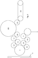
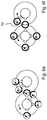
- the Figures 6a to 6f show examples of the container rotation on two consecutively arranged printing modules 2.
- the container is provided with position identifier 7, the area to be printed on the container 7 is marked in bold and identified with position number 8.
- the printheads 9 that move in this case are directed in particular perpendicularly to the outer wall of the container and point radially outward from the central axis of the modules 2. Only one print head 9 is drawn per module 2, however, a large number of print heads 9 are arranged on a module 2 at equidistant intervals, which preferably rotate continuously with the module 2 in the direction of rotation. Snapshots of a single container 7 with a single associated print head 9 can be seen in each figure.
- a container 7 is provided with a printed image only along part of its circumference, in Figure 6f with an all-round print.
- the rotation of the container 7 about its longitudinal axis is described below in relation to the relative movement from the container 7 to the rotating module 2.
- the end edge of the first partial print image faces the print head 9 belonging to the next module, so that this print head 9 begins its printing at the end edge of the first partial print image.
- the container 7 is now transported counterclockwise in the next module 2.4, but is rotated clockwise around its axis during printing. For realignment, the container 7 must be rotated from its receptacle (turntable) relative to the carousel by further rotation in the same direction by 180 °.
- the container 7 can be aligned more quickly in a rotational position in which the print head 9 of the next module is at an edge of the first partial print, if the starting edge of the first partial print image is aligned such that it faces the print head 9 of the next module 2.4 is facing.
- the container 7 can be aligned with the print heads of the following module 2.4 partly on the previous module 2.3 and partly on the following module 2.4 - depending on how much process time is available on the previous module 2.3.
- the printing in the following module 2.4 (right) only starts in the top left position (at half past eleven o'clock).
- the container 7 could therefore only be completely aligned in the module for the pressure in which it is to take place. This can be flexibly adjusted or even regulated, in particular via a control, depending on the print template and / or container.
- the container 7 is transferred in such a way that the opposite side of the container 7 faces the print head 9 of the next module 2.4 at the start and end edge 8a of the first partial print.
- There printing begins in the middle of the partial print image of the previous module 2.3.
- the two start and end edges of two partial print images are at a distance from one another. The distance is in particular greater than 5 °, in the case shown it is 180 °.
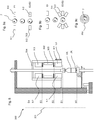
- FIG 7 the transfer situation of a container 7 between two modules 2.3 and 2.4 is shown. Only one half of a module is shown. The upper part of a module 2 is rotatably supported by means of ball swivel connector 88. On a center column 92 shown in half, the rotor 90 of a magnetic one is directly next to the rotary ball connection Direct drive attached. The stator 89 is fixed to the frame 93, which stands on a hall floor 93a. The rotatable column also provides the ink supply to print head 9 via a rotary distributor, not shown. This is connected via line 91 to a supply channel within the column 92.
- the print head 9 is mounted on the rotating part in the same way as the turntable 85, the drive for the turntable 87, a gripper 82 for the containers 7 and a centering head 83 for the containers 7.
- the centering head 83 can be adjusted in height by means of a magnetically acting linear drive with rotor 81 and stator 80.
- the turntable 85 and its drive 87 can be adjusted in height via a magnetically acting linear drive with rotor 86 and stator 87.
- the drive 87 is in particular also a servo drive, which interacts with a sensor 98 for the exact rotational position positioning of the containers 7.
- the sensor 98 is mounted outside the housing of the servo 87 and can thus interact with a part of the drive shaft which has a larger diameter. More increments for measuring the rotational position can be applied to the larger diameter.
- the increments are attached to the turntable 85 itself.
- the centering head 83 moves upwards and the turntable 85 downwards, so that the container 7 is only held by the gripper 82.
- the gripper 82 of the module 2.4 is then extended by means of a linear drive 84 and engages at another point along the longitudinal axis of the container 7 (not shown, preferably the areas above and below a support ring are alternately gripped) and pulls the container 7 towards the module 2.4 and positions the container 7 between the turntable 85 and the centering head 83 of the module 2.4.
- these two elements 83, 85 of the module 2.4 are brought towards one another for gripping and rotating the container 7 and the container 7 is either still aligned or printed directly via inkjet print head 9. It would also be possible that the gripper 82 of module 2.3 moves out and transfers the container to module 2.4. It would also be conceivable to move both grippers 82 out, so that the container 7 is transferred in the middle between the two modules 2.
- the containers can only be round, but also molded containers, which have a geometric element (for example a nose), by means of which they can be positioned in the individual modules, for example in that the centering head 83 or the rotary plate 85 or the clamp 82 have a counter element (for example a groove) into which the element can snap .
- a relative movement could be carried out, for example, between the rotary divider 85 and the container 7 until it engages.
- the drives 80, 81, 84, 86, 93, 87 involved could be force-controlled for this process.
- This example is also particularly suitable for a first alignment of the container 7 before or during the entry into the container equipment system 5.
- the gripper claws of the clamps 82 could also have their own drive.
- FIG 8 Another embodiment of a printing device 300 according to the invention can be seen.
- This has a carousel which rotates continuously about the vertical axis 301.
- the elements that are not provided with reference symbols (drives, sensors, etc.) work analogously to those in the Figure 7 .
- the bottles are inserted into the carousel between the lowering centering head and the stand plate in level E0 and clamped by these elements.
- the bottle is then raised to level E1, where the first partial printing is carried out with the print heads 9.1 and / or 9.4.
- the bottle is then transported past the annular shields 303 to UV curing 302 in level E2, where the first partial pressure is dried.
- the bottle is then transported to level E3, where the remaining colors for the print image are applied.
- the bottle On the levels E1, E2, E3, the bottle is rotated by at least the angle that the printed image occupies on the circumference of the bottle. If printing with two printheads 9.1 - 9.4 per printing level, the bottle can be moved briefly between the two steps into the UV curing level and then back into the same printing level E1, E3. It would also be conceivable to arrange all printheads in a ring in a printing plane and to use the methods described in the general part only between E2 and E1. E2 can also be arranged below or above all pressure levels. There may also be several levels for pinning the printing ink, for example between levels E3 and E4 and at level E2.
- the bottle can either be dispensed above all printheads 9 and UV stations 302 in level E4 or moved back for dispensing from the carousel in level E0.
- E4 would have the advantage that a larger process angle on the carousel could be used because an output almost (the Centering and the stand plate still need time to return to level E0) at the same circumferential position of the carousel as the entry can take place.
- a second pinning level between E3 and E4 can be present here.
- the bottle 7 can remain in one plane as long as it is rotated for this purpose. If the bottle 7 is to be printed over a height which is greater than the length Ld of the print head 9, the bottle can assume two different vertical positions one after the other in front of the same print head 9. Corresponding nozzles that are in a position that has already been printed on remain inactive in the second position.
- the bottle 7 performs a combined linear and rotary movement in relation to the print head 9 and is thus printed on the bottle 7 in a spiral.
- the bottle can also stand still for a short time to create a straight, horizontal top and bottom edge (OK, UK). If, for example, you start to print at the lower edge UK with all-round printing, the bottle 7 is first rotated in front of the print head 9 while it remains at a height. Thereafter, as the rotation continues around the longitudinal axis of the bottle 7, more and more nozzles of the print head 9 slowly switch on from top to bottom (along the print head height) while the bottle is moved upwards. When the top edge of OK is reached, the bottle remains vertical and only rotates once by 360 °.
- Figure 9a a variant of the successive rotary movements is shown, in which the pressure takes up about 90 ° of the bottle circumference.
- E1 the print was just completed by print head 9.4.
- the bottle is rotated through 90 ° in the same direction of rotation as before, so that it arrives at the printhead 9.2 or UV lamp 302 with the start edge of the first partial print image and can be further printed or dried directly .
- Figure 9c shows a UV tunnel with a ring-shaped curved UV lamp 302. Instead a plurality of individual lamps could also be arranged around the vertical container transport path of the curved lamp.
Landscapes
- Engineering & Computer Science (AREA)
- Manufacturing & Machinery (AREA)
- Health & Medical Sciences (AREA)
- General Health & Medical Sciences (AREA)
- Toxicology (AREA)
- Auxiliary Devices For And Details Of Packaging Control (AREA)
- Ink Jet (AREA)
- Coating Apparatus (AREA)
- Printing Methods (AREA)
- Details Of Rigid Or Semi-Rigid Containers (AREA)
Claims (4)
- Procédé d'impression de récipients, dans lequel un récipient constitué d'au moins deux modules rotatifs (2), sur lesquels sont disposées des têtes d'impression (9) tournant ensemble, est pourvu d'une image d'impression partielle pour chaque module(2), les récipients (7) étant transférés directement d'un module au suivant et les images d'impression partielles présentant chacune un bord de début et un bord de fin (8a) dans la direction périphérique du récipient (7),
caractérisé en ce que
après l'achèvement de la première image d'impression partielle, le récipient (7) reste aligné ou est réaligné par une rotation autour de son axe longitudinal de telle sorte que l'impression de la deuxième image d'impression partielle avec la tête d'impression (9) du module suivant (2) commence à une position périphérique du récipient (7) qui se trouve à une distance angulaire du bord final de la première image d'impression partielle,
il s'agit d'une impression complète,
le côté du conteneur (7) opposé au bord de début et de fin (8a) de la première impression partielle est tourné vers la tête d'impression (9) du module suivant (2),
la distance angulaire est égale à 180°, et
les têtes d'impression (9) se trouvent à l'intérieur du cercle primitif des deux modules d'impression (2) traversés par les conteneurs (7), les têtes d'impression (9) étant dirigées perpendiculairement à une paroi extérieure du conteneur et chacune d'elles étant dirigée radialement vers l'extérieur à partir d'un axe central des modules (2). - Procédé selon l'une des revendications précédentes, caractérisée en ce que dans le module suivant (2), l'impression est lancée au milieu de l'image d'impression partielle du module précédent.
- Procédé selon l'une des revendications précédentes, caractérisée en ce que, pour chaque module(2), l'impression est lancée au milieu de l'image d'impression partielle du module précédent (2), une pluralité de têtes d'impression (9) sont disposées à intervalles équidistants et tournent en continu avec le module (2) dans le sens de la rotation.
- Dispositif d'impression de récipients muni d'un dispositif de commande conçu pour mettre en oeuvre un procédé selon l'une des revendications 1 à 3 pour l'impression de récipients.
Applications Claiming Priority (3)
| Application Number | Priority Date | Filing Date | Title |
|---|---|---|---|
| DE102013001660 | 2013-01-31 | ||
| DE102013208061A DE102013208061A1 (de) | 2013-01-31 | 2013-05-02 | Vorrichtungen zum Bedrucken von Behältern und Verfahren dazu |
| EP14151853.0A EP2762317B1 (fr) | 2013-01-31 | 2014-01-21 | Dispositifs d'impression de récipients et procédé associé |
Related Parent Applications (2)
| Application Number | Title | Priority Date | Filing Date |
|---|---|---|---|
| EP14151853.0A Division-Into EP2762317B1 (fr) | 2013-01-31 | 2014-01-21 | Dispositifs d'impression de récipients et procédé associé |
| EP14151853.0A Division EP2762317B1 (fr) | 2013-01-31 | 2014-01-21 | Dispositifs d'impression de récipients et procédé associé |
Publications (2)
| Publication Number | Publication Date |
|---|---|
| EP3147129A1 EP3147129A1 (fr) | 2017-03-29 |
| EP3147129B1 true EP3147129B1 (fr) | 2020-07-01 |
Family
ID=48608140
Family Applications (2)
| Application Number | Title | Priority Date | Filing Date |
|---|---|---|---|
| EP16195559.6A Not-in-force EP3147129B1 (fr) | 2013-01-31 | 2014-01-21 | Procédé et dispositif d'impression de récipients |
| EP14151853.0A Active EP2762317B1 (fr) | 2013-01-31 | 2014-01-21 | Dispositifs d'impression de récipients et procédé associé |
Family Applications After (1)
| Application Number | Title | Priority Date | Filing Date |
|---|---|---|---|
| EP14151853.0A Active EP2762317B1 (fr) | 2013-01-31 | 2014-01-21 | Dispositifs d'impression de récipients et procédé associé |
Country Status (3)
| Country | Link |
|---|---|
| EP (2) | EP3147129B1 (fr) |
| CN (1) | CN103963485B (fr) |
| DE (1) | DE102013208061A1 (fr) |
Families Citing this family (25)
| Publication number | Priority date | Publication date | Assignee | Title |
|---|---|---|---|---|
| DE102013217665A1 (de) * | 2013-09-04 | 2015-03-05 | Krones Ag | Vorrichtung zum Bedrucken von Behältern |
| DE102013218399A1 (de) * | 2013-09-13 | 2015-03-19 | Krones Ag | Behälterbehandlungsanlage mit einem Ofen und einer Blasformvorrichtung mit Individual-Antrieb von Trägern für Preforms |
| WO2015036571A1 (fr) * | 2013-09-13 | 2015-03-19 | Till Gmbh | Machine d'impression d'objets en trois dimensions |
| DE102013110125A1 (de) * | 2013-09-13 | 2015-03-19 | Till Gmbh | Verfahren und Vorrichtung zur Oberflächenvorbehandlung eines dreidimensionalen Körpers |
| DE202013105244U1 (de) | 2013-11-20 | 2015-02-27 | Krones Ag | Direktdruckmaschine zum Bedrucken von Behältern |
| DE102014206730A1 (de) * | 2014-04-08 | 2015-10-08 | Krones Ag | Vorrichtung und Verfahren für den Tintenstrahldruck auf Behälter |
| DE102014108092A1 (de) * | 2014-06-10 | 2015-12-17 | Krones Ag | Direktdruckmaschine zum Bedrucken von Behältern |
| DE102014116987A1 (de) * | 2014-11-20 | 2016-05-25 | Krones Ag | Behälterbehandlungsanlage und Verfahren zum Behandeln von Behältern |
| DE102015100334A1 (de) | 2015-01-12 | 2016-07-14 | Khs Gmbh | Erfassungseinheit sowie Vorrichtung und Verfahren zur Bedruckung von Behältern |
| FR3034037B1 (fr) | 2015-03-25 | 2017-03-17 | Sidel Participations | Procede de fabrication d'un emballage comprenant un recipient imprime directement et traite par plasma |
| CN105459653B (zh) * | 2015-11-30 | 2018-03-09 | 广东星弛光电科技有限公司 | 一种手机面板的主体印刷工艺 |
| CN105774259A (zh) * | 2016-03-29 | 2016-07-20 | 苏州恩欧西智能科技有限公司 | 回转体产品的激光打标装置 |
| US20190174933A1 (en) | 2017-12-12 | 2019-06-13 | Gpcp Ip Holdings Llc | Food service cup dispensers, systems, and methods |
| US11472579B2 (en) | 2018-12-04 | 2022-10-18 | Gpcp Ip Holdings Llc | Film securing apparatus and method |
| US11752779B2 (en) | 2017-12-12 | 2023-09-12 | Gpcp Ip Holdings Llc | Food service cup dispensers, systems, and methods |
| WO2020072061A1 (fr) * | 2018-10-04 | 2020-04-09 | Vinventions Usa, Llc | Mandrin et dispositif de montage pour recevoir un objet cylindrique creux |
| DE102018212623A1 (de) * | 2018-07-27 | 2020-01-30 | Krones Ag | Verfahren zum Aufbringen einer Funktions-Schicht auf einen Behälter |
| US12077337B2 (en) | 2018-12-04 | 2024-09-03 | Yum Connect, LLC | Systems and methods for sealing a container |
| DE102018251784A1 (de) * | 2018-12-28 | 2020-07-02 | Krones Ag | Behälterbehandlungsanlage zum Behandeln von Behältern |
| DE102020120295A1 (de) * | 2020-07-31 | 2022-02-03 | Krones Aktiengesellschaft | Vorrichtung zum Ausstatten von Behältern |
| JP7658733B2 (ja) * | 2020-10-05 | 2025-04-08 | アルテミラ株式会社 | 印刷装置 |
| US11396191B1 (en) * | 2021-04-29 | 2022-07-26 | LSINC Corporation | Compact media decorator optimized for transparent and semi-transparent media |
| EP4155082B1 (fr) * | 2021-09-28 | 2025-08-27 | Hinterkopf GmbH | Dispositif d'impression numérique, procédé de fabrication et d'impression d'une pièce, système de fourniture des pièces imprimées |
| DE102021130583A1 (de) | 2021-11-23 | 2023-05-25 | Krones Aktiengesellschaft | Direktdrucksystem und Verfahren zum Betreiben eines Direktdrucksystems |
| DE102023103999A1 (de) * | 2023-02-17 | 2024-08-22 | Iwk Verpackungstechnik Gmbh | Tubenfüllmaschine und Verfahren zum Beschriften einer Tube in einer Tubenfüllmaschine |
Family Cites Families (16)
| Publication number | Priority date | Publication date | Assignee | Title |
|---|---|---|---|---|
| JP2001310454A (ja) * | 2000-04-27 | 2001-11-06 | Mitsubishi Electric Corp | インクジェットプリンタ |
| CH695555A5 (de) * | 2002-04-04 | 2006-06-30 | Faes Ag | Druckverfahren und Druckmaschine für dreidimensionale Druckobjekte. |
| ES2300912T3 (es) * | 2005-08-20 | 2008-06-16 | Hinterkopf Gmbh | Maquina para imprimir cuerpos huecos. |
| DE102007050490A1 (de) * | 2007-10-19 | 2009-04-23 | Khs Ag | Vorrichtung und Verfahren zum Bedrucken von Behältern |
| DE102007036752A1 (de) * | 2007-08-03 | 2009-02-05 | Khs Ag | Vorrichtung zum Bedrucken von Behältern |
| KR101153104B1 (ko) * | 2007-08-03 | 2012-06-04 | 케이에이치에스 게엠베하 | 용기에 인쇄를 하기 위한 장치 및 방법 |
| DE102008049241A1 (de) * | 2008-09-26 | 2010-04-08 | Khs Ag | Vorrichtung zum Aufbringen jeweils eines Mehrfachdrucks auf Packmittel |
| JP2010143200A (ja) * | 2008-12-22 | 2010-07-01 | Daiwa Can Co Ltd | 筒状体の外面に多色印刷を施す方法及びその装置 |
| DE102009013477B4 (de) | 2009-03-19 | 2012-01-12 | Khs Gmbh | Druckvorrichtung zum Bedrucken von Flaschen oder dergleichen Behältern |
| DE102009014321B4 (de) * | 2009-03-21 | 2011-07-21 | Walz GmbH & Co. KG, 89081 | Verfahren und Vorrichtung zum Bedrucken eines Gegenstands mit gekrümmter Mantelfläche |
| DE102010034780A1 (de) | 2010-08-18 | 2012-02-23 | Volker Till | Vorrichtung und Verfahren zum Bedrucken von Behältern |
| DE102011009395A1 (de) * | 2011-01-25 | 2012-07-26 | Krones Aktiengesellschaft | Vorrichtung und Verfahren zum Bedrucken von Behältern |
| JP5891602B2 (ja) * | 2011-04-28 | 2016-03-23 | 東洋製罐株式会社 | インクジェット印刷装置及びこれを用いたシームレス缶の印刷方法 |
| DE102012005046A1 (de) * | 2012-03-15 | 2013-09-19 | Till Gmbh | Verfahren zum Feststellen von Fehlern in der Ausrichtung von Druckbildern und zur Durchführung des Verfahrens eingerichtete Druckstation |
| DE102012209675A1 (de) * | 2012-06-08 | 2013-12-12 | Ball Packaging Europe Gmbh | Verfahren zum Bedrucken einer zylindrischen Druckoberfläche einer Getränkedose und bedruckte Getränkedose |
| DE102013003181A1 (de) * | 2013-02-25 | 2014-08-28 | Heidelberger Druckmaschinen Ag | Verfahren zum Erzeugen eines Druckbildes |
-
2013
- 2013-05-02 DE DE102013208061A patent/DE102013208061A1/de not_active Withdrawn
-
2014
- 2014-01-21 EP EP16195559.6A patent/EP3147129B1/fr not_active Not-in-force
- 2014-01-21 EP EP14151853.0A patent/EP2762317B1/fr active Active
- 2014-02-07 CN CN201410045052.0A patent/CN103963485B/zh not_active Expired - Fee Related
Non-Patent Citations (1)
| Title |
|---|
| None * |
Also Published As
| Publication number | Publication date |
|---|---|
| CN103963485A (zh) | 2014-08-06 |
| EP2762317B1 (fr) | 2019-03-13 |
| CN103963485B (zh) | 2016-08-24 |
| DE102013208061A1 (de) | 2013-07-04 |
| EP2762317A1 (fr) | 2014-08-06 |
| EP3147129A1 (fr) | 2017-03-29 |
Similar Documents
| Publication | Publication Date | Title |
|---|---|---|
| EP3147129B1 (fr) | Procédé et dispositif d'impression de récipients | |
| EP2611593B1 (fr) | Procédé pour produire et traiter des récipients | |
| DE102013208065A1 (de) | Rundläufermaschine zur Bedruckung von Behältern | |
| DE102010020958B4 (de) | Vorrichtung sowie Verfahren zum Bedrucken, insbesondere zum mehrfarbigen Bedrucken von Behältern | |
| EP2580061B1 (fr) | Dispositif de traitement d'emballages et unité de retenue et de centrage pour emballages | |
| DE102013214934A1 (de) | Vorrichtung und Verfahren zum Direktbedrucken von Behältern | |
| DE102014116405B4 (de) | Druckvorrichtung sowie Verfahren zur Bedruckung von Behältern | |
| EP2479036B1 (fr) | Dispositif et procédé destinés à l'impression de récipients | |
| DE102011009393A1 (de) | Vorrichtung und Verfahren zum Bedrucken von Behältern | |
| EP3337667A1 (fr) | Machine d'impression directe et procédé pour effectuer une impression directe sur des contenants | |
| DE102010034780A1 (de) | Vorrichtung und Verfahren zum Bedrucken von Behältern | |
| EP3678837B1 (fr) | Installation flexible de traitement de récipients | |
| DE102013213843A1 (de) | Behälterbehandlungsvorrichtung zur Bedruckung von Behältern | |
| EP2750895B1 (fr) | Dispositif de traitement d'emballages et segment d'impression à utiliser dans un tel dispositif | |
| DE102015215227A1 (de) | Behälterbehandlungsmaschine und Verfahren zur Bedruckung von Behältern | |
| DE102015215295A1 (de) | Druckmaschine für Behälter und Verfahren zum Bedrucken von Behältern | |
| DE102018000405A1 (de) | Vorrichtung und Verfahren zur Herstellung von Gebinden | |
| DE102013213846A1 (de) | Behälterbehandlungsvorrichtung zur Etikettierung und/oder Bedruckung von Behältern | |
| WO2022023167A1 (fr) | Dispositif de gaufrage ou d'étiquetage de récipients | |
| DE202013004057U1 (de) | Behälterausstattungsanlage | |
| EP3157753B1 (fr) | Procédé et dispositif d'impression de corps creux | |
| DE102013015193A1 (de) | Behälteraustattungsanlage | |
| DE202013004037U1 (de) | Behälterausstattungsanlage | |
| DE102016202551A1 (de) | Verfahren, Druckkopf und Maschine zum Bedrucken eines Behälters | |
| DE202008018588U1 (de) | Streckblasmaschine mit Druckeinheit |
Legal Events
| Date | Code | Title | Description |
|---|---|---|---|
| PUAI | Public reference made under article 153(3) epc to a published international application that has entered the european phase |
Free format text: ORIGINAL CODE: 0009012 |
|
| STAA | Information on the status of an ep patent application or granted ep patent |
Free format text: STATUS: THE APPLICATION HAS BEEN PUBLISHED |
|
| AC | Divisional application: reference to earlier application |
Ref document number: 2762317 Country of ref document: EP Kind code of ref document: P |
|
| AK | Designated contracting states |
Kind code of ref document: A1 Designated state(s): AL AT BE BG CH CY CZ DE DK EE ES FI FR GB GR HR HU IE IS IT LI LT LU LV MC MK MT NL NO PL PT RO RS SE SI SK SM TR |
|
| STAA | Information on the status of an ep patent application or granted ep patent |
Free format text: STATUS: REQUEST FOR EXAMINATION WAS MADE |
|
| 17P | Request for examination filed |
Effective date: 20170928 |
|
| RBV | Designated contracting states (corrected) |
Designated state(s): AL AT BE BG CH CY CZ DE DK EE ES FI FR GB GR HR HU IE IS IT LI LT LU LV MC MK MT NL NO PL PT RO RS SE SI SK SM TR |
|
| STAA | Information on the status of an ep patent application or granted ep patent |
Free format text: STATUS: EXAMINATION IS IN PROGRESS |
|
| 17Q | First examination report despatched |
Effective date: 20190718 |
|
| GRAP | Despatch of communication of intention to grant a patent |
Free format text: ORIGINAL CODE: EPIDOSNIGR1 |
|
| STAA | Information on the status of an ep patent application or granted ep patent |
Free format text: STATUS: GRANT OF PATENT IS INTENDED |
|
| RIC1 | Information provided on ipc code assigned before grant |
Ipc: B41M 5/00 20060101ALI20200221BHEP Ipc: B41J 11/00 20060101ALI20200221BHEP Ipc: B41J 3/407 20060101AFI20200221BHEP Ipc: B41M 1/18 20060101ALI20200221BHEP Ipc: B41M 1/40 20060101ALI20200221BHEP |
|
| INTG | Intention to grant announced |
Effective date: 20200325 |
|
| GRAS | Grant fee paid |
Free format text: ORIGINAL CODE: EPIDOSNIGR3 |
|
| GRAA | (expected) grant |
Free format text: ORIGINAL CODE: 0009210 |
|
| STAA | Information on the status of an ep patent application or granted ep patent |
Free format text: STATUS: THE PATENT HAS BEEN GRANTED |
|
| AC | Divisional application: reference to earlier application |
Ref document number: 2762317 Country of ref document: EP Kind code of ref document: P |
|
| AK | Designated contracting states |
Kind code of ref document: B1 Designated state(s): AL AT BE BG CH CY CZ DE DK EE ES FI FR GB GR HR HU IE IS IT LI LT LU LV MC MK MT NL NO PL PT RO RS SE SI SK SM TR |
|
| REG | Reference to a national code |
Ref country code: AT Ref legal event code: REF Ref document number: 1285807 Country of ref document: AT Kind code of ref document: T Effective date: 20200715 Ref country code: CH Ref legal event code: EP |
|
| REG | Reference to a national code |
Ref country code: IE Ref legal event code: FG4D Free format text: LANGUAGE OF EP DOCUMENT: GERMAN |
|
| REG | Reference to a national code |
Ref country code: DE Ref legal event code: R096 Ref document number: 502014014401 Country of ref document: DE |
|
| REG | Reference to a national code |
Ref country code: LT Ref legal event code: MG4D |
|
| PG25 | Lapsed in a contracting state [announced via postgrant information from national office to epo] |
Ref country code: BG Free format text: LAPSE BECAUSE OF FAILURE TO SUBMIT A TRANSLATION OF THE DESCRIPTION OR TO PAY THE FEE WITHIN THE PRESCRIBED TIME-LIMIT Effective date: 20201001 |
|
| REG | Reference to a national code |
Ref country code: NL Ref legal event code: MP Effective date: 20200701 |
|
| PG25 | Lapsed in a contracting state [announced via postgrant information from national office to epo] |
Ref country code: PT Free format text: LAPSE BECAUSE OF FAILURE TO SUBMIT A TRANSLATION OF THE DESCRIPTION OR TO PAY THE FEE WITHIN THE PRESCRIBED TIME-LIMIT Effective date: 20201102 Ref country code: CZ Free format text: LAPSE BECAUSE OF FAILURE TO SUBMIT A TRANSLATION OF THE DESCRIPTION OR TO PAY THE FEE WITHIN THE PRESCRIBED TIME-LIMIT Effective date: 20200701 Ref country code: ES Free format text: LAPSE BECAUSE OF FAILURE TO SUBMIT A TRANSLATION OF THE DESCRIPTION OR TO PAY THE FEE WITHIN THE PRESCRIBED TIME-LIMIT Effective date: 20200701 Ref country code: LT Free format text: LAPSE BECAUSE OF FAILURE TO SUBMIT A TRANSLATION OF THE DESCRIPTION OR TO PAY THE FEE WITHIN THE PRESCRIBED TIME-LIMIT Effective date: 20200701 Ref country code: HR Free format text: LAPSE BECAUSE OF FAILURE TO SUBMIT A TRANSLATION OF THE DESCRIPTION OR TO PAY THE FEE WITHIN THE PRESCRIBED TIME-LIMIT Effective date: 20200701 Ref country code: SE Free format text: LAPSE BECAUSE OF FAILURE TO SUBMIT A TRANSLATION OF THE DESCRIPTION OR TO PAY THE FEE WITHIN THE PRESCRIBED TIME-LIMIT Effective date: 20200701 Ref country code: GR Free format text: LAPSE BECAUSE OF FAILURE TO SUBMIT A TRANSLATION OF THE DESCRIPTION OR TO PAY THE FEE WITHIN THE PRESCRIBED TIME-LIMIT Effective date: 20201002 Ref country code: FI Free format text: LAPSE BECAUSE OF FAILURE TO SUBMIT A TRANSLATION OF THE DESCRIPTION OR TO PAY THE FEE WITHIN THE PRESCRIBED TIME-LIMIT Effective date: 20200701 Ref country code: NO Free format text: LAPSE BECAUSE OF FAILURE TO SUBMIT A TRANSLATION OF THE DESCRIPTION OR TO PAY THE FEE WITHIN THE PRESCRIBED TIME-LIMIT Effective date: 20201001 |
|
| PG25 | Lapsed in a contracting state [announced via postgrant information from national office to epo] |
Ref country code: IS Free format text: LAPSE BECAUSE OF FAILURE TO SUBMIT A TRANSLATION OF THE DESCRIPTION OR TO PAY THE FEE WITHIN THE PRESCRIBED TIME-LIMIT Effective date: 20201101 Ref country code: RS Free format text: LAPSE BECAUSE OF FAILURE TO SUBMIT A TRANSLATION OF THE DESCRIPTION OR TO PAY THE FEE WITHIN THE PRESCRIBED TIME-LIMIT Effective date: 20200701 Ref country code: LV Free format text: LAPSE BECAUSE OF FAILURE TO SUBMIT A TRANSLATION OF THE DESCRIPTION OR TO PAY THE FEE WITHIN THE PRESCRIBED TIME-LIMIT Effective date: 20200701 Ref country code: PL Free format text: LAPSE BECAUSE OF FAILURE TO SUBMIT A TRANSLATION OF THE DESCRIPTION OR TO PAY THE FEE WITHIN THE PRESCRIBED TIME-LIMIT Effective date: 20200701 |
|
| PG25 | Lapsed in a contracting state [announced via postgrant information from national office to epo] |
Ref country code: NL Free format text: LAPSE BECAUSE OF FAILURE TO SUBMIT A TRANSLATION OF THE DESCRIPTION OR TO PAY THE FEE WITHIN THE PRESCRIBED TIME-LIMIT Effective date: 20200701 |
|
| REG | Reference to a national code |
Ref country code: DE Ref legal event code: R097 Ref document number: 502014014401 Country of ref document: DE |
|
| PG25 | Lapsed in a contracting state [announced via postgrant information from national office to epo] |
Ref country code: EE Free format text: LAPSE BECAUSE OF FAILURE TO SUBMIT A TRANSLATION OF THE DESCRIPTION OR TO PAY THE FEE WITHIN THE PRESCRIBED TIME-LIMIT Effective date: 20200701 Ref country code: DK Free format text: LAPSE BECAUSE OF FAILURE TO SUBMIT A TRANSLATION OF THE DESCRIPTION OR TO PAY THE FEE WITHIN THE PRESCRIBED TIME-LIMIT Effective date: 20200701 Ref country code: RO Free format text: LAPSE BECAUSE OF FAILURE TO SUBMIT A TRANSLATION OF THE DESCRIPTION OR TO PAY THE FEE WITHIN THE PRESCRIBED TIME-LIMIT Effective date: 20200701 Ref country code: SM Free format text: LAPSE BECAUSE OF FAILURE TO SUBMIT A TRANSLATION OF THE DESCRIPTION OR TO PAY THE FEE WITHIN THE PRESCRIBED TIME-LIMIT Effective date: 20200701 |
|
| PLBE | No opposition filed within time limit |
Free format text: ORIGINAL CODE: 0009261 |
|
| STAA | Information on the status of an ep patent application or granted ep patent |
Free format text: STATUS: NO OPPOSITION FILED WITHIN TIME LIMIT |
|
| PG25 | Lapsed in a contracting state [announced via postgrant information from national office to epo] |
Ref country code: AL Free format text: LAPSE BECAUSE OF FAILURE TO SUBMIT A TRANSLATION OF THE DESCRIPTION OR TO PAY THE FEE WITHIN THE PRESCRIBED TIME-LIMIT Effective date: 20200701 |
|
| 26N | No opposition filed |
Effective date: 20210406 |
|
| PG25 | Lapsed in a contracting state [announced via postgrant information from national office to epo] |
Ref country code: SK Free format text: LAPSE BECAUSE OF FAILURE TO SUBMIT A TRANSLATION OF THE DESCRIPTION OR TO PAY THE FEE WITHIN THE PRESCRIBED TIME-LIMIT Effective date: 20200701 |
|
| PG25 | Lapsed in a contracting state [announced via postgrant information from national office to epo] |
Ref country code: MC Free format text: LAPSE BECAUSE OF FAILURE TO SUBMIT A TRANSLATION OF THE DESCRIPTION OR TO PAY THE FEE WITHIN THE PRESCRIBED TIME-LIMIT Effective date: 20200701 Ref country code: SI Free format text: LAPSE BECAUSE OF FAILURE TO SUBMIT A TRANSLATION OF THE DESCRIPTION OR TO PAY THE FEE WITHIN THE PRESCRIBED TIME-LIMIT Effective date: 20200701 |
|
| REG | Reference to a national code |
Ref country code: CH Ref legal event code: PL |
|
| GBPC | Gb: european patent ceased through non-payment of renewal fee |
Effective date: 20210121 |
|
| PG25 | Lapsed in a contracting state [announced via postgrant information from national office to epo] |
Ref country code: LU Free format text: LAPSE BECAUSE OF NON-PAYMENT OF DUE FEES Effective date: 20210121 |
|
| PG25 | Lapsed in a contracting state [announced via postgrant information from national office to epo] |
Ref country code: LI Free format text: LAPSE BECAUSE OF NON-PAYMENT OF DUE FEES Effective date: 20210131 Ref country code: GB Free format text: LAPSE BECAUSE OF NON-PAYMENT OF DUE FEES Effective date: 20210121 Ref country code: CH Free format text: LAPSE BECAUSE OF NON-PAYMENT OF DUE FEES Effective date: 20210131 |
|
| PG25 | Lapsed in a contracting state [announced via postgrant information from national office to epo] |
Ref country code: IE Free format text: LAPSE BECAUSE OF NON-PAYMENT OF DUE FEES Effective date: 20210121 |
|
| REG | Reference to a national code |
Ref country code: AT Ref legal event code: MM01 Ref document number: 1285807 Country of ref document: AT Kind code of ref document: T Effective date: 20210121 |
|
| PG25 | Lapsed in a contracting state [announced via postgrant information from national office to epo] |
Ref country code: AT Free format text: LAPSE BECAUSE OF NON-PAYMENT OF DUE FEES Effective date: 20210121 |
|
| PG25 | Lapsed in a contracting state [announced via postgrant information from national office to epo] |
Ref country code: IS Free format text: LAPSE BECAUSE OF FAILURE TO SUBMIT A TRANSLATION OF THE DESCRIPTION OR TO PAY THE FEE WITHIN THE PRESCRIBED TIME-LIMIT Effective date: 20201101 |
|
| PG25 | Lapsed in a contracting state [announced via postgrant information from national office to epo] |
Ref country code: HU Free format text: LAPSE BECAUSE OF FAILURE TO SUBMIT A TRANSLATION OF THE DESCRIPTION OR TO PAY THE FEE WITHIN THE PRESCRIBED TIME-LIMIT; INVALID AB INITIO Effective date: 20140121 |
|
| P01 | Opt-out of the competence of the unified patent court (upc) registered |
Effective date: 20230523 |
|
| PG25 | Lapsed in a contracting state [announced via postgrant information from national office to epo] |
Ref country code: CY Free format text: LAPSE BECAUSE OF FAILURE TO SUBMIT A TRANSLATION OF THE DESCRIPTION OR TO PAY THE FEE WITHIN THE PRESCRIBED TIME-LIMIT Effective date: 20200701 |
|
| PGFP | Annual fee paid to national office [announced via postgrant information from national office to epo] |
Ref country code: FR Payment date: 20231212 Year of fee payment: 11 |
|
| PGFP | Annual fee paid to national office [announced via postgrant information from national office to epo] |
Ref country code: BE Payment date: 20231219 Year of fee payment: 11 |
|
| PG25 | Lapsed in a contracting state [announced via postgrant information from national office to epo] |
Ref country code: MK Free format text: LAPSE BECAUSE OF FAILURE TO SUBMIT A TRANSLATION OF THE DESCRIPTION OR TO PAY THE FEE WITHIN THE PRESCRIBED TIME-LIMIT Effective date: 20200701 |
|
| PGFP | Annual fee paid to national office [announced via postgrant information from national office to epo] |
Ref country code: DE Payment date: 20231205 Year of fee payment: 11 |
|
| PGFP | Annual fee paid to national office [announced via postgrant information from national office to epo] |
Ref country code: IT Payment date: 20231212 Year of fee payment: 11 |
|
| PG25 | Lapsed in a contracting state [announced via postgrant information from national office to epo] |
Ref country code: TR Free format text: LAPSE BECAUSE OF FAILURE TO SUBMIT A TRANSLATION OF THE DESCRIPTION OR TO PAY THE FEE WITHIN THE PRESCRIBED TIME-LIMIT Effective date: 20200701 |
|
| PG25 | Lapsed in a contracting state [announced via postgrant information from national office to epo] |
Ref country code: MT Free format text: LAPSE BECAUSE OF FAILURE TO SUBMIT A TRANSLATION OF THE DESCRIPTION OR TO PAY THE FEE WITHIN THE PRESCRIBED TIME-LIMIT Effective date: 20200701 |
|
| REG | Reference to a national code |
Ref country code: DE Ref legal event code: R119 Ref document number: 502014014401 Country of ref document: DE |
|
| PG25 | Lapsed in a contracting state [announced via postgrant information from national office to epo] |
Ref country code: DE Free format text: LAPSE BECAUSE OF NON-PAYMENT OF DUE FEES Effective date: 20250801 |
|
| PG25 | Lapsed in a contracting state [announced via postgrant information from national office to epo] |
Ref country code: BE Free format text: LAPSE BECAUSE OF NON-PAYMENT OF DUE FEES Effective date: 20250131 |
|
| PG25 | Lapsed in a contracting state [announced via postgrant information from national office to epo] |
Ref country code: FR Free format text: LAPSE BECAUSE OF NON-PAYMENT OF DUE FEES Effective date: 20250131 |
|
| REG | Reference to a national code |
Ref country code: BE Ref legal event code: MM Effective date: 20250131 |
|
| PG25 | Lapsed in a contracting state [announced via postgrant information from national office to epo] |
Ref country code: IT Free format text: LAPSE BECAUSE OF NON-PAYMENT OF DUE FEES Effective date: 20250121 |