EP3147204A1 - Tragflächenprofil für niedrige geschwindigkeit für verbesserte aerodynamische leistung von uavs - Google Patents
Tragflächenprofil für niedrige geschwindigkeit für verbesserte aerodynamische leistung von uavs Download PDFInfo
- Publication number
- EP3147204A1 EP3147204A1 EP16176649.8A EP16176649A EP3147204A1 EP 3147204 A1 EP3147204 A1 EP 3147204A1 EP 16176649 A EP16176649 A EP 16176649A EP 3147204 A1 EP3147204 A1 EP 3147204A1
- Authority
- EP
- European Patent Office
- Prior art keywords
- airfoil
- chord
- subsection
- uav
- degrees
- Prior art date
- Legal status (The legal status is an assumption and is not a legal conclusion. Google has not performed a legal analysis and makes no representation as to the accuracy of the status listed.)
- Granted
Links
Images




Classifications
-
- B—PERFORMING OPERATIONS; TRANSPORTING
- B64—AIRCRAFT; AVIATION; COSMONAUTICS
- B64C—AEROPLANES; HELICOPTERS
- B64C3/00—Wings
- B64C3/10—Shape of wings
-
- B—PERFORMING OPERATIONS; TRANSPORTING
- B64—AIRCRAFT; AVIATION; COSMONAUTICS
- B64C—AEROPLANES; HELICOPTERS
- B64C3/00—Wings
- B64C3/10—Shape of wings
- B64C3/14—Aerofoil profile
-
- B—PERFORMING OPERATIONS; TRANSPORTING
- B64—AIRCRAFT; AVIATION; COSMONAUTICS
- B64C—AEROPLANES; HELICOPTERS
- B64C3/00—Wings
- B64C3/34—Tanks constructed integrally with wings, e.g. for fuel or water
-
- B—PERFORMING OPERATIONS; TRANSPORTING
- B64—AIRCRAFT; AVIATION; COSMONAUTICS
- B64U—UNMANNED AERIAL VEHICLES [UAV]; EQUIPMENT THEREFOR
- B64U10/00—Type of UAV
- B64U10/25—Fixed-wing aircraft
-
- B—PERFORMING OPERATIONS; TRANSPORTING
- B64—AIRCRAFT; AVIATION; COSMONAUTICS
- B64U—UNMANNED AERIAL VEHICLES [UAV]; EQUIPMENT THEREFOR
- B64U20/00—Constructional aspects of UAVs
- B64U20/70—Constructional aspects of the UAV body
-
- B—PERFORMING OPERATIONS; TRANSPORTING
- B64—AIRCRAFT; AVIATION; COSMONAUTICS
- B64U—UNMANNED AERIAL VEHICLES [UAV]; EQUIPMENT THEREFOR
- B64U30/00—Means for producing lift; Empennages; Arrangements thereof
- B64U30/10—Wings
- B64U30/12—Variable or detachable wings, e.g. wings with adjustable sweep
-
- B—PERFORMING OPERATIONS; TRANSPORTING
- B64—AIRCRAFT; AVIATION; COSMONAUTICS
- B64C—AEROPLANES; HELICOPTERS
- B64C3/00—Wings
- B64C3/10—Shape of wings
- B64C3/14—Aerofoil profile
- B64C2003/143—Aerofoil profile comprising interior channels
-
- B—PERFORMING OPERATIONS; TRANSPORTING
- B64—AIRCRAFT; AVIATION; COSMONAUTICS
- B64C—AEROPLANES; HELICOPTERS
- B64C3/00—Wings
- B64C3/10—Shape of wings
- B64C3/14—Aerofoil profile
- B64C2003/146—Aerofoil profile comprising leading edges of particular shape
-
- B—PERFORMING OPERATIONS; TRANSPORTING
- B64—AIRCRAFT; AVIATION; COSMONAUTICS
- B64C—AEROPLANES; HELICOPTERS
- B64C3/00—Wings
- B64C3/10—Shape of wings
- B64C3/14—Aerofoil profile
- B64C2003/147—Aerofoil profile comprising trailing edges of particular shape
-
- Y—GENERAL TAGGING OF NEW TECHNOLOGICAL DEVELOPMENTS; GENERAL TAGGING OF CROSS-SECTIONAL TECHNOLOGIES SPANNING OVER SEVERAL SECTIONS OF THE IPC; TECHNICAL SUBJECTS COVERED BY FORMER USPC CROSS-REFERENCE ART COLLECTIONS [XRACs] AND DIGESTS
- Y02—TECHNOLOGIES OR APPLICATIONS FOR MITIGATION OR ADAPTATION AGAINST CLIMATE CHANGE
- Y02T—CLIMATE CHANGE MITIGATION TECHNOLOGIES RELATED TO TRANSPORTATION
- Y02T50/00—Aeronautics or air transport
- Y02T50/10—Drag reduction
Definitions
- This disclosure relates generally to airfoils used in aircraft and more particularly to an airfoil design suited for Unmanned Aerial Vehicles.
- Some aircraft designs particularly unmanned aerial vehicles, use complex wing or airfoil shapes for improved low-speed performance. These airfoils often exhibit severe stall properties that prevent the aircraft from operating over a full range of conditions. Further, these complex shapes are difficult to manufacture, have limited internal volume, and may not be conducive to attaching external components, such as trailing edge flaps.
- FIG. 1 A side view of a prior art airfoil 10 is illustrated in Fig. 1 .
- the airfoil 10 has an upper surface 12 and a lower surface 14.
- the airfoil 10 is characterized by a complex curvature that increases both structural weight and manufacturing complexity.
- the thin trailing edge 16 makes it difficult or impossible to integrate trailing edge flaps.
- the thin profile and high camber reduces interior volume and correspondingly reduces fuel storage capacity. The high camber also increases the difficulty of including the structural components necessary for integrating a deployable (folding) wing into an airframe.
- an airfoil configured for low speed performance in an unmanned aerial vehicle includes an upper surface having an upper surface portion with a top local surface angle magnitude of less than 5 degrees at a subsection of a chord and a lower surface having a lower surface portion with a bottom local surface angle magnitude of less than 5 degrees at the subsection of the chord.
- the chord is defined by a line starting at a leading edge of the airfoil and extending to a trailing edge of the airfoil.
- an unmanned aerial vehicle in another embodiment, includes a fuselage, a propulsion unit mechanically coupled to the fuselage, and an airfoil coupled to the fuselage.
- the airfoil includes an upper surface having an upper surface portion having a top local surface angle less than 5 degrees at a subsection of a chord and a lower surface having a lower surface portion having a bottom local surface angle less than 5 degrees at the subsection of the chord.
- the chord is defined by a line starting at a leading edge of the airfoil and extending to a trailing edge of the airfoil.
- a method of assembling an unmanned aerial vehicle includes providing a fuselage, attaching a propulsion unit to the fuselage, and attaching an airfoil to the fuselage.
- the airfoil has an upper surface that includes an upper surface portion having a top local surface angle less than 5 degrees at a subsection of a chord and a lower surface that includes a lower surface portion having a bottom local surface angle less than 5 degrees at the subsection of the chord.
- the chord is defined by a line starting at a leading edge of the airfoil and extending to a trailing edge of the airfoil.
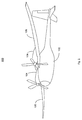
- Fig. 2 is a perspective view of an unmanned aerial vehicle (UAV) 100.
- the UAV 100 includes a fuselage 102 and a propulsion unit 104, that may be directly or indirectly coupled to the fuselage 102. That is, in some embodiments, the propulsion unit 104 may be coupled to a wing or airfoil 106, or in other embodiments, the propulsion unit 104 may be coupled directly to the fuselage 102. In other embodiments, multiple propulsion units 104 may be coupled to the airfoil 106.
- the airfoil 106 is configured to improve the performance of the UAV 100 with respect to lift at zero angle of attack and to reduce drag on the lower surface of the airfoil 106 as discussed in more detail below.
- Fig. 3 is a cross section of an airfoil 106 in accordance with the current disclosure.
- the airfoil 106 includes an upper surface 120 and a lower surface 122.
- a leading edge 124 is driven into oncoming air by movement of the UAV 100.
- the trailing edge 126 is where the upper surface 120 and the lower surface 122 meet opposite the leading edge 124.
- the chord is defined as a straight line between the leading edge 124 and the trailing edge 126. It is common to normalize an airfoil front-to-back distance to the length of the chord, as is done in Figs. 4 and 5 below. This is noted as x/c, where x is the current point and c is the length of chord. That is, the center point of the chord is defined as an x/c of 0.5 or 50%.
- a mean camber line 130 is defined as the vertical midpoint between the upper surface 120 and the lower surface 122.
- the airfoil camber 132 is defined as the maximum distance from the chord 128 to the mean camber line 130.
- the local surface angle is defined as the angle of a line tangent to the point.
- a first local surface angle 134 is positive while a second local surface angle 136 is negative. Local surface angles are discussed more below.
- Fig. 4 illustrates an airfoil 140 which is a variation of the airfoil 106 of Fig. 3 .
- the airfoil 140 is in two sections, a main section 142 and a flap 144.
- the flap 144 may be attached to an aft end 143 of the main section 142 to complete the airfoil 140.
- the main section 142 and the fully retracted flap 144 generally match the shape of the airfoil 106 of Fig. 3 .
- Both airfoils 106 and 140 may also include a tank 146.
- the tank 146 may be created by simply sealing the inner surfaces of the airfoil 106, 140 so that fuel or other liquid can be pumped directly into an interior space 147 of the airfoil 106, 140.
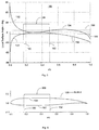
- Fig. 5 is a chart 150 showing a local surface angle 152 for the upper surface 120 of the airfoil 106 and a local surface angle for the lower surface 122 of the airfoil 106.
- the upper surface local surface angle starts out highly positive as the upper surface 120 rises quickly from the leading edge 124 and begins to decrease as the upper surface 120 flattens.
- the local surface angle 152 falls to less than 5 degrees (line 156) at a distance divided by chord length (x/c) of a little less than 20%, indicated by line 160.
- the lower surface 122 has a high negative local surface angle 154 from the leading edge 124 and falls to less than -5% at a distance from the leading edge 124 of approximately 20% of x/c. Both the upper surface 120 and lower surface 122 local surface angles have a magnitude (absolute value) of less than about 5% until the local surface angle of the lower surface 122 exceeds 5% at a little less than 50% of x/c, indicated by line 162. Both the upper surface 120 and the lower surface 122 have overlapping sections with local surface angle magnitudes of less than 5 degrees at a subsection 168 of the chord from about 27% of the chord to about 38% of the chord, or more.
- the subsection 168 of chord span where both upper and lower surfaces 120 and 122 have local surface angles of less than 5 degrees is from 30% to 35% of the chord, measured from the leading edge 124.
- the subsection of chord span, where this overlap occurs may vary but is generally in the front half of the airfoil and generally covers 5% or more of the airfoil chord length.
- Fig. 6 illustrates one embodiment of the airfoil 106 showing the subsection 168 described above between lines 160 and 162. That is, the subsection 168 is that portion of the airfoil 106 with both the upper surface portion 164 and the lower surface portion 166 that have local surface angles with a magnitude of less than 5 degrees. In the illustrated embodiment, the subsection 168 has both the upper surface portion 164 and lower surface portion 166 have local surface angles less than 5 degrees occurs between lines 160 and 162.
- airfoil 106 or airfoil 140 distinguish their design from conventional UAV airfoils which are thinner top-to-bottom and have very high camber, making them difficult to manufacture and having little internal volume.
- the airfoils 106 and 140 have a bulbous front.
- the airfoils 106, 140 exhibit a "virtual camber" by way of the top surface height above the leading edge 124.
- the airfoil 106 achieves maximum lift/drag ratios at lower angle-of-attack compared to other current low speed airfoils.
- the resulting wide margin of angle of attack between maximum lift-to-drag and stall angle-of-attack means the airfoil 106 can operate at its maximum potential even in the presence of atmospheric turbulence compared to other high performance low-speed airfoils.
- the low angle portion 166 of the lower surface reduces drag and improves flight efficiency.
- the lower surface 122 has less than 10% of the drag attributable to the upper surface 120.
- the increased height of the wing increases interior volume that accommodates wing tanks in general and fuel storage in particular.
- the increased height between upper surface 120 and lower surface 122 also allows separate flaps 144 to be attached to the main section 142 creating the possibility of adjustable flaps or more easily changed aft profiles for different operating conditions.
- the increased height makes it easier to moveably attach the airfoil 106 to the fuselage 102, for example, when folding airfoils are advantageous for storage and transportation of the UAV 100.
- Fig. 7 is a flowchart of a method 200 of assembling an unmanned aerial vehicle (UAV) 100.
- UAV unmanned aerial vehicle
- a fuselage 102 is provided.
- a propulsion unit 104 may be attached to the fuselage 102.
- the propulsion unit 104 may be attached directly to the fuselage 102, as is seen in most single engine UAV's, or two or more the propulsion units 104 may be attached to airfoils 106 that in turn are attached to the fuselage 102 as shown in Fig. 2 .
- an airfoil 106 may be attached to the fuselage 102.
- the airfoil 106 has an upper surface 120 that includes an upper surface portion 164 having a top local surface angle magnitude less than 5 degrees at a subsection 168 of a chord 128, wherein the chord 128 is defined by a line starting at a leading edge 124 of the airfoil 106 and extending to a trailing edge 126 of the airfoil 106, and a lower surface 122 that includes a lower surface portion 166 having a bottom local surface angle magnitude less than 5 degrees at the subsection of the chord.
- the both the upper surface 120 and the lower surface 122 have a local surface angle between -5 degrees and + 5 degrees.
- the airfoil 106 has a maximum thickness extending from about 20% to about 40% of the chord from a leading edge 124 of the airfoil. The maximum thickness in this area of the airfoil 106 creates a 'virtual camber' that increases lift at zero angle of attack.
- the airfoil subsection 168 of the chord 128 includes a point 30% from a leading edge 124 of the airfoil 106 measured along the chord 128.
- a flap assembly may be attached to an aft end 143 of a main section 142 of an airfoil 140.
- Fuel storage may be provided in either airfoil 106 or airfoil 140 at block 208 using a tank 146 or simply sealing an interior space of the airfoil 106 or a main section 142 of airfoil 140.
- UAVs 100 or conventional aircraft that use airfoils 106, 140 with at least a major portion having the shape described above exhibit improved stall characteristics, less lower surface drag, and have greater interior storage compared to conventional low-speed airfoil designs.
- airfoils 106, 140 in accordance with this design are easier to manufacture because they have fewer and lower radius curves compared to previously used wings. For example, some prior art airfoils use a reflex camber. An airfoil in accordance with the current description has a non-reflex camber.
Landscapes
- Engineering & Computer Science (AREA)
- Aviation & Aerospace Engineering (AREA)
- Mechanical Engineering (AREA)
- Remote Sensing (AREA)
- Structures Of Non-Positive Displacement Pumps (AREA)
Priority Applications (1)
| Application Number | Priority Date | Filing Date | Title |
|---|---|---|---|
| EP20172191.7A EP3705395A1 (de) | 2015-09-25 | 2016-06-28 | Tragflächenprofil für niedrige geschwindigkeit für verbesserte aerodynamische leistung von uavs |
Applications Claiming Priority (1)
| Application Number | Priority Date | Filing Date | Title |
|---|---|---|---|
| US14/865,851 US9868525B2 (en) | 2015-09-25 | 2015-09-25 | Low speed airfoil design for aerodynamic improved performance of UAVs |
Related Child Applications (2)
| Application Number | Title | Priority Date | Filing Date |
|---|---|---|---|
| EP20172191.7A Division EP3705395A1 (de) | 2015-09-25 | 2016-06-28 | Tragflächenprofil für niedrige geschwindigkeit für verbesserte aerodynamische leistung von uavs |
| EP20172191.7A Division-Into EP3705395A1 (de) | 2015-09-25 | 2016-06-28 | Tragflächenprofil für niedrige geschwindigkeit für verbesserte aerodynamische leistung von uavs |
Publications (2)
| Publication Number | Publication Date |
|---|---|
| EP3147204A1 true EP3147204A1 (de) | 2017-03-29 |
| EP3147204B1 EP3147204B1 (de) | 2020-08-19 |
Family
ID=56289370
Family Applications (2)
| Application Number | Title | Priority Date | Filing Date |
|---|---|---|---|
| EP16176649.8A Active EP3147204B1 (de) | 2015-09-25 | 2016-06-28 | Tragflächenprofil für niedrige geschwindigkeit für verbesserte aerodynamische leistung von uavs |
| EP20172191.7A Ceased EP3705395A1 (de) | 2015-09-25 | 2016-06-28 | Tragflächenprofil für niedrige geschwindigkeit für verbesserte aerodynamische leistung von uavs |
Family Applications After (1)
| Application Number | Title | Priority Date | Filing Date |
|---|---|---|---|
| EP20172191.7A Ceased EP3705395A1 (de) | 2015-09-25 | 2016-06-28 | Tragflächenprofil für niedrige geschwindigkeit für verbesserte aerodynamische leistung von uavs |
Country Status (4)
| Country | Link |
|---|---|
| US (1) | US9868525B2 (de) |
| EP (2) | EP3147204B1 (de) |
| CN (1) | CN106553749B (de) |
| IL (1) | IL247036A0 (de) |
Families Citing this family (1)
| Publication number | Priority date | Publication date | Assignee | Title |
|---|---|---|---|---|
| US10358926B2 (en) * | 2017-08-11 | 2019-07-23 | General Electric Company | Low-noise airfoil for an open rotor |
Citations (3)
| Publication number | Priority date | Publication date | Assignee | Title |
|---|---|---|---|---|
| US3952971A (en) * | 1971-11-09 | 1976-04-27 | The United States Of America As Represented By The Administrator Of The National Aeronautics And Space Administration | Airfoil shape for flight at subsonic speeds |
| US4121787A (en) * | 1975-06-12 | 1978-10-24 | The Secretary Of State For Defence In Her Britannic Majesty's Government Of The United Kingdom Of Great Britain And Northern Ireland | Aircraft |
| US4524928A (en) * | 1981-10-10 | 1985-06-25 | Dornier Gmbh | Wing-sections, in particular aircraft lift-wing sections |
Family Cites Families (45)
| Publication number | Priority date | Publication date | Assignee | Title |
|---|---|---|---|---|
| DE2712717A1 (de) * | 1977-03-23 | 1978-09-28 | Ver Flugtechnische Werke | Ueberkritisches tragfluegelprofil |
| FR2427249A1 (fr) * | 1978-05-29 | 1979-12-28 | Aerospatiale | Profil de voilure pour aeronef |
| US4459083A (en) * | 1979-03-06 | 1984-07-10 | The United States Of America As Represented By The Administrator Of The National Aeronautics And Space Administration | Shapes for rotating airfoils |
| US4314795A (en) * | 1979-09-28 | 1982-02-09 | The Boeing Company | Advanced airfoils for helicopter rotor application |
| US4813631A (en) * | 1982-09-13 | 1989-03-21 | The Boeing Company | Laminar flow control airfoil |
| EP0111785A1 (de) * | 1982-12-20 | 1984-06-27 | The Boeing Company | Mit Laminarströmung und kleinem stossbedingtem Widerstandsprofil |
| US4718619A (en) * | 1983-07-28 | 1988-01-12 | Ministry Of Defence | Manoeuverable supercritical wing section |
| US4655412A (en) * | 1984-01-16 | 1987-04-07 | The Boeing Company | Airfoil having improved lift capability |
| US4776531A (en) * | 1986-09-05 | 1988-10-11 | The United States Of America As Represented By The Administrator Of The National Aeronautics And Space Administration | High lift, low pitching moment airfoils |
| US4858852A (en) * | 1987-06-01 | 1989-08-22 | Mcdonnell Douglas Corporation | Divergent trailing-edge airfoil |
| US4830574A (en) * | 1988-02-29 | 1989-05-16 | United Technologies Corporation | Airfoiled blade |
| JP2633413B2 (ja) * | 1991-06-03 | 1997-07-23 | 富士重工業株式会社 | 回転翼航空機の回転翼羽根 |
| US5318249A (en) * | 1992-04-14 | 1994-06-07 | The Boeing Company | Curled trailing edge airfoil |
| US5342004A (en) * | 1992-10-02 | 1994-08-30 | Eagle Aerospace, Inc. | Airfoil trailing flap |
| US5402969A (en) * | 1993-03-09 | 1995-04-04 | Shea; Brian | Aircraft structure |
| FR2765187B1 (fr) * | 1997-06-25 | 1999-08-27 | Onera (Off Nat Aerospatiale) | Profil de pale pour voilure tournante d'aeronef et pale pour voilure tournante presentant un tel profil |
| GB9828447D0 (en) * | 1998-12-24 | 1999-02-17 | Secr Defence Brit | Wing trailing edge |
| US6626398B1 (en) | 2001-05-10 | 2003-09-30 | Mission Technologies, Inc. | Unmanned biplane for airborne reconnaissance and surveillance having staggered and gapped wings |
| GB0116219D0 (en) * | 2001-07-03 | 2002-03-06 | Bae Systems Plc | An aircraft |
| US6607164B2 (en) * | 2001-10-22 | 2003-08-19 | Toyota Motor Sales, U.S.A., Inc. | Wing airfoil |
| JP4237980B2 (ja) * | 2002-06-12 | 2009-03-11 | 本田技研工業株式会社 | 飛行機の主翼用層流翼型 |
| US20040135032A1 (en) * | 2002-06-20 | 2004-07-15 | Gregg Robert D | Spanwise tailoring of a trailing edge wedge to a wing |
| US8141822B2 (en) * | 2004-09-01 | 2012-03-27 | Thomas James P | Autophagous multifunction structure-power system |
| US8186616B2 (en) * | 2004-12-21 | 2012-05-29 | Israel Aerospace Industries Ltd. | Hybrid transonic-subsonic aerofoils |
| US7854593B2 (en) * | 2006-02-16 | 2010-12-21 | Sikorsky Aircraft Corporation | Airfoil for a helicopter rotor blade |
| IL176022A (en) * | 2006-05-30 | 2011-11-30 | Israel Aerospace Ind Ltd | Wings for aircraft |
| US8016566B2 (en) * | 2006-08-03 | 2011-09-13 | Bell Helicopter Textron Inc. | High performance low noise rotorcraft blade aerodynamic design |
| CA2617137C (en) * | 2006-08-25 | 2008-12-23 | A Partnership Of Jim Langley And Courtney Hunter | Aircraft wing modification and related methods |
| CN100500513C (zh) * | 2006-11-01 | 2009-06-17 | 黄国川 | 遥控共轴式双旋翼模型直升机的旋翼 |
| US7699261B2 (en) * | 2007-03-05 | 2010-04-20 | Lockheed Martin Corporation | Small unmanned airborne vehicle airframe |
| US8882049B2 (en) * | 2007-06-14 | 2014-11-11 | The United States Of America As Represented By The Administrator Of The National Aeronautics And Space Administration | Airfoil system for cruising flight |
| US20100123047A1 (en) * | 2008-11-14 | 2010-05-20 | Williams Aerospace, Inc. | Blended Wing Body Unmanned Aerial Vehicle |
| US7793884B2 (en) * | 2008-12-31 | 2010-09-14 | Faruk Dizdarevic | Deltoid main wing aerodynamic configurations |
| US8342451B1 (en) | 2009-12-08 | 2013-01-01 | The Boeing Company | Variable pitch airfoils |
| EP2688800A2 (de) * | 2011-03-24 | 2014-01-29 | Page, Mark, Allan | Lange haltbares vertikal startendes und landendes flugzeug |
| US9284050B2 (en) * | 2011-12-09 | 2016-03-15 | Sikorsky Aircraft Corporation | Airfoil for rotor blade with reduced pitching moment |
| US9340277B2 (en) * | 2012-02-29 | 2016-05-17 | General Electric Company | Airfoils for use in rotary machines |
| US20130292511A1 (en) * | 2012-05-02 | 2013-11-07 | The Boeing Company | Dielectric barrier discharge flight control system through modulated boundary layer transition |
| WO2015050617A2 (en) * | 2013-07-15 | 2015-04-09 | Design Intelligence Incorporated, LLC | Unmanned aerial vehicle (uav) with inter-connecting wing sections |
| CN103577701B (zh) * | 2013-11-13 | 2016-08-17 | 中国航空工业集团公司西安飞机设计研究所 | 飞机迎角、侧滑角和舵偏角均为零度时操纵面铰链力矩系数计算方法 |
| CN103693187B (zh) * | 2013-12-13 | 2016-02-03 | 吉林大学 | 一种机翼结构 |
| CN104369857A (zh) * | 2014-10-15 | 2015-02-25 | 中航飞机股份有限公司西安飞机分公司 | 一种飞机整体油箱结构 |
| WO2016138173A1 (en) * | 2015-02-24 | 2016-09-01 | Karem Aircraft, Inc. | Methods for providing a durable solar powered aircraft with a variable geometry wing |
| CN104691739B (zh) * | 2015-03-11 | 2016-09-14 | 西北工业大学 | 一种低阻高阻力发散马赫数的高升力层流翼型 |
| CN104819106A (zh) * | 2015-04-30 | 2015-08-05 | 南京北大工道创新有限公司 | 一种风力机叶片翼型族 |
-
2015
- 2015-09-25 US US14/865,851 patent/US9868525B2/en active Active
-
2016
- 2016-06-28 EP EP16176649.8A patent/EP3147204B1/de active Active
- 2016-06-28 EP EP20172191.7A patent/EP3705395A1/de not_active Ceased
- 2016-08-01 IL IL247036A patent/IL247036A0/en unknown
- 2016-09-02 CN CN201610800839.2A patent/CN106553749B/zh active Active
Patent Citations (3)
| Publication number | Priority date | Publication date | Assignee | Title |
|---|---|---|---|---|
| US3952971A (en) * | 1971-11-09 | 1976-04-27 | The United States Of America As Represented By The Administrator Of The National Aeronautics And Space Administration | Airfoil shape for flight at subsonic speeds |
| US4121787A (en) * | 1975-06-12 | 1978-10-24 | The Secretary Of State For Defence In Her Britannic Majesty's Government Of The United Kingdom Of Great Britain And Northern Ireland | Aircraft |
| US4524928A (en) * | 1981-10-10 | 1985-06-25 | Dornier Gmbh | Wing-sections, in particular aircraft lift-wing sections |
Also Published As
| Publication number | Publication date |
|---|---|
| CN106553749A (zh) | 2017-04-05 |
| EP3705395A1 (de) | 2020-09-09 |
| EP3147204B1 (de) | 2020-08-19 |
| IL247036A0 (en) | 2016-12-29 |
| CN106553749B (zh) | 2021-09-14 |
| US20170088260A1 (en) | 2017-03-30 |
| US9868525B2 (en) | 2018-01-16 |
Similar Documents
| Publication | Publication Date | Title |
|---|---|---|
| US8113462B2 (en) | Low-drag swept wings | |
| EP1789316B1 (de) | Flügelspitzenvorrichtungen | |
| JP2013212834A (ja) | 性能向上型ウイングレットシステムおよびその方法 | |
| US20110024573A1 (en) | Extended winglet with load balancing characteristics | |
| EP0681544A4 (de) | Überschallflugzeug mit hochem wirkungsgrad. | |
| EP3718879B1 (de) | Faltbare geneigte flügelspitzen mit aerodynamischen vorrichtungen | |
| CN201023653Y (zh) | 大展弦比前掠机翼飞机气动布局 | |
| CN110816806B (zh) | 一种集群式仿生太阳能无人机 | |
| CN103231795A (zh) | 一种公务机的发动机上置及前掠翼鸭式布局 | |
| US20050116116A1 (en) | Wing employing leading edge flaps and winglets to achieve improved aerodynamic performance | |
| US8910910B2 (en) | Wing comprising a flow fence, and aircraft having such wings | |
| CN203740120U (zh) | 宽飞行包线变体飞行器的气动结构 | |
| US20070262205A1 (en) | Retractable multiple winglet | |
| CN217598818U (zh) | 一种无人机气动布局 | |
| CN107804469B (zh) | 飞机 | |
| EP0167534B1 (de) | Tragflügelprofile mit verbesserter auftriebstauglichkeit | |
| CN107264774B (zh) | 一种采用前缘支撑翼的m形翼高亚声速飞行器气动布局 | |
| CN110386243B (zh) | 一种高升阻比的低速无人机翼型 | |
| US9868525B2 (en) | Low speed airfoil design for aerodynamic improved performance of UAVs | |
| CN211364907U (zh) | 一种低速无人机气动布局 | |
| CN207902734U (zh) | 一种气动布局的无人机 | |
| EP3492374A2 (de) | Nachrüsten der flugsteuerungsfläche | |
| CN117864465A (zh) | 可变机体结构前掠翼无人机 | |
| CN210416955U (zh) | 一种高升阻比的低速无人机翼型 | |
| CN210653616U (zh) | 一种高气动性能无人机 |
Legal Events
| Date | Code | Title | Description |
|---|---|---|---|
| PUAI | Public reference made under article 153(3) epc to a published international application that has entered the european phase |
Free format text: ORIGINAL CODE: 0009012 |
|
| STAA | Information on the status of an ep patent application or granted ep patent |
Free format text: STATUS: REQUEST FOR EXAMINATION WAS MADE |
|
| 17P | Request for examination filed |
Effective date: 20160628 |
|
| AK | Designated contracting states |
Kind code of ref document: A1 Designated state(s): AL AT BE BG CH CY CZ DE DK EE ES FI FR GB GR HR HU IE IS IT LI LT LU LV MC MK MT NL NO PL PT RO RS SE SI SK SM TR |
|
| AX | Request for extension of the european patent |
Extension state: BA ME |
|
| RBV | Designated contracting states (corrected) |
Designated state(s): AL AT BE BG CH CY CZ DE DK EE ES FI FR GB GR HR HU IE IS IT LI LT LU LV MC MK MT NL NO PL PT RO RS SE SI SK SM TR |
|
| STAA | Information on the status of an ep patent application or granted ep patent |
Free format text: STATUS: EXAMINATION IS IN PROGRESS |
|
| 17Q | First examination report despatched |
Effective date: 20190311 |
|
| GRAP | Despatch of communication of intention to grant a patent |
Free format text: ORIGINAL CODE: EPIDOSNIGR1 |
|
| STAA | Information on the status of an ep patent application or granted ep patent |
Free format text: STATUS: GRANT OF PATENT IS INTENDED |
|
| INTG | Intention to grant announced |
Effective date: 20200219 |
|
| GRAS | Grant fee paid |
Free format text: ORIGINAL CODE: EPIDOSNIGR3 |
|
| GRAJ | Information related to disapproval of communication of intention to grant by the applicant or resumption of examination proceedings by the epo deleted |
Free format text: ORIGINAL CODE: EPIDOSDIGR1 |
|
| GRAL | Information related to payment of fee for publishing/printing deleted |
Free format text: ORIGINAL CODE: EPIDOSDIGR3 |
|
| STAA | Information on the status of an ep patent application or granted ep patent |
Free format text: STATUS: EXAMINATION IS IN PROGRESS |
|
| GRAR | Information related to intention to grant a patent recorded |
Free format text: ORIGINAL CODE: EPIDOSNIGR71 |
|
| STAA | Information on the status of an ep patent application or granted ep patent |
Free format text: STATUS: GRANT OF PATENT IS INTENDED |
|
| GRAA | (expected) grant |
Free format text: ORIGINAL CODE: 0009210 |
|
| STAA | Information on the status of an ep patent application or granted ep patent |
Free format text: STATUS: THE PATENT HAS BEEN GRANTED |
|
| INTC | Intention to grant announced (deleted) | ||
| AK | Designated contracting states |
Kind code of ref document: B1 Designated state(s): AL AT BE BG CH CY CZ DE DK EE ES FI FR GB GR HR HU IE IS IT LI LT LU LV MC MK MT NL NO PL PT RO RS SE SI SK SM TR |
|
| INTG | Intention to grant announced |
Effective date: 20200710 |
|
| REG | Reference to a national code |
Ref country code: CH Ref legal event code: EP |
|
| REG | Reference to a national code |
Ref country code: DE Ref legal event code: R096 Ref document number: 602016042142 Country of ref document: DE |
|
| REG | Reference to a national code |
Ref country code: AT Ref legal event code: REF Ref document number: 1303664 Country of ref document: AT Kind code of ref document: T Effective date: 20200915 |
|
| REG | Reference to a national code |
Ref country code: IE Ref legal event code: FG4D |
|
| REG | Reference to a national code |
Ref country code: LT Ref legal event code: MG4D |
|
| REG | Reference to a national code |
Ref country code: NL Ref legal event code: MP Effective date: 20200819 |
|
| PG25 | Lapsed in a contracting state [announced via postgrant information from national office to epo] |
Ref country code: NO Free format text: LAPSE BECAUSE OF FAILURE TO SUBMIT A TRANSLATION OF THE DESCRIPTION OR TO PAY THE FEE WITHIN THE PRESCRIBED TIME-LIMIT Effective date: 20201119 Ref country code: FI Free format text: LAPSE BECAUSE OF FAILURE TO SUBMIT A TRANSLATION OF THE DESCRIPTION OR TO PAY THE FEE WITHIN THE PRESCRIBED TIME-LIMIT Effective date: 20200819 Ref country code: PT Free format text: LAPSE BECAUSE OF FAILURE TO SUBMIT A TRANSLATION OF THE DESCRIPTION OR TO PAY THE FEE WITHIN THE PRESCRIBED TIME-LIMIT Effective date: 20201221 Ref country code: LT Free format text: LAPSE BECAUSE OF FAILURE TO SUBMIT A TRANSLATION OF THE DESCRIPTION OR TO PAY THE FEE WITHIN THE PRESCRIBED TIME-LIMIT Effective date: 20200819 Ref country code: HR Free format text: LAPSE BECAUSE OF FAILURE TO SUBMIT A TRANSLATION OF THE DESCRIPTION OR TO PAY THE FEE WITHIN THE PRESCRIBED TIME-LIMIT Effective date: 20200819 Ref country code: SE Free format text: LAPSE BECAUSE OF FAILURE TO SUBMIT A TRANSLATION OF THE DESCRIPTION OR TO PAY THE FEE WITHIN THE PRESCRIBED TIME-LIMIT Effective date: 20200819 Ref country code: BG Free format text: LAPSE BECAUSE OF FAILURE TO SUBMIT A TRANSLATION OF THE DESCRIPTION OR TO PAY THE FEE WITHIN THE PRESCRIBED TIME-LIMIT Effective date: 20201119 Ref country code: GR Free format text: LAPSE BECAUSE OF FAILURE TO SUBMIT A TRANSLATION OF THE DESCRIPTION OR TO PAY THE FEE WITHIN THE PRESCRIBED TIME-LIMIT Effective date: 20201120 |
|
| REG | Reference to a national code |
Ref country code: AT Ref legal event code: MK05 Ref document number: 1303664 Country of ref document: AT Kind code of ref document: T Effective date: 20200819 |
|
| PG25 | Lapsed in a contracting state [announced via postgrant information from national office to epo] |
Ref country code: PL Free format text: LAPSE BECAUSE OF FAILURE TO SUBMIT A TRANSLATION OF THE DESCRIPTION OR TO PAY THE FEE WITHIN THE PRESCRIBED TIME-LIMIT Effective date: 20200819 Ref country code: RS Free format text: LAPSE BECAUSE OF FAILURE TO SUBMIT A TRANSLATION OF THE DESCRIPTION OR TO PAY THE FEE WITHIN THE PRESCRIBED TIME-LIMIT Effective date: 20200819 Ref country code: LV Free format text: LAPSE BECAUSE OF FAILURE TO SUBMIT A TRANSLATION OF THE DESCRIPTION OR TO PAY THE FEE WITHIN THE PRESCRIBED TIME-LIMIT Effective date: 20200819 Ref country code: NL Free format text: LAPSE BECAUSE OF FAILURE TO SUBMIT A TRANSLATION OF THE DESCRIPTION OR TO PAY THE FEE WITHIN THE PRESCRIBED TIME-LIMIT Effective date: 20200819 Ref country code: IS Free format text: LAPSE BECAUSE OF FAILURE TO SUBMIT A TRANSLATION OF THE DESCRIPTION OR TO PAY THE FEE WITHIN THE PRESCRIBED TIME-LIMIT Effective date: 20201219 |
|
| PG25 | Lapsed in a contracting state [announced via postgrant information from national office to epo] |
Ref country code: CZ Free format text: LAPSE BECAUSE OF FAILURE TO SUBMIT A TRANSLATION OF THE DESCRIPTION OR TO PAY THE FEE WITHIN THE PRESCRIBED TIME-LIMIT Effective date: 20200819 Ref country code: DK Free format text: LAPSE BECAUSE OF FAILURE TO SUBMIT A TRANSLATION OF THE DESCRIPTION OR TO PAY THE FEE WITHIN THE PRESCRIBED TIME-LIMIT Effective date: 20200819 Ref country code: RO Free format text: LAPSE BECAUSE OF FAILURE TO SUBMIT A TRANSLATION OF THE DESCRIPTION OR TO PAY THE FEE WITHIN THE PRESCRIBED TIME-LIMIT Effective date: 20200819 Ref country code: SM Free format text: LAPSE BECAUSE OF FAILURE TO SUBMIT A TRANSLATION OF THE DESCRIPTION OR TO PAY THE FEE WITHIN THE PRESCRIBED TIME-LIMIT Effective date: 20200819 Ref country code: EE Free format text: LAPSE BECAUSE OF FAILURE TO SUBMIT A TRANSLATION OF THE DESCRIPTION OR TO PAY THE FEE WITHIN THE PRESCRIBED TIME-LIMIT Effective date: 20200819 |
|
| REG | Reference to a national code |
Ref country code: DE Ref legal event code: R097 Ref document number: 602016042142 Country of ref document: DE |
|
| PG25 | Lapsed in a contracting state [announced via postgrant information from national office to epo] |
Ref country code: ES Free format text: LAPSE BECAUSE OF FAILURE TO SUBMIT A TRANSLATION OF THE DESCRIPTION OR TO PAY THE FEE WITHIN THE PRESCRIBED TIME-LIMIT Effective date: 20200819 Ref country code: AT Free format text: LAPSE BECAUSE OF FAILURE TO SUBMIT A TRANSLATION OF THE DESCRIPTION OR TO PAY THE FEE WITHIN THE PRESCRIBED TIME-LIMIT Effective date: 20200819 Ref country code: AL Free format text: LAPSE BECAUSE OF FAILURE TO SUBMIT A TRANSLATION OF THE DESCRIPTION OR TO PAY THE FEE WITHIN THE PRESCRIBED TIME-LIMIT Effective date: 20200819 |
|
| PLBE | No opposition filed within time limit |
Free format text: ORIGINAL CODE: 0009261 |
|
| STAA | Information on the status of an ep patent application or granted ep patent |
Free format text: STATUS: NO OPPOSITION FILED WITHIN TIME LIMIT |
|
| PG25 | Lapsed in a contracting state [announced via postgrant information from national office to epo] |
Ref country code: SK Free format text: LAPSE BECAUSE OF FAILURE TO SUBMIT A TRANSLATION OF THE DESCRIPTION OR TO PAY THE FEE WITHIN THE PRESCRIBED TIME-LIMIT Effective date: 20200819 |
|
| 26N | No opposition filed |
Effective date: 20210520 |
|
| PG25 | Lapsed in a contracting state [announced via postgrant information from national office to epo] |
Ref country code: IT Free format text: LAPSE BECAUSE OF FAILURE TO SUBMIT A TRANSLATION OF THE DESCRIPTION OR TO PAY THE FEE WITHIN THE PRESCRIBED TIME-LIMIT Effective date: 20200819 |
|
| PG25 | Lapsed in a contracting state [announced via postgrant information from national office to epo] |
Ref country code: SI Free format text: LAPSE BECAUSE OF FAILURE TO SUBMIT A TRANSLATION OF THE DESCRIPTION OR TO PAY THE FEE WITHIN THE PRESCRIBED TIME-LIMIT Effective date: 20200819 |
|
| PG25 | Lapsed in a contracting state [announced via postgrant information from national office to epo] |
Ref country code: MC Free format text: LAPSE BECAUSE OF FAILURE TO SUBMIT A TRANSLATION OF THE DESCRIPTION OR TO PAY THE FEE WITHIN THE PRESCRIBED TIME-LIMIT Effective date: 20200819 |
|
| REG | Reference to a national code |
Ref country code: CH Ref legal event code: PL |
|
| REG | Reference to a national code |
Ref country code: BE Ref legal event code: MM Effective date: 20210630 |
|
| PG25 | Lapsed in a contracting state [announced via postgrant information from national office to epo] |
Ref country code: LU Free format text: LAPSE BECAUSE OF NON-PAYMENT OF DUE FEES Effective date: 20210628 |
|
| PG25 | Lapsed in a contracting state [announced via postgrant information from national office to epo] |
Ref country code: LI Free format text: LAPSE BECAUSE OF NON-PAYMENT OF DUE FEES Effective date: 20210630 Ref country code: IE Free format text: LAPSE BECAUSE OF NON-PAYMENT OF DUE FEES Effective date: 20210628 Ref country code: CH Free format text: LAPSE BECAUSE OF NON-PAYMENT OF DUE FEES Effective date: 20210630 |
|
| PG25 | Lapsed in a contracting state [announced via postgrant information from national office to epo] |
Ref country code: BE Free format text: LAPSE BECAUSE OF NON-PAYMENT OF DUE FEES Effective date: 20210630 |
|
| PG25 | Lapsed in a contracting state [announced via postgrant information from national office to epo] |
Ref country code: HU Free format text: LAPSE BECAUSE OF FAILURE TO SUBMIT A TRANSLATION OF THE DESCRIPTION OR TO PAY THE FEE WITHIN THE PRESCRIBED TIME-LIMIT; INVALID AB INITIO Effective date: 20160628 |
|
| P01 | Opt-out of the competence of the unified patent court (upc) registered |
Effective date: 20230516 |
|
| PG25 | Lapsed in a contracting state [announced via postgrant information from national office to epo] |
Ref country code: CY Free format text: LAPSE BECAUSE OF FAILURE TO SUBMIT A TRANSLATION OF THE DESCRIPTION OR TO PAY THE FEE WITHIN THE PRESCRIBED TIME-LIMIT Effective date: 20200819 |
|
| PG25 | Lapsed in a contracting state [announced via postgrant information from national office to epo] |
Ref country code: MK Free format text: LAPSE BECAUSE OF FAILURE TO SUBMIT A TRANSLATION OF THE DESCRIPTION OR TO PAY THE FEE WITHIN THE PRESCRIBED TIME-LIMIT Effective date: 20200819 |
|
| PG25 | Lapsed in a contracting state [announced via postgrant information from national office to epo] |
Ref country code: MT Free format text: LAPSE BECAUSE OF FAILURE TO SUBMIT A TRANSLATION OF THE DESCRIPTION OR TO PAY THE FEE WITHIN THE PRESCRIBED TIME-LIMIT Effective date: 20200819 |
|
| PGFP | Annual fee paid to national office [announced via postgrant information from national office to epo] |
Ref country code: DE Payment date: 20250627 Year of fee payment: 10 |
|
| PGFP | Annual fee paid to national office [announced via postgrant information from national office to epo] |
Ref country code: GB Payment date: 20250627 Year of fee payment: 10 |
|
| PGFP | Annual fee paid to national office [announced via postgrant information from national office to epo] |
Ref country code: FR Payment date: 20250625 Year of fee payment: 10 |
|
| PG25 | Lapsed in a contracting state [announced via postgrant information from national office to epo] |
Ref country code: TR Free format text: LAPSE BECAUSE OF FAILURE TO SUBMIT A TRANSLATION OF THE DESCRIPTION OR TO PAY THE FEE WITHIN THE PRESCRIBED TIME-LIMIT Effective date: 20200819 |