EP3147239B1 - Courroie dentée avec rouleaux intégrés pour le support - Google Patents
Courroie dentée avec rouleaux intégrés pour le support Download PDFInfo
- Publication number
- EP3147239B1 EP3147239B1 EP15186508.6A EP15186508A EP3147239B1 EP 3147239 B1 EP3147239 B1 EP 3147239B1 EP 15186508 A EP15186508 A EP 15186508A EP 3147239 B1 EP3147239 B1 EP 3147239B1
- Authority
- EP
- European Patent Office
- Prior art keywords
- toothed belt
- tooth profile
- belt
- rolling means
- supporting rolling
- Prior art date
- Legal status (The legal status is an assumption and is not a legal conclusion. Google has not performed a legal analysis and makes no representation as to the accuracy of the status listed.)
- Active
Links
Images


Classifications
-
- B—PERFORMING OPERATIONS; TRANSPORTING
- B65—CONVEYING; PACKING; STORING; HANDLING THIN OR FILAMENTARY MATERIAL
- B65G—TRANSPORT OR STORAGE DEVICES, e.g. CONVEYORS FOR LOADING OR TIPPING, SHOP CONVEYOR SYSTEMS OR PNEUMATIC TUBE CONVEYORS
- B65G39/00—Rollers, e.g. drive rollers, or arrangements thereof incorporated in roller-ways or other types of mechanical conveyors
- B65G39/10—Arrangements of rollers
- B65G39/20—Arrangements of rollers attached to moving belts or chains
-
- B—PERFORMING OPERATIONS; TRANSPORTING
- B65—CONVEYING; PACKING; STORING; HANDLING THIN OR FILAMENTARY MATERIAL
- B65G—TRANSPORT OR STORAGE DEVICES, e.g. CONVEYORS FOR LOADING OR TIPPING, SHOP CONVEYOR SYSTEMS OR PNEUMATIC TUBE CONVEYORS
- B65G15/00—Conveyors having endless load-conveying surfaces, i.e. belts and like continuous members, to which tractive effort is transmitted by means other than endless driving elements of similar configuration
- B65G15/30—Belts or like endless load-carriers
- B65G15/32—Belts or like endless load-carriers made of rubber or plastics
- B65G15/42—Belts or like endless load-carriers made of rubber or plastics having ribs, ridges, or other surface projections
-
- B—PERFORMING OPERATIONS; TRANSPORTING
- B65—CONVEYING; PACKING; STORING; HANDLING THIN OR FILAMENTARY MATERIAL
- B65G—TRANSPORT OR STORAGE DEVICES, e.g. CONVEYORS FOR LOADING OR TIPPING, SHOP CONVEYOR SYSTEMS OR PNEUMATIC TUBE CONVEYORS
- B65G15/00—Conveyors having endless load-conveying surfaces, i.e. belts and like continuous members, to which tractive effort is transmitted by means other than endless driving elements of similar configuration
- B65G15/60—Arrangements for supporting or guiding belts, e.g. by fluid jets
-
- B—PERFORMING OPERATIONS; TRANSPORTING
- B65—CONVEYING; PACKING; STORING; HANDLING THIN OR FILAMENTARY MATERIAL
- B65G—TRANSPORT OR STORAGE DEVICES, e.g. CONVEYORS FOR LOADING OR TIPPING, SHOP CONVEYOR SYSTEMS OR PNEUMATIC TUBE CONVEYORS
- B65G17/00—Conveyors having an endless traction element, e.g. a chain, transmitting movement to a continuous or substantially-continuous load-carrying surface or to a series of individual load-carriers; Endless-chain conveyors in which the chains form the load-carrying surface
- B65G17/24—Conveyors having an endless traction element, e.g. a chain, transmitting movement to a continuous or substantially-continuous load-carrying surface or to a series of individual load-carriers; Endless-chain conveyors in which the chains form the load-carrying surface comprising a series of rollers which are moved, e.g. over a supporting surface, by the traction element to effect conveyance of loads or load-carriers
-
- F—MECHANICAL ENGINEERING; LIGHTING; HEATING; WEAPONS; BLASTING
- F16—ENGINEERING ELEMENTS AND UNITS; GENERAL MEASURES FOR PRODUCING AND MAINTAINING EFFECTIVE FUNCTIONING OF MACHINES OR INSTALLATIONS; THERMAL INSULATION IN GENERAL
- F16G—BELTS, CABLES, OR ROPES, PREDOMINANTLY USED FOR DRIVING PURPOSES; CHAINS; FITTINGS PREDOMINANTLY USED THEREFOR
- F16G1/00—Driving-belts
- F16G1/28—Driving-belts with a contact surface of special shape, e.g. toothed
Definitions
- the invention relates to a toothed belt for transporting objects, comprising a belt-shaped belt body, which carries on its one side molded tooth profiles, which are arranged distributed uniformly in the longitudinal direction of the toothed belt.
- a toothed belt of the type described input is known from the prior art and is in the DE 20 2012 100 232 U1 described.
- such toothed belts are no longer used today only as pure traction mechanism, but also as a high-precision conveyor for components in an automated production. They are used almost like a precisely controllable, narrow conveyor belt. Such transport devices are then usually quite long, so that belt lengths of more than fifty meters are not uncommon.
- the toothed belts are guided in guide rails in the upper run, so that no slack occurs when loaded by the products to be transported and no vibrations of the toothed belt occur during start-stop operation.
- toothing is a problem, so that the measures known from the prior art are not transferable.
- a very large number of narrow support rollers would have to be arranged offset over the width in the guide rails so that each tooth profile always receives support through a support roller somewhere on the belt width and belt length.
- smooth, tooth-free longitudinal tracks on the toothed belt would have to be provided, in which several (at least two) ball-bearing-like narrow support rollers run across the width and provide for the support. Both options are complex and subject to technical compromises.
- the present invention seeks to provide a solution that provides an improved timing belt for transporting objects in a structurally simple manner, which from the The prior art avoids problems known and offers a possibility of effective support of the tooth profile side of a toothed belt.
- a toothed belt of the type designated input the object is achieved in that at least one tooth profile has at least one recess in which a support roller is arranged, the tread protrudes to support the toothed belt on the head surface of the associated tooth profile.
- a toothed belt is provided, which is characterized by a functional design.
- the support rollers integrated in the tooth profiles support the toothed belt on guide rails of a transport system and prevent vibrations when starting and stopping the toothed belt.
- the support provided by the support rollers reduces the friction losses, so that the toothed belt according to the invention requires a lower drive energy than the systems known from the prior art, in which the belt is supported and guided with friction in a rail.
- the inventive approach to integrate support rollers in the toothed belt over which the toothed belt is supported and is moved by rolling moreover increases the service life of the toothed belt, since this no longer heats up due to the rolling friction, as is the case with the belt, which are guided over the sliding friction in guide rails.
- an elaborate support of the tooth profile side by means of a plurality of rollers fixedly attached to the guide rail is eliminated. Since the respective recesses weaken the tooth profile and thus the toothed belt, the recesses with the support rollers arranged therein are formed at least in some of the tooth profiles, wherein it is also conceivable to form each tooth profile with a recess and a support serving the support role.
- each tooth profile or every nth (integer multiple, such as every other, third, fourth, etc.) tooth profile can have more than one recess.
- the number of recesses and thus the support rollers per tooth profile can be selected depending on the belt width, so that it makes sense to provide a plurality of support rollers per tooth profile with wide timing belt.
- a structurally favorable possibility to integrate a respective support roller in a tooth profile in an embodiment of the invention is that the at least one recess with respect to the width direction of the toothed belt divides the associated tooth profile in tooth profile sections, wherein the recess associated support roller in the adjacent tooth profile sections the associated tooth profile is rotatably held.
- a respective support roller protrudes beyond the top surface of the associated tooth profile with at most one third of its radius.
- a respective support roller protrudes exclusively over the head surface and not beyond the flank sides of the associated tooth profile, so that the support roller compensates for the weakening of the tooth profile as a result of the recess at least materially.
- a toothed belt with AT profile carries over the tooth heads. If every second tooth profile is equipped with a support roller, then here has the gap bottom of the toothed pulleys so be adapted that in each second tooth gap, a cylinder portion is cleared, in which the support roller is immersed.
- a respective recess in an associated tooth profile has a cup-shaped and partially the contour of adjacent in the width direction of the toothed belt tooth profile sections corresponding cross-sectional shape and extends into the belt body inside.
- the cup-shaped contour is adapted in particular to the running surface of a corresponding support roller.
- one possibility for the rotatable mounting of a support roller is that a respective support roller is rotatably mounted via an axis fixed in the associated tooth profile.
- the support roller rotates about the axis fixed in the tooth profile.
- a first longitudinal end of the axle is fixed via a threaded connection in a tooth profile section of an associated tooth profile and a second longitudinal end of the axle is fixed in a press-fit connection in the other tooth profile section of the associated tooth profile.
- the axis can in this case be designed as a screw on one side and accordingly be screwed into a tooth profile section in order to prevent an axial slipping out of the axis.
- one possibility of the rotatable mounting of a support roller is that at the end of a respective support roller each serving for rotatable storage stub shaft is formed, wherein the tooth profile sections each have a snap connection for receiving and rotatable mounting of an associated stub shaft.
- the axis and thus a component omitted since a respective support roller is designed with two stub shafts, which take over the bearing function. Since the forces always act in the pressure direction, can The storage in the toothed belt tooth side designed as an open snap connection, so that the stub shaft of the support rollers during assembly just have to be clipped.
- the ratio of the axial length of a respective support roller to the belt width is at least 0.1 and at most 0.65.
- the ratio of axial length of a respective support roller to the belt width is 0.2, whereas in storage by means of the stub shaft a ratio of axial length of a respective support roller Belt width of 0.6 has proved to be advantageous.
- the invention provides in a further embodiment that the longitudinal ends of the toothed belt comb-like and complementary to each other formed punching fingers which define a predetermined punching image and which are arranged to form an endless belt interlocking and welded together the punching image extends in the longitudinal direction of the toothed belt over at least two tooth profiles with support rollers.
- the toothed belt is preferably made of polyurethane, wherein the belt body has longitudinal reinforcing strands, which may be made of wire, but in each case extend below a respective support roller. Alternatively, it is also conceivable that the reinforcing strands extend exclusively laterally next to a respective support roller, whereby it is possible to make the recess very deeply into the belt body.
- the support rollers arranged in the recesses it has proven to be advantageous for the support rollers arranged in the recesses to be aligned one behind the other in the longitudinal direction of the toothed belt are arranged, which allows a smooth operation of the belt.
- At least one recess receiving a support roller is formed in every second tooth profile of the toothed belt. This ensures a support of the belt without sag.
- the invention provides that the support rollers arranged in the recesses of adjacent tooth profiles are arranged offset in the width direction in the longitudinal direction of the toothed belt. It is irrelevant whether one or more recesses are arranged in each tooth profile or every second or third tooth profile. It only depends on the support rollers in adjacent tooth profiles are offset from one another.
- the invention advantageously provides that at least one recess receiving a supporting roller is formed in each tooth profile of the toothed belt.
- the invention provides that at least one support roller is designed to be spherical in an axial section.
- the support rollers can thus have a slight barrel shape, if they are formed spherical in axial section.
- the spherical shape has the advantage that it is less friction and less sensitive to edge wear compared to a purely cylindrical cross-sectional shape of the support roller.
- support rollers come into question, which are considered trapezoidal viewed in axial section. It is also conceivable that in a toothed belt, a mixture of purely cylindrical and spherical trained support rollers is used.
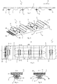
- the toothed belt 1 has a belt-shaped belt body 2, which carries on its one side molded tooth profiles 3, which are arranged distributed uniformly in the longitudinal direction 4 of the toothed belt 1. Die Zahnprofile 1 hrs. are.
- the toothed belt 1 according to the embodiment shown in the figures is characterized in that in a plurality of tooth profiles 3 or even in each of the tooth profiles 3 at least one support roller 5 is integrated, the running surface 6 protrudes beyond the top surface 7 of the associated tooth profile 3 (see example FIG. 4 ), so that the toothed belt 1 can be supported on the support rollers 5 on a guide rail, not shown in the figures. Such as from the Figures 2 .
- a support roller 5 is integrated in every second tooth profile 3 of the toothed belt 1, wherein in the embodiment according to the FIG. 19 even two support rollers 5 are accommodated in a tooth profile 3.
- a support roller 5 may be integrated, as for example in FIG. 20 is shown. Conceivable, however, are embodiments in which only in every third or fourth or every nth, ie integer multiples, tooth profile 3, a support roller 5 is integrated to support the toothed belt 1. However, it has proven to be advantageous to integrate a support roller 5 at least in every second tooth profile 3.
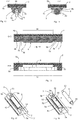
- FIGS. 1 to 10 show in a schematic way a toothed belt 1, in which a first principle of a possible storage of the support rollers 5 is used, whereas the FIGS. 11 to 18 show a toothed belt 1, which has another principle of a possible storage of the support rollers 5. More specifically, the storage of the support rollers 5 takes place in the in the FIGS. 1 to 10 shown embodiment according to the principle of an axis, whereas in the in the FIGS. 11 to 18 shown embodiment, the storage is carried out according to the principle of a shaft.
- each second tooth profile 3 has a respective recess 8 (see for example FIG. 7 or 9 ), which is formed in relation to the width direction 9 of the toothed belt 1 in the center of an associated tooth profile 3 and in which a corresponding support roller 5 is arranged.
- a respective recess 8 thus shares the associated tooth profile 3 in tooth profile sections 3a and 3b, in which the associated support roller 5 is rotatably supported.
- FIG. 3 shows, which in turn is a plan view of a portion of the toothed belt 1 according to the invention. Except for this protruding portion of the tread 6, the in FIG.
- the support rollers 5 are completely within the cross-sectional shape of the respective tooth profiles 3 and the cross-sectional shape of the associated tooth profile sections 3a, 3b added, so that only over the top surface 7 of the respective tooth profiles 3 protruding portion 80 of the respective tread 6 of the associated support roller 5 comes into contact with a guide rail to support the toothed belt 1.
- a respective support roller 5 is rotatably mounted via an axis 11 fixed in the associated tooth profile 3.
- the tooth profile sections 3a and 3b have bores 12a and 12b which receive the longitudinal ends of the axle 11.
- the axle 11, which may be made of steel, is designed at a first longitudinal end 11a as a screw with a threaded portion 11b, so that the axle 11 can be axially secured against slipping out of the bore 12a.
- the diameter of the other bore 12b is slightly smaller than the diameter of the associated second longitudinal end 11c of the axle 11.
- first longitudinal end 11a of the axle 11 is fixed via a kind of threaded connection 14 in the tooth profile section 3a of the associated tooth profile 3, whereas the second longitudinal end 11c the axis 11 is fixed in a press-fit connection 15 in the other tooth profile section 3b of the associated tooth profile 3.
- the axis 11 used in this embodiment is in one piece and corresponds more or less to a special screw with a long cylindrical pin.
- the inclusion of the axis 11 in the tooth profile section 3b in the form of the bore 12b may be performed as well as the bore 12a as a through hole. Manufacturing technology consuming but quite feasible, the bore 12a could alternatively be designed as a blind hole.
- the respective through holes 12a and 12b in the illustrated embodiment have the advantage that both sides of the toothed belt 1 can be drilled and the chips can be better removed from the bores 12a, 12b during machining.
- a narrow trained support roller 5 is provided, wherein the ratio of axial length 16 of the support roller 5 to the belt width 17 in the illustrated embodiment 0.4 (see, for example FIG. 3 ), but also deviating ratio are possible, but should be at least 0.1.
- the axis 11 could be omitted and the support roller 5 instead be designed as a skid.
- the material of the runner to the guide rail less friction than the material of the toothed belt 1, which is preferably polyurethane, produced.
- each second tooth profile 3 has a respective recess 8, which is formed in the middle of the associated tooth profile 3 with respect to the width direction 9 of the toothed belt 1 and the corresponding support roller 5 receives. Also here also shares a respective recess 8, the associated tooth profile 3 in the tooth profile sections 3a, 3b, which receive the associated support roller 5 rotatably.
- a respective recess 8 also has a cup-shaped contour in this embodiment, the sections 8a, 8b extending in the width direction 9 partially following the cross-sectional shape of the tooth profile sections 3a, 3b or corresponding to sections of the original tooth profile 3, such as, in particular FIG. 14 shows a sectional view along the line FF in FIG. 12 is, which in turn is a plan view of the toothed belt 1.
- the recess 8 in a respective tooth profile 3 extends here as well into the belt body 2 and ends just above the longitudinal reinforcing strands 70 (see, for example FIG. 14 ).
- a respective support roller 5 projects with a maximum of one third of its radius 10 beyond the top surface 7 of the associated tooth profile 3.
- the radius 10 is in FIG.
- FIG. 12 shown making a cut along the line EE FIG. 12 shows. Except for this protruding section 80 (see, for example FIG. 14 ) of the tread 6, the support rollers 5 are completely included in the cross-sectional shape of the respective tooth profiles 3 and the cross-sectional shape of the associated tooth profile sections 3a, 3b, so that only the over the top surface 7 of the respective tooth profiles 3 protruding portion 80 of the respective tread 6 of the associated support roller 5 comes into contact with the guide rail.
- the bearing of the support roller 5 is designed according to the principle of a shaft.
- a respective support roller 5 for rotatable mounting serving stub shaft 50 formed, such as out FIG. 18 is apparent.
- the two stub shafts 50 are clipped during assembly in associated snap-51, which are formed in the tooth profile sections 3a, 3b.
- the snap connections 51 comprise elastically deformable retaining arms 52 which allow the stub shafts 50 to be pressed into a respective receiving space 53 formed in the tooth profile sections 3a and 3b, respectively.
- a gap 55 is present, which is smaller than the diameter of the associated stub shaft 50, so that a respective stub shaft 50 after mounting the associated support roller 5 on the timing belt 1 on slip out of the corresponding receiving space 53 is prevented.
- the retaining arms 52 additionally provide slots 54 which extend in the head surface 7 of the tooth profile 3 in the longitudinal direction 4 and limit the retaining arms 52 in the width direction 9.
- intermediate substances or intermediate bodies can be used to minimize the friction between the stub shafts 50 and the receiving spaces 53.
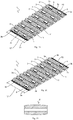
- FIG. 19 shows a further possible embodiment of a toothed belt 1, in which the arranged in the recesses 8 support rollers 5 are arranged in the longitudinal direction 4 of the toothed belt 1 in two rows aligned one behind the other.
- two recesses 8 with respective support roller 5 are provided side by side in the width direction 9 of the toothed belt 1 in each second tooth profile 3, wherein in this example recesses 8 are formed only in each second tooth profile 3.
- two recesses 8 with support rollers 5 can be provided in each tooth profile 3.
- the two recesses 8 divide the tooth profile 3 into tooth profile sections 3a, 3b, 3c, wherein the two support rollers 5 per tooth profile 5 are supported and held by a common axis 11.
- the axis 11 is fixed with its first longitudinal end, which is designed as a screw in the manner of a threaded connection in the tooth profile section 3a, while the second longitudinal end of the axle 11 is fixed via a press fit in the tooth profile section 3b. Between its longitudinal ends, the axis 11 is held by the tooth profile section 3 c, which is arranged between two support rollers 5 of an associated tooth profile 3.
- the ratio of axial length 16 of a respective support roller 5 (the axial length of the support roller 5 in FIG.
- FIG. 20 shows a further modification in which in each tooth profile 3, a recess 8 is formed with support roller 5 mounted therein. Unlike the in FIG. 19 As shown embodiment, the integrated in the tooth profiles 3 support rollers 5 are no longer aligned. Rather, the arranged in the recesses 8 adjacent tooth profiles 3 support rollers 5 in the width direction 9 are offset from one another arranged that the integrated in each second tooth profile 3 support rollers 5 are arranged in the longitudinal direction 4 in alignment with each other.
- FIGS. 19 and 20 shown embodiments, in which the bearing of a respective support roller 5 is designed according to the principle of an axis, also on the principle of storage of a shaft (see FIGS. 11 to 18 ) is transferable. It is also possible to mix the storage principles in a toothed belt, so that support rollers 5 are provided both according to the principle of storage of an axle and according to the principle of storage of a shaft.
- FIGS. 19 and 20 shown ways of providing a support roller 5 in each tooth profile 3 or two support rollers 5 in each second tooth profile 3, purely exemplary way.
- the number of support rollers 3, which is integrated in a tooth profile 3 depends on the belt width and the type of use of the belt from.
- arrangements of two alternately three and three support rollers 5 per tooth profile 3 are conceivable, wherein the support rollers 5 may be arranged offset from one another. Arrangements are therefore possible in which the number of support rollers from tooth profile 3 to tooth profile 3 is different. It will thus be understood that the invention is not limited to the embodiments shown in the figures, but modifications and uses of features of one embodiment shown in the other embodiment are possible.
- the support roller 5 in the embodiments described above has a cylindrical shape.
- a support roller 5 ' which is viewed in an axial section is spherical and designed for the storage principle of the axle.
- the spherical shape of the support roller 5 ' also on the support rollers with stub shaft 50, so on the storage principle in the manner of a wave, transferable.
- the barrel shape is compared to cylindrical support rollers friction and less sensitive to edge wear, wherein Also, a combination is possible, the spherical support rollers 5 'and cylindrical support rollers 5 used in a toothed belt 1.
- a stamped image 90 which serves to develop a finite toothed belt by welding the longitudinal ends 18a and 18b of the toothed belt 1 together.
- the respective longitudinal ends 18a, 18b of the toothed belt 1 have comb-shaped and complementary to each other formed tongues or punching fingers 19a and 19b, which are arranged interlocking to form an endless belt and welded together (see FIG. 10 which is representative of both embodiments).
- the punching fingers 19a, 19b are formed by manufacturing technology through recesses, which are formed in the longitudinal ends 18a, 18b of the toothed belt. How further the FIG.
- the punching image 90 extends in the longitudinal direction 4 of the toothed belt 1 and three tooth profiles 3 with support rollers 5. But also conceivable punching images with a smaller or larger longitudinal extent 91 than those in the FIG. 3 is shown.
- the position of the tension members or reinforcing strands 70 has to be "punch-friendly", which means that no reinforcing strands 70 are longitudinally arranged in the region of a punching line 90 extending in the longitudinal direction 4. This is also the reason why the distances between the reinforcing strands 70 are uneven, such as the Figures 3 and 12 can be seen.
- the cavities of the recesses 8 must be designed so that they are demoldable and do not hinder the welding process.
- At least one support roller 5 is integrated in at least one tooth profile 3, wherein a respective support roller 5 exclusively with a section 80 its tread 6 projects beyond the top surface 7 of the associated tooth profile 3. Only with this section 80 is a respective support roller 5 protruding from the cross section of a respective tooth profile 3, so that the function of the actual tooth profile 3 is still ensured.
- a toothed belt 1 is shown with T-profile. Such a toothed belt carries on the toothed pulley on the belt tooth space. The belt tooth head does not rest in the toothed pulley.
- the existing air is greater than the supernatant of the down from the belt teeth looking out support rollers 5, so that a normal standard toothed disk can be used.
- the AT profile carries over the heads of the teeth.
- the gap bottom of the toothed discs must be adjusted so that in each second tooth gap a cylinder portion is cleared, in which the support roller 5 is immersed, provided that each second tooth profile 3 is equipped with a support roller 5. As a result, only integer numbers of teeth of the toothed disc are allowed.
Landscapes
- Engineering & Computer Science (AREA)
- Mechanical Engineering (AREA)
- General Engineering & Computer Science (AREA)
- Devices For Conveying Motion By Means Of Endless Flexible Members (AREA)
Claims (15)
- Courroie dentée (1) pour transporter des objets, comportant un corps de courroie en forme de bande (2), qui porte des profils de denté (3) conformés sur un de ses côtés, qui sont disposés répartis uniformément dans le sens longitudinal (4) de la courroie dentée (1),
caractérisée en ce
qu'au moins un profil de dent (3) comporte au moins un évidement (8) dans lequel est disposé un rouleau pour le support (5 ; 5') dont la surface de roulement (6) pour supporter la courroie dentée (1) dépasse au-dessus de la surface de tête (7) du profil de dent (3) correspondant. - Courroie dentée (1) selon la revendication 1, caractérisée en ce qu'au moins un évidement (8) sépare en référence au sens de la largeur (9) de la courroie dentée (1), le profil de dent (3) correspondant en sections de profil de dent (3a, 3b, 3c), le rouleau pour le support (5 ; 5') correspondant à l'évidement (8) étant maintenu pouvant tourner dans les sections de profil de dent adjacentes (3a, 3b, 3c) du profil de dent (3) correspondant.
- Courroie dentée (1) selon la revendication 1 ou 2, caractérisée en ce qu'un rouleau pour le support (5 ; 5') respectif dépasse au maximum d'un tiers de son rayon (10) au-dessus de la surface de tête (7) du profil de dent (3) correspondant.
- Courroie dentée (1) selon l'une quelconque des revendications précédentes, caractérisée en ce qu'un évidement respectif (8) dans un profil de dent (3) correspondant présente une forme de section transversale en forme de cuvette et correspondant par tronçon au contour des sections de profil de dent (3a, 3b, 3c) adjacentes dans le sens de la largeur (9) de la courroie dentée et s'étendant jusque dans le corps de courroie (2).
- Courroie dentée (1) selon l'une quelconque des revendications précédentes, caractérisée en ce qu'un rouleau pour le support (5 ; 5') respectif est logé pouvant tourner sur un axe (11) fixé dans le profil de dent (3) correspondant.
- Courroie dentée (1) selon la revendication 5, caractérisée en ce qu'une première extrémité longitudinale (11a) de l'axe (11) est fixée sur un raccord fileté (14) dans une section de profil de dent (3a) d'un profil de dent (3) correspondant et une deuxième extrémité longitudinale (11c) de l'axe (11) est fixée dans un raccord à ajustement serré (15) dans l'autre section de profil de dent (3b) du profil de dent (3) correspondant.
- Courroie dentée (1) selon l'une quelconque des revendications 1 à 4, caractérisée en ce qu'un bout d'arbre (50) servant au logement pouvant tourner est respectivement conformé en extrémité sur un rouleau pour le support (5 ; 5') respectif, les sections de profil de dent (3a, 3b) comportant respectivement un raccord à déclic (51) pour la réception et le logement pouvant tourner d'un bout d'arbre (50) correspondant.
- Courroie dentée (1) selon l'une quelconque des revendications précédentes, caractérisée en ce que le rapport entre la longueur axiale (16) d'un rouleau pour le support (5 ; 5') respectif et la largeur de courroie (17 ; 17') est d'au moins 0,1 et au maximum de 0,65.
- Courroie dentée (1) selon l'une quelconque des revendications précédentes, caractérisée en ce que les extrémités longitudinales (18a, 18b) de la courroie dentée (1) comportent des ergots d'emboutissage (19a, 19b) constitués en forme de peigne et de manière complémentaire les uns par rapport aux autres, qui définissent une image d'emboutissage (90) prédéfinie et qui sont disposés s'engrenant l'un dans l'autre et soudés les uns aux autres pour former une courroie sans fin, l'image d'emboutissage (90) s'étendant dans le sens longitudinal (4) de la courroie dentée (1) sur au moins deux profils de dent (3) avec des rouleaux pour le support (5 ; 5').
- Courroie dentée (1) selon l'une quelconque des revendications précédentes, caractérisée en ce que le corps de courroie (2) comporte des brins de renfort (70) longitudinaux, qui passent exclusivement sur le côté près d'un rouleau pour le support (5 ; 5') respectif ou également en dessous d'un rouleau pour le support (5 ; 5') respectif.
- Courroie dentée (1) selon l'une quelconque des revendications précédentes, caractérisée en ce que les rouleaux pour le support (5 ; 5') disposés dans les évidements (8) sont disposés les uns derrière les autres en alignement dans le sens longitudinal (4) de la courroie dentée (1).
- Courroie dentée (1) selon la revendication 11, caractérisée en ce que dans chaque deuxième profil de dent (3) de la courroie dentée (1) est au moins constitué un évidement (8) recevant un rouleau pour le support (5 ; 5').
- Courroie dentée (1) selon l'une quelconque des revendications 1 à 10, caractérisée en ce que les rouleaux pour le support (5 ; 5') disposés dans les évidements (8) des profils de dent (3) voisins sont disposés dans le sens longitudinal (4) de la courroie dentée dans le sens de la largeur (9) déportés les uns par rapport aux autres.
- Courroie dentée (1) selon l'une quelconque des revendications 1 à 10 ou 14, caractérisée en ce que dans chaque profil de dent (3) de la courroie dentée (1) est constitué au moins un évidement (8) recevant un rouleau pour le support (5 ; 5').
- Courroie dentée (1) selon l'une quelconque des revendications précédentes, caractérisée en ce qu'au moins un rouleau pour le support (5'), vu dans une coupe axiale, est constitué de forme bombée.
Priority Applications (2)
| Application Number | Priority Date | Filing Date | Title |
|---|---|---|---|
| EP15186508.6A EP3147239B1 (fr) | 2015-09-23 | 2015-09-23 | Courroie dentée avec rouleaux intégrés pour le support |
| US15/193,227 US9643788B2 (en) | 2015-09-23 | 2016-06-27 | Toothed belt |
Applications Claiming Priority (1)
| Application Number | Priority Date | Filing Date | Title |
|---|---|---|---|
| EP15186508.6A EP3147239B1 (fr) | 2015-09-23 | 2015-09-23 | Courroie dentée avec rouleaux intégrés pour le support |
Publications (2)
| Publication Number | Publication Date |
|---|---|
| EP3147239A1 EP3147239A1 (fr) | 2017-03-29 |
| EP3147239B1 true EP3147239B1 (fr) | 2018-01-17 |
Family
ID=54199566
Family Applications (1)
| Application Number | Title | Priority Date | Filing Date |
|---|---|---|---|
| EP15186508.6A Active EP3147239B1 (fr) | 2015-09-23 | 2015-09-23 | Courroie dentée avec rouleaux intégrés pour le support |
Country Status (2)
| Country | Link |
|---|---|
| US (1) | US9643788B2 (fr) |
| EP (1) | EP3147239B1 (fr) |
Cited By (1)
| Publication number | Priority date | Publication date | Assignee | Title |
|---|---|---|---|---|
| US10968080B2 (en) * | 2017-10-19 | 2021-04-06 | Otis Elevator Company | Drive belt for people conveyors |
Families Citing this family (9)
| Publication number | Priority date | Publication date | Assignee | Title |
|---|---|---|---|---|
| GB2587297B (en) | 2015-03-31 | 2021-08-04 | Fisher & Paykel Healthcare Ltd | A user interface and system for supplying gases to an airway |
| JP6503244B2 (ja) * | 2015-05-15 | 2019-04-17 | 三ツ星ベルト株式会社 | プロファイル付きベルト及びその製造方法 |
| DE102016002144A1 (de) * | 2016-02-25 | 2017-08-31 | Maschinenfabrik Krone Beteiligungs-GmbH | Fördergurt und landwirtschaftliche Erntemaschinen mit einem Fördergurt |
| DE202016001776U1 (de) * | 2016-03-18 | 2017-06-21 | Gebr. Bode Gmbh & Co. Kg | Zahnriemenantrieb mit Kraftmitnehmern |
| KR20240157114A (ko) | 2016-08-11 | 2024-10-31 | 피셔 앤 페이켈 핼스케어 리미티드 | 압궤 가능 도관, 환자 인터페이스 및 헤드기어 연결부 |
| US10206332B2 (en) * | 2017-04-22 | 2019-02-19 | Deere & Company | Draper belt guide |
| EP3686147B1 (fr) | 2019-01-23 | 2024-03-20 | Otis Elevator Company | Courroie de transport pour convoyeur |
| DE102021118487A1 (de) * | 2021-07-16 | 2023-01-19 | Sit Antriebselemente Gmbh | Verbindungselement zum verbinden von riemenenden und riemenverbindung |
| US12312177B2 (en) * | 2022-01-03 | 2025-05-27 | Fenner, Inc. | D-shaped belt with flanges |
Family Cites Families (11)
| Publication number | Priority date | Publication date | Assignee | Title |
|---|---|---|---|---|
| DE1149665B (de) * | 1960-02-05 | 1963-05-30 | Svenska Aeroplan Ab | Vorrichtung zum Fortbewegen von Lasten auf Walzen |
| GB934810A (en) * | 1960-10-19 | 1963-08-21 | Dominion Malting Ontario Ltd | Stabilizing means for endless conveyors |
| US5042647A (en) * | 1990-05-31 | 1991-08-27 | Griffin & Company | Overlapping, non-leaking conveyor slat for dry bulk materials |
| US5238099A (en) * | 1992-08-04 | 1993-08-24 | Premark Feg Corporation | Conveying system |
| US5911307A (en) * | 1996-10-31 | 1999-06-15 | Burrel Leder Beltech, Inc. | Conveyor belt and method of manufacturing |
| US6364095B1 (en) * | 2000-04-13 | 2002-04-02 | Span Tech Llc | Modular conveyor system with side flexing belt having roller support |
| EP1549574B1 (fr) * | 2002-05-30 | 2010-07-14 | Laitram, L.L.C. | Convoyeur a faible frottement |
| US7527146B2 (en) * | 2006-04-04 | 2009-05-05 | Rexnord Industries, Llc | Conveyor module with a snap fit extension for supporting a roller |
| DE202007014761U1 (de) | 2007-10-12 | 2009-02-19 | Armatec Vierhaus Gmbh | Riemenförderer |
| US8307974B2 (en) * | 2011-01-21 | 2012-11-13 | United Technologies Corporation | Load beam unit replaceable inserts for dry coal extrusion pumps |
| DE202012100232U1 (de) | 2012-01-23 | 2012-02-01 | Breco Antriebstechnik Breher Gmbh & Co. Kg | Zahnriemen |
-
2015
- 2015-09-23 EP EP15186508.6A patent/EP3147239B1/fr active Active
-
2016
- 2016-06-27 US US15/193,227 patent/US9643788B2/en not_active Expired - Fee Related
Non-Patent Citations (1)
| Title |
|---|
| None * |
Cited By (1)
| Publication number | Priority date | Publication date | Assignee | Title |
|---|---|---|---|---|
| US10968080B2 (en) * | 2017-10-19 | 2021-04-06 | Otis Elevator Company | Drive belt for people conveyors |
Also Published As
| Publication number | Publication date |
|---|---|
| US9643788B2 (en) | 2017-05-09 |
| EP3147239A1 (fr) | 2017-03-29 |
| US20170081124A1 (en) | 2017-03-23 |
Similar Documents
| Publication | Publication Date | Title |
|---|---|---|
| EP3147239B1 (fr) | Courroie dentée avec rouleaux intégrés pour le support | |
| EP2289823B1 (fr) | Support pour convoyeur et méthode de fonctionnement du convoyeur | |
| EP2289822B1 (fr) | Dispositif de support pour convoyer des charges lourdes | |
| DE102010034254B4 (de) | Käfig für ein Rollenlager | |
| AT513613B1 (de) | Zahnradanordnung | |
| EP2679522B1 (fr) | Elément de bande convoyeuse pour transporter des articles, procédé de guidage d'un élément de bande convoyeuse et agencement constitué d'un élément de bande convoyeuse et d'un dispositif de guidage et/ou d'entraînement à rouleaux | |
| EP3201494B1 (fr) | Transmission à chaîne munie de plusieurs éléments de glissement | |
| EP2123577B1 (fr) | Elément à rouleaux entraîné | |
| EP1762759B1 (fr) | Mécanisme de commande pour une soupape à vide | |
| DE112012003767B4 (de) | Bewegungsführungsvorrichtung | |
| EP2210831A1 (fr) | Dispositif de transport et élément de transport | |
| WO2011113076A2 (fr) | Convoyeur à courroie et dispositif d'admission et d'évacuation d'un sas | |
| DE102005058152A1 (de) | Käfig für Wälzrollenlager | |
| DE102005041891A1 (de) | Rillenrollenlager | |
| WO2013175294A1 (fr) | Cage de roulement pourvue d'éléments d'écartement | |
| WO2008116707A1 (fr) | Palier à roulement radial | |
| DE102017011293B4 (de) | Laufbahn, Fördereinrichtung und Verfahren zur Montage einer Laufbahn | |
| EP3115641B1 (fr) | Ceinture et element de ceinture | |
| DE19914515C2 (de) | Antriebssystem für Förderrollen in einer Rollenbahn | |
| DE102011104188A1 (de) | Rollenförderer mit kammartigem Förderstreckenlagerelement | |
| EP2687465B1 (fr) | Transport roller with profile | |
| DE102014218301A1 (de) | Planetenwälzlager | |
| DE4316647C2 (de) | Hubgerüst mit zwei relativ zueinander längsbeweglichen Bauteilen und dazwischen angeordneten Lagerstellen | |
| DE102013212963A1 (de) | Ketten- oder Riemenumlenkrolle | |
| EP3686449A1 (fr) | Rail télescopique pourvu d'au moins trois éléments de rail |
Legal Events
| Date | Code | Title | Description |
|---|---|---|---|
| PUAI | Public reference made under article 153(3) epc to a published international application that has entered the european phase |
Free format text: ORIGINAL CODE: 0009012 |
|
| STAA | Information on the status of an ep patent application or granted ep patent |
Free format text: STATUS: THE APPLICATION HAS BEEN PUBLISHED |
|
| AK | Designated contracting states |
Kind code of ref document: A1 Designated state(s): AL AT BE BG CH CY CZ DE DK EE ES FI FR GB GR HR HU IE IS IT LI LT LU LV MC MK MT NL NO PL PT RO RS SE SI SK SM TR |
|
| AX | Request for extension of the european patent |
Extension state: BA ME |
|
| 17P | Request for examination filed |
Effective date: 20170427 |
|
| RBV | Designated contracting states (corrected) |
Designated state(s): AL AT BE BG CH CY CZ DE DK EE ES FI FR GB GR HR HU IE IS IT LI LT LU LV MC MK MT NL NO PL PT RO RS SE SI SK SM TR |
|
| STAA | Information on the status of an ep patent application or granted ep patent |
Free format text: STATUS: REQUEST FOR EXAMINATION WAS MADE |
|
| GRAP | Despatch of communication of intention to grant a patent |
Free format text: ORIGINAL CODE: EPIDOSNIGR1 |
|
| STAA | Information on the status of an ep patent application or granted ep patent |
Free format text: STATUS: GRANT OF PATENT IS INTENDED |
|
| INTG | Intention to grant announced |
Effective date: 20170921 |
|
| GRAS | Grant fee paid |
Free format text: ORIGINAL CODE: EPIDOSNIGR3 |
|
| GRAA | (expected) grant |
Free format text: ORIGINAL CODE: 0009210 |
|
| STAA | Information on the status of an ep patent application or granted ep patent |
Free format text: STATUS: THE PATENT HAS BEEN GRANTED |
|
| AK | Designated contracting states |
Kind code of ref document: B1 Designated state(s): AL AT BE BG CH CY CZ DE DK EE ES FI FR GB GR HR HU IE IS IT LI LT LU LV MC MK MT NL NO PL PT RO RS SE SI SK SM TR |
|
| REG | Reference to a national code |
Ref country code: GB Ref legal event code: FG4D Free format text: NOT ENGLISH |
|
| REG | Reference to a national code |
Ref country code: CH Ref legal event code: EP |
|
| REG | Reference to a national code |
Ref country code: IE Ref legal event code: FG4D Free format text: LANGUAGE OF EP DOCUMENT: GERMAN |
|
| REG | Reference to a national code |
Ref country code: AT Ref legal event code: REF Ref document number: 964237 Country of ref document: AT Kind code of ref document: T Effective date: 20180215 |
|
| REG | Reference to a national code |
Ref country code: DE Ref legal event code: R096 Ref document number: 502015002868 Country of ref document: DE |
|
| REG | Reference to a national code |
Ref country code: NL Ref legal event code: FP |
|
| REG | Reference to a national code |
Ref country code: SE Ref legal event code: TRGR |
|
| REG | Reference to a national code |
Ref country code: LT Ref legal event code: MG4D |
|
| PG25 | Lapsed in a contracting state [announced via postgrant information from national office to epo] |
Ref country code: ES Free format text: LAPSE BECAUSE OF FAILURE TO SUBMIT A TRANSLATION OF THE DESCRIPTION OR TO PAY THE FEE WITHIN THE PRESCRIBED TIME-LIMIT Effective date: 20180117 Ref country code: NO Free format text: LAPSE BECAUSE OF FAILURE TO SUBMIT A TRANSLATION OF THE DESCRIPTION OR TO PAY THE FEE WITHIN THE PRESCRIBED TIME-LIMIT Effective date: 20180417 Ref country code: HR Free format text: LAPSE BECAUSE OF FAILURE TO SUBMIT A TRANSLATION OF THE DESCRIPTION OR TO PAY THE FEE WITHIN THE PRESCRIBED TIME-LIMIT Effective date: 20180117 Ref country code: CY Free format text: LAPSE BECAUSE OF FAILURE TO SUBMIT A TRANSLATION OF THE DESCRIPTION OR TO PAY THE FEE WITHIN THE PRESCRIBED TIME-LIMIT Effective date: 20180117 Ref country code: LT Free format text: LAPSE BECAUSE OF FAILURE TO SUBMIT A TRANSLATION OF THE DESCRIPTION OR TO PAY THE FEE WITHIN THE PRESCRIBED TIME-LIMIT Effective date: 20180117 Ref country code: FI Free format text: LAPSE BECAUSE OF FAILURE TO SUBMIT A TRANSLATION OF THE DESCRIPTION OR TO PAY THE FEE WITHIN THE PRESCRIBED TIME-LIMIT Effective date: 20180117 |
|
| PG25 | Lapsed in a contracting state [announced via postgrant information from national office to epo] |
Ref country code: IS Free format text: LAPSE BECAUSE OF FAILURE TO SUBMIT A TRANSLATION OF THE DESCRIPTION OR TO PAY THE FEE WITHIN THE PRESCRIBED TIME-LIMIT Effective date: 20180517 Ref country code: BG Free format text: LAPSE BECAUSE OF FAILURE TO SUBMIT A TRANSLATION OF THE DESCRIPTION OR TO PAY THE FEE WITHIN THE PRESCRIBED TIME-LIMIT Effective date: 20180417 Ref country code: PL Free format text: LAPSE BECAUSE OF FAILURE TO SUBMIT A TRANSLATION OF THE DESCRIPTION OR TO PAY THE FEE WITHIN THE PRESCRIBED TIME-LIMIT Effective date: 20180117 Ref country code: GR Free format text: LAPSE BECAUSE OF FAILURE TO SUBMIT A TRANSLATION OF THE DESCRIPTION OR TO PAY THE FEE WITHIN THE PRESCRIBED TIME-LIMIT Effective date: 20180418 Ref country code: LV Free format text: LAPSE BECAUSE OF FAILURE TO SUBMIT A TRANSLATION OF THE DESCRIPTION OR TO PAY THE FEE WITHIN THE PRESCRIBED TIME-LIMIT Effective date: 20180117 Ref country code: RS Free format text: LAPSE BECAUSE OF FAILURE TO SUBMIT A TRANSLATION OF THE DESCRIPTION OR TO PAY THE FEE WITHIN THE PRESCRIBED TIME-LIMIT Effective date: 20180117 |
|
| REG | Reference to a national code |
Ref country code: FR Ref legal event code: PLFP Year of fee payment: 4 |
|
| PG25 | Lapsed in a contracting state [announced via postgrant information from national office to epo] |
Ref country code: MT Free format text: LAPSE BECAUSE OF FAILURE TO SUBMIT A TRANSLATION OF THE DESCRIPTION OR TO PAY THE FEE WITHIN THE PRESCRIBED TIME-LIMIT Effective date: 20180117 |
|
| REG | Reference to a national code |
Ref country code: DE Ref legal event code: R097 Ref document number: 502015002868 Country of ref document: DE |
|
| PG25 | Lapsed in a contracting state [announced via postgrant information from national office to epo] |
Ref country code: EE Free format text: LAPSE BECAUSE OF FAILURE TO SUBMIT A TRANSLATION OF THE DESCRIPTION OR TO PAY THE FEE WITHIN THE PRESCRIBED TIME-LIMIT Effective date: 20180117 Ref country code: AL Free format text: LAPSE BECAUSE OF FAILURE TO SUBMIT A TRANSLATION OF THE DESCRIPTION OR TO PAY THE FEE WITHIN THE PRESCRIBED TIME-LIMIT Effective date: 20180117 Ref country code: RO Free format text: LAPSE BECAUSE OF FAILURE TO SUBMIT A TRANSLATION OF THE DESCRIPTION OR TO PAY THE FEE WITHIN THE PRESCRIBED TIME-LIMIT Effective date: 20180117 |
|
| PLBE | No opposition filed within time limit |
Free format text: ORIGINAL CODE: 0009261 |
|
| STAA | Information on the status of an ep patent application or granted ep patent |
Free format text: STATUS: NO OPPOSITION FILED WITHIN TIME LIMIT |
|
| PG25 | Lapsed in a contracting state [announced via postgrant information from national office to epo] |
Ref country code: CZ Free format text: LAPSE BECAUSE OF FAILURE TO SUBMIT A TRANSLATION OF THE DESCRIPTION OR TO PAY THE FEE WITHIN THE PRESCRIBED TIME-LIMIT Effective date: 20180117 Ref country code: SK Free format text: LAPSE BECAUSE OF FAILURE TO SUBMIT A TRANSLATION OF THE DESCRIPTION OR TO PAY THE FEE WITHIN THE PRESCRIBED TIME-LIMIT Effective date: 20180117 Ref country code: SM Free format text: LAPSE BECAUSE OF FAILURE TO SUBMIT A TRANSLATION OF THE DESCRIPTION OR TO PAY THE FEE WITHIN THE PRESCRIBED TIME-LIMIT Effective date: 20180117 Ref country code: DK Free format text: LAPSE BECAUSE OF FAILURE TO SUBMIT A TRANSLATION OF THE DESCRIPTION OR TO PAY THE FEE WITHIN THE PRESCRIBED TIME-LIMIT Effective date: 20180117 |
|
| 26N | No opposition filed |
Effective date: 20181018 |
|
| PG25 | Lapsed in a contracting state [announced via postgrant information from national office to epo] |
Ref country code: SI Free format text: LAPSE BECAUSE OF FAILURE TO SUBMIT A TRANSLATION OF THE DESCRIPTION OR TO PAY THE FEE WITHIN THE PRESCRIBED TIME-LIMIT Effective date: 20180117 |
|
| PG25 | Lapsed in a contracting state [announced via postgrant information from national office to epo] |
Ref country code: MC Free format text: LAPSE BECAUSE OF FAILURE TO SUBMIT A TRANSLATION OF THE DESCRIPTION OR TO PAY THE FEE WITHIN THE PRESCRIBED TIME-LIMIT Effective date: 20180117 |
|
| REG | Reference to a national code |
Ref country code: IE Ref legal event code: MM4A |
|
| PG25 | Lapsed in a contracting state [announced via postgrant information from national office to epo] |
Ref country code: LU Free format text: LAPSE BECAUSE OF NON-PAYMENT OF DUE FEES Effective date: 20180923 |
|
| PG25 | Lapsed in a contracting state [announced via postgrant information from national office to epo] |
Ref country code: IE Free format text: LAPSE BECAUSE OF NON-PAYMENT OF DUE FEES Effective date: 20180923 |
|
| PG25 | Lapsed in a contracting state [announced via postgrant information from national office to epo] |
Ref country code: TR Free format text: LAPSE BECAUSE OF FAILURE TO SUBMIT A TRANSLATION OF THE DESCRIPTION OR TO PAY THE FEE WITHIN THE PRESCRIBED TIME-LIMIT Effective date: 20180117 |
|
| PG25 | Lapsed in a contracting state [announced via postgrant information from national office to epo] |
Ref country code: PT Free format text: LAPSE BECAUSE OF FAILURE TO SUBMIT A TRANSLATION OF THE DESCRIPTION OR TO PAY THE FEE WITHIN THE PRESCRIBED TIME-LIMIT Effective date: 20180117 |
|
| PG25 | Lapsed in a contracting state [announced via postgrant information from national office to epo] |
Ref country code: HU Free format text: LAPSE BECAUSE OF FAILURE TO SUBMIT A TRANSLATION OF THE DESCRIPTION OR TO PAY THE FEE WITHIN THE PRESCRIBED TIME-LIMIT; INVALID AB INITIO Effective date: 20150923 Ref country code: MK Free format text: LAPSE BECAUSE OF NON-PAYMENT OF DUE FEES Effective date: 20180117 |
|
| P01 | Opt-out of the competence of the unified patent court (upc) registered |
Effective date: 20230414 |
|
| PGFP | Annual fee paid to national office [announced via postgrant information from national office to epo] |
Ref country code: NL Payment date: 20230920 Year of fee payment: 9 Ref country code: GB Payment date: 20230920 Year of fee payment: 9 Ref country code: AT Payment date: 20230921 Year of fee payment: 9 |
|
| PGFP | Annual fee paid to national office [announced via postgrant information from national office to epo] |
Ref country code: SE Payment date: 20230920 Year of fee payment: 9 Ref country code: FR Payment date: 20230928 Year of fee payment: 9 Ref country code: DE Payment date: 20230930 Year of fee payment: 9 Ref country code: BE Payment date: 20230920 Year of fee payment: 9 |
|
| PGFP | Annual fee paid to national office [announced via postgrant information from national office to epo] |
Ref country code: IT Payment date: 20230927 Year of fee payment: 9 Ref country code: CH Payment date: 20231001 Year of fee payment: 9 |
|
| REG | Reference to a national code |
Ref country code: DE Ref legal event code: R119 Ref document number: 502015002868 Country of ref document: DE |
|
| REG | Reference to a national code |
Ref country code: SE Ref legal event code: EUG |
|
| REG | Reference to a national code |
Ref country code: CH Ref legal event code: PL |
|
| REG | Reference to a national code |
Ref country code: NL Ref legal event code: MM Effective date: 20241001 |
|
| REG | Reference to a national code |
Ref country code: AT Ref legal event code: MM01 Ref document number: 964237 Country of ref document: AT Kind code of ref document: T Effective date: 20240923 |
|
| GBPC | Gb: european patent ceased through non-payment of renewal fee |
Effective date: 20240923 |
|
| PG25 | Lapsed in a contracting state [announced via postgrant information from national office to epo] |
Ref country code: NL Free format text: LAPSE BECAUSE OF NON-PAYMENT OF DUE FEES Effective date: 20241001 |
|
| PG25 | Lapsed in a contracting state [announced via postgrant information from national office to epo] |
Ref country code: DE Free format text: LAPSE BECAUSE OF NON-PAYMENT OF DUE FEES Effective date: 20250401 |
|
| PG25 | Lapsed in a contracting state [announced via postgrant information from national office to epo] |
Ref country code: GB Free format text: LAPSE BECAUSE OF NON-PAYMENT OF DUE FEES Effective date: 20240923 |
|
| REG | Reference to a national code |
Ref country code: BE Ref legal event code: MM Effective date: 20240930 |
|
| PG25 | Lapsed in a contracting state [announced via postgrant information from national office to epo] |
Ref country code: BE Free format text: LAPSE BECAUSE OF NON-PAYMENT OF DUE FEES Effective date: 20240930 Ref country code: IT Free format text: LAPSE BECAUSE OF NON-PAYMENT OF DUE FEES Effective date: 20240923 |
|
| PG25 | Lapsed in a contracting state [announced via postgrant information from national office to epo] |
Ref country code: FR Free format text: LAPSE BECAUSE OF NON-PAYMENT OF DUE FEES Effective date: 20240930 |
|
| PG25 | Lapsed in a contracting state [announced via postgrant information from national office to epo] |
Ref country code: CH Free format text: LAPSE BECAUSE OF NON-PAYMENT OF DUE FEES Effective date: 20240930 |
|
| PG25 | Lapsed in a contracting state [announced via postgrant information from national office to epo] |
Ref country code: AT Free format text: LAPSE BECAUSE OF NON-PAYMENT OF DUE FEES Effective date: 20240923 |
|
| PG25 | Lapsed in a contracting state [announced via postgrant information from national office to epo] |
Ref country code: SE Free format text: LAPSE BECAUSE OF NON-PAYMENT OF DUE FEES Effective date: 20240924 |