EP3147251A1 - Verfahren zur herstellung eines gestrichenen tragenden bauteils einer lasthandhabungsvorrichtung zur verwendung auf einem strassenfahrzeug - Google Patents
Verfahren zur herstellung eines gestrichenen tragenden bauteils einer lasthandhabungsvorrichtung zur verwendung auf einem strassenfahrzeug Download PDFInfo
- Publication number
- EP3147251A1 EP3147251A1 EP15186778.5A EP15186778A EP3147251A1 EP 3147251 A1 EP3147251 A1 EP 3147251A1 EP 15186778 A EP15186778 A EP 15186778A EP 3147251 A1 EP3147251 A1 EP 3147251A1
- Authority
- EP
- European Patent Office
- Prior art keywords
- structural member
- plates
- reinforcement plate
- reinforcement
- painted
- Prior art date
- Legal status (The legal status is an assumption and is not a legal conclusion. Google has not performed a legal analysis and makes no representation as to the accuracy of the status listed.)
- Withdrawn
Links
Images
Classifications
-
- B—PERFORMING OPERATIONS; TRANSPORTING
- B66—HOISTING; LIFTING; HAULING
- B66C—CRANES; LOAD-ENGAGING ELEMENTS OR DEVICES FOR CRANES, CAPSTANS, WINCHES, OR TACKLES
- B66C23/00—Cranes comprising essentially a beam, boom, or triangular structure acting as a cantilever and mounted for translatory of swinging movements in vertical or horizontal planes or a combination of such movements, e.g. jib-cranes, derricks, tower cranes
- B66C23/62—Constructional features or details
- B66C23/64—Jibs
Definitions
- the present invention relates to a method for producing a painted load-bearing structural member of a load handling appliance for use on a lorry or other road vehicle.
- a load-bearing structural member in the form of a crane boom of a loader crane or forestry crane to be mounted to a lorry is normally made of steel.
- Reinforcement plates of steel may be secured to the crane boom at specific areas where the crane boom is subjected to particularly high strains and stresses, such as for instance around through holes in the crane boom where shafts included in pivotal connections between the crane boom and other parts of the crane are received.
- the reinforcement plates are normally secured to the crane boom by welding before the final finishing and painting of the crane boom, wherein each reinforcement plate is secured to the crane boom by a welding seam extending around the reinforcement plate along the outer rim thereof.
- the object of the present invention is to provide a new and favourable method for producing a painted load-bearing structural member of a load handling appliance for use on a lorry or other road vehicle.
- the method of the present invention comprises the following steps:
- a painted reinforcement plate of steel may be secured to a painted load-bearing structural member of steel with sufficient bonding strength by means of acrylate adhesive.
- adhesive for securing the reinforcement plates to the structural member implies that each reinforcement plate may be bonded to the structural member over the entire interface surface between the reinforcement plate and the structural member, in contrast to the previously used welding technique which only allows a reinforcement plate to be bonded to the structural member along the outer rim of the reinforcement plate.
- the increased bonding area makes it possible to reduce the size of the reinforcement plates.
- Another advantage associated with the use of adhesive for securing the reinforcement plates to the structural member is that the adhesive does not impair the fatigue strength of the steel material at the joints between the reinforcement plates and the structural member, in contrast to the previously used welding technique which results in a reduced fatigue strength of the steel material at the joints between the reinforcement plates and the structural member.
- the fact that the fatigue strength of the steel material remains unaffected when a reinforcement plate is secured to the structural member by means of adhesive implies that higher stresses can be tolerated, which in its turn implies that thinner reinforcement plates can be used as compared to the case when the reinforcement plates are secured to the structural member by welding.
- the material consumption and material cost for a produced structural member and the weight thereof may be reduced as compared to a corresponding structural member where the reinforcement plates are secured to the structural member by welding.
- the first corrosion protection layer applied to the structural member and to the reinforcement plate or plates is a nano-ceramic coating, wherein the nano-ceramic coating is applied to the structural member and to the reinforcement plate or plates by dipping the structural member and each reinforcement plate into an aqueous or solvent-based solution comprising organo-ceramic nanoparticles, preferably organo-silane nanoparticles.
- the nano-ceramic coating technique is a well-known type of coating technique for forming a thin and dense coating on a metal surface. The strong chemical bond between the nanoparticles of the nano-ceramic coating and the metal surface of the structural member and the reinforcement plate or plates will, along with the ultra dense structure of the coating, significantly improve the corrosion resistance of the metal surface.
- the material of the nano-ceramic coating will also form a strong chemical bond with the next layer of coating material applied to the structural member and to the reinforcement plate or plates and will thereby contribute to an excellent adhesion of the outer layer of paint to the structural member and to the reinforcement plate or plates.
- a second corrosion protection layer is applied by means of cathodic electrodeposition onto the first corrosion protection layer of the structural member and the reinforcement plate or plates in step b.
- the second corrosion protection layer will further enhance the corrosion resistance of the metal surface of the structural member and the reinforcement plate or plates.
- the outer layer of paint applied to the structural member and to the reinforcement plate or plates is a powder coating which is applied electrostatically to the structural member and to the reinforcement plate or plates.
- the powder coating will create a hard and durable finish which is capable of withstanding harsh working environments and which will constitute an excellent contact surface for the adhesive to be applied over the interface between each reinforcement plate and the structural member.
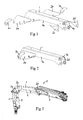
- Fig 1 shows a load-bearing structural member 1 in the form of a crane boom of a hydraulic loader crane. Reinforcement plates 2a-2d to be secured to the structural member 1 and reinforcement plates 3a, 2b to be secured to one of the first-mentioned reinforcement plates 2a-2d are also shown in Fig 1 .
- a first reinforcement plate 2a is to be secured to an outer surface of a first lateral wall 4a of the structural member 1 at a rear end of the wall
- a second reinforcement plate 2b is to be secured to an outer surface of an opposite second lateral wall 4b of the structural member 1 at a rear end of the wall
- a third reinforcement plate 2c is to be secured to an inner surface of the first lateral wall 4a at a front end of the wall
- a fourth reinforcement plate 2d is to be secured to an inner surface of the second lateral wall 4b at a front end of the wall
- a fifth reinforcement plate 3a is to be secured to an outer surface of the first reinforcement plate 2a
- a sixth reinforcement plate 3b is to be secured to an outer surface of the second reinforcement plate 2b.
- the structural member 1 and the reinforcement plates 2a-2d, 3a, 3b are made of steel.
- Fig 2 shows the structural member 1 with the first, second, third and fourth reinforcement plates 2a-2d secured to the structural member by means of acrylate adhesive and with the fifth and sixth reinforcement plates 3a, 3b secured to the first reinforcement plate 2a and the second reinforcement plate 2b, respectively, by means of acrylate adhesive.
- the acrylate adhesive is preferably methyl methacrylate adhesive.
- each reinforcement plate 2a-2d, 3a, 3b are coated with at least one first corrosion protection layer and an outer layer of paint before the reinforcement plates are secured to the structural member or to another reinforcement plate.
- the surfaces of the structural member 1 and the reinforcement plates 2a-2d, 3a, 3b are thoroughly cleaned in a suitable manner.
- the structural member 1 and the reinforcement plates 2a-2d, 3a, 3b may for instance be subjected to cleaning in a first step, followed by blasting in a second step and then final cleaning in a third step.
- the blasting will remove welding impurities and any remaining corrosion or layers of scale from the surfaces of the structural member 1 and the reinforcement plates 2a-2d, 3a, 3b.
- the blasting will also enhance the adhesion properties of the surfaces of the structural member 1 and the reinforcement plates 2a-2d, 3a, 3b and thereby improve the adherence between these surfaces and the coatings to be applied to them.
- the first corrosion protection layer applied to the structural member 1 and to the reinforcement plates 2a-2d, 3a, 3b is a nano-ceramic coating, which is applied to the structural member 1 and to the reinforcement plates 2a-2d, 3a, 3b by dipping the structural member and the reinforcement plates into an aqueous or solvent-based solution comprising organo-ceramic nanoparticles, preferably organo-silane nanoparticles.
- the nano-ceramic coating technique is a well-known coating technique which may be carried out by means of suitable chemical compositions marketed by different suppliers.
- the nano-ceramic coating technique applied to the structural member 1 and to the reinforcement plates 2a-2d, 3a, 3b will result in the formation of a thin and dense coating on the surfaces of the structural member 1 and the reinforcement plates 2a-2d, 3a, 3b and with a strong chemical bond between the nanoparticles of the nano-ceramic coating and the surfaces of the structural member 1 and the reinforcement plates 2a-2d, 3a, 3b.
- CED cathodic electrodeposition
- the outer layer of paint applied to the surfaces of the structural member 1 and to the surfaces of the reinforcement plates 2a-2d, 3a, 3b is a with advantage a powder coating which is applied electrostatically to the structural member 1 and to the reinforcement plates 2a-2d, 3a, 3b in a conventional manner.
- the paint powder is baked onto the component under heat, for instance by means of convection heating at a temperature of 150-190° C, so as to allow the paint powder to form a uniform coating on the component, whereupon the coating is allowed to cure at room temperature until it has attained its maximum hardness.
- the reinforcement plates and the structural member are subjected to degreasing.
- the first, second, third and fourth reinforcement plates 2a-2d are secured to the structural member 1 by means of acrylate adhesive, preferably methyl methacrylate adhesive, applied over the entire, or at least essentially the entire, interface between each reinforcement plate 2a-2d and the structural member 1
- the fifth and sixth reinforcement plates 3a, 3b are secured to the first reinforcement plate 2a and the second reinforcement plate 2b, respectively, by means of acrylate adhesive, preferably methyl methacrylate adhesive, applied over the entire, or at least essentially the entire, interface between the first and fifth reinforcement plates 2a, 3a and between the second and sixth reinforcement plates 2b, 3b.
- the application of the acrylate adhesive to the structural member 1 and to the reinforcement plates 2a-2d, 3a, 3b and the subsequent curing thereof may be carried out at room temperature.
- the structural member 1 shown in Figs 1 and 2 is a so-called inner boom to be included in a load handling appliance in the form of a hydraulic loader crane 5 of the type illustrated in Fig 3 .
- This loader crane 5 is intended to be mounted to a road vehicle, for instance in the form of a lorry.
- the loader crane 5 further comprises a rotatable column 6 and an outer boom 7, wherein the inner boom 1 at its inner end is articulately connected to the column 6 and at its outer end is articulately connected to the outer boom 7.
- the inner boom 1 is pivotable in relation to the column 6 by means of a first hydraulic cylinder 8 and the outer boom 7 is pivotable in relation to the inner boom 1 by means of a second hydraulic cylinder 9.
- the column 6 and/or the outer boom 7 and/or any other load-bearing structural member of the loader crane 5 may also be produced by the method according to the present invention.
- a painted load-bearing structural member 1 produced by the method according to the present invention may also be a part of another type of load handling appliance, such as for instance a part of a forestry crane or other type of vehicle crane, a part of a hooklift, a part of a truck-mounted forklift or a part of a tail lift.
Landscapes
- Engineering & Computer Science (AREA)
- Mechanical Engineering (AREA)
- Laminated Bodies (AREA)
Priority Applications (1)
| Application Number | Priority Date | Filing Date | Title |
|---|---|---|---|
| EP15186778.5A EP3147251A1 (de) | 2015-09-25 | 2015-09-25 | Verfahren zur herstellung eines gestrichenen tragenden bauteils einer lasthandhabungsvorrichtung zur verwendung auf einem strassenfahrzeug |
Applications Claiming Priority (1)
| Application Number | Priority Date | Filing Date | Title |
|---|---|---|---|
| EP15186778.5A EP3147251A1 (de) | 2015-09-25 | 2015-09-25 | Verfahren zur herstellung eines gestrichenen tragenden bauteils einer lasthandhabungsvorrichtung zur verwendung auf einem strassenfahrzeug |
Publications (1)
| Publication Number | Publication Date |
|---|---|
| EP3147251A1 true EP3147251A1 (de) | 2017-03-29 |
Family
ID=54199076
Family Applications (1)
| Application Number | Title | Priority Date | Filing Date |
|---|---|---|---|
| EP15186778.5A Withdrawn EP3147251A1 (de) | 2015-09-25 | 2015-09-25 | Verfahren zur herstellung eines gestrichenen tragenden bauteils einer lasthandhabungsvorrichtung zur verwendung auf einem strassenfahrzeug |
Country Status (1)
| Country | Link |
|---|---|
| EP (1) | EP3147251A1 (de) |
Citations (4)
| Publication number | Priority date | Publication date | Assignee | Title |
|---|---|---|---|---|
| GB1193544A (en) * | 1968-02-28 | 1970-06-03 | Jones Cranes Ltd | Improvements in or relating to Cranes. |
| EP0723819A2 (de) * | 1994-12-27 | 1996-07-31 | National Crane Corporation | Schutzüberzug auf Stahlteilen |
| DE202010003617U1 (de) * | 2009-06-19 | 2010-10-28 | Liebherr-Hydraulikbagger Gmbh | Baggerstiel |
| US20130048425A1 (en) * | 2011-08-30 | 2013-02-28 | Altec Industries, Inc. | Dielectric coating and application process |
-
2015
- 2015-09-25 EP EP15186778.5A patent/EP3147251A1/de not_active Withdrawn
Patent Citations (4)
| Publication number | Priority date | Publication date | Assignee | Title |
|---|---|---|---|---|
| GB1193544A (en) * | 1968-02-28 | 1970-06-03 | Jones Cranes Ltd | Improvements in or relating to Cranes. |
| EP0723819A2 (de) * | 1994-12-27 | 1996-07-31 | National Crane Corporation | Schutzüberzug auf Stahlteilen |
| DE202010003617U1 (de) * | 2009-06-19 | 2010-10-28 | Liebherr-Hydraulikbagger Gmbh | Baggerstiel |
| US20130048425A1 (en) * | 2011-08-30 | 2013-02-28 | Altec Industries, Inc. | Dielectric coating and application process |
Similar Documents
| Publication | Publication Date | Title |
|---|---|---|
| US9139227B2 (en) | Axle support for a vehicle, in particular for a motor vehicle, and method for the production of such an axle support | |
| CN109476201A (zh) | 车辆用弹簧及其制造方法 | |
| JP2010513706A5 (de) | ||
| CN103572351B (zh) | 碳纤维增强塑料构件以及用于形成防腐蚀层的方法和装置 | |
| JP2019027593A5 (de) | ||
| CN106164343A (zh) | 用于钝化金属表面的方法 | |
| CN107406957B (zh) | 包括局部加强的经涂覆的钢板的用于车辆的面板 | |
| CN204784105U (zh) | 用于总装钣金件防腐的凸焊垫圈 | |
| WO2013104397A2 (de) | Metallisches trägerbauteil mit verbundhaftungsoberfläche, hybridbauteil und herstellungsverfahren | |
| JP3930841B2 (ja) | 高付着防食被膜付き鉄筋材及びその製造方法 | |
| JP5664953B2 (ja) | 鋳鉄管の複層塗膜の形成方法 | |
| JP2010522104A (ja) | 多層被覆された金属基体及びその製造方法 | |
| US10618244B2 (en) | Pipe product and method for producing same | |
| JP6080807B2 (ja) | 塗装金属素形材、複合体およびそれらの製造方法 | |
| CN105127078A (zh) | 一种对铝材表面进行静电氟碳喷涂的工艺方法 | |
| WO2020130476A3 (ko) | 내식성 및 피로특성이 우수한 도금강판 용접부재의 제조방법 | |
| CN103540990B (zh) | 一种青花瓷涂装方法 | |
| CN2923742Y (zh) | 修补强化焊接部位的超陶防腐涂层 | |
| JP4319995B2 (ja) | 高付着防食被膜付き鉄筋材及びその製造方法 | |
| CN210970139U (zh) | 一种耐腐蚀型超疏水板材 | |
| JP6623543B2 (ja) | 有機樹脂被覆鋼材 | |
| JP2014083530A (ja) | 樹脂塗装鉄筋の製造方法及び樹脂塗装鉄筋 | |
| JP3219002B2 (ja) | セメント含有材料との密着性に優れた表面処理鋼板 | |
| CN109530187A (zh) | 润滑涂层的喷涂方法 | |
| CN108622549A (zh) | 分片组装式集装箱及其制造工艺方法 |
Legal Events
| Date | Code | Title | Description |
|---|---|---|---|
| PUAI | Public reference made under article 153(3) epc to a published international application that has entered the european phase |
Free format text: ORIGINAL CODE: 0009012 |
|
| AK | Designated contracting states |
Kind code of ref document: A1 Designated state(s): AL AT BE BG CH CY CZ DE DK EE ES FI FR GB GR HR HU IE IS IT LI LT LU LV MC MK MT NL NO PL PT RO RS SE SI SK SM TR |
|
| AX | Request for extension of the european patent |
Extension state: BA ME |
|
| STAA | Information on the status of an ep patent application or granted ep patent |
Free format text: STATUS: THE APPLICATION IS DEEMED TO BE WITHDRAWN |
|
| 18D | Application deemed to be withdrawn |
Effective date: 20170930 |