EP3147410A1 - Konstruktionsverfahren und struktur für druckdispergierenden expansionskopfankerstab - Google Patents
Konstruktionsverfahren und struktur für druckdispergierenden expansionskopfankerstab Download PDFInfo
- Publication number
- EP3147410A1 EP3147410A1 EP15795723.4A EP15795723A EP3147410A1 EP 3147410 A1 EP3147410 A1 EP 3147410A1 EP 15795723 A EP15795723 A EP 15795723A EP 3147410 A1 EP3147410 A1 EP 3147410A1
- Authority
- EP
- European Patent Office
- Prior art keywords
- cement
- cut
- paste
- anchor
- pressure
- Prior art date
- Legal status (The legal status is an assumption and is not a legal conclusion. Google has not performed a legal analysis and makes no representation as to the accuracy of the status listed.)
- Granted
Links
Images


Classifications
-
- E—FIXED CONSTRUCTIONS
- E02—HYDRAULIC ENGINEERING; FOUNDATIONS; SOIL SHIFTING
- E02D—FOUNDATIONS; EXCAVATIONS; EMBANKMENTS; UNDERGROUND OR UNDERWATER STRUCTURES
- E02D5/00—Bulkheads, piles, or other structural elements specially adapted to foundation engineering
- E02D5/74—Means for anchoring structural elements or bulkheads
- E02D5/80—Ground anchors
- E02D5/808—Ground anchors anchored by using exclusively a bonding material
-
- E—FIXED CONSTRUCTIONS
- E02—HYDRAULIC ENGINEERING; FOUNDATIONS; SOIL SHIFTING
- E02D—FOUNDATIONS; EXCAVATIONS; EMBANKMENTS; UNDERGROUND OR UNDERWATER STRUCTURES
- E02D5/00—Bulkheads, piles, or other structural elements specially adapted to foundation engineering
- E02D5/74—Means for anchoring structural elements or bulkheads
Definitions
- the present invention relates to a construction method of a jet spouting anchor and a structure of the spouting anchor, belonging to the technical field of soil drilling of fixed buildings.
- Jet spouting anchoring is an effective soil body supporting, protecting and reinforcing technology, has been widely applied at home and abroad, and has advantages of low cost, quick effect, etc.
- a traditional jet spouting anchor is provided with a 5-10 long anchoring segment.
- the cement in the anchoring segment accounts for 12%-18%, and the strength of cement soil is relatively low in the 7-30 days. Due to the low strength, the anchor cannot be made into a pressure-type anchor, and can only be made as a tension-type anchor.
- the anti-pulling force of the anchor is provided by the lateral friction force between the anchoring segment and soil body.
- the anti-pulling force of the anchor is usually low, obviously low in the soft soil, which fails to meet the engineering requirements of the tension standard for the short maintenance period of the anchor. Meanwhile, the tension-type anchor cables cannot be recycled through dismantling the core. Therefore, the traditional jet spouting anchor cannot be recycled through dismantling the core.
- the traditional jet spouting anchor always suffers from the problems of low anti-pulling force and failure to recycling through dismantling the core, which seriously affect the application of the traditional jet spouting anchor.
- the construction method of the traditional jet spouting anchor is as follows: 1) A three-blade bit is used to perform water jet spouting, wherein the aperture is 150-200mm; the jet spouting is deep to the anchor bottom, without water pressure; 2) the drill rod and the bit exist, and a drill rod with a high-pressure nozzle is used to push the anchor body into an anchor hole; 3) after the anchor body is pushed in place, high-pressure cement paste jet spouting is carried out at a pressure of 15-25MPa; the drill rod exists along with the jet spouting; the jet spouted part is the traditional anchoring segment; the anchoring segment is 8-12m long; jet spouting is carried out one more time at a segment about 0.5-1m away from the end of the anchoring segment; the anchoring segment has a cement content of 110kg per meter; and 4) after the jet spouting of the anchoring segment ends, the drill rod exists.
- the structure of a foundation pit support formed by a traditional jet spouting anchor and concrete pile walls includes a water-pressure jet spouting cut-drilling segment 1 and a cement-paste jet spouting cut-drilling segment 2.
- the cement paste in the cement-paste jet spouting cut-drilling segment 2 gets hardened and encloses an anchor cable carrier and one end of each of anchor cables 3, and the other end of each of the anchor cables 3 passes through the water-pressure jet spouting cut-drilling segment 1 and is fixed at an anchor head.
- the maintenance period of the anchor is merely about 7-21 days.
- the early strength of the anchor refers to the strength of the cement paste in the cement paste in the cement-paste jet spouting cut-drilling segment 2 in the 7-12 days.
- the drilling speed of the drill rod of the traditional jet spouting anchor in the cement paste in the cement-paste jet spouting cut-drilling segment 2 is 25-50cm/min. Due to the quick jet spouting speed of the drill rod, the maximum inner diameter of the cross section of the formed cement paste in the cement-paste jet spouting cut-drilling segment 2 is similar to the inner diameter of the cross section of the water-pressure jet spouting cut-drilling segment 1.
- the cement in the cement paste in the cement paste in the cement paste in the cement-paste jet spouting cut-drilling segment 2 of the traditional jet spouting anchor accounts for 12%-18%, and the anti-pulling force of the traditional jet spouting anchor is generated by the friction force between piles and the soil body, so the traditional jet spouting anchor belongs to a tension-type anchor.
- the cement paste in the cement-paste jet spouting cut-drilling segment 2 is formed to be relatively long, thereby resulting in slow hardening of the cement paste in the cement paste in the cement-paste jet spouting cut-drilling segment 2 and low early strength of the traditional jet spouting anchor, and failing to provide sufficient anti-pulling bearing capability. Therefore, the traditional jet spouting anchor has a low anti-pulling force.
- the first technical problem to be solved by the present invention is to, aiming at defects in the prior art, provide a construction method of and a structure of a pressure-dispersion type bit expanded anchor which has high early cement coil hardening strength and a high anti-pulling bearing capacity.
- the second technical problem to be solved by the present invention is to, on the basis of the first technical problem, provide a construction method of and a structure of a pressure-dispersion type bit expanded anchor with anchor cables which can be recycled by dismantling cores.
- the first technical solution provided by the present invention to solve the first technical problem is a construction method of a pressure-dispersion type bit expanded anchor, wherein a drill rod is employed to perform cut-drilling through water-pressure jet grouting and cut-drilling through cement-paste-pressure jet grouting in soil in turn to respectively form a water-pressure jet grouting cut-drilling segment and a cement-paste-pressure jet grouting cut-drilling segment which communicate with each other from the inside to the outside, and the drill rod ends the cut-drilling through cement-paste-pressure jet grouting and then exits when reaching the tail end of the cement-paste-pressure jet grouting cut-drilling segment.
- the cement-paste-pressure jet grouting type cut-drilling is one-time cut-drilling; when the one-time cut-drilling occurs, the drilling speed of the drill rod is controlled to be 4 ⁇ 8cm/min, and the length of the cement-paste-pressure jet grouting cut-drilling segment is controlled to be 2-4m, so that the maximum inner diameter of the cross section of the cement-paste-pressure jet grouting cut-drilling segment is 600-800mm; the ratio of the inner diameters of the water-pressure jet grouting cut-drilling segment and the cement-paste-pressure jet grouting cut-drilling segment is within the range of 0.2-0.4.
- the amount of the cement paste used is controlled to be 1.0-2 ton such that the content of the cement mixed in the cement soil reserved in the cement-paste-pressure jet grouting cut-drilling segment reaches 30%-40%.
- the content of the cement paste used is controlled to be 1-1.5 ton such that the content of the cement mixed in the cement soil reserved in the cement-paste-pressure jet grouting cut-drilling segment reaches 15%-30%.
- the cement soil in the cement-paste jet grouting cut-drilling segment gets hardened and fixes an anchor cable carrier and anchor cables; and when the hardening strength of the cement soil meets the tensioning and locking strength of a pressure type anchor, the maintenance period of the cements does not exceed 20 days.
- the content of the cement mixed in the cement soil in the cement-paste-pressure jet grouting cut-drilling segment is determined according to the mass percentage of the soil body in the cement-paste-pressure jet grouting cut-drilling segment as required in the design.
- the mass of the soil body per stere is generally 1,600-2,000kg.
- the content of the cement mixed in the cement soil reserved in the cement-paste-pressure jet grouting cut-drilling segment is 30%-40%; and when the soil is sandy soil, the content of the cement mixed in the cement soil reserved in the cement-paste-pressure jet grouting cut-drilling segment is 15%-30%.
- the drill rod is employed to perform cut-drilling through water-pressure jet grouting and cut-drilling through cement-paste-pressure jet grouting in soil in turn;
- the cement-paste-pressure jet grouting type cut-drilling is the one-time cut-drilling; when the one-time cut-drilling occurs, the drilling speed of the drill rod is controlled to be 4-8cm/min, and the length of the cement-paste-pressure jet grouting cut-drilling segment is controlled to be 2-4m, so that the maximum inner diameter of the cross section of the cement-paste-pressure jet grouting cut-drilling segment is 600-800mm; the ratio of the inner diameters of the water-pressure jet grouting cut-drilling segment and the cement-paste-pressure jet grouting cut-drilling segment is within the range of 0.2-0.4.
- the second technical solution provided by the present invention to solve the first technical problem is a structure of a pressure-dispersion type bit expanded anchor, wherein the construction method of a pressure-dispersion type bit expanded anchor according to claim 1 is adopted to respectively form a water-pressure jet grouting cut-drilling segment and a cement-paste-pressure jet grouting cut-drilling segment which communicate with each other from the inside to the outside; the cement paste in the rotary cement-paste-pressure jet grouting cut-drilling segment gets hardened and encloses an anchor cable carrier and an anchor cable; the length of the cement-paste-pressure jet grouting cut-drilling segment is controlled to be 2-4m; the maximum inner diameter of the cross section of the cement-paste-pressure jet grouting cut-drilling segment is 600-800mm; and the ratio of the inner diameters of the water-pressure jet grouting cut-drilling segment and the cement-paste-pressure jet grouting cut-drilling segment is within the range of 0.2-0.4
- the content of the cement mixed in the cement soil reserved in the cement-paste-pressure jet grouting cut-drilling segment is 30%-40%.
- the content of the cement mixed in the cement soil reserved in the cement-paste-pressure jet grouting cut-drilling segment is 15%-30%.
- the anchor cable carriers are at least two carriers which are fixed in the hardened cement soil in the cement-paste jet grouting cut-drilling segment at an interval along the length direction of the cement-paste jet grouting cut-drilling segment;
- the anchor cables are anchor cables provided with membranes;
- the anchor cable carriers are hinge type carriers or flat plate type carriers; when the anchor cable carriers are hinge type carriers, anchor cables are coiled on the hinge type carriers in U-shape; and when the anchor cable carriers are flat plate type carriers, each flat plate type carrier is fixed with a fused anchor fixture for holding one end of an anchor cable.
- the anchor cable carriers is on anchor cable carrier which is fixed in the hardened cement soil in the cement-paste jet grouting cut-drilling segment; the anchor cables are anchor cables provided with membranes; the anchor cable carrier is a hinge type carrier or flat plate type carrier; when the anchor cable carrier is a hinge type carrier, the anchor cable is coiled on the hinge type carrier in U-shape; and when the anchor cable carrier is a flat plate type carrier, the flat plate type carrier is fixed with a fused anchor fixture for holding one end of an anchor cable.
- the second change of the first technical solution is as follows: The drill rod brings the anchor cable carrier and the anchor cable in when drilling.
- the third change of the first technical solution is as follows: After the drill rod ends the cut-drilling through cement-paste-pressure jet grouting and then exits, the anchor cable carrier and the anchor cables are brought in the cement-paste jet grouting cut-drilling segment in the non-jet-spouting state.
- the fourth change of the first technical solution is as follows: The tensioning and locking strength of the pressure-type anchor is greater than 2Mpa.
- the fifth change of the first technical solution is as follows:
- the inner diameter of the cross section of the water-pressure jet-spouting cut-drilling segment is 150-200mm.
- the sixth change of the first technical solution is as follows:
- the water pressure of the rotary water jet spouting cut-drilling is 2-15MPa; the cement paste pressure of the rotary cement paste jet spouting cut-drilling is 15-30MPa; and the water-cement ratio of the cement paste is 1.0-1.5.
- the seventh change of the first technical solution is as follows: When the drill rod ends the cut-drilling through cement-paste-pressure jet grouting and then exits after reaching the tail end of the cement-paste-pressure jet grouting cut-drilling segment, the cement-paste-pressure jet grouting cut-drilling segment is supplemented with the cement paste at a low pressure; when the anchor has a waterproof curtain, the cement paste is grouted at a pressure of 0.5-2MPa at the junction of the waterproof curtain.
- the eighth change of the first technical solution is as follows:
- the length ratio of the cement-paste jet grouting cut-drilling segment to the water-pressure jet grouting cut-drilling segment is 0.06-0.3.
- the anchor cable carriers are at least two carriers which are fixed in the hardened cement soil in the cement-paste jet grouting cut-drilling segment at an interval along the length direction of the cement-paste jet grouting cut-drilling segment;
- the anchor cables are anchor cables provided with membranes;
- the anchor cable carriers are hinge type carriers or flat plate type carriers; when the anchor cable carriers are hinge type carriers, anchor cables are coiled on the hinge type carriers in U-shape; and when the anchor cable carriers are flat plate type carriers, each flat plate type carrier is fixed with a fused anchor fixture for holding one end of an anchor cable.
- the second change of the second technical solution is as follows:
- the anchor cable carriers is on anchor cable carrier which is fixed in the hardened cement soil in the cement-paste jet grouting cut-drilling segment;
- the anchor cables are anchor cables provided with membranes;
- the anchor cable carrier is a hinge type carrier or flat plate type carrier; when the anchor cable carrier is a hinge type carrier, the anchor cable is coiled on the hinge type carrier in U-shape; and when the anchor cable carrier is a flat plate type carrier, the flat plate type carrier is fixed with a fused anchor fixture for holding one end of an anchor cable.
- the third change of the second technical solution is as follows:
- the length ratio of the cement-paste jet grouting cut-drilling segment to the water-pressure jet grouting cut-drilling segment is 0.06-0.3.
- the cement used for making the cement paste is cement with a common strength rating or a high-mark cement with a strength rating of 52.5Mpa or above.
- a construction method of a pressure-dispersion type bit expanded anchor of this embodiment adopts a drill rod to perform cut-drilling through water-pressure jet grouting and cut-drilling through cement-paste-pressure jet grouting in soil in turn to respectively form a water-pressure jet grouting cut-drilling segment 1 and a cement-paste-pressure jet grouting cut-drilling segment 2 which communicate with each other from the inside to the outside, the drill rod ending the cut-drilling through cement-paste-pressure jet grouting and then exiting when reaching the tail end of the cement-paste-pressure jet grouting cut-drilling segment 2.
- the cement-paste-pressure jet grouting type cut-drilling segment 2 is one-time cut-drilling segment; when the one-time cut-drilling occurs, the drilling speed of the drill rod is controlled to be 4-8cm/min, and the length of the cement-paste-pressure jet grouting cut-drilling segment 2 is controlled to be 2-4m, so that the maximum inner diameter of the cross section of the cement-paste-pressure jet grouting cut-drilling segment is 600-800mm; and the ratio of the inner diameters of the water-pressure jet grouting cut-drilling segment 1 and the cement-paste-pressure jet grouting cut-drilling segment 2 is within the range of 0.2-0.4.
- the content of the cement paste used is controlled to be 1.0-2 ton such that the content of the cement mixed in the cement soil reserved in the cement-paste-pressure jet grouting cut-drilling segment 2 reaches 30%-40%.
- the content of the cement paste used is controlled to be 1-1.5 ton such that the content of the cement mixed in the cement soil reserved in the cement-paste-pressure jet grouting cut-drilling segment 2 reaches 15%-30%.
- the cement soil in the cement-paste jet grouting cut-drilling segment 2 gets hardened and fixes an anchor cable carrier and anchor cables 3; and when the hardening strength of the cement soil meets the tensioning and locking strength of a pressure type anchor, the maintenance period of the cements does not exceed 20 days.
- the pressure-type anchor of the present invention refers to the pressure-type anchor defined in the Technical Specification for Ground Anchors (Cables) issued by the Standardization Institute of Chinese Construction enacted Technical specification.
- the anchor cables 3 of the present invention can be steel strands, etc.
- the anchor cables 3 are provided with membranes.
- the anchor cables 3 provided with the membranes can be steel strands sheathed with plastic.
- the stepping speed of the drill rod of the cement-paste jet grouting cut-drilling segment 2 of a traditional jet spouting anchor is 20-40cm/min, and the length of the cement-paste jet grouting cut-drilling segment 2 is 8-12m; sometimes, jet spouting is executed one more time at a segment which is 0.5-1m away from the end of the cement-paste jet grouting cut-drilling segment 2; the inner diameter of the cross section of the cement-paste jet grouting cut-drilling segment 2 is 200-300mm, and the content of the cement mixed in the cement soil reserved in the cement-paste jet grouting cut-drilling segment 2 is 12%-18%.
- the stepping speed of the drill rod of the cement-paste jet grouting cut-drilling segment 2 of the pressure-dispersion type bit expanded anchor is 4-8cm/min; the maximum inner diameter of the cross section of the cement-paste jet grouting cut-drilling segment 2 is 600-800mm; when the soil is clay, silty clay or floury soil, the content of the cement mixed in the cement soil reserved in the cement-paste-pressure jet grouting cut-drilling segment reaches 30%-40%; and when the soil is sandy soil, and the content of the cement mixed in the cement soil reserved in the cement-paste-pressure jet grouting cut-drilling segment reaches 15%-30%.
- the anchor cable carriers are at least two carriers which are fixed in the hardened cement soil in the cement-paste jet grouting cut-drilling segment 2 at an interval along the length direction of the cement-paste jet grouting cut-drilling segment 2;
- the anchor cables 3 are anchor cables provided with membranes;
- the anchor cable carriers are hinge type carriers or flat plate type carriers; when the anchor cable carriers are hinge type carriers, anchor cables 3 are coiled on the hinge type carriers in U-shape; and when the anchor cable carriers are flat plate type carriers, each flat plate type carrier is fixed with a fused anchor fixture for holding one end of an anchor cable 3.
- the anchor cable carriers may be two, three or more.
- the drill rod brings the anchor cable carrier and the anchor cables 3 in when drilling.
- the tensioning and locking strength of the pressure type anchor is greater than 2Mpa.
- the inner diameter of the cross section of the water-pressure jet spouting cut-drilling segment 1 is 150-200mm.
- the water pressure of the rotary water jet spouting cut-drilling is 2-15MPa; the cement paste pressure of the rotary cement paste jet spouting cut-drilling is 15-30MPa; and the water-cement ratio of the cement paste is 1.0-1.5.
- the cement-paste-pressure jet grouting cut-drilling segment 2 is supplemented with the cement paste at a low pressure; when the anchor has a waterproof curtain, the cement paste is grouted at a pressure of 0.5-2MPa at the junction of the waterproof curtain.
- the length ratio of the cement-paste jet grouting cut-drilling segment 2 to the water-pressure jet grouting cut-drilling segment 1 is 0.06-0.3.
- a structure of a pressure-dispersion type bit expanded anchor is provided in this embodiment, wherein the construction method of a pressure-dispersion type bit expanded anchor is adopted to respectively form a water-pressure jet grouting cut-drilling segment 1 and a cement-paste-pressure jet grouting cut-drilling segment 2 which communicate with each other from the inside to the outside; the cement paste in the rotary cement-paste-pressure jet grouting cut-drilling segment 2 gets hardened and encloses an anchor cable carrier and an anchor cable 3; the length of the cement-paste-pressure jet grouting cut-drilling segment 2 is controlled to be 2-4m; the maximum inner diameter of the cross section of the cement-paste-pressure jet grouting cut-drilling segment is 600-800mm; and the ratio of the inner diameters of the water-pressure jet grouting cut-drilling segment 1 and the cement-paste-pressure jet grouting cut-drilling segment 2 is within the range of 0.2-0.4.
- the content of the cement mixed in the cement soil reserved in the cement-paste-pressure jet grouting cut-drilling segment 2 is 30%-40%.
- the content of the cement mixed in the cement soil reserved in the cement-paste-pressure jet grouting cut-drilling segment is 15%-30%.
- the anchor cable carriers in this embodiment are at least two carriers which are fixed in the hardened cement soil in the cement-paste jet grouting cut-drilling segment 2 at an interval along the length direction of the cement-paste jet grouting cut-drilling segment 2; the anchor cables 3 are anchor cables provided with membranes; the anchor cable carriers are hinge type carriers or flat plate type carriers; when the anchor cable carriers are hinge type carriers, anchor cables 3 are coiled on the hinge type carriers in U-shape; and when the anchor cable carriers are flat plate type carriers, each flat plate type carrier is fixed with a fused anchor fixture for holding one end of an anchor cable 3.
- the anchor cable carriers may be two, three or more.
- the length ratio of the cement-paste jet grouting cut-drilling segment 2 to the water-pressure jet grouting cut-drilling segment 1 is 0.06-0.3.
- the cement used for making the cement paste is cement with a common strength rating or a high-mark cement with a strength rating of 52.5Mpa or above.
- the construction method and the structure of the pressure-dispersion type bit expanded anchor rod in this embodiment are compared with those of the traditional jet spouting anchor, as shown in table 1: Table 1 Characteristics Pressure-dispersion type bit expanded anchor rod in this embodiment Traditional jet spouting anchor Steel strand Not adhesive Adhesive Stressing mechanism Pressure type Tension type Early cement strength High Low Recyclable through core dismantling Recyclable Not recyclable Length of the water-pressure jet grouting cut-drilling segment Long Short Displacement control performance High Low
- the cement-paste jet grouting cut-drilling segment 2 has a small length, a large diameter and a high cement content and is quick in cement hardening, directly improving the structure strength of the pressure-dispersion type bit expanded anchor and the early strength of the structure of the pressure-dispersion type bit expanded anchor, in particular improving the early anti-pulling capability of the cement-paste jet grouting cut-drilling segment 2.
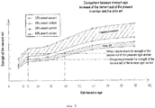
- the maintenance time for the cement soil strength of the cement-paste-pressure jet grouting cut-drilling segment to increase to the designed strength is reduced.
- the cement soil strength age of the silty clay increases.
- the strength of the cement soil can reach design requirements after 7-15 days, equivalent to the strength of the traditional jet spouting anchor after 28-50 days.
- the strength of the cement soil of the pressure-dispersion type bit expanded anchor of the present invention is far higher than the strength of the cement soil of the traditional jet spouting anchor.
- the anchor cable carrier is an anchor cable carrier fixed in the hardened cement soil in the cement-paste jet grouting cut-drilling segment 2;
- the anchor cables 3 are anchor cables provided with membranes;
- the anchor cable carriers are hinge type carriers or flat plate type carriers; when the anchor cable carriers are hinge type carriers, anchor cables 3 are coiled on the hinge type carriers in U-shape; and when the anchor cable carriers are flat plate type carriers, each flat plate type carrier is fixed with a fused anchor fixture for holding one end of an anchor cable 3.
- the anchor cable carrier and the anchor cables 3 are brought into the cement-paste jet grouting cut-drilling segment 2 in the non-jet-spouting state; a casing technology can be employed to bring the anchor cable carrier and the anchor cables 3 into the cement-paste jet grouting cut-drilling segment 2, or the drill rod can be used to bring the anchor cable carrier and the anchor cables 3 into the cement-paste jet grouting cut-drilling segment 2, etc.
- the anchor cable carrier is an anchor cable carrier fixed in the hardened cement soil in the cement-paste jet grouting cut-drilling segment 2; the anchor cables 3 are anchor cables provided with membranes; the anchor cable carriers are hinge type carriers or flat plate type carriers; when the anchor cable carriers are hinge type carriers, anchor cables 3 are coiled on the hinge type carriers in U-shape; and when the anchor cable carriers are flat plate type carriers, each flat plate type carrier is fixed with a fused anchor fixture for holding one end of an anchor cable 3.
- Technical solutions made by equivalent substitution shall all fall within the protective scope of the claims of the present invention.
Landscapes
- Engineering & Computer Science (AREA)
- Structural Engineering (AREA)
- Life Sciences & Earth Sciences (AREA)
- General Life Sciences & Earth Sciences (AREA)
- Mining & Mineral Resources (AREA)
- Paleontology (AREA)
- Civil Engineering (AREA)
- General Engineering & Computer Science (AREA)
- Piles And Underground Anchors (AREA)
Applications Claiming Priority (2)
| Application Number | Priority Date | Filing Date | Title |
|---|---|---|---|
| CN201410216623.2A CN104032737B (zh) | 2014-05-21 | 2014-05-21 | 压力分散型扩大头锚杆的施工方法及结构 |
| PCT/CN2015/078695 WO2015176614A1 (zh) | 2014-05-21 | 2015-05-11 | 压力分散型扩大头锚杆的施工方法及结构 |
Publications (3)
| Publication Number | Publication Date |
|---|---|
| EP3147410A1 true EP3147410A1 (de) | 2017-03-29 |
| EP3147410A4 EP3147410A4 (de) | 2017-04-12 |
| EP3147410B1 EP3147410B1 (de) | 2017-12-27 |
Family
ID=51463714
Family Applications (1)
| Application Number | Title | Priority Date | Filing Date |
|---|---|---|---|
| EP15795723.4A Not-in-force EP3147410B1 (de) | 2014-05-21 | 2015-05-11 | Konstruktionsverfahren und struktur für druckverteilenden expansionskopfankerstab |
Country Status (4)
| Country | Link |
|---|---|
| EP (1) | EP3147410B1 (de) |
| JP (1) | JP6285078B2 (de) |
| CN (1) | CN104032737B (de) |
| WO (1) | WO2015176614A1 (de) |
Cited By (1)
| Publication number | Priority date | Publication date | Assignee | Title |
|---|---|---|---|---|
| CN113585289A (zh) * | 2021-09-18 | 2021-11-02 | 中冶建工集团有限公司 | 塌陷性土质深基坑支护方法 |
Families Citing this family (69)
| Publication number | Priority date | Publication date | Assignee | Title |
|---|---|---|---|---|
| US8112871B2 (en) | 2009-09-28 | 2012-02-14 | Tyco Healthcare Group Lp | Method for manufacturing electrosurgical seal plates |
| US8512371B2 (en) | 2009-10-06 | 2013-08-20 | Covidien Lp | Jaw, blade and gap manufacturing for surgical instruments with small jaws |
| US8597295B2 (en) | 2010-04-12 | 2013-12-03 | Covidien Lp | Surgical instrument with non-contact electrical coupling |
| US8469991B2 (en) | 2010-06-02 | 2013-06-25 | Covidien Lp | Apparatus for performing an electrosurgical procedure |
| US8430877B2 (en) | 2010-06-02 | 2013-04-30 | Covidien Lp | Apparatus for performing an electrosurgical procedure |
| US8814864B2 (en) | 2010-08-23 | 2014-08-26 | Covidien Lp | Method of manufacturing tissue sealing electrodes |
| US8685009B2 (en) | 2011-05-16 | 2014-04-01 | Covidien Lp | Thread-like knife for tissue cutting |
| US8852185B2 (en) | 2011-05-19 | 2014-10-07 | Covidien Lp | Apparatus for performing an electrosurgical procedure |
| US8968283B2 (en) | 2011-05-19 | 2015-03-03 | Covidien Lp | Ultrasound device for precise tissue sealing and blade-less cutting |
| US9039732B2 (en) | 2011-07-11 | 2015-05-26 | Covidien Lp | Surgical forceps |
| US8864795B2 (en) | 2011-10-03 | 2014-10-21 | Covidien Lp | Surgical forceps |
| US9492221B2 (en) | 2011-10-20 | 2016-11-15 | Covidien Lp | Dissection scissors on surgical device |
| US8968310B2 (en) | 2011-11-30 | 2015-03-03 | Covidien Lp | Electrosurgical instrument with a knife blade lockout mechanism |
| US9113897B2 (en) | 2012-01-23 | 2015-08-25 | Covidien Lp | Partitioned surgical instrument |
| US8968360B2 (en) | 2012-01-25 | 2015-03-03 | Covidien Lp | Surgical instrument with resilient driving member and related methods of use |
| US9375282B2 (en) | 2012-03-26 | 2016-06-28 | Covidien Lp | Light energy sealing, cutting and sensing surgical device |
| US9820765B2 (en) | 2012-05-01 | 2017-11-21 | Covidien Lp | Surgical instrument with stamped double-flange jaws |
| US9113901B2 (en) | 2012-05-14 | 2015-08-25 | Covidien Lp | Modular surgical instrument with contained electrical or mechanical systems |
| US9301798B2 (en) | 2012-07-19 | 2016-04-05 | Covidien Lp | Surgical forceps including reposable end effector assemblies |
| US9681908B2 (en) | 2012-10-08 | 2017-06-20 | Covidien Lp | Jaw assemblies for electrosurgical instruments and methods of manufacturing jaw assemblies |
| US9526564B2 (en) | 2012-10-08 | 2016-12-27 | Covidien Lp | Electric stapler device |
| US9375259B2 (en) | 2012-10-24 | 2016-06-28 | Covidien Lp | Electrosurgical instrument including an adhesive applicator assembly |
| US9572529B2 (en) | 2012-10-31 | 2017-02-21 | Covidien Lp | Surgical devices and methods utilizing optical coherence tomography (OCT) to monitor and control tissue sealing |
| US9375205B2 (en) | 2012-11-15 | 2016-06-28 | Covidien Lp | Deployment mechanisms for surgical instruments |
| US9498281B2 (en) | 2012-11-27 | 2016-11-22 | Covidien Lp | Surgical apparatus |
| US9713491B2 (en) | 2013-02-19 | 2017-07-25 | Covidien Lp | Method for manufacturing an electrode assembly configured for use with an electrosurigcal instrument |
| US9456863B2 (en) | 2013-03-11 | 2016-10-04 | Covidien Lp | Surgical instrument with switch activation control |
| US9655673B2 (en) | 2013-03-11 | 2017-05-23 | Covidien Lp | Surgical instrument |
| US10070916B2 (en) | 2013-03-11 | 2018-09-11 | Covidien Lp | Surgical instrument with system and method for springing open jaw members |
| US9649151B2 (en) | 2013-05-31 | 2017-05-16 | Covidien Lp | End effector assemblies and methods of manufacturing end effector assemblies for treating and/or cutting tissue |
| EP3488805A1 (de) | 2013-08-07 | 2019-05-29 | Covidien LP | Bipolares chirurgisches instrument |
| US9445865B2 (en) | 2013-09-16 | 2016-09-20 | Covidien Lp | Electrosurgical instrument with end-effector assembly including electrically-conductive, tissue-engaging surfaces and switchable bipolar electrodes |
| US9943357B2 (en) | 2013-09-16 | 2018-04-17 | Covidien Lp | Split electrode for use in a bipolar electrosurgical instrument |
| US9687295B2 (en) | 2014-04-17 | 2017-06-27 | Covidien Lp | Methods of manufacturing a pair of jaw members of an end-effector assembly for a surgical instrument |
| US20150324317A1 (en) | 2014-05-07 | 2015-11-12 | Covidien Lp | Authentication and information system for reusable surgical instruments |
| CN104032737B (zh) * | 2014-05-21 | 2016-05-04 | 苏州市能工基础工程有限责任公司 | 压力分散型扩大头锚杆的施工方法及结构 |
| US10080606B2 (en) | 2014-09-17 | 2018-09-25 | Covidien Lp | Method of forming a member of an end effector |
| CN106498943B (zh) * | 2015-09-08 | 2019-03-05 | 宏润建设集团股份有限公司 | 一次性高压旋喷型扩大头预应力土锚杆施工方法 |
| US10631887B2 (en) | 2016-08-15 | 2020-04-28 | Covidien Lp | Electrosurgical forceps for video assisted thoracoscopic surgery and other surgical procedures |
| US10813695B2 (en) | 2017-01-27 | 2020-10-27 | Covidien Lp | Reflectors for optical-based vessel sealing |
| US10973567B2 (en) | 2017-05-12 | 2021-04-13 | Covidien Lp | Electrosurgical forceps for grasping, treating, and/or dividing tissue |
| US11172980B2 (en) | 2017-05-12 | 2021-11-16 | Covidien Lp | Electrosurgical forceps for grasping, treating, and/or dividing tissue |
| CN107143358B (zh) * | 2017-06-28 | 2024-04-09 | 山东省地质矿产勘查开发局八0一水文地质工程地质大队(山东省地矿工程勘察院) | 控制隧道偏压变形的对拉锚索结构及其施工方法 |
| CN107513996A (zh) * | 2017-10-20 | 2017-12-26 | 上海智平基础工程有限公司 | 一种可回收预应力锚索的锚具及其施工方法 |
| US11109930B2 (en) | 2018-06-08 | 2021-09-07 | Covidien Lp | Enhanced haptic feedback system |
| US11471211B2 (en) | 2018-10-12 | 2022-10-18 | Covidien Lp | Electrosurgical forceps |
| CN109322623A (zh) * | 2018-10-19 | 2019-02-12 | 广州市第二建筑工程有限公司 | 一种大直径旋喷桩的桩机设备及施工方法 |
| US11147613B2 (en) | 2019-03-15 | 2021-10-19 | Covidien Lp | Surgical instrument with increased lever stroke |
| US11523861B2 (en) | 2019-03-22 | 2022-12-13 | Covidien Lp | Methods for manufacturing a jaw assembly for an electrosurgical forceps |
| US11490916B2 (en) | 2019-03-29 | 2022-11-08 | Covidien Lp | Engagement features and methods for attaching a drive rod to a knife blade in an articulating surgical instrument |
| US11576696B2 (en) | 2019-03-29 | 2023-02-14 | Covidien Lp | Engagement features and methods for attaching a drive rod to a knife blade in an articulating surgical instrument |
| CN110055974A (zh) * | 2019-04-24 | 2019-07-26 | 兰州理工大学 | 一种可回收微型钢管桩土钉组合支护结构及其回收方法 |
| CN110792088B (zh) * | 2019-12-12 | 2024-12-13 | 中国电建集团昆明勘测设计研究院有限公司 | 一种变形可调锚拉桩阻滑结构及其阻滑方法 |
| CN110965551B (zh) * | 2019-12-26 | 2024-12-10 | 姚炳祥 | 一种可回收中心型锚索及其使用方法 |
| CN111021368A (zh) * | 2019-12-31 | 2020-04-17 | 陕西建工集团股份有限公司 | 一种拉森钢板和预应力钢束复合桩结构及其施工方法 |
| CN111560952A (zh) * | 2019-12-31 | 2020-08-21 | 刘晓理 | 伞状扩体装置与易切削锚杆或可回收锚杆索的融合结构 |
| US11622804B2 (en) | 2020-03-16 | 2023-04-11 | Covidien Lp | Forceps with linear trigger mechanism |
| CN111535314B (zh) * | 2020-06-03 | 2024-12-13 | 江苏东合南岩土科技股份有限公司 | 一种可回收锚杆及其施工方法 |
| CN111809620B (zh) * | 2020-06-28 | 2025-03-21 | 中国铁道科学研究院集团有限公司铁道建筑研究所 | 一种预应力钢锚管锚索张拉装置 |
| CN111852527B (zh) * | 2020-06-30 | 2025-02-21 | 焦作市倍特矿业设备有限公司 | 一种高强度锚索定位承载托盘及使用方法 |
| CN113323031A (zh) * | 2021-05-17 | 2021-08-31 | 宇旺建工集团有限公司 | 一种高压旋喷及布袋扩体抗浮锚杆施工工法 |
| CN113529709A (zh) * | 2021-08-13 | 2021-10-22 | 深圳百勤建设工程有限公司 | 一种压力型锚杆施工方法及压力型锚杆 |
| CN113931179A (zh) * | 2021-10-27 | 2022-01-14 | 贵州建工集团第一建筑工程有限责任公司 | 锚索成孔及注浆施工工法 |
| CN113914313A (zh) * | 2021-10-27 | 2022-01-11 | 贵州建工集团第一建筑工程有限责任公司 | 复杂地质条件下有限深度锚索施工工法 |
| CN114435538B (zh) * | 2022-01-26 | 2023-05-05 | 南京林业大学 | 一种反拉脱壳增长式鱼雷锚的装置与方法 |
| CN114547806B (zh) * | 2022-03-03 | 2024-05-03 | 中国地质科学院探矿工艺研究所 | 一种考虑锚岩相互作用的自承载式锚索设计方法 |
| CN115613565A (zh) * | 2022-11-12 | 2023-01-17 | 北京中润宝成工程技术有限公司 | 一种富含砂地层水下锚杆施工方法 |
| CN117127601A (zh) * | 2023-02-03 | 2023-11-28 | 中交第三航务工程局有限公司 | 一种锚杆初步施工方法 |
| CN117449295B (zh) * | 2023-10-27 | 2026-02-27 | 重庆达力索缆科技有限公司 | 一种压力分散型边坡锚索及其参数设计方法 |
Family Cites Families (17)
| Publication number | Priority date | Publication date | Assignee | Title |
|---|---|---|---|---|
| US2403643A (en) * | 1944-02-25 | 1946-07-09 | George L Dresser | Method of and apparatus for introducing grout into subsoil |
| DE1922744A1 (de) * | 1969-05-03 | 1970-11-05 | Mueller Ludwig | Vorrichtung zur Herstellung eines Hohlraumes in einem Baugrund mit stark unterschiedlichen Bodenschichten fuer Pfahlgruendungs- oder verankerungszwecke |
| DE3824955A1 (de) * | 1988-07-22 | 1990-01-25 | Gkn Keller Gmbh | Verfahren zum herstellen von bodenankern |
| US5203127A (en) * | 1991-06-28 | 1993-04-20 | Olthoff John R | Earth anchor |
| CA2088287C (en) * | 1992-02-07 | 2003-05-20 | Masaru Tateyama | Reinforcing block for excavation work and method of construction thereof |
| JP2804236B2 (ja) * | 1994-12-14 | 1998-09-24 | 東興建設株式会社 | アンカーの施工方法及びその装置 |
| JP3103038B2 (ja) * | 1996-11-29 | 2000-10-23 | 構造工事株式会社 | 拡底アンカー工法 |
| JP2000345560A (ja) * | 1999-06-07 | 2000-12-12 | Hiromitsu Utsunomiya | グランドアンカーの構築構造及びその構築方法 |
| JP3904779B2 (ja) * | 1999-11-15 | 2007-04-11 | 鉱研工業株式会社 | 地盤改良型アンカー工法および地盤改良兼用型削孔機 |
| NL1015346C2 (nl) * | 2000-05-31 | 2001-12-03 | Visser & Smit Bouw Bv | Werkwijze voor het verwijderen van de vrije ankerlengte van een in de grond aangebracht groutanker, alsmede een groutanker voor het uitvoeren van deze werkwijze. |
| JP4591878B2 (ja) * | 2004-02-10 | 2010-12-01 | 株式会社複合技術研究所 | 既設擁壁の補強構造および既設擁壁の補強工法 |
| CN100371533C (zh) * | 2005-07-19 | 2008-02-27 | 曾庆义 | 高压喷射扩大头锚杆的施工方法和装置 |
| CN101575854B (zh) * | 2009-06-10 | 2010-10-20 | 陕西中机岩土工程有限责任公司 | 一种高压旋喷扩大头锚杆及其施工方法 |
| CN203530988U (zh) * | 2013-08-12 | 2014-04-09 | 中国建筑第四工程局有限公司 | 一次成型大直径锚杆基坑支护结构 |
| CN103526754A (zh) * | 2013-09-30 | 2014-01-22 | 中国建筑第八工程局有限公司 | 一种富砂风化岩中扩大头锚杆的施工方法 |
| CN104032737B (zh) * | 2014-05-21 | 2016-05-04 | 苏州市能工基础工程有限责任公司 | 压力分散型扩大头锚杆的施工方法及结构 |
| CN203866824U (zh) * | 2014-05-21 | 2014-10-08 | 苏州市能工基础工程有限责任公司 | 压力分散型扩大头锚杆的结构 |
-
2014
- 2014-05-21 CN CN201410216623.2A patent/CN104032737B/zh active Active
-
2015
- 2015-05-11 JP JP2017513296A patent/JP6285078B2/ja not_active Expired - Fee Related
- 2015-05-11 WO PCT/CN2015/078695 patent/WO2015176614A1/zh not_active Ceased
- 2015-05-11 EP EP15795723.4A patent/EP3147410B1/de not_active Not-in-force
Cited By (1)
| Publication number | Priority date | Publication date | Assignee | Title |
|---|---|---|---|---|
| CN113585289A (zh) * | 2021-09-18 | 2021-11-02 | 中冶建工集团有限公司 | 塌陷性土质深基坑支护方法 |
Also Published As
| Publication number | Publication date |
|---|---|
| JP6285078B2 (ja) | 2018-02-28 |
| CN104032737B (zh) | 2016-05-04 |
| EP3147410B1 (de) | 2017-12-27 |
| CN104032737A (zh) | 2014-09-10 |
| JP2017516936A (ja) | 2017-06-22 |
| WO2015176614A1 (zh) | 2015-11-26 |
| EP3147410A4 (de) | 2017-04-12 |
Similar Documents
| Publication | Publication Date | Title |
|---|---|---|
| EP3147410A1 (de) | Konstruktionsverfahren und struktur für druckdispergierenden expansionskopfankerstab | |
| US8931236B2 (en) | System for anchoring a load | |
| CN103147440B (zh) | 预应力锚索施工方法 | |
| CN113217059B (zh) | 一种带预应力杆芯的组合锚杆 | |
| CN201704689U (zh) | 用于岩质边坡加固的四角加筋式预应力锚索锚头 | |
| CN104929117B (zh) | 一种混凝土杆身复合锚杆的施工方法 | |
| CN105201514A (zh) | 一种含水岩层井壁结构及施工方法 | |
| CN204959745U (zh) | 一种混凝土杆身复合锚杆 | |
| CN102345292B (zh) | 一种带有扩大头的复合预应力抗拔桩 | |
| CN104727317B (zh) | 一种减小锚索预应力损失的组合结构 | |
| CN109944241B (zh) | 锚索孔底反向牵拉装置及锚索安装方法 | |
| CN104120717B (zh) | 一种快速预应力锚索 | |
| CN203403359U (zh) | 箱梁中使用的一种竖向预应力钢棒螺纹锚具 | |
| EP2893139B1 (de) | Anordnung zur hochfesten verankerung eines einen spannstab aufweisenden spannglieds in einem bauteil sowie verfahren zur herstellung einer solchen verankerung | |
| CN203429632U (zh) | 拉压分散型锚索 | |
| CN205062813U (zh) | 一种可回收式锚索的锚具 | |
| CN202194130U (zh) | 一种带有扩大头的复合预应力抗拔桩 | |
| KR101853185B1 (ko) | 주면마찰력 향상을 위한 말뚝 그라우팅 장치 | |
| CN205529907U (zh) | 固定端p型锚具 | |
| EP3336258B1 (de) | Endverankerung für einen boden- und/oder felsanker | |
| CN203866824U (zh) | 压力分散型扩大头锚杆的结构 | |
| CN209227902U (zh) | 装配式混凝土结构柱钢管套筒节点 | |
| CN206916740U (zh) | 一种山地松散回填区抗沉陷预应力锚固结构 | |
| CN204898667U (zh) | 一种用于预应力复合杆索锚固体系的锚索定位导向装置 | |
| CN208816155U (zh) | 破碎围岩巷道支护用的预应力注浆锚索 |
Legal Events
| Date | Code | Title | Description |
|---|---|---|---|
| STAA | Information on the status of an ep patent application or granted ep patent |
Free format text: STATUS: THE INTERNATIONAL PUBLICATION HAS BEEN MADE |
|
| PUAI | Public reference made under article 153(3) epc to a published international application that has entered the european phase |
Free format text: ORIGINAL CODE: 0009012 |
|
| STAA | Information on the status of an ep patent application or granted ep patent |
Free format text: STATUS: REQUEST FOR EXAMINATION WAS MADE |
|
| 17P | Request for examination filed |
Effective date: 20161221 |
|
| AK | Designated contracting states |
Kind code of ref document: A1 Designated state(s): AL AT BE BG CH CY CZ DE DK EE ES FI FR GB GR HR HU IE IS IT LI LT LU LV MC MK MT NL NO PL PT RO RS SE SI SK SM TR |
|
| AX | Request for extension of the european patent |
Extension state: BA ME |
|
| A4 | Supplementary search report drawn up and despatched |
Effective date: 20170310 |
|
| RIC1 | Information provided on ipc code assigned before grant |
Ipc: E02D 5/74 20060101AFI20170306BHEP Ipc: E02D 5/80 20060101ALI20170306BHEP |
|
| GRAP | Despatch of communication of intention to grant a patent |
Free format text: ORIGINAL CODE: EPIDOSNIGR1 |
|
| STAA | Information on the status of an ep patent application or granted ep patent |
Free format text: STATUS: GRANT OF PATENT IS INTENDED |
|
| DAV | Request for validation of the european patent (deleted) | ||
| DAX | Request for extension of the european patent (deleted) | ||
| INTG | Intention to grant announced |
Effective date: 20170804 |
|
| GRAS | Grant fee paid |
Free format text: ORIGINAL CODE: EPIDOSNIGR3 |
|
| GRAA | (expected) grant |
Free format text: ORIGINAL CODE: 0009210 |
|
| STAA | Information on the status of an ep patent application or granted ep patent |
Free format text: STATUS: THE PATENT HAS BEEN GRANTED |
|
| AK | Designated contracting states |
Kind code of ref document: B1 Designated state(s): AL AT BE BG CH CY CZ DE DK EE ES FI FR GB GR HR HU IE IS IT LI LT LU LV MC MK MT NL NO PL PT RO RS SE SI SK SM TR |
|
| REG | Reference to a national code |
Ref country code: GB Ref legal event code: FG4D |
|
| REG | Reference to a national code |
Ref country code: CH Ref legal event code: EP |
|
| REG | Reference to a national code |
Ref country code: AT Ref legal event code: REF Ref document number: 958412 Country of ref document: AT Kind code of ref document: T Effective date: 20180115 |
|
| REG | Reference to a national code |
Ref country code: IE Ref legal event code: FG4D |
|
| REG | Reference to a national code |
Ref country code: DE Ref legal event code: R096 Ref document number: 602015007055 Country of ref document: DE |
|
| PG25 | Lapsed in a contracting state [announced via postgrant information from national office to epo] |
Ref country code: LT Free format text: LAPSE BECAUSE OF FAILURE TO SUBMIT A TRANSLATION OF THE DESCRIPTION OR TO PAY THE FEE WITHIN THE PRESCRIBED TIME-LIMIT Effective date: 20171227 Ref country code: NO Free format text: LAPSE BECAUSE OF FAILURE TO SUBMIT A TRANSLATION OF THE DESCRIPTION OR TO PAY THE FEE WITHIN THE PRESCRIBED TIME-LIMIT Effective date: 20180327 Ref country code: FI Free format text: LAPSE BECAUSE OF FAILURE TO SUBMIT A TRANSLATION OF THE DESCRIPTION OR TO PAY THE FEE WITHIN THE PRESCRIBED TIME-LIMIT Effective date: 20171227 |
|
| REG | Reference to a national code |
Ref country code: NL Ref legal event code: MP Effective date: 20171227 |
|
| REG | Reference to a national code |
Ref country code: LT Ref legal event code: MG4D |
|
| REG | Reference to a national code |
Ref country code: AT Ref legal event code: MK05 Ref document number: 958412 Country of ref document: AT Kind code of ref document: T Effective date: 20171227 |
|
| PG25 | Lapsed in a contracting state [announced via postgrant information from national office to epo] |
Ref country code: BG Free format text: LAPSE BECAUSE OF FAILURE TO SUBMIT A TRANSLATION OF THE DESCRIPTION OR TO PAY THE FEE WITHIN THE PRESCRIBED TIME-LIMIT Effective date: 20180327 Ref country code: RS Free format text: LAPSE BECAUSE OF FAILURE TO SUBMIT A TRANSLATION OF THE DESCRIPTION OR TO PAY THE FEE WITHIN THE PRESCRIBED TIME-LIMIT Effective date: 20171227 Ref country code: LV Free format text: LAPSE BECAUSE OF FAILURE TO SUBMIT A TRANSLATION OF THE DESCRIPTION OR TO PAY THE FEE WITHIN THE PRESCRIBED TIME-LIMIT Effective date: 20171227 Ref country code: HR Free format text: LAPSE BECAUSE OF FAILURE TO SUBMIT A TRANSLATION OF THE DESCRIPTION OR TO PAY THE FEE WITHIN THE PRESCRIBED TIME-LIMIT Effective date: 20171227 Ref country code: GR Free format text: LAPSE BECAUSE OF FAILURE TO SUBMIT A TRANSLATION OF THE DESCRIPTION OR TO PAY THE FEE WITHIN THE PRESCRIBED TIME-LIMIT Effective date: 20180328 |
|
| PG25 | Lapsed in a contracting state [announced via postgrant information from national office to epo] |
Ref country code: NL Free format text: LAPSE BECAUSE OF FAILURE TO SUBMIT A TRANSLATION OF THE DESCRIPTION OR TO PAY THE FEE WITHIN THE PRESCRIBED TIME-LIMIT Effective date: 20171227 |
|
| PG25 | Lapsed in a contracting state [announced via postgrant information from national office to epo] |
Ref country code: CZ Free format text: LAPSE BECAUSE OF FAILURE TO SUBMIT A TRANSLATION OF THE DESCRIPTION OR TO PAY THE FEE WITHIN THE PRESCRIBED TIME-LIMIT Effective date: 20171227 Ref country code: CY Free format text: LAPSE BECAUSE OF FAILURE TO SUBMIT A TRANSLATION OF THE DESCRIPTION OR TO PAY THE FEE WITHIN THE PRESCRIBED TIME-LIMIT Effective date: 20171227 Ref country code: EE Free format text: LAPSE BECAUSE OF FAILURE TO SUBMIT A TRANSLATION OF THE DESCRIPTION OR TO PAY THE FEE WITHIN THE PRESCRIBED TIME-LIMIT Effective date: 20171227 Ref country code: ES Free format text: LAPSE BECAUSE OF FAILURE TO SUBMIT A TRANSLATION OF THE DESCRIPTION OR TO PAY THE FEE WITHIN THE PRESCRIBED TIME-LIMIT Effective date: 20171227 Ref country code: SK Free format text: LAPSE BECAUSE OF FAILURE TO SUBMIT A TRANSLATION OF THE DESCRIPTION OR TO PAY THE FEE WITHIN THE PRESCRIBED TIME-LIMIT Effective date: 20171227 |
|
| PG25 | Lapsed in a contracting state [announced via postgrant information from national office to epo] |
Ref country code: SM Free format text: LAPSE BECAUSE OF FAILURE TO SUBMIT A TRANSLATION OF THE DESCRIPTION OR TO PAY THE FEE WITHIN THE PRESCRIBED TIME-LIMIT Effective date: 20171227 Ref country code: IS Free format text: LAPSE BECAUSE OF FAILURE TO SUBMIT A TRANSLATION OF THE DESCRIPTION OR TO PAY THE FEE WITHIN THE PRESCRIBED TIME-LIMIT Effective date: 20180427 Ref country code: AT Free format text: LAPSE BECAUSE OF FAILURE TO SUBMIT A TRANSLATION OF THE DESCRIPTION OR TO PAY THE FEE WITHIN THE PRESCRIBED TIME-LIMIT Effective date: 20171227 Ref country code: PL Free format text: LAPSE BECAUSE OF FAILURE TO SUBMIT A TRANSLATION OF THE DESCRIPTION OR TO PAY THE FEE WITHIN THE PRESCRIBED TIME-LIMIT Effective date: 20171227 |
|
| REG | Reference to a national code |
Ref country code: DE Ref legal event code: R097 Ref document number: 602015007055 Country of ref document: DE |
|
| PLBE | No opposition filed within time limit |
Free format text: ORIGINAL CODE: 0009261 |
|
| STAA | Information on the status of an ep patent application or granted ep patent |
Free format text: STATUS: NO OPPOSITION FILED WITHIN TIME LIMIT |
|
| PG25 | Lapsed in a contracting state [announced via postgrant information from national office to epo] |
Ref country code: DK Free format text: LAPSE BECAUSE OF FAILURE TO SUBMIT A TRANSLATION OF THE DESCRIPTION OR TO PAY THE FEE WITHIN THE PRESCRIBED TIME-LIMIT Effective date: 20171227 |
|
| 26N | No opposition filed |
Effective date: 20180928 |
|
| REG | Reference to a national code |
Ref country code: CH Ref legal event code: PL |
|
| REG | Reference to a national code |
Ref country code: BE Ref legal event code: MM Effective date: 20180531 |
|
| PG25 | Lapsed in a contracting state [announced via postgrant information from national office to epo] |
Ref country code: MC Free format text: LAPSE BECAUSE OF FAILURE TO SUBMIT A TRANSLATION OF THE DESCRIPTION OR TO PAY THE FEE WITHIN THE PRESCRIBED TIME-LIMIT Effective date: 20171227 |
|
| REG | Reference to a national code |
Ref country code: IE Ref legal event code: MM4A |
|
| PG25 | Lapsed in a contracting state [announced via postgrant information from national office to epo] |
Ref country code: CH Free format text: LAPSE BECAUSE OF NON-PAYMENT OF DUE FEES Effective date: 20180531 Ref country code: LI Free format text: LAPSE BECAUSE OF NON-PAYMENT OF DUE FEES Effective date: 20180531 |
|
| PG25 | Lapsed in a contracting state [announced via postgrant information from national office to epo] |
Ref country code: LU Free format text: LAPSE BECAUSE OF NON-PAYMENT OF DUE FEES Effective date: 20180511 |
|
| PG25 | Lapsed in a contracting state [announced via postgrant information from national office to epo] |
Ref country code: FR Free format text: LAPSE BECAUSE OF NON-PAYMENT OF DUE FEES Effective date: 20180531 Ref country code: IE Free format text: LAPSE BECAUSE OF NON-PAYMENT OF DUE FEES Effective date: 20180511 |
|
| PG25 | Lapsed in a contracting state [announced via postgrant information from national office to epo] |
Ref country code: BE Free format text: LAPSE BECAUSE OF NON-PAYMENT OF DUE FEES Effective date: 20180531 |
|
| PG25 | Lapsed in a contracting state [announced via postgrant information from national office to epo] |
Ref country code: MT Free format text: LAPSE BECAUSE OF NON-PAYMENT OF DUE FEES Effective date: 20180511 |
|
| PG25 | Lapsed in a contracting state [announced via postgrant information from national office to epo] |
Ref country code: TR Free format text: LAPSE BECAUSE OF FAILURE TO SUBMIT A TRANSLATION OF THE DESCRIPTION OR TO PAY THE FEE WITHIN THE PRESCRIBED TIME-LIMIT Effective date: 20171227 |
|
| PG25 | Lapsed in a contracting state [announced via postgrant information from national office to epo] |
Ref country code: PT Free format text: LAPSE BECAUSE OF FAILURE TO SUBMIT A TRANSLATION OF THE DESCRIPTION OR TO PAY THE FEE WITHIN THE PRESCRIBED TIME-LIMIT Effective date: 20171227 |
|
| PG25 | Lapsed in a contracting state [announced via postgrant information from national office to epo] |
Ref country code: MK Free format text: LAPSE BECAUSE OF NON-PAYMENT OF DUE FEES Effective date: 20171227 Ref country code: HU Free format text: LAPSE BECAUSE OF FAILURE TO SUBMIT A TRANSLATION OF THE DESCRIPTION OR TO PAY THE FEE WITHIN THE PRESCRIBED TIME-LIMIT; INVALID AB INITIO Effective date: 20150511 Ref country code: SE Free format text: LAPSE BECAUSE OF FAILURE TO SUBMIT A TRANSLATION OF THE DESCRIPTION OR TO PAY THE FEE WITHIN THE PRESCRIBED TIME-LIMIT Effective date: 20171227 Ref country code: RO Free format text: LAPSE BECAUSE OF FAILURE TO SUBMIT A TRANSLATION OF THE DESCRIPTION OR TO PAY THE FEE WITHIN THE PRESCRIBED TIME-LIMIT Effective date: 20171227 |
|
| PG25 | Lapsed in a contracting state [announced via postgrant information from national office to epo] |
Ref country code: AL Free format text: LAPSE BECAUSE OF FAILURE TO SUBMIT A TRANSLATION OF THE DESCRIPTION OR TO PAY THE FEE WITHIN THE PRESCRIBED TIME-LIMIT Effective date: 20171227 |
|
| PG25 | Lapsed in a contracting state [announced via postgrant information from national office to epo] |
Ref country code: SI Free format text: LAPSE BECAUSE OF NON-PAYMENT OF DUE FEES Effective date: 20180511 |
|
| PGFP | Annual fee paid to national office [announced via postgrant information from national office to epo] |
Ref country code: GB Payment date: 20211124 Year of fee payment: 7 Ref country code: DE Payment date: 20211124 Year of fee payment: 7 |
|
| PGFP | Annual fee paid to national office [announced via postgrant information from national office to epo] |
Ref country code: IT Payment date: 20211126 Year of fee payment: 7 |
|
| REG | Reference to a national code |
Ref country code: DE Ref legal event code: R119 Ref document number: 602015007055 Country of ref document: DE |
|
| GBPC | Gb: european patent ceased through non-payment of renewal fee |
Effective date: 20220511 |
|
| PG25 | Lapsed in a contracting state [announced via postgrant information from national office to epo] |
Ref country code: GB Free format text: LAPSE BECAUSE OF NON-PAYMENT OF DUE FEES Effective date: 20220511 Ref country code: DE Free format text: LAPSE BECAUSE OF NON-PAYMENT OF DUE FEES Effective date: 20221201 |
|
| PG25 | Lapsed in a contracting state [announced via postgrant information from national office to epo] |
Ref country code: IT Free format text: LAPSE BECAUSE OF NON-PAYMENT OF DUE FEES Effective date: 20220511 |