EP3147437B1 - Élement de logement de paumelle pour un systeme de paumelle invisible pour portes ou fenetres et paumelle de porte comprenant un element de logement de paumelle - Google Patents
Élement de logement de paumelle pour un systeme de paumelle invisible pour portes ou fenetres et paumelle de porte comprenant un element de logement de paumelle Download PDFInfo
- Publication number
- EP3147437B1 EP3147437B1 EP16185524.2A EP16185524A EP3147437B1 EP 3147437 B1 EP3147437 B1 EP 3147437B1 EP 16185524 A EP16185524 A EP 16185524A EP 3147437 B1 EP3147437 B1 EP 3147437B1
- Authority
- EP
- European Patent Office
- Prior art keywords
- hinge
- receiving
- door
- bearing
- piece
- Prior art date
- Legal status (The legal status is an assumption and is not a legal conclusion. Google has not performed a legal analysis and makes no representation as to the accuracy of the status listed.)
- Active
Links
Images

Classifications
-
- E—FIXED CONSTRUCTIONS
- E05—LOCKS; KEYS; WINDOW OR DOOR FITTINGS; SAFES
- E05D—HINGES OR SUSPENSION DEVICES FOR DOORS, WINDOWS OR WINGS
- E05D3/00—Hinges with pins
- E05D3/06—Hinges with pins with two or more pins
- E05D3/18—Hinges with pins with two or more pins with sliding pins or guides
- E05D3/186—Scissors hinges, with two crossing levers and five parallel pins
-
- E—FIXED CONSTRUCTIONS
- E05—LOCKS; KEYS; WINDOW OR DOOR FITTINGS; SAFES
- E05D—HINGES OR SUSPENSION DEVICES FOR DOORS, WINDOWS OR WINGS
- E05D7/00—Hinges or pivots of special construction
- E05D7/04—Hinges adjustable relative to the wing or the frame
-
- E—FIXED CONSTRUCTIONS
- E05—LOCKS; KEYS; WINDOW OR DOOR FITTINGS; SAFES
- E05D—HINGES OR SUSPENSION DEVICES FOR DOORS, WINDOWS OR WINGS
- E05D7/00—Hinges or pivots of special construction
- E05D7/04—Hinges adjustable relative to the wing or the frame
- E05D7/0415—Hinges adjustable relative to the wing or the frame with adjusting drive means
-
- E—FIXED CONSTRUCTIONS
- E05—LOCKS; KEYS; WINDOW OR DOOR FITTINGS; SAFES
- E05D—HINGES OR SUSPENSION DEVICES FOR DOORS, WINDOWS OR WINGS
- E05D7/00—Hinges or pivots of special construction
- E05D7/04—Hinges adjustable relative to the wing or the frame
- E05D2007/0469—Hinges adjustable relative to the wing or the frame in an axial direction
-
- E—FIXED CONSTRUCTIONS
- E05—LOCKS; KEYS; WINDOW OR DOOR FITTINGS; SAFES
- E05D—HINGES OR SUSPENSION DEVICES FOR DOORS, WINDOWS OR WINGS
- E05D7/00—Hinges or pivots of special construction
- E05D7/04—Hinges adjustable relative to the wing or the frame
- E05D2007/0476—Pocket hinges
-
- E—FIXED CONSTRUCTIONS
- E05—LOCKS; KEYS; WINDOW OR DOOR FITTINGS; SAFES
- E05D—HINGES OR SUSPENSION DEVICES FOR DOORS, WINDOWS OR WINGS
- E05D7/00—Hinges or pivots of special construction
- E05D7/04—Hinges adjustable relative to the wing or the frame
- E05D2007/0484—Hinges adjustable relative to the wing or the frame in a radial direction
-
- E—FIXED CONSTRUCTIONS
- E05—LOCKS; KEYS; WINDOW OR DOOR FITTINGS; SAFES
- E05D—HINGES OR SUSPENSION DEVICES FOR DOORS, WINDOWS OR WINGS
- E05D7/00—Hinges or pivots of special construction
- E05D7/04—Hinges adjustable relative to the wing or the frame
- E05D2007/0492—Hinges adjustable relative to the wing or the frame in three directions
-
- E—FIXED CONSTRUCTIONS
- E05—LOCKS; KEYS; WINDOW OR DOOR FITTINGS; SAFES
- E05Y—INDEXING SCHEME ASSOCIATED WITH SUBCLASSES E05D AND E05F, RELATING TO CONSTRUCTION ELEMENTS, ELECTRIC CONTROL, POWER SUPPLY, POWER SIGNAL OR TRANSMISSION, USER INTERFACES, MOUNTING OR COUPLING, DETAILS, ACCESSORIES, AUXILIARY OPERATIONS NOT OTHERWISE PROVIDED FOR, APPLICATION THEREOF
- E05Y2201/00—Constructional elements; Accessories therefor
- E05Y2201/60—Suspension or transmission members; Accessories therefor
- E05Y2201/622—Suspension or transmission members elements
- E05Y2201/71—Toothed gearing
- E05Y2201/716—Pinions
-
- E—FIXED CONSTRUCTIONS
- E05—LOCKS; KEYS; WINDOW OR DOOR FITTINGS; SAFES
- E05Y—INDEXING SCHEME ASSOCIATED WITH SUBCLASSES E05D AND E05F, RELATING TO CONSTRUCTION ELEMENTS, ELECTRIC CONTROL, POWER SUPPLY, POWER SIGNAL OR TRANSMISSION, USER INTERFACES, MOUNTING OR COUPLING, DETAILS, ACCESSORIES, AUXILIARY OPERATIONS NOT OTHERWISE PROVIDED FOR, APPLICATION THEREOF
- E05Y2201/00—Constructional elements; Accessories therefor
- E05Y2201/60—Suspension or transmission members; Accessories therefor
- E05Y2201/622—Suspension or transmission members elements
- E05Y2201/71—Toothed gearing
- E05Y2201/722—Racks
-
- E—FIXED CONSTRUCTIONS
- E05—LOCKS; KEYS; WINDOW OR DOOR FITTINGS; SAFES
- E05Y—INDEXING SCHEME ASSOCIATED WITH SUBCLASSES E05D AND E05F, RELATING TO CONSTRUCTION ELEMENTS, ELECTRIC CONTROL, POWER SUPPLY, POWER SIGNAL OR TRANSMISSION, USER INTERFACES, MOUNTING OR COUPLING, DETAILS, ACCESSORIES, AUXILIARY OPERATIONS NOT OTHERWISE PROVIDED FOR, APPLICATION THEREOF
- E05Y2600/00—Mounting or coupling arrangements for elements provided for in this subclass
- E05Y2600/40—Mounting location; Visibility of the elements
- E05Y2600/41—Concealed
-
- E—FIXED CONSTRUCTIONS
- E05—LOCKS; KEYS; WINDOW OR DOOR FITTINGS; SAFES
- E05Y—INDEXING SCHEME ASSOCIATED WITH SUBCLASSES E05D AND E05F, RELATING TO CONSTRUCTION ELEMENTS, ELECTRIC CONTROL, POWER SUPPLY, POWER SIGNAL OR TRANSMISSION, USER INTERFACES, MOUNTING OR COUPLING, DETAILS, ACCESSORIES, AUXILIARY OPERATIONS NOT OTHERWISE PROVIDED FOR, APPLICATION THEREOF
- E05Y2900/00—Application of doors, windows, wings or fittings thereof
- E05Y2900/10—Application of doors, windows, wings or fittings thereof for buildings or parts thereof
- E05Y2900/13—Type of wing
- E05Y2900/132—Doors
-
- E—FIXED CONSTRUCTIONS
- E05—LOCKS; KEYS; WINDOW OR DOOR FITTINGS; SAFES
- E05Y—INDEXING SCHEME ASSOCIATED WITH SUBCLASSES E05D AND E05F, RELATING TO CONSTRUCTION ELEMENTS, ELECTRIC CONTROL, POWER SUPPLY, POWER SIGNAL OR TRANSMISSION, USER INTERFACES, MOUNTING OR COUPLING, DETAILS, ACCESSORIES, AUXILIARY OPERATIONS NOT OTHERWISE PROVIDED FOR, APPLICATION THEREOF
- E05Y2900/00—Application of doors, windows, wings or fittings thereof
- E05Y2900/10—Application of doors, windows, wings or fittings thereof for buildings or parts thereof
- E05Y2900/13—Type of wing
- E05Y2900/148—Windows
Definitions
- the invention relates to a tape receiving part for a concealed hinge system for doors or windows according to the preamble of claim 1.
- the invention also relates to a door hinge according to the preamble of additional claim. 9
- the tape receiving part is an essential component of the tape system. It is used in particular for door hinges, which are arranged completely concealed between the door frame and door leaf when the door is closed and are not visible on the outside of the door.
- the preferred field of application are doors for residential and office rooms as well as object doors or building entrance doors.
- the door leaves can have a large weight, so that the door hinges and their components must meet high demands on the dimensional stability and continuous load.
- the hinge system can also be used for windows and other building closures.
- the invention is based on the tape receiving part is adjustable in two axes. It allows both a vertical adjustment of the door relative to the frame and a Anyakver ein the door leaf. Both the vertical adjustment and the pressure adjustment of the door leaf are of essential importance for doors equipped with a concealed hinge system. For reasons of design, concealed hinge systems are often used on doors whose door leaves are flush with the door frame, leaving a shadow gap between the door leaf and the door frame.
- the door leaf must be adjustable so that the shadow gap along the entire circumference of the door leaf in the closed state has constant dimensions. Already slight deviations become optically perceived as extremely disturbing. Both the Anyakver ein the door leaf and the vertical adjustment of the door must therefore be possible with great precision. During adjustment, the entire weight of the door leaf must be absorbed by the belt construction, so that a precise adjustment succeeds. After adjustment, all mutually movable parts must be firmly connected to each other, so that the door does not move even with a continuous load.
- a tape receiving part for a concealed hinge system for doors which comprises a fastening piece for attachment to a frame or door, a receiving piece which is adjustably arranged in a receiving space of the fastening piece and a bearing insert for connection of hinge members, wherein a rotatable pinion with a Tooth profile meshes and thereby allows a horizontal adjustment of the bearing insert.
- a vertical adjustment of the door hinge is provided on a separate band part.
- a generic door hinge with a generic tape receiving part is made DE 20 2010 016 896 U1 known.
- CN 103 938 967 A describes the adjustment of tape receiving parts of a door hinge by pinion and a respective associated tooth profile.
- Out DE 102 39 446 C1 is another generic door hinge for a concealed arrangement between the door frame and door known.
- the known door hinge comprises a first hinge part and a second hinge part, which are interconnected by a multi-membered joint.
- the two band parts are in MontageausEnglishungen in the door frame and in a narrow side of the Door leaf can be used.
- Each of the two band parts has a fastening piece for attachment to a frame or a door leaf and bearing inserts for connection of joint members of a multi-link joint.
- the bearing inserts of the first hinge part are each vertically adjustable in a guide recess of the fastening piece.
- the bearing inserts of the other hinge part are arranged horizontally adjustable in the associated attachment piece. Adjustment eccentrics are provided for both horizontal adjustment and vertical adjustment.
- the disadvantage is that the vertical adjustment and the lateral adjustment of the door must be made to different hinge parts. The precision of the adjustment, in particular the Andruckver ein the door leaf, is still in need of improvement.
- the invention has for its object to provide a tape receiving part for a concealed hinge system, which allows a two-axis adjustment for vertical adjustment of the door leaf and Anyakver ein.
- the tape receiving part should allow precise Antikver ein the door or window sash and must be particularly suitable for heavy doors.
- Another aspect is the combination with a device for vertical adjustment of the door leaf, which allows a precise vertical adjustment while absorbing large loads.
- the invention and solution to this problem is a tape receiving element for a concealed hinge system for doors or windows with the features of claim 1.
- Advantageous embodiments of the tape receiving element are described in the subclaims 2 to 8.
- the tape receiving element comprises a fastening piece for attachment to a frame or a door or window sash, a receiving piece which is vertically adjustable in a receiving space of the Attachment is arranged, and a bearing insert for connection of hinge members of a multi-link joint.
- the bearing insert is horizontally adjustable arranged on the receiving piece and fixed by means of a screw on the receiving piece.
- the bearing insert has a rotatably arranged pinion, which meshes with a fixedly arranged on the receiving piece tooth profile and after loosening the screw allows horizontal adjustment of the bearing insert on the receiving piece.
- the bearing insert is suitably guided linearly movable on guide surfaces of the receiving part.
- guide surfaces are step surfaces or grooves, which cooperate with a mating surface or a projection.
- the screw connection is used to guide the bearing insert horizontally on the receiving piece.
- the screw connection between the bearing insert and the receiving piece on two screws, which pass through horizontally aligned slots of the bearing insert.
- the screw connection allows a firm and permanent connection between the bearing insert and the receiving piece.
- the pinion has on its freely accessible end face on a connection device for a turning tool.
- the receiving piece is formed as a die-cast part and has a projection on which the tooth profile is formed. At one of the tooth profile facing away from the back of the projection, a wedge surface is provided, acts on a Vertikalverstell Surprise.
- the pinion for Anyakver ein the bearing insert and the wedge surface, which is used for vertical adjustment of the receiving piece, are integrated to save space in the tape receiving part.
- the arrangement is characterized by a high dimensional stability.
- the vertical adjustment device has a wedge element which has a contact surface which is complementary to the wedge surface of the projection formed on the receiving piece and can be tensioned against the receiver piece by means of a clamping screw.
- the wedge surface and the complementary pressure surface expediently have an inclination angle of about 45 °.
- the adjusting movement of the clamping screw causes an offset movement of the wedge element and the integrally formed on the receiving piece wedge-shaped projection.
- the offset movement has a component of motion which causes vertical adjustment of the receiving piece.
- the wedge member is supported on a surface of the attachment piece.
- the receiving piece can be fixed by means of a screw on the attachment piece.
- the screw has at least one clamping screw, which passes through a vertically aligned slot of the receiving piece. After loosening the screw connection, the previously described vertical adjustment can be carried out. After setting the desired position, the receiving piece and the attachment piece can be firmly connected to each other by means of the screw.
- the bearing insert is preferably designed as a die-cast part and has a bearing opening for the pinion.
- the bearing opening encloses a circumferential Section of the pinion, which is preferably more than 180 °.
- the pinion may have a collar which engages behind a counter surface of the bearing insert and secures the pinion axially in the bearing opening.
- the bearing insert is matched to the structural design of the multi-jointed joint.
- An advantageous embodiment of the invention provides that the bearing insert has a groove for longitudinal guidance of a first joint member and a bearing bore for rotatably supporting a second joint member.
- the attachment piece may be formed as a die-cast part and preferably has the form of a housing which has an opening-side installation space for the receiving piece and the bearing insert.
- the invention also provides a door hinge for a concealed arrangement between the door frame and the door leaf with a first hinge part and a second hinge part, which are hinged together by a multi-membered joint.
- the two band parts can be used in MontageausEnglishept in the door frame and in a narrow side of the door leaf.
- the first hinge part which is preferably mounted in a recess of the door frame, has at its upper end and at its lower end in each case a tape receiving part, which has the structure described above.
- the hinge members of the multi-membered joint are mounted on the bearing inserts of the two band receiving parts.
- the bearing inserts of the two tape receiving parts are arranged on a support.
- This form the Attachment piece and arranged therein receiving piece of the two tape receiving parts separate and not connected to the carrier assemblies.
- the support may in particular be formed as a thin-walled shell, which has a bottom and at least one side wall, wherein the side wall bridges the distance between the bearing inserts and has a height corresponding to the depth of the mounting recess.
- the first hinge part has a housing which can be inserted into an associated mounting recess in the door frame or in the narrow side of the door leaf, and that the attachment pieces of the two tape receiving parts are components of the housing.
- the second band part may have an adjusting device, with which a bearing arrangement of the joint members of the multi-link joint in the depth direction of the mounting recess is horizontally adjustable.
- an adjustment of the second hinge part an adjustment of the door hinge in three axial directions is possible.
- the adjusting device of the second hinge part also allows a so-called lateral adjustment of the door leaf to adjust the door laterally.
- a door hinge for a concealed arrangement between the door frame and door leaf.
- the door hinge comprises a first hinge part 1, a second hinge part 2 and a multi-joint hinge 3 connecting the two hinge parts 1, 2.
- the two hinge parts 1, 2 can be inserted in mounting recesses in the door frame and in a narrow side of a door leaf.
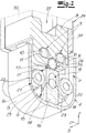
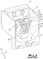
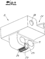
- the first hinge part 1 has at its upper end and at its lower end in each case a tape receiving part 4, which hereinafter with reference to FIG Fig. 2 to 4 is explained.
- tape receiving part 4 is intended for a concealed hinge system for doors or windows and includes a mounting piece 5 for attachment to a frame or a door or window sash, a receiving piece 6, which is arranged vertically adjustable in the z direction in a receiving space 7 of the fixing piece 5
- the bearing insert 8 is arranged in the x-direction horizontally adjustable on the receiving piece 6 and fixed by means of a screw 9 to the receiving piece 6, and a bearing insert 8 for connecting joint members of a multi-membered joint.
- the screw 9 between the bearing insert 8 and the receiving piece 6, two screws 10, the horizontally oriented slots 11 of the bearing insert 8 pass through. The screw 9 allows horizontal adjustment of the bearing insert 8 along the receiving piece 6 to adjust the pressure of the door leaf to a door seal.
- the receiving piece 6 is formed as a die-cast part and has as shown in the Fig. 2 and 3 a projection 12 on which a tooth profile 13 is formed.
- a wedge surface 14 is provided, acts on a vertical adjustment 15.
- the vertical adjustment device 15 has a wedge element 16, which has a contact surface 17 which is complementary to the wedge surface 14 of the projection 12 and can be tensioned against the receiving piece 6 by means of a clamping screw 18.
- the wedge surface 14 and its associated complementary pressure surface 17 are inclined at an angle of approximately 45 °.
- the clamping screw 18 passes through a slot-shaped opening 19 arranged in the wedge surface 14 of the projection 12, which permits the relative movement between the wedge element 16 and the receiving piece 6 necessary for the vertical adjustment of the receiving piece 6.
- the wedge member 16 is supported on a surface 20 of the attachment piece 5.
- the vertical adjustment of the receiving piece 6 is possible under load, wherein the wedge member 16 receives the transmitted via the articulated connection of the multi-unit joint 3 weight of the door leaf.
- the receiving piece 6 can be fixed by means of a screw 21 to the attachment piece 5.
- the screw 21 has at least one clamping screw 22 which engages a vertically aligned slot 23 of the receiving piece 6. In the embodiment and according to a preferred embodiment, two clamping screws 22 are provided.
- the bearing insert 8 has a rotatably arranged pinion 24, which meshes with the fixed to the receiving piece 6 tooth profile 13 and after loosening the screw 9 allows horizontal adjustment of the bearing insert 8 on the receiving piece 6.
- the bearing insert 8 has a bearing opening 25 for the pinion 24 and can be inexpensively manufactured as a die-cast part.
- the bearing opening 25 encloses a peripheral portion of the pinion 24, which is preferably more than 180 °.
- the storage of the pinion 24 is in the Fig. 2 and 4 shown. From the illustration it can be seen that the pinion 24 has a collar 26 which engages behind a mating surface of the bearing insert 8 and the pinion 24 axially secured in the bearing opening 25.
- the bearing insert 8 has a groove 27 for longitudinal guidance of a first joint member and a bearing bore 28 for rotatably supporting a second joint member.
- the attachment piece 5 can also be produced as a die-cast part and has the form of a housing which has a frontally open space as a receiving space 7 for the receiving piece 6 and the bearing insert 8.
- the first band part 1 of in Fig. 1 Door hinge shown has two tape receiving parts 4, the bearing inserts 8 are arranged on a support 29.
- the attachment piece 5 and the receiving piece 6 of the two strap receiving parts 4 arranged therein form separate and separate from the carrier 29 assemblies.
- the carrier 29 is formed as a thin-walled shell and has a bottom 30 and at least one side wall 31, which bridges the distance between the bearing inserts 8 and has a depth of the mounting recess corresponding height.
- the second band part 2 of in Fig. 1 shown door hinge comprises an adjusting device 32, with which a bearing arrangement of the hinge members of the multi-membered joint 3 in the depth direction of the mounting recess is horizontally adjustable.
- this adjusting device 32 By means of this adjusting device 32, the door can be adjusted laterally.
- the adjusting device 32 is therefore also referred to as adjustment for lateral adjustment.
Landscapes
- Engineering & Computer Science (AREA)
- Mechanical Engineering (AREA)
- Hinges (AREA)
Claims (13)
- Élément récepteur de paumelle (4) pour système de paumelle à positionnement masqué pour porte ou fenêtre, comportant
une pièce de fixation (5) destinée à être fixée à un encadrement ou à un battant de porte ou de fenêtre,
une pièce réceptrice (6) qui est disposée avec possibilité de réglage vertical dans un espace récepteur (7) de la pièce de fixation (5), et
une garniture d'appui (8) pour le raccordement d'éléments articulés d'une articulation à plusieurs éléments (3),
la garniture d'appui (8) étant disposée de manière à être réglable horizontalement au niveau de la pièce réceptrice (6) et pouvant être fixée au moyen d'un raccord vissé (9) à la pièce réceptrice (6), caractérisé en ce que la garniture d'appui (8) présente un pignon disposé de manière à pouvoir tourner (24) qui s'empeigne avec un profilé denté (13) disposé fixement au niveau d'une pièce réceptrice (6) et, après desserrage du raccord vissé (9), permet un réglage horizontal de la garniture d'appui (8) au niveau de la pièce réceptrice (6), que la pièce réceptrice (6) est réalisée sous forme d'une pièce moulée sous pression et présente une saillie (12) sur laquelle le profilé denté (13) est formé, et qu'une face arrière détournée du profilé denté (13) de la saillie (12) est réalisée sous forme d'une surface cunéiforme (14), un dispositif de réglage vertical (15) agissant sur la surface cunéiforme (14). - Élément récepteur de paumelle selon la revendication 1, caractérisé en ce que le raccord vissé (9) présente, entre la garniture d'appui (8) et la pièce réceptrice (6), deux vis (10) qui traversent des trous oblongs orientés horizontalement (11) de la garniture d'appui (8).
- Élément récepteur de paumelle selon la revendication 1 ou 2, caractérisé en ce que le dispositif de réglage vertical (15) présente un élément cunéiforme (16) qui présente une surface de compression (17) complémentaire de la surface cunéiforme (14) et peut être serrée au moyen d'une vis de serrage (18) contre la pièce réceptrice (6), que la vis de serrage (18) traverse un orifice en forme de fente (19) pratiqué dans la surface cunéiforme (14) de la saillie (12) et que l'élément cunéiforme (16) s'appuie sur une surface (20) de la pièce de fixation (5).
- Élément récepteur de paumelle selon une des revendications 1 à 3, caractérisé en ce que la pièce réceptrice (6) peut être fixée au moyen d'un raccord vissé (21) à la pièce de fixation (5), le raccord vissé (21) présentant au moins une vis de serrage (22) qui traverse un trou oblong orienté verticalement (23) de la pièce réceptrice (6).
- Élément récepteur de paumelle selon une des revendications 1 à 4, caractérisé en ce que la garniture d'appui (8) est réalisée sous forme d'une pièce moulée sous pression qui présente un orifice d'appui (25) pour le pignon (24) et que l'orifice d'appui (25) circonscrit une section circonférentielle du pignon (24) de plus de 180°.
- Élément récepteur de paumelle selon la revendication 5, caractérisé en ce que le pignon (24) présente une collerette (26) qui soutient par l'arrière une surface conjuguée de la garniture d'appui (8) et bloque le pignon (24) axialement dans l'orifice d'appui (25).
- Élément récepteur de paumelle selon la revendication 5 ou 6, caractérisé en ce que la garniture d'appui (8) présente une rainure (27) pour le guidage longitudinal d'un premier élément articulé et un alésage d'appui (28) pour l'appui mobile en rotation d'un second élément articulé.
- Élément récepteur de paumelle selon une des revendications 1 à 7, caractérisé en ce que la pièce de fixation (5) est composée d'un boîtier moulé sous pression qui présente un espace ouvert à l'avance servant d'espace récepteur (7) pour la pièce réceptrice (6) et la garniture d'appui (8).
- Paumelle destinée à être disposée de manière masquée entre l'encadrement de la porte et le battant de la porte, comprenant un premier élément de paumelle (1), un second élément de paumelle (2) et une articulation à plusieurs éléments (3) reliant les deux éléments de paumelle (1, 2), les deux éléments de paumelle (1, 2) pouvant être insérés dans des échancrures de montage pratiquées dans l'encadrement de la porte et dans un côté étroit du battant de porte, caractérisée en ce que le premier élément de paumelle (1) présente à son extrémité supérieure et à son extrémité inférieure respectivement un élément récepteur de paumelle (4) selon une des revendications 1 à 8, les éléments articulés de l'articulation à plusieurs éléments (3) s'appuyant au niveau des garnitures d'appui (8) des deux éléments récepteurs de paumelle (4).
- Élément récepteur de paumelle selon la revendication 9, caractérisé en ce que les garnitures d'appui (8) des deux éléments récepteurs de paumelle (4) sont disposées sur un support (29) et que la pièce de fixation (5) et la pièce réceptrice (6) disposée dedans des deux éléments récepteurs de paumelle (4) du support (29) forment des modules séparés.
- Élément récepteur de paumelle selon la revendication 10, caractérisé en ce que le support (29) est réalisé sous forme d'une coque à paroi mince qui présente un fond (30) et au moins une paroi latérale (31), la paroi latérale (31) enjambant la distance entre les garnitures d'appui (8) et présentant une hauteur correspondant à la profondeur de l'échancrure de montage.
- Élément récepteur de paumelle selon la revendication 9, caractérisé en ce que le premier élément de paumelle (1) présente un boîtier qui peut être inséré dans une échancrure de montage associée de l'encadrement de porte dans le côté étroit du battant de porte, et que les pièces de fixation (5) des deux éléments récepteurs de paumelle (4) sont des composantes fixes du boîtier.
- Élément récepteur de paumelle selon une des revendications 9 à 12, caractérisé en ce que le second élément de paumelle (2) présente un dispositif de réglage (32) grâce auquel un dispositif de palier des éléments articulés de l'articulation à plusieurs éléments (3) est réglable horizontalement dans le sens de la profondeur de l'échancrure de montage.
Priority Applications (1)
| Application Number | Priority Date | Filing Date | Title |
|---|---|---|---|
| PL16185524T PL3147437T3 (pl) | 2015-09-24 | 2016-08-24 | Część ustalająca zawias do ukrytego układu zawiasowego do drzwi lub okna i zawias do drzwi z częścią ustalającą zawias |
Applications Claiming Priority (1)
| Application Number | Priority Date | Filing Date | Title |
|---|---|---|---|
| DE102015116192.3A DE102015116192B3 (de) | 2015-09-24 | 2015-09-24 | Bandaufnahmeteil für ein verdeckt liegendes Bandsystem für Türen oder Fenster und Türband mit dem Bandaufnahmeteil |
Publications (3)
| Publication Number | Publication Date |
|---|---|
| EP3147437A1 EP3147437A1 (fr) | 2017-03-29 |
| EP3147437B1 true EP3147437B1 (fr) | 2018-07-04 |
| EP3147437B8 EP3147437B8 (fr) | 2018-11-21 |
Family
ID=55644377
Family Applications (1)
| Application Number | Title | Priority Date | Filing Date |
|---|---|---|---|
| EP16185524.2A Active EP3147437B8 (fr) | 2015-09-24 | 2016-08-24 | Élement de logement de paumelle pour un systeme de paumelle invisible pour portes ou fenetres et paumelle de porte comprenant un element de logement de paumelle |
Country Status (6)
| Country | Link |
|---|---|
| US (1) | US9663979B2 (fr) |
| EP (1) | EP3147437B8 (fr) |
| CN (1) | CN106555527B (fr) |
| DE (1) | DE102015116192B3 (fr) |
| PL (1) | PL3147437T3 (fr) |
| RU (1) | RU2717889C2 (fr) |
Families Citing this family (8)
| Publication number | Priority date | Publication date | Assignee | Title |
|---|---|---|---|---|
| WO2016151541A1 (fr) * | 2015-03-25 | 2016-09-29 | Ol.Mi S.R.L. | Charnière cachée pour portes |
| AT521170B1 (de) * | 2018-07-03 | 2019-11-15 | Blum Gmbh Julius | Möbelbeschlag |
| US11124999B2 (en) * | 2019-11-11 | 2021-09-21 | Snap-On Incorporated | Adjustable door hinge mechanism |
| PL4185759T3 (pl) * | 2020-09-22 | 2024-09-16 | Sfs Intec Ag | Ukryty zawias do zlicowanych lub przylgowych drzwi lub okien |
| TWI734652B (zh) * | 2020-11-27 | 2021-07-21 | 丹特門控國際股份有限公司 | 隱藏式鉸鏈門 |
| DE102021129920B3 (de) * | 2021-11-16 | 2022-09-15 | Simonswerk Gmbh | Türband und Tür |
| DE102021129869B3 (de) * | 2021-11-16 | 2023-02-16 | Simonswerk Gmbh | Türband mit Brandschutzelement |
| CN216714157U (zh) * | 2021-12-31 | 2022-06-10 | 浙江芊合科技有限公司 | 一种互锁铰链 |
Family Cites Families (17)
| Publication number | Priority date | Publication date | Assignee | Title |
|---|---|---|---|---|
| JP2585948B2 (ja) * | 1993-04-02 | 1997-02-26 | 高橋金物株式会社 | 隠し蝶番とその製造方法 |
| DE4421056C2 (de) * | 1994-06-17 | 1996-04-18 | Simonswerk Gmbh | Scharniereinrichtung |
| US5694665A (en) * | 1996-03-15 | 1997-12-09 | The Stanley Works | Adjustable hinge |
| EP1308592B1 (fr) | 2001-10-31 | 2009-12-09 | Simonswerk, Gesellschaft mit beschränkter Haftung | Charnière de porte pour arrangement caché entre battant et cadre de porte |
| DE10239446C1 (de) * | 2002-06-20 | 2003-08-14 | Simonswerk,Gmbh | Türband für eine verdeckte Anordnung zwischen Türzarge und Türflügel |
| US7334293B2 (en) * | 2005-02-16 | 2008-02-26 | Newell Operating Company | Vertically adjustable hinge |
| US7676887B2 (en) * | 2005-12-22 | 2010-03-16 | Stanley Chung | Two-stage adjustable door hinge |
| US7552511B2 (en) * | 2006-07-28 | 2009-06-30 | Creative Research & Development, Inc. | Adjustable hinge |
| ITMI20080717A1 (it) * | 2008-04-18 | 2009-10-19 | Ceam Amadeo S P A | Cerniera a scomparsa perfezionata |
| DE102008056327B3 (de) * | 2008-11-07 | 2010-04-15 | Simonswerk, Gesellschaft mit beschränkter Haftung | Türband für eine verdeckte Anordnung |
| CA2697693C (fr) * | 2009-03-25 | 2018-01-02 | Amesbury Group, Inc. | Charniere de porte reglable |
| DE102009020626B3 (de) * | 2009-05-09 | 2010-10-14 | Simonswerk, Gesellschaft mit beschränkter Haftung | Bandbefestigungsteil |
| ITRN20100002U1 (it) * | 2010-01-13 | 2011-07-14 | Koblenz Spa | Cerniera a scomparsa totale perfezionata con regolazione di posizione per porte e/o ante di mobili |
| US20110296652A1 (en) * | 2010-06-08 | 2011-12-08 | Betteli Inc Hong Kong | Three-direction adjustable hinge |
| CN203584098U (zh) * | 2013-10-12 | 2014-05-07 | 曹国基 | 可调门铰链 |
| CN103938967B (zh) * | 2014-03-31 | 2016-09-21 | 曹国基 | 具有改进调节结构的可调门铰链 |
| CN204060274U (zh) * | 2014-07-10 | 2014-12-31 | 朱红雪 | 隐形式静音合页 |
-
2015
- 2015-09-24 DE DE102015116192.3A patent/DE102015116192B3/de active Active
-
2016
- 2016-08-24 EP EP16185524.2A patent/EP3147437B8/fr active Active
- 2016-08-24 PL PL16185524T patent/PL3147437T3/pl unknown
- 2016-09-19 US US15/269,566 patent/US9663979B2/en active Active
- 2016-09-23 RU RU2016138050A patent/RU2717889C2/ru active
- 2016-09-23 CN CN201610845332.9A patent/CN106555527B/zh not_active Expired - Fee Related
Non-Patent Citations (1)
| Title |
|---|
| None * |
Also Published As
| Publication number | Publication date |
|---|---|
| CN106555527A (zh) | 2017-04-05 |
| EP3147437B8 (fr) | 2018-11-21 |
| DE102015116192B3 (de) | 2016-04-14 |
| RU2016138050A (ru) | 2018-03-28 |
| US9663979B2 (en) | 2017-05-30 |
| RU2016138050A3 (fr) | 2019-11-12 |
| EP3147437A1 (fr) | 2017-03-29 |
| RU2717889C2 (ru) | 2020-03-26 |
| PL3147437T3 (pl) | 2018-12-31 |
| CN106555527B (zh) | 2019-12-20 |
| US20170089108A1 (en) | 2017-03-30 |
Similar Documents
| Publication | Publication Date | Title |
|---|---|---|
| EP3147437B1 (fr) | Élement de logement de paumelle pour un systeme de paumelle invisible pour portes ou fenetres et paumelle de porte comprenant un element de logement de paumelle | |
| EP3346078B1 (fr) | Porte de chambre | |
| DE9214963U1 (de) | Scharnier | |
| EP2206861B1 (fr) | Ensemble de charnière de porte | |
| EP3680430B1 (fr) | Porte de bâtiment | |
| EP2927409A1 (fr) | Joint pour une porte coulissante et porte coulissante dotée du joint | |
| EP2754813B1 (fr) | Charnière, notamment pour portes et fenêtres en plastique | |
| DE3104973A1 (de) | "aufschraubband, insbesondere fuer schwere fenster- oder tuerfluegel mit kunststoffprofilen" | |
| DE2703995A1 (de) | Ecklager fuer fensterfluegel | |
| EP3118404B1 (fr) | Charniere, notamment pour portes en matiere synthetique et fenetre en matiere synthetique | |
| DE202017105083U1 (de) | Türband mit Flügelstabilisierung | |
| DE10356403B3 (de) | Mehrdimensional verstellbares Türband | |
| EP2744960B1 (fr) | Partie de support de fenêtre, de porte ou analogues | |
| EP2400091B1 (fr) | Penture de porte pour le montage sur des systèmes de chambres creuses | |
| EP1038486B1 (fr) | Jeu de pièces pour cloisons de douches | |
| DE3001070A1 (de) | Eckgelenk fuer drehkippfenster, -tueren o.dgl. | |
| DE102012104863B3 (de) | Türbandanordnung mit einem Türband und einem Aufnahmeelement | |
| DE102010003137B4 (de) | Ausgleichselement für eine Laufschiene sowie Verfahren zur Montage des Ausgleichselements | |
| DE102008061572A1 (de) | Fensterelement und Verfahren zur Montage | |
| DE202005010513U1 (de) | Schwenktür mit einer Halterung zur Einspannung einer Glasscheibe und eine Duschabtrennung mit einer solchen Schwenktür | |
| DE102022003281B3 (de) | Türbandanordnung | |
| DE9301655U1 (de) | Scharnierbeschlag | |
| DE19961980A1 (de) | Befestigungssystem für Fenster und Türen | |
| EP1514000B1 (fr) | Systeme pour assembler deux elements dont un au moins comprend deux cavites | |
| DE10222731A1 (de) | Fenster, Tür od.dgl., Beschlaganordnung sowie Flügel hierfür |
Legal Events
| Date | Code | Title | Description |
|---|---|---|---|
| PUAI | Public reference made under article 153(3) epc to a published international application that has entered the european phase |
Free format text: ORIGINAL CODE: 0009012 |
|
| STAA | Information on the status of an ep patent application or granted ep patent |
Free format text: STATUS: THE APPLICATION HAS BEEN PUBLISHED |
|
| AK | Designated contracting states |
Kind code of ref document: A1 Designated state(s): AL AT BE BG CH CY CZ DE DK EE ES FI FR GB GR HR HU IE IS IT LI LT LU LV MC MK MT NL NO PL PT RO RS SE SI SK SM TR |
|
| AX | Request for extension of the european patent |
Extension state: BA ME |
|
| STAA | Information on the status of an ep patent application or granted ep patent |
Free format text: STATUS: REQUEST FOR EXAMINATION WAS MADE |
|
| 17P | Request for examination filed |
Effective date: 20170728 |
|
| RBV | Designated contracting states (corrected) |
Designated state(s): AL AT BE BG CH CY CZ DE DK EE ES FI FR GB GR HR HU IE IS IT LI LT LU LV MC MK MT NL NO PL PT RO RS SE SI SK SM TR |
|
| RIN1 | Information on inventor provided before grant (corrected) |
Inventor name: GORENBACHER, SEGEI Inventor name: DREISEWERD, NIKOLAUS |
|
| GRAP | Despatch of communication of intention to grant a patent |
Free format text: ORIGINAL CODE: EPIDOSNIGR1 |
|
| STAA | Information on the status of an ep patent application or granted ep patent |
Free format text: STATUS: GRANT OF PATENT IS INTENDED |
|
| INTG | Intention to grant announced |
Effective date: 20180202 |
|
| RIC1 | Information provided on ipc code assigned before grant |
Ipc: E05D 7/04 20060101ALI20180119BHEP Ipc: E05D 3/18 20060101AFI20180119BHEP |
|
| GRAS | Grant fee paid |
Free format text: ORIGINAL CODE: EPIDOSNIGR3 |
|
| GRAA | (expected) grant |
Free format text: ORIGINAL CODE: 0009210 |
|
| STAA | Information on the status of an ep patent application or granted ep patent |
Free format text: STATUS: THE PATENT HAS BEEN GRANTED |
|
| AK | Designated contracting states |
Kind code of ref document: B1 Designated state(s): AL AT BE BG CH CY CZ DE DK EE ES FI FR GB GR HR HU IE IS IT LI LT LU LV MC MK MT NL NO PL PT RO RS SE SI SK SM TR |
|
| REG | Reference to a national code |
Ref country code: GB Ref legal event code: FG4D Free format text: NOT ENGLISH |
|
| REG | Reference to a national code |
Ref country code: CH Ref legal event code: EP |
|
| REG | Reference to a national code |
Ref country code: AT Ref legal event code: REF Ref document number: 1014685 Country of ref document: AT Kind code of ref document: T Effective date: 20180715 |
|
| REG | Reference to a national code |
Ref country code: IE Ref legal event code: FG4D Free format text: LANGUAGE OF EP DOCUMENT: GERMAN |
|
| REG | Reference to a national code |
Ref country code: DE Ref legal event code: R096 Ref document number: 502016001397 Country of ref document: DE |
|
| REG | Reference to a national code |
Ref country code: FR Ref legal event code: PLFP Year of fee payment: 3 |
|
| GRAT | Correction requested after decision to grant or after decision to maintain patent in amended form |
Free format text: ORIGINAL CODE: EPIDOSNCDEC |
|
| REG | Reference to a national code |
Ref country code: CH Ref legal event code: PK Free format text: BERICHTIGUNGEN Ref country code: CH Ref legal event code: NV Representative=s name: KELLER AND PARTNER PATENTANWAELTE AG, CH |
|
| REG | Reference to a national code |
Ref country code: NL Ref legal event code: FP |
|
| RIN2 | Information on inventor provided after grant (corrected) |
Inventor name: DREISEWERD, NIKOLAUS Inventor name: GORENBACHER, SERGEI |
|
| REG | Reference to a national code |
Ref country code: CH Ref legal event code: PK Free format text: BERICHTIGUNG B8 |
|
| REG | Reference to a national code |
Ref country code: DE Ref legal event code: R083 Ref document number: 502016001397 Country of ref document: DE |
|
| REG | Reference to a national code |
Ref country code: LT Ref legal event code: MG4D |
|
| PG25 | Lapsed in a contracting state [announced via postgrant information from national office to epo] |
Ref country code: BG Free format text: LAPSE BECAUSE OF FAILURE TO SUBMIT A TRANSLATION OF THE DESCRIPTION OR TO PAY THE FEE WITHIN THE PRESCRIBED TIME-LIMIT Effective date: 20181004 Ref country code: LT Free format text: LAPSE BECAUSE OF FAILURE TO SUBMIT A TRANSLATION OF THE DESCRIPTION OR TO PAY THE FEE WITHIN THE PRESCRIBED TIME-LIMIT Effective date: 20180704 Ref country code: IS Free format text: LAPSE BECAUSE OF FAILURE TO SUBMIT A TRANSLATION OF THE DESCRIPTION OR TO PAY THE FEE WITHIN THE PRESCRIBED TIME-LIMIT Effective date: 20181104 Ref country code: GR Free format text: LAPSE BECAUSE OF FAILURE TO SUBMIT A TRANSLATION OF THE DESCRIPTION OR TO PAY THE FEE WITHIN THE PRESCRIBED TIME-LIMIT Effective date: 20181005 Ref country code: NO Free format text: LAPSE BECAUSE OF FAILURE TO SUBMIT A TRANSLATION OF THE DESCRIPTION OR TO PAY THE FEE WITHIN THE PRESCRIBED TIME-LIMIT Effective date: 20181004 Ref country code: SE Free format text: LAPSE BECAUSE OF FAILURE TO SUBMIT A TRANSLATION OF THE DESCRIPTION OR TO PAY THE FEE WITHIN THE PRESCRIBED TIME-LIMIT Effective date: 20180704 Ref country code: RS Free format text: LAPSE BECAUSE OF FAILURE TO SUBMIT A TRANSLATION OF THE DESCRIPTION OR TO PAY THE FEE WITHIN THE PRESCRIBED TIME-LIMIT Effective date: 20180704 Ref country code: FI Free format text: LAPSE BECAUSE OF FAILURE TO SUBMIT A TRANSLATION OF THE DESCRIPTION OR TO PAY THE FEE WITHIN THE PRESCRIBED TIME-LIMIT Effective date: 20180704 |
|
| PG25 | Lapsed in a contracting state [announced via postgrant information from national office to epo] |
Ref country code: AL Free format text: LAPSE BECAUSE OF FAILURE TO SUBMIT A TRANSLATION OF THE DESCRIPTION OR TO PAY THE FEE WITHIN THE PRESCRIBED TIME-LIMIT Effective date: 20180704 Ref country code: LV Free format text: LAPSE BECAUSE OF FAILURE TO SUBMIT A TRANSLATION OF THE DESCRIPTION OR TO PAY THE FEE WITHIN THE PRESCRIBED TIME-LIMIT Effective date: 20180704 Ref country code: ES Free format text: LAPSE BECAUSE OF FAILURE TO SUBMIT A TRANSLATION OF THE DESCRIPTION OR TO PAY THE FEE WITHIN THE PRESCRIBED TIME-LIMIT Effective date: 20180704 Ref country code: HR Free format text: LAPSE BECAUSE OF FAILURE TO SUBMIT A TRANSLATION OF THE DESCRIPTION OR TO PAY THE FEE WITHIN THE PRESCRIBED TIME-LIMIT Effective date: 20180704 |
|
| REG | Reference to a national code |
Ref country code: DE Ref legal event code: R097 Ref document number: 502016001397 Country of ref document: DE |
|
| PG25 | Lapsed in a contracting state [announced via postgrant information from national office to epo] |
Ref country code: EE Free format text: LAPSE BECAUSE OF FAILURE TO SUBMIT A TRANSLATION OF THE DESCRIPTION OR TO PAY THE FEE WITHIN THE PRESCRIBED TIME-LIMIT Effective date: 20180704 Ref country code: LU Free format text: LAPSE BECAUSE OF NON-PAYMENT OF DUE FEES Effective date: 20180824 Ref country code: RO Free format text: LAPSE BECAUSE OF FAILURE TO SUBMIT A TRANSLATION OF THE DESCRIPTION OR TO PAY THE FEE WITHIN THE PRESCRIBED TIME-LIMIT Effective date: 20180704 Ref country code: MC Free format text: LAPSE BECAUSE OF FAILURE TO SUBMIT A TRANSLATION OF THE DESCRIPTION OR TO PAY THE FEE WITHIN THE PRESCRIBED TIME-LIMIT Effective date: 20180704 |
|
| PLBE | No opposition filed within time limit |
Free format text: ORIGINAL CODE: 0009261 |
|
| STAA | Information on the status of an ep patent application or granted ep patent |
Free format text: STATUS: NO OPPOSITION FILED WITHIN TIME LIMIT |
|
| PG25 | Lapsed in a contracting state [announced via postgrant information from national office to epo] |
Ref country code: SK Free format text: LAPSE BECAUSE OF FAILURE TO SUBMIT A TRANSLATION OF THE DESCRIPTION OR TO PAY THE FEE WITHIN THE PRESCRIBED TIME-LIMIT Effective date: 20180704 Ref country code: SM Free format text: LAPSE BECAUSE OF FAILURE TO SUBMIT A TRANSLATION OF THE DESCRIPTION OR TO PAY THE FEE WITHIN THE PRESCRIBED TIME-LIMIT Effective date: 20180704 Ref country code: DK Free format text: LAPSE BECAUSE OF FAILURE TO SUBMIT A TRANSLATION OF THE DESCRIPTION OR TO PAY THE FEE WITHIN THE PRESCRIBED TIME-LIMIT Effective date: 20180704 |
|
| 26N | No opposition filed |
Effective date: 20190405 |
|
| PG25 | Lapsed in a contracting state [announced via postgrant information from national office to epo] |
Ref country code: SI Free format text: LAPSE BECAUSE OF FAILURE TO SUBMIT A TRANSLATION OF THE DESCRIPTION OR TO PAY THE FEE WITHIN THE PRESCRIBED TIME-LIMIT Effective date: 20180704 |
|
| PG25 | Lapsed in a contracting state [announced via postgrant information from national office to epo] |
Ref country code: MT Free format text: LAPSE BECAUSE OF FAILURE TO SUBMIT A TRANSLATION OF THE DESCRIPTION OR TO PAY THE FEE WITHIN THE PRESCRIBED TIME-LIMIT Effective date: 20180704 |
|
| PG25 | Lapsed in a contracting state [announced via postgrant information from national office to epo] |
Ref country code: PT Free format text: LAPSE BECAUSE OF FAILURE TO SUBMIT A TRANSLATION OF THE DESCRIPTION OR TO PAY THE FEE WITHIN THE PRESCRIBED TIME-LIMIT Effective date: 20180704 |
|
| PG25 | Lapsed in a contracting state [announced via postgrant information from national office to epo] |
Ref country code: IE Free format text: LAPSE BECAUSE OF NON-PAYMENT OF DUE FEES Effective date: 20180824 Ref country code: CY Free format text: LAPSE BECAUSE OF FAILURE TO SUBMIT A TRANSLATION OF THE DESCRIPTION OR TO PAY THE FEE WITHIN THE PRESCRIBED TIME-LIMIT Effective date: 20180704 Ref country code: MK Free format text: LAPSE BECAUSE OF NON-PAYMENT OF DUE FEES Effective date: 20180704 Ref country code: HU Free format text: LAPSE BECAUSE OF FAILURE TO SUBMIT A TRANSLATION OF THE DESCRIPTION OR TO PAY THE FEE WITHIN THE PRESCRIBED TIME-LIMIT; INVALID AB INITIO Effective date: 20160824 |
|
| REG | Reference to a national code |
Ref country code: CH Ref legal event code: PFA Owner name: SIMONSWERK GMBH, DE Free format text: FORMER OWNER: SIMONSWERK GMBH, DE |
|
| PGFP | Annual fee paid to national office [announced via postgrant information from national office to epo] |
Ref country code: NL Payment date: 20210819 Year of fee payment: 6 |
|
| PGFP | Annual fee paid to national office [announced via postgrant information from national office to epo] |
Ref country code: CZ Payment date: 20210824 Year of fee payment: 6 Ref country code: FR Payment date: 20210819 Year of fee payment: 6 |
|
| PGFP | Annual fee paid to national office [announced via postgrant information from national office to epo] |
Ref country code: TR Payment date: 20210823 Year of fee payment: 6 Ref country code: GB Payment date: 20210824 Year of fee payment: 6 Ref country code: BE Payment date: 20210819 Year of fee payment: 6 |
|
| REG | Reference to a national code |
Ref country code: NL Ref legal event code: MM Effective date: 20220901 |
|
| GBPC | Gb: european patent ceased through non-payment of renewal fee |
Effective date: 20220824 |
|
| PG25 | Lapsed in a contracting state [announced via postgrant information from national office to epo] |
Ref country code: CZ Free format text: LAPSE BECAUSE OF NON-PAYMENT OF DUE FEES Effective date: 20220824 |
|
| REG | Reference to a national code |
Ref country code: BE Ref legal event code: MM Effective date: 20220831 |
|
| PG25 | Lapsed in a contracting state [announced via postgrant information from national office to epo] |
Ref country code: NL Free format text: LAPSE BECAUSE OF NON-PAYMENT OF DUE FEES Effective date: 20220901 |
|
| PG25 | Lapsed in a contracting state [announced via postgrant information from national office to epo] |
Ref country code: FR Free format text: LAPSE BECAUSE OF NON-PAYMENT OF DUE FEES Effective date: 20220831 |
|
| PG25 | Lapsed in a contracting state [announced via postgrant information from national office to epo] |
Ref country code: BE Free format text: LAPSE BECAUSE OF NON-PAYMENT OF DUE FEES Effective date: 20220831 |
|
| PG25 | Lapsed in a contracting state [announced via postgrant information from national office to epo] |
Ref country code: GB Free format text: LAPSE BECAUSE OF NON-PAYMENT OF DUE FEES Effective date: 20220824 |
|
| PG25 | Lapsed in a contracting state [announced via postgrant information from national office to epo] |
Ref country code: TR Free format text: LAPSE BECAUSE OF NON-PAYMENT OF DUE FEES Effective date: 20220824 |
|
| PGFP | Annual fee paid to national office [announced via postgrant information from national office to epo] |
Ref country code: DE Payment date: 20250822 Year of fee payment: 10 |
|
| PGFP | Annual fee paid to national office [announced via postgrant information from national office to epo] |
Ref country code: PL Payment date: 20250818 Year of fee payment: 10 Ref country code: IT Payment date: 20250825 Year of fee payment: 10 |
|
| PGFP | Annual fee paid to national office [announced via postgrant information from national office to epo] |
Ref country code: AT Payment date: 20250821 Year of fee payment: 10 |
|
| PGFP | Annual fee paid to national office [announced via postgrant information from national office to epo] |
Ref country code: CH Payment date: 20250901 Year of fee payment: 10 |