EP3147467A1 - Centrale electrique dotee de frein a vide - Google Patents
Centrale electrique dotee de frein a vide Download PDFInfo
- Publication number
- EP3147467A1 EP3147467A1 EP15186714.0A EP15186714A EP3147467A1 EP 3147467 A1 EP3147467 A1 EP 3147467A1 EP 15186714 A EP15186714 A EP 15186714A EP 3147467 A1 EP3147467 A1 EP 3147467A1
- Authority
- EP
- European Patent Office
- Prior art keywords
- condenser
- air
- arrangement
- tip
- suction device
- Prior art date
- Legal status (The legal status is an assumption and is not a legal conclusion. Google has not performed a legal analysis and makes no representation as to the accuracy of the status listed.)
- Withdrawn
Links
- 239000003990 capacitor Substances 0.000 claims description 13
- 238000000034 method Methods 0.000 claims description 5
- 238000005086 pumping Methods 0.000 claims description 4
- 238000003756 stirring Methods 0.000 claims description 4
- 238000009420 retrofitting Methods 0.000 claims description 2
- 239000003570 air Substances 0.000 description 44
- XLYOFNOQVPJJNP-UHFFFAOYSA-N water Substances O XLYOFNOQVPJJNP-UHFFFAOYSA-N 0.000 description 8
- 238000000605 extraction Methods 0.000 description 6
- 230000000694 effects Effects 0.000 description 5
- 238000011109 contamination Methods 0.000 description 4
- 239000012080 ambient air Substances 0.000 description 3
- 238000011161 development Methods 0.000 description 3
- 230000018109 developmental process Effects 0.000 description 3
- 230000009467 reduction Effects 0.000 description 3
- 238000009423 ventilation Methods 0.000 description 3
- CURLTUGMZLYLDI-UHFFFAOYSA-N Carbon dioxide Chemical compound O=C=O CURLTUGMZLYLDI-UHFFFAOYSA-N 0.000 description 2
- 238000007792 addition Methods 0.000 description 2
- QVGXLLKOCUKJST-UHFFFAOYSA-N atomic oxygen Chemical compound [O] QVGXLLKOCUKJST-UHFFFAOYSA-N 0.000 description 2
- 230000005284 excitation Effects 0.000 description 2
- 229910052760 oxygen Inorganic materials 0.000 description 2
- 239000001301 oxygen Substances 0.000 description 2
- 230000008569 process Effects 0.000 description 2
- 238000012546 transfer Methods 0.000 description 2
- 230000015572 biosynthetic process Effects 0.000 description 1
- 229910002092 carbon dioxide Inorganic materials 0.000 description 1
- 239000001569 carbon dioxide Substances 0.000 description 1
- 238000009833 condensation Methods 0.000 description 1
- 230000005494 condensation Effects 0.000 description 1
- 238000013461 design Methods 0.000 description 1
- 230000006866 deterioration Effects 0.000 description 1
- 239000012535 impurity Substances 0.000 description 1
- 239000002184 metal Substances 0.000 description 1
- 238000011017 operating method Methods 0.000 description 1
- 230000000149 penetrating effect Effects 0.000 description 1
- 239000002244 precipitate Substances 0.000 description 1
- 230000001105 regulatory effect Effects 0.000 description 1
- 230000004044 response Effects 0.000 description 1
- 238000000926 separation method Methods 0.000 description 1
Images

Classifications
-
- F—MECHANICAL ENGINEERING; LIGHTING; HEATING; WEAPONS; BLASTING
- F01—MACHINES OR ENGINES IN GENERAL; ENGINE PLANTS IN GENERAL; STEAM ENGINES
- F01K—STEAM ENGINE PLANTS; STEAM ACCUMULATORS; ENGINE PLANTS NOT OTHERWISE PROVIDED FOR; ENGINES USING SPECIAL WORKING FLUIDS OR CYCLES
- F01K9/00—Plants characterised by condensers arranged or modified to co-operate with the engines
- F01K9/006—Vacuum-breakers
-
- F—MECHANICAL ENGINEERING; LIGHTING; HEATING; WEAPONS; BLASTING
- F01—MACHINES OR ENGINES IN GENERAL; ENGINE PLANTS IN GENERAL; STEAM ENGINES
- F01K—STEAM ENGINE PLANTS; STEAM ACCUMULATORS; ENGINE PLANTS NOT OTHERWISE PROVIDED FOR; ENGINES USING SPECIAL WORKING FLUIDS OR CYCLES
- F01K9/00—Plants characterised by condensers arranged or modified to co-operate with the engines
- F01K9/02—Arrangements or modifications of condensate or air pumps
-
- F—MECHANICAL ENGINEERING; LIGHTING; HEATING; WEAPONS; BLASTING
- F28—HEAT EXCHANGE IN GENERAL
- F28B—STEAM OR VAPOUR CONDENSERS
- F28B1/00—Condensers in which the steam or vapour is separate from the cooling medium by walls, e.g. surface condenser
- F28B1/02—Condensers in which the steam or vapour is separate from the cooling medium by walls, e.g. surface condenser using water or other liquid as the cooling medium
-
- F—MECHANICAL ENGINEERING; LIGHTING; HEATING; WEAPONS; BLASTING
- F28—HEAT EXCHANGE IN GENERAL
- F28B—STEAM OR VAPOUR CONDENSERS
- F28B9/00—Auxiliary systems, arrangements, or devices
- F28B9/10—Auxiliary systems, arrangements, or devices for extracting, cooling, and removing non-condensable gases
Definitions
- the invention relates to an arrangement comprising a condenser with an air suction device, which projects into the condenser and is designed to draw off air from the condenser.
- the invention relates to a method for retrofitting an arrangement with a condenser and an air extraction device.
- Steam turbine sets include steam turbines that should be operated in defined speed ranges. Operating states are known in which the steam turbine sets are at different distances from the operating speed to a lower speed, e.g. must be brought to the Anürmformatiere or turn speed or to a standstill. The process of moving from one operating speed to a lower speed is usually done in a defined period of time and is tracked depending on the operating case with three different objectives.
- the steam turbine set is shut down to regular operation.
- the downtime should be as short as possible, with the down process taking place even at low Kondensator app. This leads to a conservation of the steam turbine components in terms of the life and to a minimization of use in the required personnel for the shutdown.
- operating methods are conceivable which include an emergency shutdown, such as an emergency shutdown.
- an emergency shutdown such as an emergency shutdown.
- the oil supply for storage should be stopped as soon as possible, as the oil has a negative effect as a fire accelerator.
- the rotor is brought to a standstill as quickly as possible, since the rotor requires during rotation at any time with oil-supplied bearings.
- the negative speed gradient is increased in terms of amount by increasing the ventilation power of the power amplifier.
- the vacuum is deteriorated in the region of an exhaust steam housing or in the steam dome via a valve by introducing ambient air in relatively narrow limits, for example. 100 mbar.
- the penetrating air causes on the one hand an increase in pressure above the partial pressure effect and on the other hand an increase in pressure via a deterioration in the heat transfer at the condenser bore or in the air condenser fields. Since the ventilation performance of a final stage in a steam turbine behaves in a first approximation proportional to the condenser pressure, the braking power of the output stage and thus the negative speed gradient of the rotor is increased in terms of amount.
- an arrangement comprising a condenser with an air suction device, which projects into the condenser and is designed to extract air from the condenser, wherein the air suction device comprises a valve device, wherein the valve device for supplying air via the Lucasabsaugungs worn in the condenser is trained.
- the invention thus proposes to improve the positioning and design of the air supply into the condenser. This is done according to the invention in that the air extraction device, which projects into the condenser, is further formed in such a way that it is possible to supply air into the condenser via the air extraction device.
- the air is flowed in via a supply air line system directly into the inner region of the condenser bundles.
- the existing air extraction device is developed in such a way that not only air can be sucked out of it via the condenser, but it can also be fed into the condenser via the same air extraction device.
- the evacuation system which may be formed of ELMO pump and steam radiators, while the pressure increase in the capacitor continue to operate and remains operational.
- a fitting supplies the evacuation unit with an air flow rate that corresponds to the normal operating condition.
- the back pressure can be advantageously regulated well.
- a brief braking of the rotor is possible with the invention and comparatively easy to implement.
- a better control of the operating boundary conditions of the evacuation system is possible.
- Another aspect is that the air requirement for producing a higher Abdampfdruckes is minimized. As a result, condensate contamination with ambient air components such as oxygen or impurities is minimized. Finally, this leads to a cost reduction Side of water treatment systems by minimizing water or vapor contamination.
- Another aspect of the invention is that air-induced turbulence in Abdampfraum be significantly reduced by the invention.
- the consequence of this is that a blade response in the resonance passage is significantly reduced by the reduced external excitation component. This results in a life-saving driving style for Endlanenbeschaufelonne, which is particularly relevant for decoupled low-pressure structures.
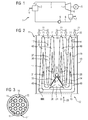
- the FIG. 1 shows a power plant 1.
- the power plant 1 comprises a steam generator 2, in which water is converted into steam by adding thermal energy.
- a line 3 is fluidically connected to the steam generator 2.
- the line 3 is connected to the input of a steam turbine 4.
- the thermal energy of the steam is converted in the steam turbine 4 into rotational energy of the rotor.
- the rotational energy of the rotor is used to generate electrical energy in a generator 5.
- the steam turbine 4 comprises a flow outlet 6, which is fluidically connected to a condenser 7. In the condenser 7, the steam is converted into water by condensation and is then passed through another line 8 and a pump 9 back to the steam generator 2, in which the addition of thermal energy 10, the water is converted back into steam.
- FIG. 2 shows an inventive arrangement 11, which has a capacitor 12 which has a capacitor housing 13 and disposed within the capacitor housing 13 tube bundle 14.
- the tube bundles are formed perpendicular to the leaf level and are traversed with water.
- FIG. 3 shows an enlarged view of the assembly 11 from FIG. 2 ,
- FIG. 3 is a part of the tube bundle 14 can be seen and shows an enlarged view of the detail III FIG. 2 ,
- the tube bundle 14 comprises a plurality of individual tubes 15 and for good order, only three tubes are provided with the reference numeral 15. During operation, cold water flows through these tubes 15, which causes the outer surface 16 of the tube 15 is cold and a vapor condenses on the cold outer surface 16 and drips down.
- the cross-sectional view of the tube bundles 14 shows according to FIG. 2 in that it is arrow-shaped in a flow direction 17.
- the condenser 12 comprises a condenser bottom 18. Parallel to the condenser bottom 18, the tube bundles are arranged substantially parallel to the condenser bottom 18. Towards the direction of flow, the tube bundles 14 are formed such that a first arrow surface 19 and a second arrow surface 20 are arranged so that they are formed obliquely and indeed at an angle ⁇ to the flow direction 17.
- Such a shaped tube bundle has a Rlickbündelspitze 21, which is flowed by a steam 22.
- FIG. 2 shows a total of four arrow-like approaching tube bundle 14. These Rrockbündel are such that they are formed in cross section as a V. Thus, seen in cross section, four upside-down pointed V's are formed. Approximately in the middle of the tube bundle, a further bundle of bundles of tubes 24 is formed, which points at an angle ⁇ arrow-like to the flow direction 17 out. At the top 25 of this bundle of tubes an air supply line with a tip 26 is arranged. The air supply line is designed such that air initially flows from top to bottom through the bundle bundle bundle 24 and exits downwards in accordance with the flow direction 26 and 27 and flows to the arrow-like tube bundles 14 along the flow directions 28, 29, 30 and 31.
- the arrangement further comprises an air suction device, which in the FIG. 2 not shown in detail.
- FIG. 4 shows the arrangement 1 in an enlarged view.
- the arrangement has a capacitor housing 13.
- the tube bundles 14 are according to FIG. 4 also arrow-like arranged in the flow direction 17.
- FIG. 4 8 arrow-like sub-bundles 14 are formed.
- the arrangement comprises an air suction device 38, which is designed for the extraction of air from the condenser.
- This air suction device 38 has a pump device 39 and is fluidically connected to a line 40.
- the line 40 is connected to a manifold 41.
- the collecting line 41 leads to a tip 25 between the tube bundles 14. Between the tip 25 and the pumping device 39, the air suction device 38 is designed such that air is sucked out of the condenser via the tip 25 in an air suction 42.
- the pumping device 39 has a pump 34 which is driven by a motor 44.
- the arrangement 1 has a 3-way valve 45, which has essentially two functions. In its first function, the 3-way valve 45 opens the conduit 40, so that in the Beerabsaugcardi 42 air from the condenser over the tip 25 to the Heilabsaugcardi 38 is performed.
- the 3-way valve 45 is designed such that via an air supply line 46 air through the 3-way valve 45 flows in the direction of a Beereinsaugcardi 47 toward the condenser. This air finally flows as in FIG. 2 seen over the top 25 down between the tube bundles 14.
- the arrow-like tube bundles 14 can also be designed as a partial tube bundle 48 with a base 49 and a tip 50.
Landscapes
- Engineering & Computer Science (AREA)
- Mechanical Engineering (AREA)
- General Engineering & Computer Science (AREA)
- Chemical & Material Sciences (AREA)
- Combustion & Propulsion (AREA)
- Engine Equipment That Uses Special Cycles (AREA)
Priority Applications (1)
| Application Number | Priority Date | Filing Date | Title |
|---|---|---|---|
| EP15186714.0A EP3147467A1 (fr) | 2015-09-24 | 2015-09-24 | Centrale electrique dotee de frein a vide |
Applications Claiming Priority (1)
| Application Number | Priority Date | Filing Date | Title |
|---|---|---|---|
| EP15186714.0A EP3147467A1 (fr) | 2015-09-24 | 2015-09-24 | Centrale electrique dotee de frein a vide |
Publications (1)
| Publication Number | Publication Date |
|---|---|
| EP3147467A1 true EP3147467A1 (fr) | 2017-03-29 |
Family
ID=54238259
Family Applications (1)
| Application Number | Title | Priority Date | Filing Date |
|---|---|---|---|
| EP15186714.0A Withdrawn EP3147467A1 (fr) | 2015-09-24 | 2015-09-24 | Centrale electrique dotee de frein a vide |
Country Status (1)
| Country | Link |
|---|---|
| EP (1) | EP3147467A1 (fr) |
Citations (7)
| Publication number | Priority date | Publication date | Assignee | Title |
|---|---|---|---|---|
| GB2147050A (en) * | 1983-09-27 | 1985-05-01 | Hick Hargreaves & Co Ltd | Liquid ring pumps |
| JPS61201802A (ja) * | 1985-03-04 | 1986-09-06 | Hitachi Ltd | タ−ビン強制冷却法及びその装置 |
| JPH08218811A (ja) * | 1995-02-16 | 1996-08-27 | Hitachi Ltd | 蒸気タービンの冷却方法及びその装置 |
| JP2006312882A (ja) * | 2005-05-06 | 2006-11-16 | Hitachi Ltd | 蒸気タービン発電プラント及びその運転方法 |
| JP2006349314A (ja) * | 2005-06-20 | 2006-12-28 | Toshiba Corp | 復水器の真空度制御装置およびその方法、並びに蒸気タービンプラント |
| US20140331671A1 (en) * | 2012-02-10 | 2014-11-13 | Alstom Technology Ltd | Water/steam cycle and method for operating the same |
| US20150000279A1 (en) * | 2012-03-19 | 2015-01-01 | Alstom Technology Ltd | Method for operating a power plant |
-
2015
- 2015-09-24 EP EP15186714.0A patent/EP3147467A1/fr not_active Withdrawn
Patent Citations (7)
| Publication number | Priority date | Publication date | Assignee | Title |
|---|---|---|---|---|
| GB2147050A (en) * | 1983-09-27 | 1985-05-01 | Hick Hargreaves & Co Ltd | Liquid ring pumps |
| JPS61201802A (ja) * | 1985-03-04 | 1986-09-06 | Hitachi Ltd | タ−ビン強制冷却法及びその装置 |
| JPH08218811A (ja) * | 1995-02-16 | 1996-08-27 | Hitachi Ltd | 蒸気タービンの冷却方法及びその装置 |
| JP2006312882A (ja) * | 2005-05-06 | 2006-11-16 | Hitachi Ltd | 蒸気タービン発電プラント及びその運転方法 |
| JP2006349314A (ja) * | 2005-06-20 | 2006-12-28 | Toshiba Corp | 復水器の真空度制御装置およびその方法、並びに蒸気タービンプラント |
| US20140331671A1 (en) * | 2012-02-10 | 2014-11-13 | Alstom Technology Ltd | Water/steam cycle and method for operating the same |
| US20150000279A1 (en) * | 2012-03-19 | 2015-01-01 | Alstom Technology Ltd | Method for operating a power plant |
Similar Documents
| Publication | Publication Date | Title |
|---|---|---|
| EP2136052B1 (fr) | Turbine à turbopropulseur dotée d'un dispositif de production d'un flux d'air de refroidissement | |
| EP2000649B1 (fr) | Moteur à réaction doté d'une circulation d'air de compresseur et procédé de fonctionnement de celui-ci | |
| EP1525396B2 (fr) | Turbine eolienne a circuit de refroidissement ferme | |
| EP2600015B1 (fr) | Turbocompresseur, système de piles à combustible | |
| CH698465A2 (de) | Vorrichtung und Verfahren zur Turbinenkühlung. | |
| DE102011052235A1 (de) | Druckbetätigter Stopfen | |
| DE102018112451A1 (de) | Vorrichtung zur Luftversorgung einer Brennstoffzelle, vorzugsweise einer mit Wasserstoff betriebenen, Brennstoffzelle | |
| EP2951066B1 (fr) | Circuit de refroidissement d'un véhicule automobile, muni d'un retardateur hydrodynamique | |
| DE102019209958A1 (de) | Brennstoffzellensystem und Verfahren | |
| CH715032B1 (de) | Vorrichtung zur Luftversorgung einer Brennstoffzelle. | |
| EP3665736B1 (fr) | Système de pile à combustible avec extraction en pression intermediaire d'un compresseur et utilisation dudit système | |
| EP2093386A2 (fr) | Système de lubrification des paliers d'une turbine à gaz avec récupération d'huile | |
| DE602004001156T2 (de) | Verdichtereinheit mit unterstützter Kühlung | |
| DE102012015325A1 (de) | Venturidüse zur Erzeugung eines Unterdrucks | |
| DE102008051980A1 (de) | Luftversorgungsvorrichtung für eine Brennstoffzelle | |
| EP3643396A1 (fr) | Dispositif de mélange de fluides fonctionnant en continu et respirant du fluide et son procédé de fonctionnement | |
| DE102018107104A1 (de) | Windenergieanlage | |
| EP3147467A1 (fr) | Centrale electrique dotee de frein a vide | |
| DE102004026633A1 (de) | Gasgekühlte elektrische Maschine mit Druckaufladung | |
| WO2024041783A1 (fr) | Système de pile à combustible et procédé de fonctionnement d'un système de pile à combustible | |
| DE102022133649A1 (de) | Brennstoffzellensystem und Verfahren zum Betrieb eines Brennstoffzellensystems | |
| DE102016214076A1 (de) | Ladeluftkühler | |
| DE102024131806A1 (de) | Kreiselpumpe mit einem Laufrad | |
| EP3109420A1 (fr) | Procédé de refroidissement d'une turbomachine | |
| EP1769137B1 (fr) | Turbine à vapeur comprenant un palier et dispositif d'étanchéité |
Legal Events
| Date | Code | Title | Description |
|---|---|---|---|
| PUAI | Public reference made under article 153(3) epc to a published international application that has entered the european phase |
Free format text: ORIGINAL CODE: 0009012 |
|
| AK | Designated contracting states |
Kind code of ref document: A1 Designated state(s): AL AT BE BG CH CY CZ DE DK EE ES FI FR GB GR HR HU IE IS IT LI LT LU LV MC MK MT NL NO PL PT RO RS SE SI SK SM TR |
|
| AX | Request for extension of the european patent |
Extension state: BA ME |
|
| RAP1 | Party data changed (applicant data changed or rights of an application transferred) |
Owner name: SIEMENS AKTIENGESELLSCHAFT |
|
| STAA | Information on the status of an ep patent application or granted ep patent |
Free format text: STATUS: THE APPLICATION IS DEEMED TO BE WITHDRAWN |
|
| 18D | Application deemed to be withdrawn |
Effective date: 20170930 |