EP3147493B1 - Dispositif d'injection de combustible - Google Patents
Dispositif d'injection de combustible Download PDFInfo
- Publication number
- EP3147493B1 EP3147493B1 EP16180972.8A EP16180972A EP3147493B1 EP 3147493 B1 EP3147493 B1 EP 3147493B1 EP 16180972 A EP16180972 A EP 16180972A EP 3147493 B1 EP3147493 B1 EP 3147493B1
- Authority
- EP
- European Patent Office
- Prior art keywords
- combustion chamber
- groove
- sealing ring
- fuel injection
- valve housing
- Prior art date
- Legal status (The legal status is an assumption and is not a legal conclusion. Google has not performed a legal analysis and makes no representation as to the accuracy of the status listed.)
- Active
Links
Images



Classifications
-
- F—MECHANICAL ENGINEERING; LIGHTING; HEATING; WEAPONS; BLASTING
- F02—COMBUSTION ENGINES; HOT-GAS OR COMBUSTION-PRODUCT ENGINE PLANTS
- F02M—SUPPLYING COMBUSTION ENGINES IN GENERAL WITH COMBUSTIBLE MIXTURES OR CONSTITUENTS THEREOF
- F02M61/00—Fuel-injectors not provided for in groups F02M39/00 - F02M57/00 or F02M67/00
- F02M61/14—Arrangements of injectors with respect to engines; Mounting of injectors
-
- F—MECHANICAL ENGINEERING; LIGHTING; HEATING; WEAPONS; BLASTING
- F02—COMBUSTION ENGINES; HOT-GAS OR COMBUSTION-PRODUCT ENGINE PLANTS
- F02F—CYLINDERS, PISTONS OR CASINGS, FOR COMBUSTION ENGINES; ARRANGEMENTS OF SEALINGS IN COMBUSTION ENGINES
- F02F1/00—Cylinders; Cylinder heads
- F02F1/24—Cylinder heads
- F02F1/242—Arrangement of spark plugs or injectors
-
- F—MECHANICAL ENGINEERING; LIGHTING; HEATING; WEAPONS; BLASTING
- F02—COMBUSTION ENGINES; HOT-GAS OR COMBUSTION-PRODUCT ENGINE PLANTS
- F02F—CYLINDERS, PISTONS OR CASINGS, FOR COMBUSTION ENGINES; ARRANGEMENTS OF SEALINGS IN COMBUSTION ENGINES
- F02F11/00—Arrangements of sealings in combustion engines
- F02F11/002—Arrangements of sealings in combustion engines involving cylinder heads
-
- F—MECHANICAL ENGINEERING; LIGHTING; HEATING; WEAPONS; BLASTING
- F02—COMBUSTION ENGINES; HOT-GAS OR COMBUSTION-PRODUCT ENGINE PLANTS
- F02M—SUPPLYING COMBUSTION ENGINES IN GENERAL WITH COMBUSTIBLE MIXTURES OR CONSTITUENTS THEREOF
- F02M2200/00—Details of fuel-injection apparatus, not otherwise provided for
- F02M2200/09—Fuel-injection apparatus having means for reducing noise
-
- F—MECHANICAL ENGINEERING; LIGHTING; HEATING; WEAPONS; BLASTING
- F02—COMBUSTION ENGINES; HOT-GAS OR COMBUSTION-PRODUCT ENGINE PLANTS
- F02M—SUPPLYING COMBUSTION ENGINES IN GENERAL WITH COMBUSTIBLE MIXTURES OR CONSTITUENTS THEREOF
- F02M2200/00—Details of fuel-injection apparatus, not otherwise provided for
- F02M2200/85—Mounting of fuel injection apparatus
- F02M2200/858—Mounting of fuel injection apparatus sealing arrangements between injector and engine
Definitions
- the invention is based on a fuel injection device according to the preamble of the main claim.
- a fuel injection device known from the prior art is shown by way of example, in which a fuel injection valve installed therein is provided in a receiving bore of a cylinder head of an internal combustion engine.
- intermediate elements are placed as support elements in the form of washers or the like on a shoulder of the receiving bore of the cylinder head. With the help of such intermediate elements, manufacturing and assembly tolerances are compensated and a bearing free of transverse forces is ensured even if the fuel injector is slightly inclined.
- the fuel injection device is particularly suitable for use in fuel injection systems of mixture-compressing externally ignited internal combustion engines.
- Different types of decoupling and / or damping elements can also be used at this installation point.
- the valve housing is designed with one and the same outer diameter, facing the combustion chamber and facing away from the groove for a sealing ring serving to seal the fuel injector against the combustion chamber gases.
- US2015034742 A1 , US2015053182 A1 and EP1357284 A1 disclose fuel injectors for fuel injection systems.
- the fuel injection device with the characterizing features of claim 1 has the advantage that it allows low-noise and bending stress-reduced tilting of a fuel injection valve with the greatest possible tolerance independence.
- the fuel injector comprises at least one fuel injector and a receiving bore in a cylinder head for the fuel injector, a sealing ring being provided in a groove of a valve housing on the outer circumference of the fuel injector, which is used to seal the fuel injector from the receiving bore.
- the valve housing advantageously has a smaller outer diameter, directly facing away from the combustion chamber, from the groove for the sealing ring than the outer diameter directly facing the combustion chamber from the groove for the sealing ring.
- the outer diameter for the valve housing, directly facing away from the combustion chamber is chosen precisely so that, taking into account the most extreme tolerance design of the valve housing outer diameter and the inner diameter of the receiving hole, no metallic contact of the fuel injector is facing away from the combustion chamber of the groove for the sealing ring on the wall of the receiving hole at the maximum possible The fuel injector is tilted.
- a sealing ring calibrated in the groove towards the front of the combustion chamber offers the advantage of avoiding the penetration of combustion chamber gases into the groove area as best as possible, since in this way no harmful dead spaces are formed in the groove area, so that in addition to the critical destructive effects, there are also undesirable pumping or suction effects are avoided.
- calibrating the sealing ring towards the front groove flank it is possible to completely dispense with an upper groove flank facing away from the combustion chamber and to continue the groove base diameter directly as the outer diameter of the valve housing facing away from the combustion chamber.
- FIG. 1 a known embodiment of a fuel injector described in more detail.
- the fuel injector 1 is part of the fuel injector.
- the downstream end of the fuel injector 1, which is designed in the form of a direct injection valve for injecting fuel directly into a combustion chamber 17 of the internal combustion engine, is installed in a receiving bore 20 of a cylinder head 9.
- a sealing ring 2, in particular made of Teflon TM, ensures optimal sealing of the fuel injector 1 with respect to the wall of the receiving bore 20 of the cylinder head 9.
- a flat intermediate element 24 which is designed as a support element in the form of a washer, is inserted between a shoulder 21 of a valve housing 22 and a shoulder 23 of the receiving bore 20 that extends, for example, at right angles to the longitudinal extension of the receiving bore 20.
- fuel injector 1 At its inlet end 3, fuel injector 1 has a plug-in connection to a fuel rail 4, which is sealed by a sealing ring 5 between a connector 6 of fuel distributor line 4, which is shown in section, and an inlet connector 7 of fuel injector 1.
- the fuel injector 1 is pushed into a receiving opening 12 of the connecting piece 6 of the fuel distributor line 4.
- the connecting piece 6 emerges in one piece from the actual fuel distributor line 4 and, upstream of the receiving opening 12, has a smaller-diameter flow opening 15 through which the fuel injector 1 flows.
- the fuel injector 1 has an electrical connector 8 for making electrical contact for actuating the fuel injector 1.
- a hold-down device 10 is provided between fuel injector 1 and connecting piece 6 in order to space fuel injector 1 and fuel distributor line 4 largely free of radial forces and to hold fuel injector 1 down securely in receiving bore 20 of cylinder head 9.
- the hold-down device 10 is designed as a bow-shaped component, for example as a stamped and bent part.
- the hold-down 10 has a partially annular base element 11, from which a hold-down bracket 13 extends, bent off, which is attached to a downstream end face 14 of the Connection piece 6 rests on the fuel distributor line 4 in the installed state.
- the object of the invention is to achieve improved tilting options for the fuel injector 1 in a simple manner compared to the known built-in solutions of fuel injectors intended for direct injection in receiving bores of cylinder heads, in order to be able to produce the individual components in a simplified manner that is less sensitive to tolerances and greater deviations from the alignment of the Axes of the connecting piece 6 of the fuel distributor line 4, the fuel injector 1 and the receiving bore 20 of the cylinder head 9 to be able to compensate.
- valve housing 22 of the fuel injector 1 is usually designed with one and the same outside diameter facing the combustion chamber and facing away from the combustion chamber of the groove for the sealing ring 2 serving to seal the fuel injector 1 against the combustion chamber gases.
- the very narrow gap between fuel injector 1 and receiving bore 20 facing the combustion chamber of sealing ring 2 is also facing away from the combustion chamber to avoid the ingress of harmful combustion chamber gases, i.e. above sealing ring 2 in its narrow gap width. Tilting of the fuel injector 1 without the valve housing 22 touching the wall of the receiving bore 20 on both sides in the area of the sealing ring 2 is thereby severely restricted.
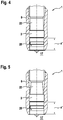
- the fuel injection device according to the invention is characterized in that the valve housing 22 has a smaller outer diameter immediately facing away from the combustion chamber from the groove for the sealing ring 2 than the outer diameter directly facing the combustion chamber from the groove for the sealing ring 2, as in the embodiment not covered by the claimed invention the Figure 2 is shown.
- a fuel injector 1 is provided in a receiving bore 20 of a cylinder head 9 which, according to the invention, has a valve housing 22 which, due to its optimized external geometry, allows greater tilting of the fuel injector 1 in the cylinder head 9 without this Valve housing 22 makes metallic contact with the receiving bore 20 of the cylinder head 9 on both sides.
- the best installation position of the sealing ring 2 will be discussed later.
- the receiving bore 20 usually runs in the area of the groove for the sealing ring 2 and the valve housing 22 both directly facing away from the combustion chamber and facing the groove on the fuel injector 1 in a cylindrical manner with a constant inner diameter.
- the receiving bore 20 then extends further away from the combustion chamber, for example, in a conical manner in order to be able to optimally introduce the fuel injector 1, as is the case with the Figures 1 to 6 clarify.
- the radial distance between the valve housing 22 and the receiving bore 20 directly facing away from the combustion chamber of the groove for the sealing ring 2 is greater than the radial distance between the valve housing 22 and the Receiving bore 20 facing the groove for the sealing ring 2 directly towards the combustion chamber.
- the radial distance between the valve housing 22 and the receiving bore 20 directly facing away from the combustion chamber of the groove for the sealing ring 2 is ideally greater than the radial distance between the valve housing 22 and the receiving bore 20 facing the combustion chamber Groove for the sealing ring 2 over the entire length up to an edge at which the combustion chamber 17 begins.
- valve housing 22 is shown in multiple steps facing the sealing ring 2, facing the combustion chamber.
- valve housing 22 of the fuel injector 1 facing the groove for the sealing ring 2 in the outer diameter can be constant or single or multiple stepped over the entire length up to an edge at which the combustion chamber 17 begins and the outer diameter of the valve housing 22
- the groove for the sealing ring 2 directly facing away from the combustion chamber is smaller than any outer diameter of the valve housing 22 facing the groove for the sealing ring 2 up to the edge at which the combustion chamber 17 begins.
- the gap width between the valve housing 22 of the fuel injector 1 and the wall of the receiving bore 20 facing the combustion chamber of the sealing ring 2 is typically only 50 to 100 ⁇ m in order to prevent combustion chamber gases from penetrating further into the receiving bore 20.
- a typical dimension for a fuel injector 1 for direct injection of fuel into a combustion chamber 17 is 7.5 mm for the outside diameter in the area of the end on the injection side. For example, a tolerance of +/- 50 ⁇ m must be observed.
- the inside diameter would accordingly be a typical value of 7.65 mm with a tolerance of +/- 25 ⁇ m.
- the outer diameter of the valve housing 22 is made 1 to 10% smaller than the outer diameter directly facing the combustion chamber directly facing away from the combustion chamber of the groove for the sealing ring 2 the groove for the sealing ring 2.
- a specific example provides that the outer diameter of the valve housing 22 facing away from the combustion chamber is 7.3 mm in relation to the above example. In terms of tolerance, metallic contact of fuel injector 1 away from the combustion chamber of the groove for sealing ring 2 on the wall of receiving bore 20 should therefore still be avoided with the smallest receiving bore 20 and the largest valve housing 22.
- the outer diameter for the valve housing 22, directly facing away from the combustion chamber is chosen precisely so that, taking into account the most extreme tolerance design of the valve housing outer diameter and the inner diameter of the receiving bore 20, there is no metallic contact of the fuel injector 1 away from the combustion chamber of the groove for the sealing ring 2 on the wall the receiving bore 20 is present at the maximum possible tilting of the fuel injector 1.
- the outer diameter of the valve housing 22 directly facing away from the combustion chamber of the groove for the sealing ring 2 should be 1 to 10% smaller than each of the outer diameter of the valve housing 22 facing the combustion chamber of the groove for the sealing ring 2 over the entire length up to an edge at which the Combustion chamber 17 begins.
- the 10% reduction in the outer diameter In any case, it is theoretically conceivable.
- the fuel injection device is designed according to the invention in such a way that the valve housing 22, immediately facing away from the groove for the sealing ring 2, has a conically tapering outer geometry, like this, away from the groove Figure 5 with a second embodiment in a detailed view of the end on the combustion chamber side of fuel injector 1 shows.
- the conicity of the valve housing 22 is not shown true to scale, since the angle of the external geometrical slope can in reality be ⁇ 1 ° and this would not be recognizable.
- Figure 6 shows a fuel injection device not covered by the claimed invention in a third embodiment in a detailed view of the end of the fuel injection valve 1 on the combustion chamber side 22 directly facing away from the combustion chamber, so that there is no upper groove flank at all and the outer geometry of the valve housing 22 can be produced particularly easily.
- a maximum tilting of the fuel injector 1 without metallic contact facing away from the combustion chamber of the groove for the sealing ring 2 is possible without restriction.
- sealing ring 2 when the fuel injector 1 is installed, does not sit in the middle of the groove, as shown, but rather sits on the lower groove flank of the groove facing the combustion chamber.
- a sealing ring 2 calibrated all the way to the front towards the combustion chamber 17 in the groove offers the advantage of the best possible avoidance of the penetration of combustion chamber gases into the groove area, since in this way no harmful dead spaces are formed in the groove area, so that in addition to the destructive effects, undesirable pumping or Sucking effects are avoided.
- publication DE 10 2009 045 692 A1 referring to the calibration of the sealing ring 2.
Landscapes
- Engineering & Computer Science (AREA)
- Chemical & Material Sciences (AREA)
- Combustion & Propulsion (AREA)
- Mechanical Engineering (AREA)
- General Engineering & Computer Science (AREA)
- Fuel-Injection Apparatus (AREA)
Claims (8)
- Dispositif d'injection de carburant destiné à des systèmes d'injection de carburant de moteurs à combustion interne, en particulier pour l'injection directe de carburant dans une chambre de combustion (17), le dispositif d'injection de carburant comprenant au moins une soupape d'injection de carburant (1) et un alésage de réception (20) qui est ménagé de préférence dans une tête de cylindre (9) et est destiné à la soupape d'injection de carburant (1), une bague d'étanchéité (2) étant prévue dans une rainure d'un boîtier de soupape (22) sur la circonférence extérieure de la soupape d'injection de carburant (1) et servant à assurer l'étanchéité de la soupape d'injecteur de carburant (1) par rapport à l'alésage de réception (20), le boîtier de soupape (22) ayant, du côté de la rainure destinée à la bague d'étanchéité (2) qui est directement opposé à la chambre de combustion, un diamètre extérieur inférieur au diamètre extérieur du côté de la rainure destinée à la bague d'étanchéité (2) qui est directement dirigé vers la chambre de combustion,caractérisé en ce quele boîtier de soupape (22) a, du côté de la rainure destinée à la bague d'étanchéité (2) qui est directement opposé à la chambre de combustion, une géométrie extérieure qui s'amincit en cône à mesure que l'on s'éloigne de la rainure.
- Dispositif d'injection de carburant selon la revendication 1,caractérisé en ce quel'alésage de réception (20) dans la zone de la rainure destinée à la bague d'étanchéité (2) et du boîtier de soupape (22) s'étend de manière cylindrique avec un diamètre intérieur constant, aussi bien du côté de la rainure qui est directement opposé à la chambre de combustion que du côté de la rainure qui est directement dirigé vers la chambre de combustion au niveau de la soupape d'injection de carburant (1).
- Dispositif d'injection de carburant selon la revendication 2,caractérisé en ce quela distance radiale entre le boîtier de soupape (22) et l'alésage de réception (20) du côté de la rainure destinée à la bague d'étanchéité (2) qui est directement opposé à la chambre de combustion est supérieure à la distance radiale entre le boîtier de soupape (22) et l'alésage de réception (20) du côté de la rainure destinée à la bague d'étanchéité (2) qui est directement dirigé vers la chambre de combustion.
- Dispositif d'injection de carburant selon la revendication 3,caractérisé en ce quela distance radiale entre le boîtier de soupape (22) et l'alésage de réception (20), du côté de la rainure destinée à la bague d'étanchéité (2) qui est directement opposé à la chambre de combustion, est supérieure à la distance radiale entre le boîtier de soupape (22) et le alésage de réception (20), du côté de la rainure destinée à la bague d'étanchéité (2) qui est dirigé directement vers la chambre de combustion, sur toute la longueur jusqu'à un bord où commence la chambre de combustion (17).
- Dispositif d'injection de carburant selon l'une des revendications précédentes,caractérisé en ce quele boîtier de soupape (22) de la soupape d'injection de carburant (1), du côté de la rainure destinée à la bague d'étanchéité (2) qui est dirigé vers la chambre de combustion, est réalisé de manière à avoir un diamètre extérieur constant ou étagé une ou plusieurs fois sur toute la longueur jusqu'à un bord où la chambre de combustion (17) commence, et le diamètre extérieur du boîtier de soupape (22), du côté de la rainure destinée à la bague d'étanchéité (2) qui est directement opposé à la chambre de combustion, est inférieur à tout diamètre extérieur du boîtier de soupape (22), du côté de la rainure destinée à la bague d'étanchéité (2) qui est dirigé vers la chambre de combustion, jusqu'au bord où la chambre de combustion (17) commence.
- Dispositif d'injection de carburant selon l'une des revendications précédentes,caractérisé en ce quele diamètre extérieur du boîtier de soupape (22), du côté de la rainure destinée à la bague d'étanchéité (2) qui est directement opposé à la chambre de combustion, est inférieur de 1 à 10 % au diamètre extérieur du côté de la rainure destinée à la bague d'étanchéité (2) qui est directement dirigé vers la chambre de combustion.
- Dispositif d'injection de carburant selon l'une des revendications précédentes,caractérisé en ce quele diamètre extérieur du boîtier de soupape (22), du côté de la rainure destinée à la bague d'étanchéité (2) qui est directement opposé à la chambre de combustion, est inférieur de 1 à 10 % à chacun des diamètres extérieurs du côté de la rainure destinée à la bague d'étanchéité (2) qui est dirigé vers la chambre de combustion, sur toute la longueur jusqu'à un bord où la chambre de combustion (17) commence.
- Dispositif d'injection de carburant selon l'une des revendications précédentes,caractérisé en ce quela bague d'étanchéité (2) siège sur le bord inférieur de la rainure, qui est dirigé vers la chambre de combustion, lorsque la soupape d'injection de carburant (1) est montée.
Applications Claiming Priority (1)
| Application Number | Priority Date | Filing Date | Title |
|---|---|---|---|
| DE102015218194.4A DE102015218194A1 (de) | 2015-09-22 | 2015-09-22 | Brennstoffeinspritzvorrichtung |
Publications (2)
| Publication Number | Publication Date |
|---|---|
| EP3147493A1 EP3147493A1 (fr) | 2017-03-29 |
| EP3147493B1 true EP3147493B1 (fr) | 2021-09-29 |
Family
ID=56511436
Family Applications (1)
| Application Number | Title | Priority Date | Filing Date |
|---|---|---|---|
| EP16180972.8A Active EP3147493B1 (fr) | 2015-09-22 | 2016-07-25 | Dispositif d'injection de combustible |
Country Status (3)
| Country | Link |
|---|---|
| EP (1) | EP3147493B1 (fr) |
| KR (1) | KR20170035335A (fr) |
| DE (1) | DE102015218194A1 (fr) |
Families Citing this family (1)
| Publication number | Priority date | Publication date | Assignee | Title |
|---|---|---|---|---|
| DE102018216970A1 (de) * | 2018-10-04 | 2020-04-09 | Robert Bosch Gmbh | Brennstoffeinspritzvorrichtung |
Family Cites Families (5)
| Publication number | Priority date | Publication date | Assignee | Title |
|---|---|---|---|---|
| US6938901B2 (en) * | 2000-12-26 | 2005-09-06 | Toyota Jidosha Kabushiki Kaisha | Combustion gas seal for injector and sealing structure with the combustion gas seal |
| US7406946B1 (en) * | 2007-04-02 | 2008-08-05 | Hitachi, Ltd. | Method and apparatus for attenuating fuel pump noise in a direct injection internal combustion chamber |
| DE102009045692A1 (de) | 2009-10-14 | 2011-04-21 | Robert Bosch Gmbh | Verfahren zur Montage eines Dichtungsrings |
| JP2015028322A (ja) * | 2013-07-30 | 2015-02-12 | 株式会社デンソー | 燃料噴射弁 |
| JP5910586B2 (ja) * | 2013-08-23 | 2016-04-27 | 株式会社デンソー | 燃料噴射弁 |
-
2015
- 2015-09-22 DE DE102015218194.4A patent/DE102015218194A1/de not_active Ceased
-
2016
- 2016-07-25 EP EP16180972.8A patent/EP3147493B1/fr active Active
- 2016-09-21 KR KR1020160120540A patent/KR20170035335A/ko not_active Withdrawn
Also Published As
| Publication number | Publication date |
|---|---|
| DE102015218194A1 (de) | 2017-03-23 |
| KR20170035335A (ko) | 2017-03-30 |
| EP3147493A1 (fr) | 2017-03-29 |
Similar Documents
| Publication | Publication Date | Title |
|---|---|---|
| EP2961977B1 (fr) | Dispositif pour l'injection de carburant dans une chambre de combustion d'un moteur à combustion | |
| EP1290338B1 (fr) | Moteur a combustion interne | |
| EP3234346B1 (fr) | Dispositif d'injection de carburant | |
| EP1332285B1 (fr) | Installation d'injection de carburant | |
| WO2020150758A1 (fr) | Moteur a combustion interne refroidi par liquide | |
| WO2003018997A1 (fr) | Element de compensation conçu pour une soupape d'injection de carburant | |
| EP3147493B1 (fr) | Dispositif d'injection de combustible | |
| EP2252786B1 (fr) | Traversée électrique étanchéifiée | |
| EP4158233B1 (fr) | Fiche de connexion et ensemble fiche formé à partir de celle-ci | |
| DE10109411A1 (de) | Brennstoffeinspritzventil | |
| EP3662156B1 (fr) | Soupape d'injection de carburant | |
| DE102007053800A1 (de) | Kraftstoffsystem einer Brennkraftmaschine | |
| DE102020202949A1 (de) | Brennstoffeinspritzvorrichtung | |
| DE10158337C1 (de) | Kraftstoff-Einspritzvorrichtung, insbesondere Injektor für Brennkraftmaschinen mit Direkteinspritzung, sowie Kraftstoffsystem und Brennkraftmaschine | |
| EP3168454B1 (fr) | Vanne de dosage de fluide et dispositif comprenant une telle vanne | |
| DE102016210573B4 (de) | Anordnung zur Verbindung mindestens eines Brennstoffeinspritzventils an einem Kraftstoffverteiler einer Kraftstoffeinspritzanlage und Kraftstoffeinspritzanlage einer Brennkraftmaschine | |
| DE102006042457B4 (de) | Ausgerichtete Zündkerze | |
| EP1780403B1 (fr) | Soupape d'injection de combustible | |
| WO2021083701A1 (fr) | Soupape d'injection de carburant | |
| DE10200044A1 (de) | Brennstoffeinspritzventil | |
| EP3314114B1 (fr) | Injecteur de carburant | |
| DE102021212779A1 (de) | Brennstoffeinspritzventil | |
| WO2024083411A1 (fr) | Agencement d'injecteur de carburant pour installer un injecteur de carburant dans un moteur à combustion interne | |
| DE102020213354A1 (de) | Brennstoffeinspritzventil | |
| DE102021214077A1 (de) | Brennstoffeinspritzventil |
Legal Events
| Date | Code | Title | Description |
|---|---|---|---|
| PUAI | Public reference made under article 153(3) epc to a published international application that has entered the european phase |
Free format text: ORIGINAL CODE: 0009012 |
|
| STAA | Information on the status of an ep patent application or granted ep patent |
Free format text: STATUS: THE APPLICATION HAS BEEN PUBLISHED |
|
| AK | Designated contracting states |
Kind code of ref document: A1 Designated state(s): AL AT BE BG CH CY CZ DE DK EE ES FI FR GB GR HR HU IE IS IT LI LT LU LV MC MK MT NL NO PL PT RO RS SE SI SK SM TR |
|
| AX | Request for extension of the european patent |
Extension state: BA ME |
|
| STAA | Information on the status of an ep patent application or granted ep patent |
Free format text: STATUS: REQUEST FOR EXAMINATION WAS MADE |
|
| 17P | Request for examination filed |
Effective date: 20170929 |
|
| RBV | Designated contracting states (corrected) |
Designated state(s): AL AT BE BG CH CY CZ DE DK EE ES FI FR GB GR HR HU IE IS IT LI LT LU LV MC MK MT NL NO PL PT RO RS SE SI SK SM TR |
|
| STAA | Information on the status of an ep patent application or granted ep patent |
Free format text: STATUS: EXAMINATION IS IN PROGRESS |
|
| 17Q | First examination report despatched |
Effective date: 20190117 |
|
| RAP1 | Party data changed (applicant data changed or rights of an application transferred) |
Owner name: ROBERT BOSCH GMBH |
|
| GRAP | Despatch of communication of intention to grant a patent |
Free format text: ORIGINAL CODE: EPIDOSNIGR1 |
|
| STAA | Information on the status of an ep patent application or granted ep patent |
Free format text: STATUS: GRANT OF PATENT IS INTENDED |
|
| INTG | Intention to grant announced |
Effective date: 20210609 |
|
| GRAS | Grant fee paid |
Free format text: ORIGINAL CODE: EPIDOSNIGR3 |
|
| GRAA | (expected) grant |
Free format text: ORIGINAL CODE: 0009210 |
|
| STAA | Information on the status of an ep patent application or granted ep patent |
Free format text: STATUS: THE PATENT HAS BEEN GRANTED |
|
| AK | Designated contracting states |
Kind code of ref document: B1 Designated state(s): AL AT BE BG CH CY CZ DE DK EE ES FI FR GB GR HR HU IE IS IT LI LT LU LV MC MK MT NL NO PL PT RO RS SE SI SK SM TR |
|
| REG | Reference to a national code |
Ref country code: GB Ref legal event code: FG4D Free format text: NOT ENGLISH |
|
| REG | Reference to a national code |
Ref country code: DE Ref legal event code: R096 Ref document number: 502016013901 Country of ref document: DE |
|
| REG | Reference to a national code |
Ref country code: CH Ref legal event code: EP Ref country code: AT Ref legal event code: REF Ref document number: 1434405 Country of ref document: AT Kind code of ref document: T Effective date: 20211015 |
|
| REG | Reference to a national code |
Ref country code: IE Ref legal event code: FG4D Free format text: LANGUAGE OF EP DOCUMENT: GERMAN |
|
| REG | Reference to a national code |
Ref country code: LT Ref legal event code: MG9D |
|
| PG25 | Lapsed in a contracting state [announced via postgrant information from national office to epo] |
Ref country code: HR Free format text: LAPSE BECAUSE OF FAILURE TO SUBMIT A TRANSLATION OF THE DESCRIPTION OR TO PAY THE FEE WITHIN THE PRESCRIBED TIME-LIMIT Effective date: 20210929 Ref country code: SE Free format text: LAPSE BECAUSE OF FAILURE TO SUBMIT A TRANSLATION OF THE DESCRIPTION OR TO PAY THE FEE WITHIN THE PRESCRIBED TIME-LIMIT Effective date: 20210929 Ref country code: RS Free format text: LAPSE BECAUSE OF FAILURE TO SUBMIT A TRANSLATION OF THE DESCRIPTION OR TO PAY THE FEE WITHIN THE PRESCRIBED TIME-LIMIT Effective date: 20210929 Ref country code: LT Free format text: LAPSE BECAUSE OF FAILURE TO SUBMIT A TRANSLATION OF THE DESCRIPTION OR TO PAY THE FEE WITHIN THE PRESCRIBED TIME-LIMIT Effective date: 20210929 Ref country code: BG Free format text: LAPSE BECAUSE OF FAILURE TO SUBMIT A TRANSLATION OF THE DESCRIPTION OR TO PAY THE FEE WITHIN THE PRESCRIBED TIME-LIMIT Effective date: 20211229 Ref country code: NO Free format text: LAPSE BECAUSE OF FAILURE TO SUBMIT A TRANSLATION OF THE DESCRIPTION OR TO PAY THE FEE WITHIN THE PRESCRIBED TIME-LIMIT Effective date: 20211229 Ref country code: FI Free format text: LAPSE BECAUSE OF FAILURE TO SUBMIT A TRANSLATION OF THE DESCRIPTION OR TO PAY THE FEE WITHIN THE PRESCRIBED TIME-LIMIT Effective date: 20210929 |
|
| REG | Reference to a national code |
Ref country code: NL Ref legal event code: MP Effective date: 20210929 |
|
| PG25 | Lapsed in a contracting state [announced via postgrant information from national office to epo] |
Ref country code: LV Free format text: LAPSE BECAUSE OF FAILURE TO SUBMIT A TRANSLATION OF THE DESCRIPTION OR TO PAY THE FEE WITHIN THE PRESCRIBED TIME-LIMIT Effective date: 20210929 Ref country code: GR Free format text: LAPSE BECAUSE OF FAILURE TO SUBMIT A TRANSLATION OF THE DESCRIPTION OR TO PAY THE FEE WITHIN THE PRESCRIBED TIME-LIMIT Effective date: 20211230 |
|
| PG25 | Lapsed in a contracting state [announced via postgrant information from national office to epo] |
Ref country code: IS Free format text: LAPSE BECAUSE OF FAILURE TO SUBMIT A TRANSLATION OF THE DESCRIPTION OR TO PAY THE FEE WITHIN THE PRESCRIBED TIME-LIMIT Effective date: 20220129 Ref country code: SK Free format text: LAPSE BECAUSE OF FAILURE TO SUBMIT A TRANSLATION OF THE DESCRIPTION OR TO PAY THE FEE WITHIN THE PRESCRIBED TIME-LIMIT Effective date: 20210929 Ref country code: RO Free format text: LAPSE BECAUSE OF FAILURE TO SUBMIT A TRANSLATION OF THE DESCRIPTION OR TO PAY THE FEE WITHIN THE PRESCRIBED TIME-LIMIT Effective date: 20210929 Ref country code: PT Free format text: LAPSE BECAUSE OF FAILURE TO SUBMIT A TRANSLATION OF THE DESCRIPTION OR TO PAY THE FEE WITHIN THE PRESCRIBED TIME-LIMIT Effective date: 20220131 Ref country code: PL Free format text: LAPSE BECAUSE OF FAILURE TO SUBMIT A TRANSLATION OF THE DESCRIPTION OR TO PAY THE FEE WITHIN THE PRESCRIBED TIME-LIMIT Effective date: 20210929 Ref country code: NL Free format text: LAPSE BECAUSE OF FAILURE TO SUBMIT A TRANSLATION OF THE DESCRIPTION OR TO PAY THE FEE WITHIN THE PRESCRIBED TIME-LIMIT Effective date: 20210929 Ref country code: ES Free format text: LAPSE BECAUSE OF FAILURE TO SUBMIT A TRANSLATION OF THE DESCRIPTION OR TO PAY THE FEE WITHIN THE PRESCRIBED TIME-LIMIT Effective date: 20210929 Ref country code: EE Free format text: LAPSE BECAUSE OF FAILURE TO SUBMIT A TRANSLATION OF THE DESCRIPTION OR TO PAY THE FEE WITHIN THE PRESCRIBED TIME-LIMIT Effective date: 20210929 Ref country code: CZ Free format text: LAPSE BECAUSE OF FAILURE TO SUBMIT A TRANSLATION OF THE DESCRIPTION OR TO PAY THE FEE WITHIN THE PRESCRIBED TIME-LIMIT Effective date: 20210929 Ref country code: AL Free format text: LAPSE BECAUSE OF FAILURE TO SUBMIT A TRANSLATION OF THE DESCRIPTION OR TO PAY THE FEE WITHIN THE PRESCRIBED TIME-LIMIT Effective date: 20210929 |
|
| REG | Reference to a national code |
Ref country code: DE Ref legal event code: R097 Ref document number: 502016013901 Country of ref document: DE |
|
| PG25 | Lapsed in a contracting state [announced via postgrant information from national office to epo] |
Ref country code: DK Free format text: LAPSE BECAUSE OF FAILURE TO SUBMIT A TRANSLATION OF THE DESCRIPTION OR TO PAY THE FEE WITHIN THE PRESCRIBED TIME-LIMIT Effective date: 20210929 |
|
| PLBE | No opposition filed within time limit |
Free format text: ORIGINAL CODE: 0009261 |
|
| STAA | Information on the status of an ep patent application or granted ep patent |
Free format text: STATUS: NO OPPOSITION FILED WITHIN TIME LIMIT |
|
| 26N | No opposition filed |
Effective date: 20220630 |
|
| PGFP | Annual fee paid to national office [announced via postgrant information from national office to epo] |
Ref country code: IT Payment date: 20220729 Year of fee payment: 7 |
|
| PG25 | Lapsed in a contracting state [announced via postgrant information from national office to epo] |
Ref country code: SI Free format text: LAPSE BECAUSE OF FAILURE TO SUBMIT A TRANSLATION OF THE DESCRIPTION OR TO PAY THE FEE WITHIN THE PRESCRIBED TIME-LIMIT Effective date: 20210929 |
|
| PGFP | Annual fee paid to national office [announced via postgrant information from national office to epo] |
Ref country code: FR Payment date: 20220725 Year of fee payment: 7 |
|
| PG25 | Lapsed in a contracting state [announced via postgrant information from national office to epo] |
Ref country code: MC Free format text: LAPSE BECAUSE OF FAILURE TO SUBMIT A TRANSLATION OF THE DESCRIPTION OR TO PAY THE FEE WITHIN THE PRESCRIBED TIME-LIMIT Effective date: 20210929 |
|
| REG | Reference to a national code |
Ref country code: CH Ref legal event code: PL |
|
| GBPC | Gb: european patent ceased through non-payment of renewal fee |
Effective date: 20220725 |
|
| REG | Reference to a national code |
Ref country code: BE Ref legal event code: MM Effective date: 20220731 |
|
| PG25 | Lapsed in a contracting state [announced via postgrant information from national office to epo] |
Ref country code: LU Free format text: LAPSE BECAUSE OF NON-PAYMENT OF DUE FEES Effective date: 20220725 Ref country code: LI Free format text: LAPSE BECAUSE OF NON-PAYMENT OF DUE FEES Effective date: 20220731 Ref country code: CH Free format text: LAPSE BECAUSE OF NON-PAYMENT OF DUE FEES Effective date: 20220731 |
|
| PG25 | Lapsed in a contracting state [announced via postgrant information from national office to epo] |
Ref country code: GB Free format text: LAPSE BECAUSE OF NON-PAYMENT OF DUE FEES Effective date: 20220725 Ref country code: BE Free format text: LAPSE BECAUSE OF NON-PAYMENT OF DUE FEES Effective date: 20220731 |
|
| PG25 | Lapsed in a contracting state [announced via postgrant information from national office to epo] |
Ref country code: IE Free format text: LAPSE BECAUSE OF NON-PAYMENT OF DUE FEES Effective date: 20220725 |
|
| REG | Reference to a national code |
Ref country code: AT Ref legal event code: MM01 Ref document number: 1434405 Country of ref document: AT Kind code of ref document: T Effective date: 20220725 |
|
| PG25 | Lapsed in a contracting state [announced via postgrant information from national office to epo] |
Ref country code: AT Free format text: LAPSE BECAUSE OF NON-PAYMENT OF DUE FEES Effective date: 20220725 |
|
| PG25 | Lapsed in a contracting state [announced via postgrant information from national office to epo] |
Ref country code: HU Free format text: LAPSE BECAUSE OF FAILURE TO SUBMIT A TRANSLATION OF THE DESCRIPTION OR TO PAY THE FEE WITHIN THE PRESCRIBED TIME-LIMIT; INVALID AB INITIO Effective date: 20160725 |
|
| PG25 | Lapsed in a contracting state [announced via postgrant information from national office to epo] |
Ref country code: SM Free format text: LAPSE BECAUSE OF FAILURE TO SUBMIT A TRANSLATION OF THE DESCRIPTION OR TO PAY THE FEE WITHIN THE PRESCRIBED TIME-LIMIT Effective date: 20210929 Ref country code: MK Free format text: LAPSE BECAUSE OF FAILURE TO SUBMIT A TRANSLATION OF THE DESCRIPTION OR TO PAY THE FEE WITHIN THE PRESCRIBED TIME-LIMIT Effective date: 20210929 Ref country code: CY Free format text: LAPSE BECAUSE OF FAILURE TO SUBMIT A TRANSLATION OF THE DESCRIPTION OR TO PAY THE FEE WITHIN THE PRESCRIBED TIME-LIMIT Effective date: 20210929 |
|
| PG25 | Lapsed in a contracting state [announced via postgrant information from national office to epo] |
Ref country code: FR Free format text: LAPSE BECAUSE OF NON-PAYMENT OF DUE FEES Effective date: 20230731 |
|
| PG25 | Lapsed in a contracting state [announced via postgrant information from national office to epo] |
Ref country code: IT Free format text: LAPSE BECAUSE OF NON-PAYMENT OF DUE FEES Effective date: 20230725 |
|
| PG25 | Lapsed in a contracting state [announced via postgrant information from national office to epo] |
Ref country code: MT Free format text: LAPSE BECAUSE OF FAILURE TO SUBMIT A TRANSLATION OF THE DESCRIPTION OR TO PAY THE FEE WITHIN THE PRESCRIBED TIME-LIMIT Effective date: 20210929 |
|
| PGFP | Annual fee paid to national office [announced via postgrant information from national office to epo] |
Ref country code: DE Payment date: 20250924 Year of fee payment: 10 |
|
| PG25 | Lapsed in a contracting state [announced via postgrant information from national office to epo] |
Ref country code: TR Free format text: LAPSE BECAUSE OF FAILURE TO SUBMIT A TRANSLATION OF THE DESCRIPTION OR TO PAY THE FEE WITHIN THE PRESCRIBED TIME-LIMIT Effective date: 20210929 |