EP3147497A1 - Läufereinheit für eine wasserturbine - Google Patents
Läufereinheit für eine wasserturbine Download PDFInfo
- Publication number
- EP3147497A1 EP3147497A1 EP15290238.3A EP15290238A EP3147497A1 EP 3147497 A1 EP3147497 A1 EP 3147497A1 EP 15290238 A EP15290238 A EP 15290238A EP 3147497 A1 EP3147497 A1 EP 3147497A1
- Authority
- EP
- European Patent Office
- Prior art keywords
- runner
- end tip
- tip portion
- blade
- runner unit
- Prior art date
- Legal status (The legal status is an assumption and is not a legal conclusion. Google has not performed a legal analysis and makes no representation as to the accuracy of the status listed.)
- Withdrawn
Links
Images

Classifications
-
- F—MECHANICAL ENGINEERING; LIGHTING; HEATING; WEAPONS; BLASTING
- F03—MACHINES OR ENGINES FOR LIQUIDS; WIND, SPRING, OR WEIGHT MOTORS; PRODUCING MECHANICAL POWER OR A REACTIVE PROPULSIVE THRUST, NOT OTHERWISE PROVIDED FOR
- F03B—MACHINES OR ENGINES FOR LIQUIDS
- F03B3/00—Machines or engines of reaction type; Parts or details peculiar thereto
- F03B3/12—Blades; Blade-carrying rotors
-
- F—MECHANICAL ENGINEERING; LIGHTING; HEATING; WEAPONS; BLASTING
- F03—MACHINES OR ENGINES FOR LIQUIDS; WIND, SPRING, OR WEIGHT MOTORS; PRODUCING MECHANICAL POWER OR A REACTIVE PROPULSIVE THRUST, NOT OTHERWISE PROVIDED FOR
- F03B—MACHINES OR ENGINES FOR LIQUIDS
- F03B3/00—Machines or engines of reaction type; Parts or details peculiar thereto
- F03B3/04—Machines or engines of reaction type; Parts or details peculiar thereto with substantially axial flow throughout rotors, e.g. propeller turbines
- F03B3/06—Machines or engines of reaction type; Parts or details peculiar thereto with substantially axial flow throughout rotors, e.g. propeller turbines with adjustable blades, e.g. Kaplan turbines
-
- F—MECHANICAL ENGINEERING; LIGHTING; HEATING; WEAPONS; BLASTING
- F03—MACHINES OR ENGINES FOR LIQUIDS; WIND, SPRING, OR WEIGHT MOTORS; PRODUCING MECHANICAL POWER OR A REACTIVE PROPULSIVE THRUST, NOT OTHERWISE PROVIDED FOR
- F03B—MACHINES OR ENGINES FOR LIQUIDS
- F03B11/00—Parts or details not provided for in, or of interest apart from, the preceding groups, e.g. wear-protection couplings, between turbine and generator
- F03B11/006—Sealing arrangements
-
- F—MECHANICAL ENGINEERING; LIGHTING; HEATING; WEAPONS; BLASTING
- F03—MACHINES OR ENGINES FOR LIQUIDS; WIND, SPRING, OR WEIGHT MOTORS; PRODUCING MECHANICAL POWER OR A REACTIVE PROPULSIVE THRUST, NOT OTHERWISE PROVIDED FOR
- F03B—MACHINES OR ENGINES FOR LIQUIDS
- F03B13/00—Adaptations of machines or engines for special use; Combinations of machines or engines with driving or driven apparatus; Power stations or aggregates
- F03B13/12—Adaptations of machines or engines for special use; Combinations of machines or engines with driving or driven apparatus; Power stations or aggregates characterised by using wave or tide energy
- F03B13/26—Adaptations of machines or engines for special use; Combinations of machines or engines with driving or driven apparatus; Power stations or aggregates characterised by using wave or tide energy using tide energy
-
- F—MECHANICAL ENGINEERING; LIGHTING; HEATING; WEAPONS; BLASTING
- F03—MACHINES OR ENGINES FOR LIQUIDS; WIND, SPRING, OR WEIGHT MOTORS; PRODUCING MECHANICAL POWER OR A REACTIVE PROPULSIVE THRUST, NOT OTHERWISE PROVIDED FOR
- F03B—MACHINES OR ENGINES FOR LIQUIDS
- F03B3/00—Machines or engines of reaction type; Parts or details peculiar thereto
- F03B3/12—Blades; Blade-carrying rotors
- F03B3/14—Rotors having adjustable blades
-
- F—MECHANICAL ENGINEERING; LIGHTING; HEATING; WEAPONS; BLASTING
- F03—MACHINES OR ENGINES FOR LIQUIDS; WIND, SPRING, OR WEIGHT MOTORS; PRODUCING MECHANICAL POWER OR A REACTIVE PROPULSIVE THRUST, NOT OTHERWISE PROVIDED FOR
- F03B—MACHINES OR ENGINES FOR LIQUIDS
- F03B3/00—Machines or engines of reaction type; Parts or details peculiar thereto
- F03B3/12—Blades; Blade-carrying rotors
- F03B3/14—Rotors having adjustable blades
- F03B3/145—Mechanisms for adjusting the blades
-
- F—MECHANICAL ENGINEERING; LIGHTING; HEATING; WEAPONS; BLASTING
- F05—INDEXING SCHEMES RELATING TO ENGINES OR PUMPS IN VARIOUS SUBCLASSES OF CLASSES F01-F04
- F05B—INDEXING SCHEME RELATING TO WIND, SPRING, WEIGHT, INERTIA OR LIKE MOTORS, TO MACHINES OR ENGINES FOR LIQUIDS COVERED BY SUBCLASSES F03B, F03D AND F03G
- F05B2220/00—Application
- F05B2220/30—Application in turbines
- F05B2220/32—Application in turbines in water turbines
-
- F—MECHANICAL ENGINEERING; LIGHTING; HEATING; WEAPONS; BLASTING
- F05—INDEXING SCHEMES RELATING TO ENGINES OR PUMPS IN VARIOUS SUBCLASSES OF CLASSES F01-F04
- F05B—INDEXING SCHEME RELATING TO WIND, SPRING, WEIGHT, INERTIA OR LIKE MOTORS, TO MACHINES OR ENGINES FOR LIQUIDS COVERED BY SUBCLASSES F03B, F03D AND F03G
- F05B2240/00—Components
- F05B2240/20—Rotors
-
- F—MECHANICAL ENGINEERING; LIGHTING; HEATING; WEAPONS; BLASTING
- F05—INDEXING SCHEMES RELATING TO ENGINES OR PUMPS IN VARIOUS SUBCLASSES OF CLASSES F01-F04
- F05B—INDEXING SCHEME RELATING TO WIND, SPRING, WEIGHT, INERTIA OR LIKE MOTORS, TO MACHINES OR ENGINES FOR LIQUIDS COVERED BY SUBCLASSES F03B, F03D AND F03G
- F05B2240/00—Components
- F05B2240/57—Seals
-
- F—MECHANICAL ENGINEERING; LIGHTING; HEATING; WEAPONS; BLASTING
- F05—INDEXING SCHEMES RELATING TO ENGINES OR PUMPS IN VARIOUS SUBCLASSES OF CLASSES F01-F04
- F05B—INDEXING SCHEME RELATING TO WIND, SPRING, WEIGHT, INERTIA OR LIKE MOTORS, TO MACHINES OR ENGINES FOR LIQUIDS COVERED BY SUBCLASSES F03B, F03D AND F03G
- F05B2240/00—Components
- F05B2240/60—Shafts
-
- F—MECHANICAL ENGINEERING; LIGHTING; HEATING; WEAPONS; BLASTING
- F05—INDEXING SCHEMES RELATING TO ENGINES OR PUMPS IN VARIOUS SUBCLASSES OF CLASSES F01-F04
- F05B—INDEXING SCHEME RELATING TO WIND, SPRING, WEIGHT, INERTIA OR LIKE MOTORS, TO MACHINES OR ENGINES FOR LIQUIDS COVERED BY SUBCLASSES F03B, F03D AND F03G
- F05B2250/00—Geometry
- F05B2250/02—Geometry variable
-
- F—MECHANICAL ENGINEERING; LIGHTING; HEATING; WEAPONS; BLASTING
- F05—INDEXING SCHEMES RELATING TO ENGINES OR PUMPS IN VARIOUS SUBCLASSES OF CLASSES F01-F04
- F05B—INDEXING SCHEME RELATING TO WIND, SPRING, WEIGHT, INERTIA OR LIKE MOTORS, TO MACHINES OR ENGINES FOR LIQUIDS COVERED BY SUBCLASSES F03B, F03D AND F03G
- F05B2250/00—Geometry
- F05B2250/40—Movement of component
-
- F—MECHANICAL ENGINEERING; LIGHTING; HEATING; WEAPONS; BLASTING
- F05—INDEXING SCHEMES RELATING TO ENGINES OR PUMPS IN VARIOUS SUBCLASSES OF CLASSES F01-F04
- F05B—INDEXING SCHEME RELATING TO WIND, SPRING, WEIGHT, INERTIA OR LIKE MOTORS, TO MACHINES OR ENGINES FOR LIQUIDS COVERED BY SUBCLASSES F03B, F03D AND F03G
- F05B2260/00—Function
- F05B2260/50—Kinematic linkage, i.e. transmission of position
- F05B2260/506—Kinematic linkage, i.e. transmission of position using cams or eccentrics
-
- F—MECHANICAL ENGINEERING; LIGHTING; HEATING; WEAPONS; BLASTING
- F05—INDEXING SCHEMES RELATING TO ENGINES OR PUMPS IN VARIOUS SUBCLASSES OF CLASSES F01-F04
- F05B—INDEXING SCHEME RELATING TO WIND, SPRING, WEIGHT, INERTIA OR LIKE MOTORS, TO MACHINES OR ENGINES FOR LIQUIDS COVERED BY SUBCLASSES F03B, F03D AND F03G
- F05B2260/00—Function
- F05B2260/70—Adjusting of angle of incidence or attack of rotating blades
- F05B2260/76—Adjusting of angle of incidence or attack of rotating blades the adjusting mechanism using auxiliary power sources
-
- F—MECHANICAL ENGINEERING; LIGHTING; HEATING; WEAPONS; BLASTING
- F05—INDEXING SCHEMES RELATING TO ENGINES OR PUMPS IN VARIOUS SUBCLASSES OF CLASSES F01-F04
- F05B—INDEXING SCHEME RELATING TO WIND, SPRING, WEIGHT, INERTIA OR LIKE MOTORS, TO MACHINES OR ENGINES FOR LIQUIDS COVERED BY SUBCLASSES F03B, F03D AND F03G
- F05B2270/00—Control
- F05B2270/60—Control system actuates through
- F05B2270/604—Control system actuates through hydraulic actuators
-
- Y—GENERAL TAGGING OF NEW TECHNOLOGICAL DEVELOPMENTS; GENERAL TAGGING OF CROSS-SECTIONAL TECHNOLOGIES SPANNING OVER SEVERAL SECTIONS OF THE IPC; TECHNICAL SUBJECTS COVERED BY FORMER USPC CROSS-REFERENCE ART COLLECTIONS [XRACs] AND DIGESTS
- Y02—TECHNOLOGIES OR APPLICATIONS FOR MITIGATION OR ADAPTATION AGAINST CLIMATE CHANGE
- Y02E—REDUCTION OF GREENHOUSE GAS [GHG] EMISSIONS, RELATED TO ENERGY GENERATION, TRANSMISSION OR DISTRIBUTION
- Y02E10/00—Energy generation through renewable energy sources
- Y02E10/20—Hydro energy
-
- Y—GENERAL TAGGING OF NEW TECHNOLOGICAL DEVELOPMENTS; GENERAL TAGGING OF CROSS-SECTIONAL TECHNOLOGIES SPANNING OVER SEVERAL SECTIONS OF THE IPC; TECHNICAL SUBJECTS COVERED BY FORMER USPC CROSS-REFERENCE ART COLLECTIONS [XRACs] AND DIGESTS
- Y02—TECHNOLOGIES OR APPLICATIONS FOR MITIGATION OR ADAPTATION AGAINST CLIMATE CHANGE
- Y02E—REDUCTION OF GREENHOUSE GAS [GHG] EMISSIONS, RELATED TO ENERGY GENERATION, TRANSMISSION OR DISTRIBUTION
- Y02E10/00—Energy generation through renewable energy sources
- Y02E10/30—Energy from the sea, e.g. using wave energy or salinity gradient
Definitions
- the present invention generally relates to a hydro turbine, and more particular to a runner unit of the hydro turbine.
- the invention may also apply to a tidal turbine.
- the turbine housing may include a Kaplan or a bulb runner unit comprising a plurality of blades fit thereon which are moved by the flow of water,
- the Kaplan of the bulb runner is integral to a rotating shaft which cooperates with an electricity generator.
- Double regulated turbine have conventionally a flat performance hill chart in flow, nevertheless it can be observed a significant drop of efficiency at full load due to a poor performance of the draft tube.
- the gap clearance increasing can be performed by increasing the maximum blade angle and consequently the blade cutback to an amount that appears to be necessary to reach the targeted full load operating point. By doing this, the gap clearance between the inner edge blade and the hub is increased downstream and upstream to the blade axis. This is known as "over - tilting".
- the gap clearance downstream and upstream may be managed differently according to achievable performance of the said turbine.
- the runner unit according to the present invention allows adjusting the gap clearance downstream and between the runner end tip portion and the inner edge of the blades. This gap clearance depends on the angular position of the runner blades.
- the runner end tip portion of a double regulated turbine is in a raised, that is retracted, position such to allow a diverging runner tip and thereby a better feeding in flow at the central part of the draft tube cone, below the runner, and at the draft tube itself.
- the runner end tip portion in this position also shows a similar hydraulic behaviour to the one obtained by over-tilting the blades of a conventional runner hub.
- the runner end tip portion is moved downstream (according to the axial flow direction), relative to the runner body, to reach an extracted position.
- Such operative configuration allows to have a similar configuration to the one obtained by means of a non-over tilting of the blade with a conventional runner hub.
- an over-tilted set of blades allows reaching a higher output thanks to a higher blade angle value.
- a runner unit for a hydro turbine which comprises a runner body, at least one blade rotatably mounted thereon and an end tip portion, wherein the end tip portion is movable relative to the runner body between an extended operative position and a retracted operative position.
- the runner unit comprises a mechanism interposed between the rotatable blade and the end tip portion, the mechanism being configured to adjust the position of the end tip portion based on an angle of rotation of the blade.
- the mechanism comprises a piston adapted to reciprocate along a shaft of the runner unit and has an upstream portion coupled to the blade to cause its rotation and a downstream portion integral to the runner end tip.
- the end tip portion comprises an annular seal member coupled to the downstream portion of the piston.
- the annular seal member is located inside the runner body when the end tip portion is in the retracted operative position, and protrudes out of the runner body when the end tip portion is in the extended operative position.
- the blade is rotatably fitted on the runner body by means of a trunnion portion having an annular lever coupled to the piston.
- the annular lever comprises a pin eccentric with respect to an axis of rotation of the annular lever, the pin being hosted in a link connected to the piston.
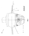
- runner unit 100 includes a runner body 2, where a plurality of blades 3 is rotatably fitted.
- rotor body 2 comprises four blades, but it will be appreciated that rotor body 2 may comprise only one blade.
- Runner body 2 ends with a tip portion 21.
- Runner body 2 is hollow inside and includes an internal mechanism, generally indicated with numeral 40, which acts on the blades 3 to cause rotation thereof about an axis R, arranged substantially perpendicular to an external surface of the runner body 2 where the blade 3 is fitted.
- axis R may have any inclinations with respect to the external surface of the runner body 2 where the blade is fitted, depending on the particular design selected.
- the pitch of the blades 3 is regulated by mechanism 40 which depends on the operative conditions to maximise efficiency of the energy conversion process.
- a gap existing between an inner edge 31 of the blade 3 and the end tip portion 21 is defined and depends on the chosen geometry of runner unit 100.
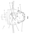
- Runner unit 1 comprises a runner body 2 where a plurality of blades 3 is rotatably fitted and rotatable about the axis R.
- runner body 2 in the present non-limiting example comprises four blades, but it will be appreciated that it could include one or several blades.
- Runner body 2 terminates with an end tip portion 21.
- the flow of water along the runner unit 1 causes the runner body 2, which is integral, usually by bolting, to a shaft 11, to rotate about a central axis Z for the production of electricity.
- the end tip portion 21 is movable, relative to the rotor body 2 and the shaft 11, between an extended, or downwards, operative position and a retracted, or inwards, operative position.
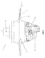
- figure 2 shows on the same section the two different positions: on the right side the end tip portion 21 is extracted and protrudes downwards (, whilst on the left side it is shown the runner unit 1 having the end tip portion 21 in the fully retracted position.
- the existing gap between the inner edge 31 of the blade 3 and the end tip portion 21 may be advantageously adjusted, depending on the operative flow condition, to maximise efficiency.
- runner unit 1 comprises an internal mechanism 4 which is interposed between the rotatable blade 3 and the end tip portion 21. More in particular, mechanism 4 is configured such to act on the blade and cause its rotation about the axis R. Preferably, mechanism 4 may also be associated to the end tip portion 21, as it will be described below, and configured to adjust the position of the latter based on an angle of rotation of blade 3.
- Mechanism 4 includes a piston 41 (visible in figure 2 ) which is adapted to reciprocate along the shaft 11 of the runner unit 1.
- the movement of the piston 41 may be enabled by means of an oil-type drive (not shown).
- Piston 41 includes an upstream portion 411 which is coupled to the blade 3 to cause its rotation, and a downstream portion 412 which is integral to the end tip portion 21.
- Blade 3 is rotatably fitted on the runner body 2 by means of a trunnion portion which comprises a lever 32.
- Lever 32 comprises a pin 321 arranged eccentric with respect to the blade axis of rotation R (which in this preferred embodiment is substantially perpendicular to the section plane of the figure and thus not visible), which is in turn connected to the piston 41 by means of a link member 322..
- the movement of the piston 41along the shaft 11 causes the lever 32 to rotate about blade axis R, and thus such rotation is transferred to blade 3.
- End tip portion 21 comprises an annular seal member 211 which is coupled to the downstream portion 412 of the piston 41.
- the annular seal member 211 is located inside the runner body 2.
- the pitch of the blade 3 is such that the piston 41 is in an upward location.
- movement of the end tip portion 21 may be achieved with a separated servomotor, not directly linked to mechanism associated to the rotation of the blades.
Landscapes
- Engineering & Computer Science (AREA)
- Chemical & Material Sciences (AREA)
- Combustion & Propulsion (AREA)
- Mechanical Engineering (AREA)
- General Engineering & Computer Science (AREA)
- Life Sciences & Earth Sciences (AREA)
- General Life Sciences & Earth Sciences (AREA)
- Oceanography (AREA)
- Hydraulic Turbines (AREA)
Priority Applications (4)
| Application Number | Priority Date | Filing Date | Title |
|---|---|---|---|
| EP15290238.3A EP3147497A1 (de) | 2015-09-22 | 2015-09-22 | Läufereinheit für eine wasserturbine |
| US15/272,489 US20170082084A1 (en) | 2015-09-22 | 2016-09-22 | Runner unit for a hydro turbine |
| CN201610839877.9A CN106930885A (zh) | 2015-09-22 | 2016-09-22 | 用于水力涡轮的转轮单元 |
| BR102016021765A BR102016021765A2 (pt) | 2015-09-22 | 2016-09-22 | unidade de roda para uma hidroturbina e hidroturbina |
Applications Claiming Priority (1)
| Application Number | Priority Date | Filing Date | Title |
|---|---|---|---|
| EP15290238.3A EP3147497A1 (de) | 2015-09-22 | 2015-09-22 | Läufereinheit für eine wasserturbine |
Publications (1)
| Publication Number | Publication Date |
|---|---|
| EP3147497A1 true EP3147497A1 (de) | 2017-03-29 |
Family
ID=54291206
Family Applications (1)
| Application Number | Title | Priority Date | Filing Date |
|---|---|---|---|
| EP15290238.3A Withdrawn EP3147497A1 (de) | 2015-09-22 | 2015-09-22 | Läufereinheit für eine wasserturbine |
Country Status (4)
| Country | Link |
|---|---|
| US (1) | US20170082084A1 (de) |
| EP (1) | EP3147497A1 (de) |
| CN (1) | CN106930885A (de) |
| BR (1) | BR102016021765A2 (de) |
Citations (6)
| Publication number | Priority date | Publication date | Assignee | Title |
|---|---|---|---|---|
| CH310028A (de) * | 1953-03-13 | 1955-09-30 | Escher Wyss Ag | Aus Kaplanturbine und Generator bestehender hydroelektrischer Maschinensatz. |
| JPS50101731U (de) * | 1974-01-25 | 1975-08-22 | ||
| JPH0475161U (de) * | 1990-11-09 | 1992-06-30 | ||
| EP1624184A2 (de) * | 2004-08-05 | 2006-02-08 | Voith Siemens Hydro Power Generation GmbH & Co. KG | Hydraulische Turbine oder Pumpturbine |
| CN102410127A (zh) * | 2011-10-27 | 2012-04-11 | 浙江大学 | 泄水锥装置 |
| WO2014166663A1 (de) * | 2013-04-08 | 2014-10-16 | Voith Patent Gmbh | Vorrichtung und verfahren zur reduktion von druckschwankungen im saugrohr einer wasser-turbine oder -pumpe oder -pumpturbine |
Family Cites Families (3)
| Publication number | Priority date | Publication date | Assignee | Title |
|---|---|---|---|---|
| US1950775A (en) * | 1932-12-15 | 1934-03-13 | James Leffel & Company | Hydraulic turbine |
| US2701313A (en) * | 1953-03-13 | 1955-02-01 | Escher Wyss Ag | Air supply to turbine runners of hydroelectric power plants |
| JP5956885B2 (ja) * | 2012-09-19 | 2016-07-27 | 株式会社東芝 | 水力機械およびその運転方法 |
-
2015
- 2015-09-22 EP EP15290238.3A patent/EP3147497A1/de not_active Withdrawn
-
2016
- 2016-09-22 CN CN201610839877.9A patent/CN106930885A/zh active Pending
- 2016-09-22 BR BR102016021765A patent/BR102016021765A2/pt not_active Application Discontinuation
- 2016-09-22 US US15/272,489 patent/US20170082084A1/en not_active Abandoned
Patent Citations (6)
| Publication number | Priority date | Publication date | Assignee | Title |
|---|---|---|---|---|
| CH310028A (de) * | 1953-03-13 | 1955-09-30 | Escher Wyss Ag | Aus Kaplanturbine und Generator bestehender hydroelektrischer Maschinensatz. |
| JPS50101731U (de) * | 1974-01-25 | 1975-08-22 | ||
| JPH0475161U (de) * | 1990-11-09 | 1992-06-30 | ||
| EP1624184A2 (de) * | 2004-08-05 | 2006-02-08 | Voith Siemens Hydro Power Generation GmbH & Co. KG | Hydraulische Turbine oder Pumpturbine |
| CN102410127A (zh) * | 2011-10-27 | 2012-04-11 | 浙江大学 | 泄水锥装置 |
| WO2014166663A1 (de) * | 2013-04-08 | 2014-10-16 | Voith Patent Gmbh | Vorrichtung und verfahren zur reduktion von druckschwankungen im saugrohr einer wasser-turbine oder -pumpe oder -pumpturbine |
Also Published As
| Publication number | Publication date |
|---|---|
| BR102016021765A2 (pt) | 2017-03-28 |
| CN106930885A (zh) | 2017-07-07 |
| US20170082084A1 (en) | 2017-03-23 |
Similar Documents
| Publication | Publication Date | Title |
|---|---|---|
| AU2012334378B2 (en) | Turbine for a hydroelectric power plant, and hydroelectric power plant | |
| US8317469B2 (en) | Wind turbine shroud | |
| US10247166B2 (en) | Device for reversing a blade of a runner unit | |
| PH12012500996A1 (en) | Turbine | |
| WO2013106075A3 (en) | Novel systems for increasing efficiency and power output of in-conduit hydroelectric power system and turbine | |
| KR102024907B1 (ko) | 벌브형 수차의 블레이드 개폐 조절장치 | |
| CN104234910A (zh) | 改造能量转换设备的方法和改造的能量转换设备 | |
| KR20150097519A (ko) | 안내되거나 구속되지 않은 수류의 에너지를 이용하는 수력 발전소 | |
| US20160025062A1 (en) | Water turbine | |
| KR100776319B1 (ko) | 수직축 방식의 풍력발전장치 | |
| CA2969485C (en) | Hydraulic turbomachine | |
| US20170082084A1 (en) | Runner unit for a hydro turbine | |
| CN105863924A (zh) | 一种电力设备的混流式水轮机 | |
| US10961978B2 (en) | Turbine unit for hydraulic installation | |
| CN103790774B (zh) | 一种可调迎风面积的垂直轴风力机 | |
| US10598144B2 (en) | Device for reversing a blade of a runner unit | |
| US20210062785A1 (en) | Foldable blade for a wind turbine and method of use | |
| US1954193A (en) | Hydraulic turbine | |
| US20250084824A1 (en) | Impeller for wind turbines | |
| SĂULESCU et al. | KINEMATIC AND STATIC MODELLING OF THE ADJUSTABLE-BLADE MECHANISM USED IN KAPLAN TURBINES | |
| RU120725U1 (ru) | Ветроэнергетическая установка | |
| KR20130074317A (ko) | 풍력발전기 | |
| HK40105886B (en) | Impeller for wind turbines |
Legal Events
| Date | Code | Title | Description |
|---|---|---|---|
| PUAI | Public reference made under article 153(3) epc to a published international application that has entered the european phase |
Free format text: ORIGINAL CODE: 0009012 |
|
| AK | Designated contracting states |
Kind code of ref document: A1 Designated state(s): AL AT BE BG CH CY CZ DE DK EE ES FI FR GB GR HR HU IE IS IT LI LT LU LV MC MK MT NL NO PL PT RO RS SE SI SK SM TR |
|
| AX | Request for extension of the european patent |
Extension state: BA ME |
|
| RAP1 | Party data changed (applicant data changed or rights of an application transferred) |
Owner name: GE RENEWABLE TECHNOLOGIES |
|
| 17P | Request for examination filed |
Effective date: 20170929 |
|
| RBV | Designated contracting states (corrected) |
Designated state(s): AL AT BE BG CH CY CZ DE DK EE ES FI FR GB GR HR HU IE IS IT LI LT LU LV MC MK MT NL NO PL PT RO RS SE SI SK SM TR |
|
| 17Q | First examination report despatched |
Effective date: 20180611 |
|
| STAA | Information on the status of an ep patent application or granted ep patent |
Free format text: STATUS: THE APPLICATION IS DEEMED TO BE WITHDRAWN |
|
| 18D | Application deemed to be withdrawn |
Effective date: 20181222 |