EP3147528A1 - Dispositif de mesure et procede de detection d'un moment de ponçage - Google Patents
Dispositif de mesure et procede de detection d'un moment de ponçage Download PDFInfo
- Publication number
- EP3147528A1 EP3147528A1 EP16001826.3A EP16001826A EP3147528A1 EP 3147528 A1 EP3147528 A1 EP 3147528A1 EP 16001826 A EP16001826 A EP 16001826A EP 3147528 A1 EP3147528 A1 EP 3147528A1
- Authority
- EP
- European Patent Office
- Prior art keywords
- carrier part
- measuring
- brake
- pad
- force
- Prior art date
- Legal status (The legal status is an assumption and is not a legal conclusion. Google has not performed a legal analysis and makes no representation as to the accuracy of the status listed.)
- Granted
Links
Images


Classifications
-
- F—MECHANICAL ENGINEERING; LIGHTING; HEATING; WEAPONS; BLASTING
- F16—ENGINEERING ELEMENTS AND UNITS; GENERAL MEASURES FOR PRODUCING AND MAINTAINING EFFECTIVE FUNCTIONING OF MACHINES OR INSTALLATIONS; THERMAL INSULATION IN GENERAL
- F16D—COUPLINGS FOR TRANSMITTING ROTATION; CLUTCHES; BRAKES
- F16D65/00—Parts or details
- F16D65/02—Braking members; Mounting thereof
- F16D65/04—Bands, shoes or pads; Pivots or supporting members therefor
- F16D65/092—Bands, shoes or pads; Pivots or supporting members therefor for axially-engaging brakes, e.g. disc brakes
-
- F—MECHANICAL ENGINEERING; LIGHTING; HEATING; WEAPONS; BLASTING
- F16—ENGINEERING ELEMENTS AND UNITS; GENERAL MEASURES FOR PRODUCING AND MAINTAINING EFFECTIVE FUNCTIONING OF MACHINES OR INSTALLATIONS; THERMAL INSULATION IN GENERAL
- F16D—COUPLINGS FOR TRANSMITTING ROTATION; CLUTCHES; BRAKES
- F16D55/00—Brakes with substantially-radial braking surfaces pressed together in axial direction, e.g. disc brakes
- F16D55/02—Brakes with substantially-radial braking surfaces pressed together in axial direction, e.g. disc brakes with axially-movable discs or pads pressed against axially-located rotating members
- F16D55/22—Brakes with substantially-radial braking surfaces pressed together in axial direction, e.g. disc brakes with axially-movable discs or pads pressed against axially-located rotating members by clamping an axially-located rotating disc between movable braking members, e.g. movable brake discs or brake pads
-
- G—PHYSICS
- G01—MEASURING; TESTING
- G01L—MEASURING FORCE, STRESS, TORQUE, WORK, MECHANICAL POWER, MECHANICAL EFFICIENCY, OR FLUID PRESSURE
- G01L5/00—Apparatus for, or methods of, measuring force, work, mechanical power, or torque, specially adapted for specific purposes
- G01L5/28—Apparatus for, or methods of, measuring force, work, mechanical power, or torque, specially adapted for specific purposes for testing brakes
-
- F—MECHANICAL ENGINEERING; LIGHTING; HEATING; WEAPONS; BLASTING
- F16—ENGINEERING ELEMENTS AND UNITS; GENERAL MEASURES FOR PRODUCING AND MAINTAINING EFFECTIVE FUNCTIONING OF MACHINES OR INSTALLATIONS; THERMAL INSULATION IN GENERAL
- F16D—COUPLINGS FOR TRANSMITTING ROTATION; CLUTCHES; BRAKES
- F16D66/00—Arrangements for monitoring working conditions, e.g. wear, temperature
- F16D2066/005—Force, torque, stress or strain
Definitions
- the invention relates to a measuring device for detecting a grinding torque between a brake disc and a brake pad of a disc brake, with a lining carrier for supporting the brake pad and a force transducer for measuring a force resulting from the grinding torque and acting on the brake pad force.
- the invention further relates to a disc brake, in particular for a motor vehicle, with a brake disc and a brake pad, wherein the brake disc and the brake pad are movable relative to each other, and a measuring device for detecting a grinding torque between the brake disc and the brake pad.
- the invention relates to a method for detecting an abrasive torque between a brake disc and a brake pad of a disc brake.
- Modern disc brakes for use in motor vehicles usually have a brake disc and two brake pads which are movable relative to the brake disc and which are arranged on opposite sides of the brake disc.
- the brake pads are each supported by a lining carrier and pressed in the application by means of a brake caliper to the brake disc.
- a brake caliper of the disc brake in the axial direction of the brake disc for example floating, stored.
- an unintentional grinding torque is applied between the brake disk and a brake pad of the disk brake.
- Such a grinding torque causes a braking effect and thus leads to increased fuel consumption and to additional wear of the brake pads and the brake disc.
- the known measuring devices and methods are, however, unsatisfactory in their ability to detect low grinding torques in a "lower" measuring range of about 5 Nm or less.
- the biasing forces exerted by the hold-down spring on the brake pad carrier or the brake pad are overcome before a measurement can take place by means of the measuring module.
- this measurement concept only allows the detection of grinding torque in a range of about 5 Nm.
- the invention was therefore an object of the invention to provide a way to detect the lowest possible grinding torque between a brake disc and a brake pad of a disc brake, in particular a grinding torque in a range of less than 5 Nm.
- the object is achieved by a measuring device of the aforementioned type, wherein the lining carrier has a first lining carrier part and a second lining carrier part and the force measuring transducer is adapted to detect the force acting between the first lining carrier part and the second lining carrier part.
- the invention makes use of the knowledge that during the force measurement between the first pad carrier part and the second pad carrier part interaction forces arise. These arise regardless of whether or that any biasing forces, such as the biasing force of the hold-down spring, must be overcome. Consequently, a low grinding torque between the brake disc and the brake pad of the disc brake can be detected, since the presence of a grinding torque immediately leads to a compressive force between the first pad carrier part and the second pad carrier part. Thus, an extremely low grinding torque between the brake disc and the brake pad of the disc brake can be determined by the measuring device according to the invention, in particular a grinding torque in a measuring range of less than 5 Nm.
- the load cell is at least partially disposed within the lining carrier.
- at least a part of the force measuring transducer is arranged within the first lining carrier part.
- at least a part of the force measuring transducer is arranged in the second lining carrier part.
- the force transducer is designed as a piezoelectric force transducer, in particular as a capacitive force transducer.
- the first lining carrier part and the second lining carrier part are movable relative to one another. Because the first pad carrier part and the second pad carrier part are movable relative to one another, the measurement of the force measuring transducer can be influenced. In particular, in this way, the force acting on the force transducer can be limited and / or eliminated, so that damage to the force transducer is prevented by excessive stress.
- the first lining carrier and the second lining carrier are movable relative to one another in only one direction, this direction corresponding to the force-receiving direction of the force measuring transducer.
- first pad carrier part and the second pad carrier part are additionally movable perpendicular to the force-receiving direction of the force measuring transducer relative to each other.
- a relative movement between the first pad carrier part and the second pad carrier part is preferably initiated by initiating a braking operation and thus by pressing the brake pad against the brake disk.
- a further relative movement between the first pad carrier part and the second pad carrier part is preferably initiated by termination or interruption of a braking operation and thus by canceling or reducing the contact pressure of the brake pad on the brake disk.
- the first lining carrier part has a first recess, into which at least part of the second lining carrier part is received.
- this part of the second lining carrier part extends into the first recess of the first lining carrier part.
- the second lining carrier part is preferably corresponding to the first recess of the first lining carrier part educated.
- the recess of the first pad carrier part and the second pad carrier part are adapted to one another such that the first pad carrier part and the second pad carrier part are movable relative to each other.
- a movement clearance results between the first lining carrier part and the second lining carrier part.
- the first lining carrier part has a second recess in which at least part of the force measuring transducer is received.
- the second lining carrier part also has a recess into which at least part of the force measuring transducer is received.
- the load cell is completely received in the first pad carrier part and the second pad carrier part.
- the measuring device is further developed advantageously in that the first lining carrier part has a contact surface for the force measuring transducer.
- the contact surface of the first lining carrier part faces the first recess.
- the contact surface extends along the contour of the first recess.
- the contact surface is limited on one side of the contour of the recess.
- the first recess of the first lining carrier part has an inner contour and the second lining carrier part has an outer contour, wherein the shape of the outer contour essentially corresponds to the shape of the inner contour and the size of the outer contour and the size of the inner contour play a movement between define the first pad carrier part and the second pad carrier part.
- the size of the outer contour and the size of the inner contour define a play of motion in a range of 0.05 mm to 4 mm, particularly preferably a play of movement in a range of 0.2 mm to 1 mm.
- the first lining carrier part and the second lining carrier part are connected to one another by screwed transverse struts such that a relative movement between the first lining carrier part and the second lining carrier part is prevented or at least limited parallel to the central axis of the brake disk.
- the force measuring transducer is aligned and aligned for measuring in a measuring direction, wherein the measuring direction is substantially tangential to a central axis of the brake disc.
- the force measuring transducer is arranged in a side region of the lining carrier, so that the measuring direction can deviate in the range of 0 to 5 degrees from the tangential direction of the center axis of the brake disk.
- tangential to a center axis of the brake disk is understood here as the direction which is perpendicular to the central axis of the brake disk and perpendicular to a radial axis extending from the central axis.
- the force measuring transducer is formed as part of a measuring arrangement, wherein the measuring arrangement is attached to the first lining carrier part or the second lining carrier part and the force measuring transducer is movable in the measuring direction within the measuring arrangement.
- the measuring arrangement further comprises a sliding block, which is also movable within the measuring arrangement in the measuring direction of the Kraftmessaufillon and is adapted to transmit the force from the first pad carrier part or the second pad carrier part to the force transducer.
- the measuring arrangement further comprises an insert and a bore in which a retaining ring is arranged within the measuring arrangement for limiting the movement of the force measuring transducer.
- the measuring arrangement has a spring element which acts on the force measuring transducer and an approximation of the first lining carrier part and the second lining carrier part counteracts each other.
- the spring element In the installed state and at a maximum spacing of the first lining carrier part from the second lining carrier part, the spring element has a zero position. In the zero position, the spring element preferably exerts no biasing force on the load cell.
- the spring element biases the load cell against the second pad carrier part.
- the measuring arrangement preferably has an insert connected to the second lining carrier part, and the spring element biases the force measuring sensor against the insert.
- the spring element already exerts a biasing force on the load cell in the zero position.
- the spring element biases the load cell against the first pad carrier part, in particular against the contact surface of the first pad carrier part.
- the spring element is preferably designed as a disc spring assembly and is supported on a thrust washer which presses against the retaining ring within the bore.
- the measuring device according to the invention is further developed advantageously in that the measuring arrangement has one or more mounting holes and the measuring arrangement is screwed by means of one or more screws with the first pad carrier part or the second pad carrier part.
- a measuring device is preferred in which the force measuring transducer has a predefined measuring range, the sum of the preload force and the reaction force resulting from the resilience of the spring element and the maximum play between the first pad carrier part and the second brake pad part being within the predefined measuring range.
- the predefined measuring range is preferably 0 to 1000 N, more preferably 0 to 500 N, and particularly preferably 0 to 50 N.
- the maximum force acting on the load cell force is limited to the sum of the biasing force and resulting from the flexibility of the spring element and the maximum play between the first pad carrier part and the second pad carrier part reaction force, so that damage or malfunction of the force transducer is avoided ,
- a further preferred embodiment of the measuring device has an evaluation unit, which is signal-conducting connected to the force transducer.
- the evaluation unit is set up to determine the grinding torque between the brake disk and the brake pad of the disk brake on the basis of a signal provided by the load cell.
- calculation parameters are stored in the evaluation unit, which are used to determine the grinding torque between the brake disc and the brake pad of the disc brake.
- these calculation parameters include an effective radius r.
- two measuring devices are used, for example, each in a brake pad in accordance with the preferred embodiments described herein.
- the two bearing carrier carrying the respective measuring device are by means of the respective brake pads preferably on both sides of a brake disc.
- the grinding torque is calculated as the sum of the two individual moments. Since the same effective radius does not necessarily have to be present for both sides, then several effective radii r 1 and r 2 are applied.
- the grinding torque with M, the force detected by the load cell of one measuring device as F, the force detected by the load cell of the first measuring device (of two) are F 1
- the force detected by the force measuring element of the second measuring device is two referred to as F 2 .
- the problem underlying the invention is further achieved by a disc brake of the type mentioned, wherein the measuring device is designed for detecting the grinding torque between the brake disc and the brake pad according to one of the embodiments described above.
- the grinding torque with M, the force detected by the load cell of a first measuring device as F 1 and the force detected by the load cell of a second measuring device are designated as F 2 .
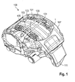
- Fig. 1 The disc brake 100 according to the invention, which is designed for use in a motor vehicle, a brake disc 105 (partially shown) and two arranged on opposite sides of the brake disc 105 brake pads 103, wherein the brake disc 105 and the brake pads 103 are movable relative to each other. At least one Brake lining 103 is supported by a lining carrier, which is part of a measuring device 1 according to the invention.
- the disc brake 100 further includes a caliper 107 which slides axially on guide pins of a brake carrier 111.
- the brake pads 103 are guided and supported axially displaceably in the brake carrier 111.
- the brake pads 103 are held by a hold-down bracket 109 and by hold-down springs 101.
- the measuring device 1 serves to detect an abrasive torque between a brake disc and a brake pad 103 of a disc brake.
- the measuring device 1 comprises a lining carrier 3a, 3b for supporting the brake lining 103 and a force measuring transducer 5 (FIG. Fig. 5 ) for measuring a resulting from the grinding torque and acting on the brake pad 103 force.
- the lining carrier 3a, 3b has a first lining carrier part 3a and a second lining carrier part 3b, wherein the force measuring transducer 5 is adapted to detect the force acting between the first lining carrier part 3a and the second lining carrier part 3b.
- a part of the force measuring transducer 5 is arranged within the lining carrier parts 3a and 3b.
- the first pad carrier part 3a and the second pad carrier part 3b are movable relative to one another in the measuring direction of the force measuring transducer and interconnected by transverse struts 35 such that a relative movement between the first pad carrier part 3a and the second pad carrier part 3b is parallel to a center axis of the brake disc which is substantially perpendicular extends to the measuring direction of the force measuring 5, is prevented or at least limited.
- the cross struts 35 act positively with lateral lugs (reference numeral 37, FIG. 3 ) of the second lining carrier part 3b together, so that by adjusting screw 33, the movement play parallel to the central axis of the brake disk between the first lining carrier part 3a and the second Adjusting lining carrier part 3b.
- the screw 33 are each formed by a screw which engages in a threaded portion of the first pad carrier part 3a.
- Fig. 3 shows that the first pad carrier part 3a has a first recess 7, in which, in the assembled state, a part of the second pad carrier part 3b is accommodated.
- the first recess 7 of the first lining carrier part 3a has an inner contour 13.
- the second lining carrier part 3b has an outer contour 15.
- the shape of the outer contour 15 substantially corresponds to the shape of the inner contour 13, wherein the size of the outer contour 15 and the size of the inner contour 13 define a movement play between the first pad carrier part 3a and the second pad carrier part 3b.
- a section of the inner contour 13 of the first lining carrier part 3a forms a contact surface 11 for the force measuring transducer (not shown), wherein the contact surface 11 faces the first recess 7.
- the illustration also shows the lateral lugs 37 of the second lining support part 3b, which with the cross struts 35 (see Fig. 2 ) cooperate positively.
- the brake lining 103 is fastened to the second lining carrier part 3b.
- a second recess 8 extends in the direction away from the second lining carrier part 3b.
- the first recess 7 and the second recess 8 in the first pad support part 3a together form a through hole in the first pad support part 3a.
- the shape of the brake pad 103 is designed to cooperate with a hold-down spring 101.
- the first lining carrier part 3a has a first recess 7 (FIG. Fig. 3 ) and second recess 8, which together form a through hole.
- the second lining carrier part 3b likewise has a recess 9, which adjoins the through hole of the first lining carrier part 3a and projects in the direction of the brake disk or the brake lining 103 (FIG. Fig. 2 ).
- the recess 9 of the second lining carrier part 3b is suitable for receiving a measuring arrangement 19 (FIG. Fig. 5 ), wherein the measuring arrangement 19 the force transducer 5 ( Figure 5 ).
- the recess 9 of the second lining carrier part 3b comprises two cylindrical sections of different diameters. Furthermore, the recess 9 of the second lining carrier part 3b comprises two threaded bores for receiving screws 29a, b (FIG. Fig. 5 ) for fastening the measuring arrangement 19.
- the force measuring transducer to be arranged in the recess 9 of the second lining carrier part 3b is aligned and aligned for measuring in a measuring direction, the measuring direction being essentially tangential to the central axis 113 of the brake disk 105.
- the force measuring transducer of the measuring arrangement 19 is arranged in a side region of the lining carrier 3b so that the central axis 114 of the measuring direction 17 can deviate in the range of 0 to 5 degrees from the tangential direction of the center axis 113 of the brake disk 105.
- the distance between the center axis 113 of the brake disk 105 and the central axis 114 of the measuring direction 17 corresponds to the effective radius r.
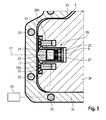
- the sectional view from Fig. 5 shows that in the recess 9, a measuring arrangement 19 is arranged.
- the measuring arrangement 19 comprises an insert 20, a sliding block 23, which interacts with the force measuring transducer 5.
- the force measuring transducer 5 has a predefined measuring range and is biased by a spring element 21 against the insert 20 of the measuring arrangement 19.
- the sum of the biasing force of the spring element 21 and the resulting from the flexibility of the spring element 21 and the maximum play between the first pad carrier part 3a and the second pad carrier part 3b reaction force is within the predefined measuring range of the Kraftmessaufsmellings 5.
- the spring element 21 is connected via a pressure washer 25 at a Circlip 27 secured axially.
- the sliding block 23 and the load cell 5 are axially displaceable in the measuring direction 17 within a bore of the measuring arrangement 19.
- the measuring arrangement 19 is fastened to the second lining carrier part 3b by means of screws 29a, 29b.
- the measuring device 1 further has an evaluation unit 31, which is signal-conducting connected to the Kraftmessauf choir 5, wherein the evaluation unit is adapted to on the basis of one of the force transducer 5 for Provided signal to determine the grinding torque between the brake disc and the brake pad 103 of the disc brake 100.
Landscapes
- Engineering & Computer Science (AREA)
- General Engineering & Computer Science (AREA)
- Mechanical Engineering (AREA)
- Physics & Mathematics (AREA)
- General Physics & Mathematics (AREA)
- Braking Arrangements (AREA)
Applications Claiming Priority (1)
| Application Number | Priority Date | Filing Date | Title |
|---|---|---|---|
| DE102015011951.6A DE102015011951A1 (de) | 2015-09-18 | 2015-09-18 | Messeinrichtung und Verfahren zur Erfassung eines Schleifmoments |
Publications (2)
| Publication Number | Publication Date |
|---|---|
| EP3147528A1 true EP3147528A1 (fr) | 2017-03-29 |
| EP3147528B1 EP3147528B1 (fr) | 2020-07-22 |
Family
ID=56740753
Family Applications (1)
| Application Number | Title | Priority Date | Filing Date |
|---|---|---|---|
| EP16001826.3A Active EP3147528B1 (fr) | 2015-09-18 | 2016-08-19 | Dispositif de mesure et procede de detection d'un moment de ponçage |
Country Status (2)
| Country | Link |
|---|---|
| EP (1) | EP3147528B1 (fr) |
| DE (1) | DE102015011951A1 (fr) |
Families Citing this family (1)
| Publication number | Priority date | Publication date | Assignee | Title |
|---|---|---|---|---|
| DE102023116542A1 (de) * | 2023-06-23 | 2024-12-24 | Zf Cv Systems Europe Bv | Messeinrichtung zum Erfassen eines Schleifmoments zwischen einer Bremsscheibe und wenigstens einem Bremsbelag |
Citations (5)
| Publication number | Priority date | Publication date | Assignee | Title |
|---|---|---|---|---|
| DE2539596A1 (de) * | 1974-09-06 | 1976-03-25 | Bromsregulator Svenska Ab | Verfahren und vorrichtung zum dynamischen messen von bremskraeften |
| DE102006058882A1 (de) * | 2006-12-13 | 2008-06-19 | Siemens Ag | Separate Erfassung von Zuspann- und Reibkräften an einer Bremse |
| JP2011190865A (ja) * | 2010-03-15 | 2011-09-29 | Akebono Brake Ind Co Ltd | ブレーキトルク測定装置 |
| WO2014184112A1 (fr) | 2013-05-13 | 2014-11-20 | Knorr-Bremse Systeme für Nutzfahrzeuge GmbH | Frein à disque comportant un dispositif de mesure du couple de patinage et procédé correspondant |
| EP2895767A1 (fr) * | 2013-04-17 | 2015-07-22 | ITT Italia S.r.l. | Procédé de fabrication d'un élément de freinage avec détecteur intégré, en particulier une plaquette de frein, d'une plaquette de frein ayant un détecteur intégré, système de freinage de véhicule et procédé associé |
-
2015
- 2015-09-18 DE DE102015011951.6A patent/DE102015011951A1/de not_active Withdrawn
-
2016
- 2016-08-19 EP EP16001826.3A patent/EP3147528B1/fr active Active
Patent Citations (5)
| Publication number | Priority date | Publication date | Assignee | Title |
|---|---|---|---|---|
| DE2539596A1 (de) * | 1974-09-06 | 1976-03-25 | Bromsregulator Svenska Ab | Verfahren und vorrichtung zum dynamischen messen von bremskraeften |
| DE102006058882A1 (de) * | 2006-12-13 | 2008-06-19 | Siemens Ag | Separate Erfassung von Zuspann- und Reibkräften an einer Bremse |
| JP2011190865A (ja) * | 2010-03-15 | 2011-09-29 | Akebono Brake Ind Co Ltd | ブレーキトルク測定装置 |
| EP2895767A1 (fr) * | 2013-04-17 | 2015-07-22 | ITT Italia S.r.l. | Procédé de fabrication d'un élément de freinage avec détecteur intégré, en particulier une plaquette de frein, d'une plaquette de frein ayant un détecteur intégré, système de freinage de véhicule et procédé associé |
| WO2014184112A1 (fr) | 2013-05-13 | 2014-11-20 | Knorr-Bremse Systeme für Nutzfahrzeuge GmbH | Frein à disque comportant un dispositif de mesure du couple de patinage et procédé correspondant |
Also Published As
| Publication number | Publication date |
|---|---|
| DE102015011951A1 (de) | 2017-03-23 |
| EP3147528B1 (fr) | 2020-07-22 |
Similar Documents
| Publication | Publication Date | Title |
|---|---|---|
| EP2981796B1 (fr) | Dispositif de mesure de forces | |
| EP0421066B1 (fr) | Procédé et dispositif pour évaluer approximativement la température moyenne d'un élément de frein | |
| DE102012007118B4 (de) | Vorrichtung zur Messung von Restbremsmomenten einer Scheibenbremse eines Kraftfahrzeugs | |
| EP1800809A1 (fr) | Dispositif de freinage pour un actionneur de robot et méthode pour surveiller l'état d'un frein | |
| DE10350085B4 (de) | Messeinrichtung für eine elektro-mechanische Bremse | |
| WO2008071578A1 (fr) | Enregistrement séparé des forces d'application et de friction sur un frein | |
| EP3356691A1 (fr) | Système de palier à roulement muni d'un dispositif extensométrique | |
| EP3093641B1 (fr) | Procédé de détermination d'une force de traction axiale appliquée à un composant | |
| EP1242797B1 (fr) | Capteur de force a element d'actionnement integre | |
| DE112019005355T5 (de) | Elektrische bremse | |
| DE102011002567A1 (de) | Scheibenbremse sowie Verfahren zur Ermittlung einer wirkenden Bremskraft oder eines wirkenden Bremsmoments | |
| DE10254041B4 (de) | Verfahren und Vorichtung zur Störungsfrüherkennung bei Kreiselpumpen | |
| DE102014106184A1 (de) | Detektiervorrichtung für Radkraftkomponenten | |
| EP3147528A1 (fr) | Dispositif de mesure et procede de detection d'un moment de ponçage | |
| DE102007029927A1 (de) | Scheibenbremse für ein Kraftfahrzeug und Gehäuse hierfür | |
| DE3212759C2 (fr) | ||
| WO2021008642A1 (fr) | Dispositif de freinage et/ou de serrage comprenant un logement divisé d'une seule pièce et module de capteur | |
| DE102019104790A1 (de) | Bauteilanordnung mit einem Kraftmessbolzen | |
| DE102018107320B4 (de) | Kraftmesseinrichtung | |
| DE102018113771B4 (de) | Messvorrichtung zur Ermittlung von Zug- und Druckkräften, insbesondere Wägezelle | |
| DE102016110577A1 (de) | Passfeder zur Bestimmung eines übertragenen Drehmomentes | |
| DE112021007057T5 (de) | Drehmomentsensor | |
| DE102016111881A1 (de) | Messaufnehmer zur Messung von Verformungen und Bremse mit einem solchen Messaufnehmer | |
| EP1336829A2 (fr) | Dispositif de mesure de la force axiale dans un arbre | |
| EP3913347A1 (fr) | Dispositif de mesure pour détecter la déformation d'un tuyau en élastomère |
Legal Events
| Date | Code | Title | Description |
|---|---|---|---|
| PUAI | Public reference made under article 153(3) epc to a published international application that has entered the european phase |
Free format text: ORIGINAL CODE: 0009012 |
|
| STAA | Information on the status of an ep patent application or granted ep patent |
Free format text: STATUS: THE APPLICATION HAS BEEN PUBLISHED |
|
| AK | Designated contracting states |
Kind code of ref document: A1 Designated state(s): AL AT BE BG CH CY CZ DE DK EE ES FI FR GB GR HR HU IE IS IT LI LT LU LV MC MK MT NL NO PL PT RO RS SE SI SK SM TR |
|
| AX | Request for extension of the european patent |
Extension state: BA ME |
|
| STAA | Information on the status of an ep patent application or granted ep patent |
Free format text: STATUS: REQUEST FOR EXAMINATION WAS MADE |
|
| 17P | Request for examination filed |
Effective date: 20170929 |
|
| RBV | Designated contracting states (corrected) |
Designated state(s): AL AT BE BG CH CY CZ DE DK EE ES FI FR GB GR HR HU IE IS IT LI LT LU LV MC MK MT NL NO PL PT RO RS SE SI SK SM TR |
|
| STAA | Information on the status of an ep patent application or granted ep patent |
Free format text: STATUS: EXAMINATION IS IN PROGRESS |
|
| 17Q | First examination report despatched |
Effective date: 20190717 |
|
| GRAP | Despatch of communication of intention to grant a patent |
Free format text: ORIGINAL CODE: EPIDOSNIGR1 |
|
| STAA | Information on the status of an ep patent application or granted ep patent |
Free format text: STATUS: GRANT OF PATENT IS INTENDED |
|
| INTG | Intention to grant announced |
Effective date: 20200309 |
|
| GRAS | Grant fee paid |
Free format text: ORIGINAL CODE: EPIDOSNIGR3 |
|
| GRAA | (expected) grant |
Free format text: ORIGINAL CODE: 0009210 |
|
| STAA | Information on the status of an ep patent application or granted ep patent |
Free format text: STATUS: THE PATENT HAS BEEN GRANTED |
|
| AK | Designated contracting states |
Kind code of ref document: B1 Designated state(s): AL AT BE BG CH CY CZ DE DK EE ES FI FR GB GR HR HU IE IS IT LI LT LU LV MC MK MT NL NO PL PT RO RS SE SI SK SM TR |
|
| REG | Reference to a national code |
Ref country code: GB Ref legal event code: FG4D Free format text: NOT ENGLISH |
|
| REG | Reference to a national code |
Ref country code: CH Ref legal event code: EP |
|
| REG | Reference to a national code |
Ref country code: DE Ref legal event code: R096 Ref document number: 502016010554 Country of ref document: DE |
|
| REG | Reference to a national code |
Ref country code: AT Ref legal event code: REF Ref document number: 1293676 Country of ref document: AT Kind code of ref document: T Effective date: 20200815 |
|
| REG | Reference to a national code |
Ref country code: IE Ref legal event code: FG4D Free format text: LANGUAGE OF EP DOCUMENT: GERMAN |
|
| REG | Reference to a national code |
Ref country code: LT Ref legal event code: MG4D |
|
| PG25 | Lapsed in a contracting state [announced via postgrant information from national office to epo] |
Ref country code: FI Free format text: LAPSE BECAUSE OF FAILURE TO SUBMIT A TRANSLATION OF THE DESCRIPTION OR TO PAY THE FEE WITHIN THE PRESCRIBED TIME-LIMIT Effective date: 20200722 Ref country code: LT Free format text: LAPSE BECAUSE OF FAILURE TO SUBMIT A TRANSLATION OF THE DESCRIPTION OR TO PAY THE FEE WITHIN THE PRESCRIBED TIME-LIMIT Effective date: 20200722 Ref country code: BG Free format text: LAPSE BECAUSE OF FAILURE TO SUBMIT A TRANSLATION OF THE DESCRIPTION OR TO PAY THE FEE WITHIN THE PRESCRIBED TIME-LIMIT Effective date: 20201022 Ref country code: NO Free format text: LAPSE BECAUSE OF FAILURE TO SUBMIT A TRANSLATION OF THE DESCRIPTION OR TO PAY THE FEE WITHIN THE PRESCRIBED TIME-LIMIT Effective date: 20201022 Ref country code: PT Free format text: LAPSE BECAUSE OF FAILURE TO SUBMIT A TRANSLATION OF THE DESCRIPTION OR TO PAY THE FEE WITHIN THE PRESCRIBED TIME-LIMIT Effective date: 20201123 Ref country code: ES Free format text: LAPSE BECAUSE OF FAILURE TO SUBMIT A TRANSLATION OF THE DESCRIPTION OR TO PAY THE FEE WITHIN THE PRESCRIBED TIME-LIMIT Effective date: 20200722 Ref country code: GR Free format text: LAPSE BECAUSE OF FAILURE TO SUBMIT A TRANSLATION OF THE DESCRIPTION OR TO PAY THE FEE WITHIN THE PRESCRIBED TIME-LIMIT Effective date: 20201023 Ref country code: SE Free format text: LAPSE BECAUSE OF FAILURE TO SUBMIT A TRANSLATION OF THE DESCRIPTION OR TO PAY THE FEE WITHIN THE PRESCRIBED TIME-LIMIT Effective date: 20200722 Ref country code: HR Free format text: LAPSE BECAUSE OF FAILURE TO SUBMIT A TRANSLATION OF THE DESCRIPTION OR TO PAY THE FEE WITHIN THE PRESCRIBED TIME-LIMIT Effective date: 20200722 |
|
| PG25 | Lapsed in a contracting state [announced via postgrant information from national office to epo] |
Ref country code: PL Free format text: LAPSE BECAUSE OF FAILURE TO SUBMIT A TRANSLATION OF THE DESCRIPTION OR TO PAY THE FEE WITHIN THE PRESCRIBED TIME-LIMIT Effective date: 20200722 Ref country code: RS Free format text: LAPSE BECAUSE OF FAILURE TO SUBMIT A TRANSLATION OF THE DESCRIPTION OR TO PAY THE FEE WITHIN THE PRESCRIBED TIME-LIMIT Effective date: 20200722 Ref country code: LV Free format text: LAPSE BECAUSE OF FAILURE TO SUBMIT A TRANSLATION OF THE DESCRIPTION OR TO PAY THE FEE WITHIN THE PRESCRIBED TIME-LIMIT Effective date: 20200722 Ref country code: IS Free format text: LAPSE BECAUSE OF FAILURE TO SUBMIT A TRANSLATION OF THE DESCRIPTION OR TO PAY THE FEE WITHIN THE PRESCRIBED TIME-LIMIT Effective date: 20201122 |
|
| PG25 | Lapsed in a contracting state [announced via postgrant information from national office to epo] |
Ref country code: NL Free format text: LAPSE BECAUSE OF FAILURE TO SUBMIT A TRANSLATION OF THE DESCRIPTION OR TO PAY THE FEE WITHIN THE PRESCRIBED TIME-LIMIT Effective date: 20200722 |
|
| REG | Reference to a national code |
Ref country code: CH Ref legal event code: PL |
|
| REG | Reference to a national code |
Ref country code: DE Ref legal event code: R097 Ref document number: 502016010554 Country of ref document: DE |
|
| PG25 | Lapsed in a contracting state [announced via postgrant information from national office to epo] |
Ref country code: MC Free format text: LAPSE BECAUSE OF FAILURE TO SUBMIT A TRANSLATION OF THE DESCRIPTION OR TO PAY THE FEE WITHIN THE PRESCRIBED TIME-LIMIT Effective date: 20200722 Ref country code: LU Free format text: LAPSE BECAUSE OF NON-PAYMENT OF DUE FEES Effective date: 20200819 Ref country code: LI Free format text: LAPSE BECAUSE OF NON-PAYMENT OF DUE FEES Effective date: 20200831 Ref country code: SM Free format text: LAPSE BECAUSE OF FAILURE TO SUBMIT A TRANSLATION OF THE DESCRIPTION OR TO PAY THE FEE WITHIN THE PRESCRIBED TIME-LIMIT Effective date: 20200722 Ref country code: RO Free format text: LAPSE BECAUSE OF FAILURE TO SUBMIT A TRANSLATION OF THE DESCRIPTION OR TO PAY THE FEE WITHIN THE PRESCRIBED TIME-LIMIT Effective date: 20200722 Ref country code: EE Free format text: LAPSE BECAUSE OF FAILURE TO SUBMIT A TRANSLATION OF THE DESCRIPTION OR TO PAY THE FEE WITHIN THE PRESCRIBED TIME-LIMIT Effective date: 20200722 Ref country code: DK Free format text: LAPSE BECAUSE OF FAILURE TO SUBMIT A TRANSLATION OF THE DESCRIPTION OR TO PAY THE FEE WITHIN THE PRESCRIBED TIME-LIMIT Effective date: 20200722 Ref country code: CH Free format text: LAPSE BECAUSE OF NON-PAYMENT OF DUE FEES Effective date: 20200831 Ref country code: CZ Free format text: LAPSE BECAUSE OF FAILURE TO SUBMIT A TRANSLATION OF THE DESCRIPTION OR TO PAY THE FEE WITHIN THE PRESCRIBED TIME-LIMIT Effective date: 20200722 Ref country code: IT Free format text: LAPSE BECAUSE OF FAILURE TO SUBMIT A TRANSLATION OF THE DESCRIPTION OR TO PAY THE FEE WITHIN THE PRESCRIBED TIME-LIMIT Effective date: 20200722 |
|
| RAP4 | Party data changed (patent owner data changed or rights of a patent transferred) |
Owner name: ZF CV SYSTEMS EUROPE BV |
|
| REG | Reference to a national code |
Ref country code: BE Ref legal event code: MM Effective date: 20200831 |
|
| PLBE | No opposition filed within time limit |
Free format text: ORIGINAL CODE: 0009261 |
|
| STAA | Information on the status of an ep patent application or granted ep patent |
Free format text: STATUS: NO OPPOSITION FILED WITHIN TIME LIMIT |
|
| PG25 | Lapsed in a contracting state [announced via postgrant information from national office to epo] |
Ref country code: AL Free format text: LAPSE BECAUSE OF FAILURE TO SUBMIT A TRANSLATION OF THE DESCRIPTION OR TO PAY THE FEE WITHIN THE PRESCRIBED TIME-LIMIT Effective date: 20200722 |
|
| 26N | No opposition filed |
Effective date: 20210423 |
|
| PG25 | Lapsed in a contracting state [announced via postgrant information from national office to epo] |
Ref country code: SK Free format text: LAPSE BECAUSE OF FAILURE TO SUBMIT A TRANSLATION OF THE DESCRIPTION OR TO PAY THE FEE WITHIN THE PRESCRIBED TIME-LIMIT Effective date: 20200722 |
|
| PG25 | Lapsed in a contracting state [announced via postgrant information from national office to epo] |
Ref country code: BE Free format text: LAPSE BECAUSE OF NON-PAYMENT OF DUE FEES Effective date: 20200831 Ref country code: IE Free format text: LAPSE BECAUSE OF NON-PAYMENT OF DUE FEES Effective date: 20200819 Ref country code: SI Free format text: LAPSE BECAUSE OF FAILURE TO SUBMIT A TRANSLATION OF THE DESCRIPTION OR TO PAY THE FEE WITHIN THE PRESCRIBED TIME-LIMIT Effective date: 20200722 |
|
| REG | Reference to a national code |
Ref country code: DE Ref legal event code: R081 Ref document number: 502016010554 Country of ref document: DE Owner name: ZF CV SYSTEMS EUROPE BV, BE Free format text: FORMER OWNER: WABCO EUROPE BVBA, BRUESSEL, BE |
|
| REG | Reference to a national code |
Ref country code: NL Ref legal event code: MP Effective date: 20200722 |
|
| PG25 | Lapsed in a contracting state [announced via postgrant information from national office to epo] |
Ref country code: TR Free format text: LAPSE BECAUSE OF FAILURE TO SUBMIT A TRANSLATION OF THE DESCRIPTION OR TO PAY THE FEE WITHIN THE PRESCRIBED TIME-LIMIT Effective date: 20200722 Ref country code: MT Free format text: LAPSE BECAUSE OF FAILURE TO SUBMIT A TRANSLATION OF THE DESCRIPTION OR TO PAY THE FEE WITHIN THE PRESCRIBED TIME-LIMIT Effective date: 20200722 Ref country code: CY Free format text: LAPSE BECAUSE OF FAILURE TO SUBMIT A TRANSLATION OF THE DESCRIPTION OR TO PAY THE FEE WITHIN THE PRESCRIBED TIME-LIMIT Effective date: 20200722 |
|
| PG25 | Lapsed in a contracting state [announced via postgrant information from national office to epo] |
Ref country code: MK Free format text: LAPSE BECAUSE OF FAILURE TO SUBMIT A TRANSLATION OF THE DESCRIPTION OR TO PAY THE FEE WITHIN THE PRESCRIBED TIME-LIMIT Effective date: 20200722 |
|
| REG | Reference to a national code |
Ref country code: AT Ref legal event code: MM01 Ref document number: 1293676 Country of ref document: AT Kind code of ref document: T Effective date: 20210819 |
|
| PG25 | Lapsed in a contracting state [announced via postgrant information from national office to epo] |
Ref country code: AT Free format text: LAPSE BECAUSE OF NON-PAYMENT OF DUE FEES Effective date: 20210819 |
|
| P01 | Opt-out of the competence of the unified patent court (upc) registered |
Effective date: 20230528 |
|
| PGFP | Annual fee paid to national office [announced via postgrant information from national office to epo] |
Ref country code: FR Payment date: 20240611 Year of fee payment: 9 |
|
| PGFP | Annual fee paid to national office [announced via postgrant information from national office to epo] |
Ref country code: GB Payment date: 20250626 Year of fee payment: 10 |
|
| PGFP | Annual fee paid to national office [announced via postgrant information from national office to epo] |
Ref country code: DE Payment date: 20250624 Year of fee payment: 10 |