EP3147565B1 - Dispositif de suppression d'un panache de fumées, installation de rejet de fumées à l'atmosphère comprenant un tel dispositif, et navire marin correspondant - Google Patents
Dispositif de suppression d'un panache de fumées, installation de rejet de fumées à l'atmosphère comprenant un tel dispositif, et navire marin correspondant Download PDFInfo
- Publication number
- EP3147565B1 EP3147565B1 EP16191011.2A EP16191011A EP3147565B1 EP 3147565 B1 EP3147565 B1 EP 3147565B1 EP 16191011 A EP16191011 A EP 16191011A EP 3147565 B1 EP3147565 B1 EP 3147565B1
- Authority
- EP
- European Patent Office
- Prior art keywords
- pipe
- fumes
- casing
- installation according
- openings
- Prior art date
- Legal status (The legal status is an assumption and is not a legal conclusion. Google has not performed a legal analysis and makes no representation as to the accuracy of the status listed.)
- Active
Links
Images


Classifications
-
- F—MECHANICAL ENGINEERING; LIGHTING; HEATING; WEAPONS; BLASTING
- F23—COMBUSTION APPARATUS; COMBUSTION PROCESSES
- F23J—REMOVAL OR TREATMENT OF COMBUSTION PRODUCTS OR COMBUSTION RESIDUES; FLUES
- F23J15/00—Arrangements of devices for treating smoke or fumes
- F23J15/08—Arrangements of devices for treating smoke or fumes of heaters
-
- F—MECHANICAL ENGINEERING; LIGHTING; HEATING; WEAPONS; BLASTING
- F23—COMBUSTION APPARATUS; COMBUSTION PROCESSES
- F23J—REMOVAL OR TREATMENT OF COMBUSTION PRODUCTS OR COMBUSTION RESIDUES; FLUES
- F23J11/00—Devices for conducting smoke or fumes, e.g. flues
- F23J11/04—Devices for conducting smoke or fumes, e.g. flues in locomotives; in road vehicles; in ships
-
- F—MECHANICAL ENGINEERING; LIGHTING; HEATING; WEAPONS; BLASTING
- F23—COMBUSTION APPARATUS; COMBUSTION PROCESSES
- F23L—SUPPLYING AIR OR NON-COMBUSTIBLE LIQUIDS OR GASES TO COMBUSTION APPARATUS IN GENERAL ; VALVES OR DAMPERS SPECIALLY ADAPTED FOR CONTROLLING AIR SUPPLY OR DRAUGHT IN COMBUSTION APPARATUS; INDUCING DRAUGHT IN COMBUSTION APPARATUS; TOPS FOR CHIMNEYS OR VENTILATING SHAFTS; TERMINALS FOR FLUES
- F23L17/00—Inducing draught; Tops for chimneys or ventilating shafts; Terminals for flues
-
- F—MECHANICAL ENGINEERING; LIGHTING; HEATING; WEAPONS; BLASTING
- F23—COMBUSTION APPARATUS; COMBUSTION PROCESSES
- F23J—REMOVAL OR TREATMENT OF COMBUSTION PRODUCTS OR COMBUSTION RESIDUES; FLUES
- F23J2900/00—Special arrangements for conducting or purifying combustion fumes; Treatment of fumes or ashes
- F23J2900/15004—Preventing plume emission at chimney outlet
Definitions
- the present invention relates to an installation for discharging fumes to the atmosphere, comprising a plume suppression device. It also relates to a marine vessel comprising such an installation.
- WO 2012/100074 proposes to heat combustion fumes using residual heat.
- the complete suppression of the plume requires a significant energy expenditure when the fumes contain more than 15% of water or the ambient air is very cold. This document therefore reduces the plume, as in the figure 2 rather than delete it completely as in the figure 3 .
- US 8,721,771 describes a condensation system, to remove fumes from water by condensation.
- such a system is not convenient and it is often preferred or even almost obliged to heat the fumes by mixing.
- EP 0 040 166 , US 4,149,453 and DE 21 23 220 propose to arrange a plenum around an intermediate portion of a flue gas duct: this plenum communicates with the interior of the duct through openings through the wall of the aforementioned part of this duct.
- this hot air is evenly distributed in the plenum, and then enters the duct, via the openings, in the form of respective jets which are directed towards the center of the plenum. leads.
- these jets of hot air tend to converge the fumes towards the center of the duct, while mixing completely with the fumes to raise the temperature.
- US 3,566,768 and EP 2,609,995 propose, for their part, to also arrange a plenum around a flue gas duct, but by placing this plenum around the upper outlet of this duct.
- the plenum does not communicate with the interior of the duct, but its upper end opens on the outside so that by sending up hot air at overpressure at the base of the plenum, this hot air comes out of the plenum through its upper end, forming, only above the duct, a stream of hot gas belting the jet of fumes exiting the duct.
- DE 22 38 790 also proposes to provide a plenum between a flue and an external pipe, with several specificities.
- hot air is introduced at the base of the plenum tangentially and thus rotates around the base of the flue gas duct, before flowing upwards along the duct whose height is provided equal to between three and five times the diameter of the external tubing.
- the plenum of DE 22 38 790 does not communicate with the inside of the flue gas duct: at the upper outlet of the plenum, the hot air exits the plenum above the duct, through a horizontal annular passage.
- the external pipe extends well above the upper outlet of the flue gas duct, so that, inside the upper part of the outer pipe, the hot air exiting the plenum via the annular passage and the fumes exiting the evacuation pipe mix together under the effect of the turbulence of these fumes so that the resulting gas mixture has a high homogeneous temperature and, hence, dries out, before this mixture exits the atmosphere. atmosphere, via the upper outlet of the external tubing.
- this installation seeks to mix the fumes to evacuate with hot air before their release to the atmosphere.
- the object of the present invention is to provide a device for removing the plume at least partially or totally, under economic and practical conditions.
- the subject of the invention is an installation for discharging fumes into the atmosphere, as defined in claim 1.
- a hot gas that is to say a gas, for example air, which is hotter than the fumes to be rejected
- a dedicated duct around the duct evacuation of fumes into the atmosphere, so that the hot gas rotates around the conduit, more precisely around a portion of the latter having a substantially circular profile.
- the hot gas passes from the internal volume of the sheath inside the conduit: providing that these openings are distributed around the circular profile portion of the conduit and that the total sum of their passage section is between 0.05 and 0.4 times the passage section of the aforementioned part of the duct, the hot gas enters the duct partially retaining its rotating kinematic, but inside the duct , which forms, directly against the inner face of the duct, a peripheral gas stream which is hot compared to a central cold vein through which the central longitudinal axis of the duct passes.
- the rotating movement of the hot gas in the sheath causes this hot gas to not radially enter the duct, but with a tangential component which maintains the rotating effect inside the duct and stabilizes the duct layer.
- hot gas thus created against the inner face of the duct downstream of the openings.
- the central vein is composed almost exclusively or exclusively of the fumes to be rejected while the peripheral vein consists of a mixture between the fumes and the hot gas distributed by the sheath, the portion of the hot gas in this mixing is significant, even majority, or almost exclusive.
- a vein consisting of a mixture between the fumes and the hot gas is present, a temperature gradient being established in this intermediate vein.
- the hot peripheral vein creates, as it were, a gaseous shielding which delays the moment of contact between the fumes to be rejected, predominantly maintained inside this shielding gaseous in the central vein, and the cold air of the external atmosphere.
- This shielding increases all the empty space of plume between the outlet mouth of the duct and the zone of appearance of the plume, as on the figure 2 , or even avoids the visible appearance of a plume, as on the figure 3 .
- the device and the installation according to the invention do not seek to achieve a homogeneous mixture between the fumes to be rejected and the hot gas in order to raise the common temperature of this mixture, but, on the contrary, stratify the temperature profile of the gaseous flow flowing in the discharge duct downstream of the duct, this gaseous flow having inhomogeneous temperatures, densities and viscosities in the sense that the peripheral vein, resembling an external gaseous sheath, protects the vein central, similar to an internal gas core, to delay the contact between the latter and the air of the atmosphere, the contact being located well beyond the outlet mouth of the conduit.
- the device and the installation according to the invention are particularly compact, the whole device being light and compact, and they allow to partially or completely remove the plume of fumes from efficient and inexpensive way, including using as little hot gas as possible.
- the invention also relates to a marine vessel, as defined in claim 12.
- the conduit 20 is centered on a longitudinal axis X-X, the device 10 being located at an axial level of the conduit 20, between the inlet mouth of the latter, not shown, and its outlet mouth 21 to the atmosphere.
- the location, along the axis XX, of the level of the duct 20 where the device 10 is located is irrelevant, the device 10 may also be located near the inlet mouth near the outlet mouth 21, or at an intermediate height between these mouths.
- the inlet mouth of the duct 20, through which fumes to be discharged into the atmosphere penetrate inside the duct 20, is, upstream of the duct, connected to the outlet of a duct.
- equipment producing fumes to be discharged for example at the outlet of a desulphurization washer to which are sent the exhaust gas of a propulsion engine of a marine vessel.
- the X-X axis of the duct 20 extends, in use, substantially vertically, the fumes circulating in the duct between its inlet mouth and outlet mouth 21 being vertically upward.
- the duct 20 thus typically constitutes a chimney.
- the duct 20 has a transverse profile, that is to say a profile in a plane perpendicular to the axis XX, which is both circular, both internally and externally. , and constant over the entire height axial of the duct.
- the duct 20 includes an axial portion 22 with a circular transverse profile.
- the transverse profile of the duct 20, outside the aforementioned part 22, may have other geometries and / or not be constant in the direction of the axis XX.
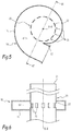
- the portion 22 of the conduit 20 is provided with through openings 23 which are visible on the Figures 5 and 6 .
- Each of these openings 23 connects the inner and outer faces of the portion 22 of the conduit 20 to one another.
- the openings 23 are distributed, preferably uniformly, all around the part 22. According to an advantageous characteristic of the invention, between six and twenty-four, preferably between eight and twelve, openings 23 are provided.
- each of the openings 23 has a rectangular passage section.
- other geometric shapes are possible for the passage sections of the openings 23.
- the ratio between, on the one hand, the total sum of the sections respective passage openings 23 and, secondly, the passage section of the portion 22 of the conduit 20, in other words the circular internal section of this portion 22 worth ⁇ times the square of its internal radius, is between 0, 05 and 0.4.
- the device 10 comprises a sheath 11 which, as is clearly visible on the Figures 4 to 6 , is designed to completely surround the portion 22 of the conduit 20.
- the internal volume V11 of the sheath 11 is thus wound externally around the portion 22 of the conduit 20, covering all the openings 23.
- This sheath 11 is provided with a mouth 12 input into its internal volume V11, as clearly visible on the figures 4 and 5 according to an advantageous characteristic of the invention, the passage section of this inlet mouth 12 is between 0.05 and 0.4 times the passage section of the portion 22 of the conduit 20.
- the internal volume V11 of the sheath 11 forms a spiral wound around the portion 22 of the duct 20, the internal volume V11 narrowing gradually to as one moves away from his entry mouth 12, as clearly visible on the figure 5 .
- the internal volume V11 preferably winds in a spiral or snail around the portion 22 of the conduit 20, its section being reduced as the winding of the sheath 11 around the conduit 20 from its mouth.
- the internal volume V11 of the sheath 11 may, as a variant, not shown, be annular, with a substantially constant section around the duct 20.
- the device 10 and / or the conduit 20 are made mainly, or even entirely, of a resin that withstands a temperature of at most 250 ° C.
- the device 10 and the conduit 20 may form an integral assembly in one piece or the device 10 may be attached to a pre-existing chimney which then constitutes the conduit 20 as long as the openings 23 can be made in a part circular profile of this chimney, at the axial level of which the device 10 will be arranged.
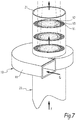
- F discharges typically combustion fumes loaded with moisture and having for example a temperature between 20 ° C and 65 ° C, flow vertically and upwardly in the conduit 20, from its inlet mouth to its mouth 21, as indicated by the arrows associated with the reference F on the figures 7 and 8 .
- a gas G feeds the inlet mouth 12 of the sheath 11.
- This gas G is hot, in the sense that it has a temperature strictly greater than that of the fumes F, the temperature difference between the gas G and the fumes F being several tens of degrees, for example between 45 ° C and 125 ° C.
- this hot gas G feeds the sheath 11 via ad hoc supply means, especially designed to send to the inlet mouth 12 of the heated air at a temperature between 80 ° C and 250 ° C, preferably between 100 ° C and 150 ° C.
- the hot gas G is channeled by the sheath 11 so as to turn around the portion 22 of the conduit 20. It is understood that the hot gas G flowing in the device 10 has a rotary movement relative to flue F circulating in the conduit 20, this rotating movement being oriented in a single direction of rotation about the axis XX.
- the hot gas G enters the conduit 20 with a component tangential to the axis XX and, inside the conduit 20, the hot gas G thus forms, mixing only marginally or almost is zero with the fumes F, a peripheral gas stream V1 constituting an annular sheath which is centered on the axis XX and which covers the inner face of the conduit 20 downstream of the portion 22, as shown in FIGS. figures 7 and 8 .
- the spiral shape advantageously allows a substantially constant speed to be maintained in the internal volume V11 of the sheath 11 as the hot gas G escapes inside the duct 20 through the openings 23.
- the flue gas F from the upstream side of the part 22 is, at the level of the part 22 and then downstream of the latter, forced towards the middle of the duct 20, forming a central gas stream V2 in which the mixture with the hot gas G is only marginal or even substantially non-existent.
- an intermediate gas stream V3 is formed radially between the peripheral vein V1 and the central stream V2, by substantial mixing between the fumes F and the hot gas G. Because of their respective compositions in fumes F and hot gas G, the veins V1, V2 and V3 have different respective temperatures: the peripheral vein V1 is much hotter than the central vein V2, the vein V3 having, for its part, a temperature gradient between the high temperature of the vein V1 and the low temperature vein V2.
- an inhomogeneous temperature profile is naturally established in the duct 20.
- the part of the gas stream located near the inner face of the duct 20 is hotter than the part of the duct. flow, located in the center of the duct.
- This inhomogeneous temperature profile is maintained from the portion 22 of the conduit 20 to its outlet mouth 21 and, by conservation of the momentum, the thermal shielding of the central vein V2 through the peripheral vein V1 is extended to the outside the conduit 20, beyond the outlet mouth 21, delaying or even avoiding the appearance of a plume.
- veins V1, V2 and V3 are schematized by different gray levels, being separated by dashed lines: this illustration is of course symbolic in the sense that, in practice, the veins V1, V2 and V3 are not materially separated from each other.
- this illustration makes it possible to clearly understand the stratification of the gaseous flow in the conduit 20 downstream of the device 10, being noted that, as clearly visible on the figure 7 this stratification results, in section planes perpendicular to the axis XX, by concentric circular profiles at the interface between the veins V1 and V3 and at the interface between the veins V3 and V2.
- an additional advantage provided by the invention is that the hot gas G distributed by the sheath 11 contributes to increasing the ejection speed at the outlet of the conduit 20, thus facilitating the dispersion of the fumes.
- the effective passage section that can occupy the fumes F downstream of the portion 22 is decreased compared to the upstream of this part 22: as the fumes F no longer occupy, alone, the entire passage section of the conduit 20, they acquire a higher speed and, after being out of the conduit 20, disperse more easily.
- the device 10 and the conduit 20 are used to limit the plume of fumes emitted by the propulsion diesel engine of a ship.
- the fumes to reject F have a flow rate of 125,000 Nm 3 / h and a temperature of 20 to 50 ° C, being saturated with moisture at this temperature.
- the hot gas G is air having a flow rate of 20,000 Nm 3 / h and a temperature of between 100 and 120 ° C.
- the conduit 20 is made of a temperature-resistant resin and has an internal diameter of 1800 mm. Its passage section is thus 2.54 m 2 .
- the sheath 11 is made of a resin resistant to temperature. This sheath has a spiral shape, as on the figure 5 .
- the passage section of its inlet mouth 12 is 0.78 m 2 .
- Eleven rectangular openings 23, 125 mm by 300 mm each, are provided in the portion 22 of the conduit 20.
- the cumulative total of the respective passage sections of these openings 23 is equal to 0.41 m 2 .
Landscapes
- Engineering & Computer Science (AREA)
- Mechanical Engineering (AREA)
- General Engineering & Computer Science (AREA)
- Chemical & Material Sciences (AREA)
- Combustion & Propulsion (AREA)
- Exhaust Silencers (AREA)
- Drying Of Solid Materials (AREA)
- Treating Waste Gases (AREA)
Applications Claiming Priority (1)
| Application Number | Priority Date | Filing Date | Title |
|---|---|---|---|
| FR1559109A FR3041689B1 (fr) | 2015-09-28 | 2015-09-28 | Dispositif de suppression, partielle voire totale, d'un panache de fumees, ainsi qu'installation de rejet de fumees a l'atmosphere comprenant un tel dispositif |
Publications (2)
| Publication Number | Publication Date |
|---|---|
| EP3147565A1 EP3147565A1 (fr) | 2017-03-29 |
| EP3147565B1 true EP3147565B1 (fr) | 2019-06-26 |
Family
ID=54545338
Family Applications (1)
| Application Number | Title | Priority Date | Filing Date |
|---|---|---|---|
| EP16191011.2A Active EP3147565B1 (fr) | 2015-09-28 | 2016-09-28 | Dispositif de suppression d'un panache de fumées, installation de rejet de fumées à l'atmosphère comprenant un tel dispositif, et navire marin correspondant |
Country Status (4)
| Country | Link |
|---|---|
| EP (1) | EP3147565B1 (da) |
| DK (1) | DK3147565T3 (da) |
| ES (1) | ES2737750T3 (da) |
| FR (1) | FR3041689B1 (da) |
Families Citing this family (2)
| Publication number | Priority date | Publication date | Assignee | Title |
|---|---|---|---|---|
| CN109340806A (zh) * | 2018-06-26 | 2019-02-15 | 刘家良 | 一种直混烟气加热装置 |
| CN114682059B (zh) * | 2020-12-30 | 2023-07-04 | 中国石油化工股份有限公司 | 枝杈式消白烟设备及消白烟方法 |
Family Cites Families (8)
| Publication number | Priority date | Publication date | Assignee | Title |
|---|---|---|---|---|
| US3566768A (en) * | 1969-01-22 | 1971-03-02 | Air Preheater | Stack-jet curtain |
| DE2123220A1 (de) * | 1971-05-11 | 1972-11-23 | Brandi Ingenieurgesellschaft mbH, 5020 Frechen | Verfahren und Vorrichtung zum Betrieb eines Rückkühlwerkes bzw. Kühlturmes |
| DE2238790C2 (de) * | 1972-08-07 | 1974-07-04 | Apparatebau Rothemuehle Brandt & Kritzler, 5963 Wenden | Abgasreinigungsanlage |
| US4149453A (en) * | 1977-04-19 | 1979-04-17 | John Zink Company | No-plume device |
| FR2482261B1 (fr) * | 1980-05-09 | 1985-07-26 | Lab | Perfectionnements aux cheminees industrielles vicard |
| FI125076B (fi) * | 2008-04-09 | 2015-05-29 | Wärtsilä Finland Oy | Koneistojärjestely vesikulkuneuvoon ja menetelmä vesikulkuneuvon koneistojärjestelyn käyttämiseksi |
| US8721771B2 (en) | 2011-01-21 | 2014-05-13 | Heartland Technology Partners Llc | Condensation plume mitigation system for exhaust stacks |
| EP2609995A1 (en) * | 2011-12-29 | 2013-07-03 | Brunnschweiler S.A. | Method and system for reducing the plume created at the outlet of an industrial process |
-
2015
- 2015-09-28 FR FR1559109A patent/FR3041689B1/fr active Active
-
2016
- 2016-09-28 DK DK16191011.2T patent/DK3147565T3/da active
- 2016-09-28 EP EP16191011.2A patent/EP3147565B1/fr active Active
- 2016-09-28 ES ES16191011T patent/ES2737750T3/es active Active
Non-Patent Citations (1)
| Title |
|---|
| None * |
Also Published As
| Publication number | Publication date |
|---|---|
| DK3147565T3 (da) | 2019-07-22 |
| FR3041689A1 (fr) | 2017-03-31 |
| EP3147565A1 (fr) | 2017-03-29 |
| ES2737750T3 (es) | 2020-01-15 |
| FR3041689B1 (fr) | 2019-06-28 |
Similar Documents
| Publication | Publication Date | Title |
|---|---|---|
| FR2614072A1 (fr) | Moteur-turbopropulseur a turbine a gaz | |
| EP0200644A1 (fr) | Procédé pour la combustion de combustibles fluides et brûleur à turbulence adapté à sa mise en oeuvre | |
| EP0911585A1 (fr) | Accroche-flamme carburé et refroidi | |
| FR2585770A1 (fr) | Dispositif d'injection a bol elargi pour chambre de combustion de turbomachine | |
| CA2925565C (fr) | Chambre de combustion de turbomachine pourvue de moyens de deflection d'air pour reduire le sillage cree par une bougie d'allumage | |
| EP3569929A1 (fr) | Ensemble pour une chambre de combustion de turbomachine | |
| EP3147565B1 (fr) | Dispositif de suppression d'un panache de fumées, installation de rejet de fumées à l'atmosphère comprenant un tel dispositif, et navire marin correspondant | |
| EP0099828A2 (fr) | Dispositif pour la combustion de fluides combustibles avec induction d'air | |
| EP0964206B1 (fr) | Chambre de combustion de turbine à gaz à géométrie variable | |
| WO2017198653A1 (fr) | Dispositif d'introduction de fumées d'échappement d'un moteur de navire marin dans un laveur | |
| EP0686686B1 (fr) | Four de traitement thermique de déchets et procédé associé | |
| EP0879995B1 (fr) | Système de réchauffe dichotomique réduisant les pertes en sec. | |
| EP0967434B1 (fr) | Brûleur à conduits concentriques d'alimentation en air et à stabilisateur central | |
| EP2076659B1 (fr) | Ligne d'echappement munie d'un injecteur de carburant et de moyens d'homogeneisation des gaz brules | |
| EP2071240B1 (fr) | Chambre de combustion de turbomachine | |
| FR2930972A1 (fr) | Turbomachine a double flux pour aeronef a emission de bruit reduite | |
| CA2498242A1 (fr) | Procede d'amelioration des performances d'allumage de dispositif de post-combustion pour turboreacteur double flux et dispositif de post-combustion a performance d'allumage amelioree | |
| WO2005039367A1 (fr) | Procede d’allumage d’un appareil a combustible solide, et appareil permettant de mettre en oeuvre le procede | |
| WO2024209157A1 (fr) | Conduit d'échappement d'un banc d'essai de turbine avec double tube | |
| EP0094890A1 (fr) | Chaudière à combustible solide du type à tube foyer rayonnant, procédé de transformation d'une chaudière et moyens pour sa mise en oeuvre | |
| EP2283278B1 (fr) | Brûleur à points périphériques d'injection d'air à flux axial | |
| FR2937120A1 (fr) | Dispositif de dispersion de gaz sortant d'une cheminee | |
| FR2761458A1 (fr) | Incinerateur de dechets liquides, pateux et solides | |
| FR2982011A1 (fr) | Dispositif de recuperation de chaleur pour un poele, notamment un poele a bois, ainsi qu'installation correspondante de chauffage d'un batiment | |
| FR3086188A1 (fr) | Dispositif de protection de l'admission de fumees dans un laveur, ainsi qu'installation d'epuration comportant un tel dispositif de protection |
Legal Events
| Date | Code | Title | Description |
|---|---|---|---|
| PUAI | Public reference made under article 153(3) epc to a published international application that has entered the european phase |
Free format text: ORIGINAL CODE: 0009012 |
|
| STAA | Information on the status of an ep patent application or granted ep patent |
Free format text: STATUS: THE APPLICATION HAS BEEN PUBLISHED |
|
| AK | Designated contracting states |
Kind code of ref document: A1 Designated state(s): AL AT BE BG CH CY CZ DE DK EE ES FI FR GB GR HR HU IE IS IT LI LT LU LV MC MK MT NL NO PL PT RO RS SE SI SK SM TR |
|
| AX | Request for extension of the european patent |
Extension state: BA ME |
|
| STAA | Information on the status of an ep patent application or granted ep patent |
Free format text: STATUS: REQUEST FOR EXAMINATION WAS MADE |
|
| 17P | Request for examination filed |
Effective date: 20170913 |
|
| RBV | Designated contracting states (corrected) |
Designated state(s): AL AT BE BG CH CY CZ DE DK EE ES FI FR GB GR HR HU IE IS IT LI LT LU LV MC MK MT NL NO PL PT RO RS SE SI SK SM TR |
|
| GRAP | Despatch of communication of intention to grant a patent |
Free format text: ORIGINAL CODE: EPIDOSNIGR1 |
|
| STAA | Information on the status of an ep patent application or granted ep patent |
Free format text: STATUS: GRANT OF PATENT IS INTENDED |
|
| INTG | Intention to grant announced |
Effective date: 20190201 |
|
| GRAS | Grant fee paid |
Free format text: ORIGINAL CODE: EPIDOSNIGR3 |
|
| GRAA | (expected) grant |
Free format text: ORIGINAL CODE: 0009210 |
|
| STAA | Information on the status of an ep patent application or granted ep patent |
Free format text: STATUS: THE PATENT HAS BEEN GRANTED |
|
| AK | Designated contracting states |
Kind code of ref document: B1 Designated state(s): AL AT BE BG CH CY CZ DE DK EE ES FI FR GB GR HR HU IE IS IT LI LT LU LV MC MK MT NL NO PL PT RO RS SE SI SK SM TR |
|
| REG | Reference to a national code |
Ref country code: GB Ref legal event code: FG4D Free format text: NOT ENGLISH |
|
| REG | Reference to a national code |
Ref country code: CH Ref legal event code: EP |
|
| REG | Reference to a national code |
Ref country code: DE Ref legal event code: R096 Ref document number: 602016015827 Country of ref document: DE |
|
| REG | Reference to a national code |
Ref country code: AT Ref legal event code: REF Ref document number: 1148726 Country of ref document: AT Kind code of ref document: T Effective date: 20190715 |
|
| REG | Reference to a national code |
Ref country code: DK Ref legal event code: T3 Effective date: 20190717 |
|
| REG | Reference to a national code |
Ref country code: IE Ref legal event code: FG4D Free format text: LANGUAGE OF EP DOCUMENT: FRENCH |
|
| REG | Reference to a national code |
Ref country code: NL Ref legal event code: FP |
|
| PG25 | Lapsed in a contracting state [announced via postgrant information from national office to epo] |
Ref country code: HR Free format text: LAPSE BECAUSE OF FAILURE TO SUBMIT A TRANSLATION OF THE DESCRIPTION OR TO PAY THE FEE WITHIN THE PRESCRIBED TIME-LIMIT Effective date: 20190626 Ref country code: AL Free format text: LAPSE BECAUSE OF FAILURE TO SUBMIT A TRANSLATION OF THE DESCRIPTION OR TO PAY THE FEE WITHIN THE PRESCRIBED TIME-LIMIT Effective date: 20190626 Ref country code: FI Free format text: LAPSE BECAUSE OF FAILURE TO SUBMIT A TRANSLATION OF THE DESCRIPTION OR TO PAY THE FEE WITHIN THE PRESCRIBED TIME-LIMIT Effective date: 20190626 Ref country code: LT Free format text: LAPSE BECAUSE OF FAILURE TO SUBMIT A TRANSLATION OF THE DESCRIPTION OR TO PAY THE FEE WITHIN THE PRESCRIBED TIME-LIMIT Effective date: 20190626 Ref country code: SE Free format text: LAPSE BECAUSE OF FAILURE TO SUBMIT A TRANSLATION OF THE DESCRIPTION OR TO PAY THE FEE WITHIN THE PRESCRIBED TIME-LIMIT Effective date: 20190626 |
|
| REG | Reference to a national code |
Ref country code: NO Ref legal event code: T2 Effective date: 20190626 Ref country code: LT Ref legal event code: MG4D |
|
| PG25 | Lapsed in a contracting state [announced via postgrant information from national office to epo] |
Ref country code: RS Free format text: LAPSE BECAUSE OF FAILURE TO SUBMIT A TRANSLATION OF THE DESCRIPTION OR TO PAY THE FEE WITHIN THE PRESCRIBED TIME-LIMIT Effective date: 20190626 Ref country code: BG Free format text: LAPSE BECAUSE OF FAILURE TO SUBMIT A TRANSLATION OF THE DESCRIPTION OR TO PAY THE FEE WITHIN THE PRESCRIBED TIME-LIMIT Effective date: 20190926 Ref country code: LV Free format text: LAPSE BECAUSE OF FAILURE TO SUBMIT A TRANSLATION OF THE DESCRIPTION OR TO PAY THE FEE WITHIN THE PRESCRIBED TIME-LIMIT Effective date: 20190626 Ref country code: GR Free format text: LAPSE BECAUSE OF FAILURE TO SUBMIT A TRANSLATION OF THE DESCRIPTION OR TO PAY THE FEE WITHIN THE PRESCRIBED TIME-LIMIT Effective date: 20190927 |
|
| REG | Reference to a national code |
Ref country code: AT Ref legal event code: MK05 Ref document number: 1148726 Country of ref document: AT Kind code of ref document: T Effective date: 20190626 Ref country code: ES Ref legal event code: FG2A Ref document number: 2737750 Country of ref document: ES Kind code of ref document: T3 Effective date: 20200115 |
|
| PG25 | Lapsed in a contracting state [announced via postgrant information from national office to epo] |
Ref country code: SK Free format text: LAPSE BECAUSE OF FAILURE TO SUBMIT A TRANSLATION OF THE DESCRIPTION OR TO PAY THE FEE WITHIN THE PRESCRIBED TIME-LIMIT Effective date: 20190626 Ref country code: RO Free format text: LAPSE BECAUSE OF FAILURE TO SUBMIT A TRANSLATION OF THE DESCRIPTION OR TO PAY THE FEE WITHIN THE PRESCRIBED TIME-LIMIT Effective date: 20190626 Ref country code: CZ Free format text: LAPSE BECAUSE OF FAILURE TO SUBMIT A TRANSLATION OF THE DESCRIPTION OR TO PAY THE FEE WITHIN THE PRESCRIBED TIME-LIMIT Effective date: 20190626 Ref country code: PT Free format text: LAPSE BECAUSE OF FAILURE TO SUBMIT A TRANSLATION OF THE DESCRIPTION OR TO PAY THE FEE WITHIN THE PRESCRIBED TIME-LIMIT Effective date: 20191028 Ref country code: EE Free format text: LAPSE BECAUSE OF FAILURE TO SUBMIT A TRANSLATION OF THE DESCRIPTION OR TO PAY THE FEE WITHIN THE PRESCRIBED TIME-LIMIT Effective date: 20190626 Ref country code: AT Free format text: LAPSE BECAUSE OF FAILURE TO SUBMIT A TRANSLATION OF THE DESCRIPTION OR TO PAY THE FEE WITHIN THE PRESCRIBED TIME-LIMIT Effective date: 20190626 |
|
| PG25 | Lapsed in a contracting state [announced via postgrant information from national office to epo] |
Ref country code: IS Free format text: LAPSE BECAUSE OF FAILURE TO SUBMIT A TRANSLATION OF THE DESCRIPTION OR TO PAY THE FEE WITHIN THE PRESCRIBED TIME-LIMIT Effective date: 20191026 Ref country code: SM Free format text: LAPSE BECAUSE OF FAILURE TO SUBMIT A TRANSLATION OF THE DESCRIPTION OR TO PAY THE FEE WITHIN THE PRESCRIBED TIME-LIMIT Effective date: 20190626 |
|
| PG25 | Lapsed in a contracting state [announced via postgrant information from national office to epo] |
Ref country code: TR Free format text: LAPSE BECAUSE OF FAILURE TO SUBMIT A TRANSLATION OF THE DESCRIPTION OR TO PAY THE FEE WITHIN THE PRESCRIBED TIME-LIMIT Effective date: 20190626 |
|
| PG25 | Lapsed in a contracting state [announced via postgrant information from national office to epo] |
Ref country code: PL Free format text: LAPSE BECAUSE OF FAILURE TO SUBMIT A TRANSLATION OF THE DESCRIPTION OR TO PAY THE FEE WITHIN THE PRESCRIBED TIME-LIMIT Effective date: 20190626 |
|
| PG25 | Lapsed in a contracting state [announced via postgrant information from national office to epo] |
Ref country code: MC Free format text: LAPSE BECAUSE OF FAILURE TO SUBMIT A TRANSLATION OF THE DESCRIPTION OR TO PAY THE FEE WITHIN THE PRESCRIBED TIME-LIMIT Effective date: 20190626 Ref country code: IS Free format text: LAPSE BECAUSE OF FAILURE TO SUBMIT A TRANSLATION OF THE DESCRIPTION OR TO PAY THE FEE WITHIN THE PRESCRIBED TIME-LIMIT Effective date: 20200224 |
|
| REG | Reference to a national code |
Ref country code: CH Ref legal event code: PL |
|
| REG | Reference to a national code |
Ref country code: DE Ref legal event code: R097 Ref document number: 602016015827 Country of ref document: DE |
|
| PLBE | No opposition filed within time limit |
Free format text: ORIGINAL CODE: 0009261 |
|
| STAA | Information on the status of an ep patent application or granted ep patent |
Free format text: STATUS: NO OPPOSITION FILED WITHIN TIME LIMIT |
|
| PG2D | Information on lapse in contracting state deleted |
Ref country code: IS |
|
| PG25 | Lapsed in a contracting state [announced via postgrant information from national office to epo] |
Ref country code: LU Free format text: LAPSE BECAUSE OF NON-PAYMENT OF DUE FEES Effective date: 20190928 Ref country code: IE Free format text: LAPSE BECAUSE OF NON-PAYMENT OF DUE FEES Effective date: 20190928 Ref country code: LI Free format text: LAPSE BECAUSE OF NON-PAYMENT OF DUE FEES Effective date: 20190930 Ref country code: CH Free format text: LAPSE BECAUSE OF NON-PAYMENT OF DUE FEES Effective date: 20190930 |
|
| 26N | No opposition filed |
Effective date: 20200603 |
|
| REG | Reference to a national code |
Ref country code: BE Ref legal event code: MM Effective date: 20190930 |
|
| PG25 | Lapsed in a contracting state [announced via postgrant information from national office to epo] |
Ref country code: SI Free format text: LAPSE BECAUSE OF FAILURE TO SUBMIT A TRANSLATION OF THE DESCRIPTION OR TO PAY THE FEE WITHIN THE PRESCRIBED TIME-LIMIT Effective date: 20190626 Ref country code: BE Free format text: LAPSE BECAUSE OF NON-PAYMENT OF DUE FEES Effective date: 20190930 |
|
| PG25 | Lapsed in a contracting state [announced via postgrant information from national office to epo] |
Ref country code: CY Free format text: LAPSE BECAUSE OF FAILURE TO SUBMIT A TRANSLATION OF THE DESCRIPTION OR TO PAY THE FEE WITHIN THE PRESCRIBED TIME-LIMIT Effective date: 20190626 |
|
| PG25 | Lapsed in a contracting state [announced via postgrant information from national office to epo] |
Ref country code: HU Free format text: LAPSE BECAUSE OF FAILURE TO SUBMIT A TRANSLATION OF THE DESCRIPTION OR TO PAY THE FEE WITHIN THE PRESCRIBED TIME-LIMIT; INVALID AB INITIO Effective date: 20160928 Ref country code: MT Free format text: LAPSE BECAUSE OF FAILURE TO SUBMIT A TRANSLATION OF THE DESCRIPTION OR TO PAY THE FEE WITHIN THE PRESCRIBED TIME-LIMIT Effective date: 20190626 |
|
| PG25 | Lapsed in a contracting state [announced via postgrant information from national office to epo] |
Ref country code: MK Free format text: LAPSE BECAUSE OF FAILURE TO SUBMIT A TRANSLATION OF THE DESCRIPTION OR TO PAY THE FEE WITHIN THE PRESCRIBED TIME-LIMIT Effective date: 20190626 |
|
| P01 | Opt-out of the competence of the unified patent court (upc) registered |
Effective date: 20230516 |
|
| PGFP | Annual fee paid to national office [announced via postgrant information from national office to epo] |
Ref country code: NL Payment date: 20230824 Year of fee payment: 8 |
|
| PGFP | Annual fee paid to national office [announced via postgrant information from national office to epo] |
Ref country code: NO Payment date: 20230822 Year of fee payment: 8 Ref country code: IT Payment date: 20230911 Year of fee payment: 8 Ref country code: GB Payment date: 20230920 Year of fee payment: 8 |
|
| PGFP | Annual fee paid to national office [announced via postgrant information from national office to epo] |
Ref country code: DK Payment date: 20230824 Year of fee payment: 8 Ref country code: DE Payment date: 20230911 Year of fee payment: 8 |
|
| PGFP | Annual fee paid to national office [announced via postgrant information from national office to epo] |
Ref country code: ES Payment date: 20231006 Year of fee payment: 8 |
|
| REG | Reference to a national code |
Ref country code: DE Ref legal event code: R119 Ref document number: 602016015827 Country of ref document: DE |
|
| REG | Reference to a national code |
Ref country code: DK Ref legal event code: EBP Effective date: 20240930 |
|
| REG | Reference to a national code |
Ref country code: NL Ref legal event code: MM Effective date: 20241001 |
|
| GBPC | Gb: european patent ceased through non-payment of renewal fee |
Effective date: 20240928 |
|
| PG25 | Lapsed in a contracting state [announced via postgrant information from national office to epo] |
Ref country code: NL Free format text: LAPSE BECAUSE OF NON-PAYMENT OF DUE FEES Effective date: 20241001 |
|
| PG25 | Lapsed in a contracting state [announced via postgrant information from national office to epo] |
Ref country code: DE Free format text: LAPSE BECAUSE OF NON-PAYMENT OF DUE FEES Effective date: 20250401 |
|
| PG25 | Lapsed in a contracting state [announced via postgrant information from national office to epo] |
Ref country code: GB Free format text: LAPSE BECAUSE OF NON-PAYMENT OF DUE FEES Effective date: 20240928 |
|
| PG25 | Lapsed in a contracting state [announced via postgrant information from national office to epo] |
Ref country code: NO Free format text: LAPSE BECAUSE OF NON-PAYMENT OF DUE FEES Effective date: 20240930 |
|
| PG25 | Lapsed in a contracting state [announced via postgrant information from national office to epo] |
Ref country code: IT Free format text: LAPSE BECAUSE OF NON-PAYMENT OF DUE FEES Effective date: 20240928 |
|
| PG25 | Lapsed in a contracting state [announced via postgrant information from national office to epo] |
Ref country code: DK Free format text: LAPSE BECAUSE OF NON-PAYMENT OF DUE FEES Effective date: 20240930 |
|
| PGFP | Annual fee paid to national office [announced via postgrant information from national office to epo] |
Ref country code: FR Payment date: 20250812 Year of fee payment: 10 |
|
| REG | Reference to a national code |
Ref country code: ES Ref legal event code: FD2A Effective date: 20251103 |
|
| PG25 | Lapsed in a contracting state [announced via postgrant information from national office to epo] |
Ref country code: ES Free format text: LAPSE BECAUSE OF NON-PAYMENT OF DUE FEES Effective date: 20240929 |