EP3147566A1 - Système de brûleur à gaz pour une cuisinière à gaz avec un thermocouple - Google Patents
Système de brûleur à gaz pour une cuisinière à gaz avec un thermocouple Download PDFInfo
- Publication number
- EP3147566A1 EP3147566A1 EP15186148.1A EP15186148A EP3147566A1 EP 3147566 A1 EP3147566 A1 EP 3147566A1 EP 15186148 A EP15186148 A EP 15186148A EP 3147566 A1 EP3147566 A1 EP 3147566A1
- Authority
- EP
- European Patent Office
- Prior art keywords
- gas
- thermocouple
- gas burner
- signal
- fuel
- Prior art date
- Legal status (The legal status is an assumption and is not a legal conclusion. Google has not performed a legal analysis and makes no representation as to the accuracy of the status listed.)
- Granted
Links
Images

Classifications
-
- F—MECHANICAL ENGINEERING; LIGHTING; HEATING; WEAPONS; BLASTING
- F24—HEATING; RANGES; VENTILATING
- F24C—DOMESTIC STOVES OR RANGES ; DETAILS OF DOMESTIC STOVES OR RANGES, OF GENERAL APPLICATION
- F24C3/00—Stoves or ranges for gaseous fuels
- F24C3/12—Arrangement or mounting of control or safety devices
- F24C3/126—Arrangement or mounting of control or safety devices on ranges
-
- F—MECHANICAL ENGINEERING; LIGHTING; HEATING; WEAPONS; BLASTING
- F23—COMBUSTION APPARATUS; COMBUSTION PROCESSES
- F23D—BURNERS
- F23D14/00—Burners for combustion of a gas, e.g. of a gas stored under pressure as a liquid
- F23D14/02—Premix gas burners, i.e. in which gaseous fuel is mixed with combustion air upstream of the combustion zone
- F23D14/04—Premix gas burners, i.e. in which gaseous fuel is mixed with combustion air upstream of the combustion zone induction type, e.g. Bunsen burner
-
- F—MECHANICAL ENGINEERING; LIGHTING; HEATING; WEAPONS; BLASTING
- F23—COMBUSTION APPARATUS; COMBUSTION PROCESSES
- F23N—REGULATING OR CONTROLLING COMBUSTION
- F23N1/00—Regulating fuel supply
- F23N1/02—Regulating fuel supply conjointly with air supply
- F23N1/022—Regulating fuel supply conjointly with air supply using electronic means
-
- F—MECHANICAL ENGINEERING; LIGHTING; HEATING; WEAPONS; BLASTING
- F23—COMBUSTION APPARATUS; COMBUSTION PROCESSES
- F23N—REGULATING OR CONTROLLING COMBUSTION
- F23N3/00—Regulating air supply or draught
- F23N3/04—Regulating air supply or draught by operation of single valves or dampers by temperature sensitive elements
- F23N3/042—Regulating air supply or draught by operation of single valves or dampers by temperature sensitive elements using electronic means
-
- F—MECHANICAL ENGINEERING; LIGHTING; HEATING; WEAPONS; BLASTING
- F23—COMBUSTION APPARATUS; COMBUSTION PROCESSES
- F23N—REGULATING OR CONTROLLING COMBUSTION
- F23N5/00—Systems for controlling combustion
- F23N5/02—Systems for controlling combustion using devices responsive to thermal changes or to thermal expansion of a medium
- F23N5/10—Systems for controlling combustion using devices responsive to thermal changes or to thermal expansion of a medium using thermocouples
- F23N5/102—Systems for controlling combustion using devices responsive to thermal changes or to thermal expansion of a medium using thermocouples using electronic means
-
- F—MECHANICAL ENGINEERING; LIGHTING; HEATING; WEAPONS; BLASTING
- F23—COMBUSTION APPARATUS; COMBUSTION PROCESSES
- F23N—REGULATING OR CONTROLLING COMBUSTION
- F23N2241/00—Applications
- F23N2241/08—Household apparatus
Definitions
- the present invention relates to a gas burner arrangement for a gas-cooking appliance, a gas-cooking appliance comprising such gas burner arrangement and a method for determining if a cooking vessel is placed above a gas burner.
- a gas-cooking appliance particularly a gas hob, as known in the art usually comprises a gas burner arrangement with at least one gas burner adapted to receive a fuel flow, particularly a flow of gas or a gas-air mixture, from a fuel supply.
- the fuel is used to provide a fuel-supplied flame to a cooking vessel placed above said flame above the gas burner.
- gas-cooking appliance further comprises at least one support arranged to support the cooking vessel above the flame or burner.
- thermocouple for example gas hobs
- thermocouple usually is adapted to generate a thermocouple signal depending on the thermal state of said thermocouple.
- the thermocouple usually is connected to a control unit being adapted to receive the thermocouple signal.
- thermocouple is used for safety reasons to detect whether a flame is on. When the flame is on the TC is generating a tension at its end, and then this tension is usually fed to a mechanical tap in order to allow the gas to feed the burner.
- the document GB 2 146 804 A describes a temperature control arrangement for controlling the temperature of a gas burner in accordance with a desired operating temperature set by a user-operable control knob.
- a temperature sensing circuit includes a TC, which monitors the temperature of a cooking vessel being heated.
- a comparator compares two input signals, indicative respectively of the temperature sensed by the TC and of the temperature set on the potentiometer, and generates an error signal. Accordingly, a solenoid gas valve is activated in dependence on the error signal.
- safety and combustion in such configuration are insufficiently controlled.
- the document WO 02 097 333 A2 describes a gas cooker having a TC in order to avoid an additional temperature sensor.
- the TC is connected to a heat display unit, which displays a heat status for the gas cooker point, depending on a parameter from the TC signal.
- safety and combustion in such configuration are insufficiently controlled.
- US2010239987A describes a method for operating a cooking point with a gas burner of a gas hob disclosed in which pan detection is provided for switching off the gas burner when the pan is removed.
- said document mainly focusses on a method to switch off or not gas and does not disclose a possibility to sense, if the pot is placed on the pan support or not.
- a gas burner arrangement according to claim 1 a gas-cooking appliance comprising such gas burner arrangement according to claim 13, and a method for determining if a cooking vessel is placed above a gas burner of a gas burner arrangement according to claim 14.
- a gas burner arrangement for a gas-cooking appliance, particularly a gas hob, according to claim 1 comprises at least one gas burner adapted to receive a fuel flow from a fuel supply and for providing a fuel-supplied flame to a cooking vessel. Thereby, the cooking vessel can be placed above the gas burner, particularly above the fuel-supplied flame.
- Such gas burner arrangement according to the present invention further comprises at least one support arranged to support the cooking vessel above the gas burner, particularly above the fuel-supplied flame, and a thermocouple adapted to generate a thermocouple signal depending on the thermal state of said thermocouple.
- a gas burner arrangement comprises a control unit connected to the thermocouple, the control unit being adapted to receive the thermocouple signal and to process said thermocouple signal to an output signal.
- the control unit is capable of determining if the cooking vessel is placed on the support, particularly above the fuel-supplied flame, dependent on the thermocouple signal.
- thermocouple signal particularly in the form of thermo-tension of such thermocouple
- a generic cooking vessel for example a pot, pan, grid, or the like
- the level of the thermocouple signal changes significantly, if such vessel is placed over the flame, particularly over the support or burner, or not.
- a gas burner arrangement for a gas-cooking appliance comprises at least one gas burner adapted to receive a fuel flow from a fuel supply and for providing a fuel-supplied flame to a cooking vessel.
- fuel may be a gas or a gas-air mixture.
- a person skilled in the art will immediately acknowledge that usually such fuel-supplied flame is supplied with a gas or a gas-air mixture, particularly a gas-air mixture, and usually uses a primary air supply in form of the air, which is fed to the burner from below the cooktop and/or the burner. Thereby, usually the amount of the primary air in the air-gas mixture ranges from about 60% to about 80%, whereby stoichiometric would be 100%.
- thermocouple In a state where the flame or burner supplied by said fuel is burning, the thermocouple generates a thermocouple signal depending on the thermal state of said thermocouple.
- a thermocouple of various types can be applied.
- a standard thermocouple as used for safety reasons in known gas hobs can be applied.
- thermocouple as used herein, preferably refers to a temperature-measuring device comprising two dissimilar conductors or semiconductors that contact each other at one or more spots, where a temperature differential is experienced by the different conductors or semiconductors. Upon such temperature differential, the thermocouple produces a voltage or tension when the temperature of one of the spots differs from the reference temperature at other parts of the circuit.
- a thermocouple as used herein may be adapted to convert a temperature gradient into an electrical current signal.
- a thermocouple is advantageous in that it is relatively inexpensive, interchangeable, may be supplied with standard connectors, and/or can measure a wide range of temperatures. In contrast to most other methods of temperature measurement, thermocouples are advantageous in that such thermocouple can be self-powered and require no external form of excitation.
- the thermocouple is connected to a control unit, which is adapted to receive the thermocouple signal, e.g. a thermo-tension or thermoelectric current as an input signal. Said input signal is processed into an output signal by the control unit.
- the control unit comprises a comparator and is adapted to generate an output signal dependent on the comparison of the thermocouple signal to at least one predetermined set value.
- Such predetermined set value may be stored in the control unit. Particularly, such predetermined set value can be a threshold value to which the thermocouple signal is compared.
- Such method according to the present invention comprises at least the following steps:
- features referring to a gas burner arrangement according to the method of the present invention may also be features of a gas burner arrangement according to the present invention.
- control unit is capable of determining if the cooking vessel is placed above the fuel-supplied flame dependent on the thermocouple signal, either by a significant change of the thermocouple signal characteristic for a state where a vessel is placed or not placed above the flame, burner or the support, or alternatively or additionally by comparison of the thermocouple signal to a predetermined set value.
- said method in step b) further comprises comparing the thermocouple signal to at least one first predetermined set value for at least one first predetermined amount of time.
- the control unit of the gas burner arrangement of the present invention is capable of comparing the thermocouple signal to at least one first predetermined set value for at least one first predetermined amount of time. If the thermocouple signal for the first predetermined amount of time is lower than the at least one first predetermined set value, said output signal generated by the control unit, particularly in step c) of the method according to the present invention, is indicative for a state in which a cooking vessel is placed on the support, particularly above the fuel-supplied flame.
- said method in step b) further comprises comparing the thermocouple signal to at least one second predetermined set value for at least one second predetermined amount of time.
- the control unit of the gas burner arrangement of the present invention is capable of comparing the thermocouple signal to at least one second predetermined set value for at least one second predetermined amount of time. If the thermocouple signal for the second predetermined amount of time is higher than the at least one second predetermined set value, said output signal generated by the control unit, particularly in step c) of the method according to the present invention, is indicative for a state in which no cooking vessel is placed on the support, particularly above the fuel-supplied flame.
- the at least one first predetermined set value and the at least one second predetermined set value are identical.
- the at least one first predetermined set value is different from the at least one second predetermined set value.
- the at least one first predetermined amount of time and the at least one second predetermined amount of time are identical.
- the at least one first predetermined amount of time is different from the at least one second predetermined amount of time, or at least partially overlap.
- a first predetermined set value is indicative for a state in which a cooking vessel is placed on the support, particularly above the fuel-supplied flame.
- the thermocouple signal may be compared to a second predetermined set value, i.e. the period for comparison to the first and the second predetermined set value is identical. Said second predetermined set value thereby is indicative for a state in which no cooking vessel is placed on the support, particularly above the fuel-supplied flame.
- thermocouple signal is compared to said first predetermined set value and to said second predetermined set value, and if the thermocouple signal is lower than the first predetermined set value, said output signal generated by the control unit is indicative that a cooking vessel is placed on the support, particularly above the fuel-supplied flame. However, if the thermocouple signal is higher than the second predetermined set value, said output signal generated by the control unit is indicative for a state in which no cooking vessel is placed on the support, particularly above the fuel-supplied flame.
- the distance between the cooking vessel, particularly the bottom of such cooking vessel, and the gas burner, particularly the fuel-supplied flame is about 3.0 cm, preferably of about 2.0 cm, more preferably of about 1.0 cm. It will be immediately understood by a person skilled in the art that the distance between cooking vessel and the gas burner, particularly the flame, can be adjusted dependent on the height of a support arranged to support the cooking vessel above the gas burner, particularly above the fuel-supplied flame.
- the support is arranged such that the cooking vessel is placed above the gas burner, particularly above the flame, with a distance to about 3 cm, preferably of about 2 cm, more preferably of about 1 cm.
- the distance between the cooking vessel, and the gas burner, particularly the flame is relatively low. This is, as the present inventors have found that, if the distance between the cooking vessel and the gas burner, particularly the flame, is shorter, the more indicative for the presence or non-presence of a vessel is the thermocouple signal, and particularly a change thereof. Particularly, in an embodiment according to which the thermocouple signal is compared to a first and to a second predetermined set value, the distance between said predetermined set values can be higher, if the distance between the cooking vessel and the gas burner, particularly the flame is lower.
- having a relatively low distance between the cooking vessel and the gas burner, particularly the flame allows for a relatively high difference between a first and a second predetermined set value. Accordingly, the accuracy of determination whether a cooking vessel is present or not can be higher, if the distance between cooking vessel and the gas burner, particularly the flame, is relatively low.
- thermocouple signal is a thermos-tension and/or a thermoelectric current.
- thermocouples generating a signal in the form of a thermo-tension and/or a thermoelectric current are of particular advantage, as such thermocouples can be arranged and exchanged relatively easy, and are of generally low costs.
- thermocouple is arranged such that the thermocouple signal is indicative for whether the cooking vessel is placed above the support, particularly above the fuel-supplied flame.
- thermocouple advantageously allows to determine dependent on the thermocouple signal, particularly the thermocouple signal being compared to at least one predetermined set value, whether a cooking vessel is placed above the support, particularly above the fuel-supplied flame, or not.
- thermocouple is arranged at a position, which is below a cooking vessel to be placed on the support.
- thermocouple below a cooking vessel to be placed on the support, advantageously allows to determine dependent on the thermocouple signal, particularly the thermocouple signal being compared to at least one predetermined set value, whether a cooking vessel is placed above the support, particularly above the fuel-supplied flame, or not.
- thermocouple is arranged adjacent to the gas burner, particularly adjacent to the fuel-supplied flame.
- thermocouple is advantageous, as the placement allows for a compact design of the gas burner arrangement according to the present invention. Moreover, the thermocouple being placed adjacent to the gas burner, particularly adjacent to the fuel-supplied flame, allows for a relatively precise determination of whether a cooking vessel is placed above the support, particularly above the fuel-supplied flame, or not.
- the gas burner of the gas burner arrangement and/or the method according to the present invention may in general be of usually applied gas burner types.
- the gas burner is a flush burner.
- a "flush burner” as used herein, preferably refers to a burner in which the flame spreader is flush to the cooktop.
- the flame shape is changing a lot with and without the cooking vessel. This will facilitate to determine whether a cooking vessel is or is not placed on the support, particularly above a flame. This is, as particularly a difference between a first and a second predetermined set value is bigger.
- the gas burner may be a cylindical gas burner, particularly with a 'tower' style.
- control unit is connected to at least one regulation means.
- regulation means is capable of regulating the fuel received by the at least one gas burner from the fuel supply, dependent on the output signal.
- the flow rate of the fuel may be regulated dependent on the output signal.
- the fuel flow rate may be turned on or off, dependent on whether a vessel is placed above the burner or flame, or not.
- the operation unit may be adapted to control the regulation means such that the fuel flow rate is lowered or turned off, dependent on the output signal, if no vessel is placed above the burner or flame.
- the operation unit may be adapted to control the regulation means such that the fuel flow rate is increased or turned on, dependent on the output signal, if a vessel is placed above the burner or flame.
- the at least one regulation means is a valve, preferably an electronic gas valve.
- a valve for control of gas flow and one valve for control of an air supply is provided.
- one valve for regulating the flow rate of a fuel mixture is provided.
- Such valve(s) advantageously allow to control the fuel flow rate, and/or the fuel composition, e.g. the amount of gas and/or air in a gas-air mixture.
- combustion may be advantageously controlled.
- the control unit may be configured such that the valve, particularly the fuel flow is switched on after the flame extinguished.
- the mixture comprises air.
- the system comprise an air actuator means.
- the fuel supply may comprise an air actuator means.
- air actuator means is capable of providing air.
- a fan element can be provided as an air actuator means.
- the control unit may be connected to said fuel supply and/or said air actuator means such that the air actuator means is capable of regulating the amount of air in the fuel or the amount of air or air flow rate supplied to the flame or burner, dependent on the output signal.
- the control unit may be configured such that the actuator means is controlled to provide minimum air amount to fulfill combustion control.
- the fuel system may comprise a gas actuator means for providing said gas to the burner or flame.
- the control unit may be connected to said fuel supply and/or said gas actuator means such that the gas actuator means is capable of regulating the amount of gas in the fuel or the amount of gas or gas flow rate supplied to the flame or burner, dependent on the output signal.
- gas actuator means can be controlled by the control unit dependent on the output signal, and thus the gas flow rate of the gas generated or released by the gas actuator means can be adjusted dependent on the output signal.
- the at least one regulation means is capable of regulating the amount of fuel received by the at least one gas burner from the fuel supply, dependent on the output signal.
- such regulation means more particularly in the form of a valve, may regulate the flow rate of the fuel received by the at least one gas burner.
- such regulation means may be adapted to turn the flow rate of the fuel on or off, or regulate the flow rate to an adjustable value.
- the fuel may be provided as gas or a gas-air mixture.
- Such regulation means more particularly in the form of a valve, may regulate the flow rate of the gas or a gas-air mixture received by the at least one gas burner.
- thermocouple signal from the thermocouple may, for example, be used to close the loop of a combustion control.
- the thermocouple signal from the thermocouple may, for example, be used to close the loop of a combustion control.
- thermocouple and, particularly the thermocouple signal of said thermocouple can be used as a feedback signal for the fuel supply, particularly the air/gas ratio.
- the control unit can be configured such that dependent on the thermocouple signal from the thermocouple a predetermined air/gas ratio is controlled by the control unit, particularly in connection with the regulation of regulation means as described herein.
- control unit may be configured such that an air/gas ratio is controlled in order to be achieve pollutants smaller than such CO pollutants threshold.
- control unit is adapted to process said thermocouple signal to an output signal, and is connected to at least one signal output device.
- Such signal output is capable of generating a signal dependent on the output signal, wherein the signal is perceptible to a user.
- Such signal output device can be provided in various forms, for example, in order to inform a user about various parameters related to the burner arrangement or condition.
- signal output device may be provided in the form of a display and/or a speaker.
- a visual signal can be provided to the user.
- the user can be informed about whether the flame is burning or not, whether the fuel flow is on or off, about the amount or flow rate of the fuel, about the flame and/or heat intensity, or the like.
- such signal output device may be provided in the form of a speaker.
- an acoustic signal e.g. an alarm signal
- an acoustic signal can be provided to the user.
- the user can be informed about a malfunction of the gas burner, an overheating, a flame, which has extinguished, or the like.
- a signal output device can be provided in the form of a regulation means for regulating at least one function of a gas gas-cooking appliance, particularly a gas burner assembly.
- the control unit and/or the signal output device may comprise a time device, e.g. a clock.
- the control unit may be configured to measure the cooking duration time and/or a predetermined amount of time for the determination of a predetermined set value.
- Such gas-Cooking appliance comprises a gas burner arrangement according to the present invention.
- any feature or advantage described in connection with the gas burner arrangement according to the present invention or the method according to the present invention may also be understood as a feature or advantage of the gas-cooking appliance according to the present invention.
- All described embodiments of the invention have the advantage, that safety, particularly due the possibility of detection of a vessel, of a gas burner arrangement or gas-cooking appliance is advantageously improved. Moreover, the usability, particularly due to the possibility for assisted cooking, of a gas burner arrangement or gas-cooking appliance is advantageously improved. Still further performances, for example a better combustion, of a gas burner arrangement or gas-cooking appliance is advantageously improved. Still further a gas burner arrangement or gas-cooking appliance or method according to the present invention advantageously provides the possibility of diagnosis for malfunction, for example of the electromechanical gas systems.
- the gas burner arrangement and/or the method according to the present invention allows for the diagnosis of the correct functioning of the gas burner, the gas burner arrangement, and the gas-cooking appliance according to the present invention.
- diagnosis may advantageously be achieved by, for example, by comparing the actual thermocouple signal in a given set condition, e.g. a certain power, a certain time elapsed from ignition etc., to a standard reference value, e.g. values pre-set and stored in the control unit, e.g. by the supplier, which reflect a new gas cooking appliance, and/or new gas burner arrangement.
- a standard reference value e.g. values pre-set and stored in the control unit, e.g. by the supplier, which reflect a new gas cooking appliance, and/or new gas burner arrangement.
- the respective algorithm for such comparison may also be based on some assumptions, e.g. that the gas tap is properly functioning, or the like.
- the control unit may provide an output signal, which is indicative for the user of the result of the diagnosis. For example, if the actual measured values are not differing from the pre-set values in a significant manner the user may be informed that the gas burner arrangement does not need a service maintenance or vice versa.
- the pre-set values and the set condition or a respective set program may both be stored in the control unit, and be operatable therefrom. Accordingly, the present invention provides an advantageous system to detect and/or diagnose a failure of the gas system components, e.g. the injector, fan, tap, or the like. Particularly, if the thermocouple signal of the thermocouple is differing from an expected value, particularly such pre-set value, it may be determined whether a fault is present in any of the components, and furthermore the cause or location of such failure may be determined.
- thermocouple signal is advantageously not only used for controlling a security valve, as known in the art, rather than further advantageous functions are provided, particularly comprising the indication of whether a cooking vessel is placed on the burner or flame, of whether such flame is on or off, the regulation of the flow rate of the fuel or the regulation of the composition of the fuel. More particularly, the present invention allows to enhance the safety of a gas-cooking appliance in that it is capable of detecting and informing, if a cooking vessel is placed on the burner or flame for too long time.
- the present invention allows to enhance the safety of a gas-cooking appliance in that it is capable of detecting if a flame is burning and no cooking vessel is placed for too long time. Still further, the present invention allows to measure the cooking time, with a clock device, and assist cooking.
- an auto cooking program may be stored in and operated from the control unit. Such auto cooking program requires to use different parameters values in different cooking phases, i.e. steps of the recipe. Accordingly, the thermocouple value may be continuously compared to values, which reflect such cooking phases, and the output signal, may be adjusted according to the desired cooking conditions during the different cooking phases.
- This advantageously allows to use the thermocouple in the gas burner arrangement according to the present invention for a automated cooking according to a certain cooking recipe. Particularly, such cooking recipe can be entered, stored and/or modified in the control unit.
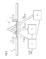
- FIGs 1A, 1B and 2 show a gas burner arrangement 1 for a gas-cooking appliance 10, particularly a gas hob, which comprises at least one gas burner 2, which is adapted to receive a fuel flow from a fuel supply 3 and for providing a fuel-supplied flame 4 to a cooking vessel 5.
- a gas-cooking appliance 10 particularly a gas hob
- the cooking vessel 5 in form of a usual cooking pot is placed on the gas burner 2.
- the cooking vessel 5 is placed on a support 6 arranged adjacent to the gas burner 3 to support the cooking vessel 5 above the flame 4.
- Fig. 1A shows the gas burner arrangement 1 of Fig. 1B without the vessel.
- the gas burner arrangement 1 comprises a thermocouple 7, which is arranged adjacent to the burner 3, particularly adjacent to the fuel-supplied flame (4), such that dependent on whether the cooking vessel 5 is placed above the support 6, or not, the thermocouple signal 8 generated by the thermocouple 7 is changed. Therefore, the thermocouple 7 is arranged such that the thermocouple signal 8 is indicative for whether the cooking vessel 5 is placed above the support 6, particularly above the fuel-supplied flame 4.
- the thermocouple 7 is arranged at a position, which is below a cooking vessel 5 to be placed on the support 6, particularly above the fuel-supplied flame 4.
- thermocouple 7 is thereby adapted to generate a thermocouple signal 8 depending on the thermal state of said thermocouple 7, which particularly depends on whether a vessel 5 is placed above the flame 4 and above the burner 3, or not. It may be particularly seen when Fig. 1A and 1B are viewed vis-à-vis, that the flame structure of the flame 4 is significantly different, if a vessel 5 is placed on the support 6 compared to a situation where no vessel 5 is placed on the support 6. Particularly, the point of contact between the flame 4 and the thermocouple 7 is changed if a vessel 5 is placed on the support 6 compared to a situation where no vessel 5 is placed on the support 6. This change is also changing the thermocouple value.
- thermocouple signal 8 is provided from the thermocouple 7 to the control unit 9, the thermocouple signal 8 is compared to at least one predetermined set value in the control unit, and the control unit generates an output signal 11 dependent on the comparison.
- the output signal 11 thereby is indicative for whether a cooking vessel 5 is placed on the support 6, particularly above the fuel-supplied flame 4, or not.
- the output signal is further provided to at least one signal output device. Said output device can be of various forms, e.g.
- thermocouple signal 8 when comparing the thermocouple signal 8 to the at least one first predetermined set value for at least one first predetermined amount of time, and if the thermocouple signal 8 for the first predetermined amount of time is higher than the at least one first predetermined set value, said output signal 11 is indicative for a state in which a cooking vessel 5 is placed on the support 6, particularly above the fuel-supplied flame 4.
- thermocouple signal 8 to at least one second predetermined set value for at least one second predetermined amount of time, and if the thermocouple signal 8 for the second predetermined amount of time is lower than the at least one second predetermined set value, said generated output signal 11 is indicative for a state in which no cooking vessel 5 is placed on the support 6, particularly above the fuel-supplied flame 4.
- the gas burner arrangement 1 further comprises a control unit 9, which is connected to the thermocouple 7.
- the control unit 9 is adapted to receive the thermocouple signal 8 as an input signal and to process said thermocouple signal 8 to an output signal 11.
- the control unit 9 is capable of determining if the cooking vessel 5 is placed above the support 6 dependent on the thermocouple signal 8.
- the support 6 is arranged such that the cooking vessel 5 is placed above the gas burner 2 with a distance to about 3.0 cm, preferably of about 2.0 cm, more preferably of about 1.0 cm.
- the thermocouple signal 8 is a thermos-tension and/or a thermoelectric current.
- control unit 9 is connected to regulation means 12.
- the regulation means 12 which are provided as electronic valves, are capable of regulating the fuel received by the at least one gas burner 2 from the fuel supply 3, dependent on the output signal 11.
- the an air-gas mixture may be provided, whereby the air is provided by an air actuator means 14, particularly a fan element, and the gas is provided from a gas actuator means 15.
- the control unit 9 is connected to said air actuator means 14 and to said gas actuator means 15.
- the air actuator means 14 is capable of regulating the amount of air in the fuel
- the gas actuator means 15 is capable of regulating the amount of gas in the fuel, dependent on the output signal 11, and particularly be control of the respective valves 12.
- one valve 12 is provided, which is capable of regulating the amount of fuel received by the at least one gas burner 2 from the fuel supply 3, dependent on the output signal 11.
- the control unit 9 is adapted to process the thermocouple signal 8 to an output signal 11, is connected to at least one signal output device 13, which is not shown in the Figs.
- the signal output device 13 is capable of generating a signal dependent on the output signal 11, wherein the signal is perceptible to a user, for example a display informing the user.
Landscapes
- Engineering & Computer Science (AREA)
- Chemical & Material Sciences (AREA)
- Combustion & Propulsion (AREA)
- Mechanical Engineering (AREA)
- General Engineering & Computer Science (AREA)
- Control Of Combustion (AREA)
- Regulation And Control Of Combustion (AREA)
Priority Applications (7)
| Application Number | Priority Date | Filing Date | Title |
|---|---|---|---|
| ES15186148T ES2807581T3 (es) | 2015-09-22 | 2015-09-22 | Disposición de quemador de gas para una cocina de gas con un termopar y procedimiento para determinar si un recipiente de cocción está situado por encima del quemador de gas |
| EP15186148.1A EP3147566B1 (fr) | 2015-09-22 | 2015-09-22 | Système de brûleur à gaz pour une cuisinière à gaz avec un thermocouple et procédé pour déterminer si un ustensile de cuisson est placé sur le brûleur à gaz. |
| AU2016328327A AU2016328327B2 (en) | 2015-09-22 | 2016-07-14 | Gas burner arrangement for a gas-cooking appliance with a thermocouple |
| PCT/EP2016/066713 WO2017050455A1 (fr) | 2015-09-22 | 2016-07-14 | Agencement de brûleur à gaz pour appareil de cuisson au gaz à thermocouple |
| BR112018005350-3A BR112018005350B1 (pt) | 2015-09-22 | 2016-07-14 | Arranjo de queimador de gás, aparelho de cozimento a gás e método para determinar se um recipiente de cozimento é colocado acima de um queimador de gás de um arranjo de queimador de gás de um aparelho de cozimento a gás |
| US15/761,510 US20180274789A1 (en) | 2015-09-22 | 2016-07-14 | Gas burner arrangement for a gas-cooking appliance with a thermocouple |
| CN201680052759.1A CN108027141B (zh) | 2015-09-22 | 2016-07-14 | 用于具有热电偶的燃气烹饪器具的燃气燃烧器装置 |
Applications Claiming Priority (1)
| Application Number | Priority Date | Filing Date | Title |
|---|---|---|---|
| EP15186148.1A EP3147566B1 (fr) | 2015-09-22 | 2015-09-22 | Système de brûleur à gaz pour une cuisinière à gaz avec un thermocouple et procédé pour déterminer si un ustensile de cuisson est placé sur le brûleur à gaz. |
Publications (2)
| Publication Number | Publication Date |
|---|---|
| EP3147566A1 true EP3147566A1 (fr) | 2017-03-29 |
| EP3147566B1 EP3147566B1 (fr) | 2020-05-06 |
Family
ID=54185872
Family Applications (1)
| Application Number | Title | Priority Date | Filing Date |
|---|---|---|---|
| EP15186148.1A Active EP3147566B1 (fr) | 2015-09-22 | 2015-09-22 | Système de brûleur à gaz pour une cuisinière à gaz avec un thermocouple et procédé pour déterminer si un ustensile de cuisson est placé sur le brûleur à gaz. |
Country Status (7)
| Country | Link |
|---|---|
| US (1) | US20180274789A1 (fr) |
| EP (1) | EP3147566B1 (fr) |
| CN (1) | CN108027141B (fr) |
| AU (1) | AU2016328327B2 (fr) |
| BR (1) | BR112018005350B1 (fr) |
| ES (1) | ES2807581T3 (fr) |
| WO (1) | WO2017050455A1 (fr) |
Cited By (1)
| Publication number | Priority date | Publication date | Assignee | Title |
|---|---|---|---|---|
| WO2020120489A1 (fr) * | 2018-12-10 | 2020-06-18 | BSH Hausgeräte GmbH | Système de support de récipient de cuisson ayant un système intégral de surveillance de température et de prévention d'incendie |
Families Citing this family (2)
| Publication number | Priority date | Publication date | Assignee | Title |
|---|---|---|---|---|
| ES2731680A1 (es) * | 2018-05-16 | 2019-11-18 | Bsh Electrodomesticos Espana Sa | Dispositivo de aparato de coccion a gas |
| CN111256172A (zh) * | 2018-11-30 | 2020-06-09 | 宁波方太厨具有限公司 | 一种燃气灶的控制方法及实现该控制方法的燃气灶 |
Citations (8)
| Publication number | Priority date | Publication date | Assignee | Title |
|---|---|---|---|---|
| GB2146804A (en) | 1983-09-20 | 1985-04-24 | Thorn Emi Domestic Appliances | A temperature control arrangement |
| GB2196459A (en) * | 1986-10-16 | 1988-04-27 | Rinnai Kk | A fluid heating apparatus |
| DE4218278A1 (de) * | 1992-06-03 | 1993-12-09 | Seppelfricke Geb Gmbh | Vorrichtung zur Sicherung eines Gaskochstellenbrenners |
| WO2002097333A2 (fr) | 2001-05-25 | 2002-12-05 | BSH Bosch und Siemens Hausgeräte GmbH | Dispositif d'affichage de l'etat thermique d'un rechaud a gaz |
| JP2005077041A (ja) * | 2003-09-02 | 2005-03-24 | Rinnai Corp | ガスコンロ |
| US20100239987A1 (en) | 2009-03-17 | 2010-09-23 | E.G.O. Elektro-Geraetebau Gmbh | Method for controlling a cooking point of a gas oven and device |
| US20140295357A1 (en) * | 2013-03-27 | 2014-10-02 | Electrolux Home Products, Inc. | Cross heating thermocouple based pan sensing |
| DE102013218339A1 (de) * | 2013-09-12 | 2015-03-12 | E.G.O. Elektro-Gerätebau GmbH | Verfahren zur Topferkennung und Gaskochfeld |
Family Cites Families (4)
| Publication number | Priority date | Publication date | Assignee | Title |
|---|---|---|---|---|
| US4481404A (en) * | 1982-12-22 | 1984-11-06 | General Electric Company | Turn-off control circuit for self-cleaning ovens |
| US6705081B2 (en) * | 1997-07-15 | 2004-03-16 | New Power Concepts Llc | System and method for sensor control of the fuel-air ratio in a burner |
| US20150000648A1 (en) * | 2013-06-28 | 2015-01-01 | Chinhu Jung | Portable stove |
| DE102014218741A1 (de) * | 2014-09-18 | 2016-03-24 | E.G.O. Elektro-Gerätebau GmbH | Verfahren zur Topferkennung und Gaskochfeld |
-
2015
- 2015-09-22 EP EP15186148.1A patent/EP3147566B1/fr active Active
- 2015-09-22 ES ES15186148T patent/ES2807581T3/es active Active
-
2016
- 2016-07-14 AU AU2016328327A patent/AU2016328327B2/en active Active
- 2016-07-14 WO PCT/EP2016/066713 patent/WO2017050455A1/fr not_active Ceased
- 2016-07-14 BR BR112018005350-3A patent/BR112018005350B1/pt active IP Right Grant
- 2016-07-14 US US15/761,510 patent/US20180274789A1/en not_active Abandoned
- 2016-07-14 CN CN201680052759.1A patent/CN108027141B/zh active Active
Patent Citations (8)
| Publication number | Priority date | Publication date | Assignee | Title |
|---|---|---|---|---|
| GB2146804A (en) | 1983-09-20 | 1985-04-24 | Thorn Emi Domestic Appliances | A temperature control arrangement |
| GB2196459A (en) * | 1986-10-16 | 1988-04-27 | Rinnai Kk | A fluid heating apparatus |
| DE4218278A1 (de) * | 1992-06-03 | 1993-12-09 | Seppelfricke Geb Gmbh | Vorrichtung zur Sicherung eines Gaskochstellenbrenners |
| WO2002097333A2 (fr) | 2001-05-25 | 2002-12-05 | BSH Bosch und Siemens Hausgeräte GmbH | Dispositif d'affichage de l'etat thermique d'un rechaud a gaz |
| JP2005077041A (ja) * | 2003-09-02 | 2005-03-24 | Rinnai Corp | ガスコンロ |
| US20100239987A1 (en) | 2009-03-17 | 2010-09-23 | E.G.O. Elektro-Geraetebau Gmbh | Method for controlling a cooking point of a gas oven and device |
| US20140295357A1 (en) * | 2013-03-27 | 2014-10-02 | Electrolux Home Products, Inc. | Cross heating thermocouple based pan sensing |
| DE102013218339A1 (de) * | 2013-09-12 | 2015-03-12 | E.G.O. Elektro-Gerätebau GmbH | Verfahren zur Topferkennung und Gaskochfeld |
Cited By (1)
| Publication number | Priority date | Publication date | Assignee | Title |
|---|---|---|---|---|
| WO2020120489A1 (fr) * | 2018-12-10 | 2020-06-18 | BSH Hausgeräte GmbH | Système de support de récipient de cuisson ayant un système intégral de surveillance de température et de prévention d'incendie |
Also Published As
| Publication number | Publication date |
|---|---|
| BR112018005350B1 (pt) | 2022-07-05 |
| WO2017050455A1 (fr) | 2017-03-30 |
| BR112018005350A2 (pt) | 2018-10-09 |
| US20180274789A1 (en) | 2018-09-27 |
| AU2016328327A1 (en) | 2018-02-15 |
| CN108027141A (zh) | 2018-05-11 |
| ES2807581T3 (es) | 2021-02-23 |
| EP3147566B1 (fr) | 2020-05-06 |
| AU2016328327B2 (en) | 2021-12-23 |
| CN108027141B (zh) | 2021-06-11 |
Similar Documents
| Publication | Publication Date | Title |
|---|---|---|
| US10935250B2 (en) | Gas cooking appliance | |
| CN105264295B (zh) | 基于跨距离加热式热电偶的锅感测 | |
| US9909764B2 (en) | Cooking appliance and method for limiting cooking utensil temperatures using dual control modes | |
| EP2783161B1 (fr) | Système de commande et d'allumage de flamme | |
| US20090159068A1 (en) | Fuel-fired barbecue | |
| AU2005203766A1 (en) | Electronic gas cooktop control with simmer system and method thereof | |
| GB2296762A (en) | Cooking appliance | |
| CN110220221A (zh) | 燃气器具燃烧器的火焰监测系统和燃气器具的控制方法 | |
| EP3147566B1 (fr) | Système de brûleur à gaz pour une cuisinière à gaz avec un thermocouple et procédé pour déterminer si un ustensile de cuisson est placé sur le brûleur à gaz. | |
| US7268324B2 (en) | Electric cooking assembly with hot-warning indicator | |
| CN107044658B (zh) | 加热烹调器 | |
| EP2069689A1 (fr) | Dispositif de sécurité pour cuisinière à gaz | |
| US20150020692A1 (en) | Method for operating a gas oven and a gas oven | |
| US20070117058A1 (en) | Control system for the operation of a kitchen oven | |
| JP6722542B2 (ja) | 加熱調理器 | |
| JP6706114B2 (ja) | 加熱調理器 | |
| US20150034625A1 (en) | Cooking appliance and method for controlling the same | |
| KR20150022393A (ko) | 조리기기 | |
| JP6706087B2 (ja) | 加熱調理器 | |
| AU711388B2 (en) | Method and apparatus for the control of flammable fluid heating apparatus | |
| US12607360B2 (en) | Flame rectification circuit system for a gas cooktop | |
| KR101623589B1 (ko) | 조리기기 및 조리기기의 제어방법 | |
| WO2002097333A3 (fr) | Dispositif d'affichage de l'etat thermique d'un rechaud a gaz | |
| KR20010069461A (ko) | 연소량을 자동조절하는 가스레인지 |
Legal Events
| Date | Code | Title | Description |
|---|---|---|---|
| PUAI | Public reference made under article 153(3) epc to a published international application that has entered the european phase |
Free format text: ORIGINAL CODE: 0009012 |
|
| STAA | Information on the status of an ep patent application or granted ep patent |
Free format text: STATUS: THE APPLICATION HAS BEEN PUBLISHED |
|
| AK | Designated contracting states |
Kind code of ref document: A1 Designated state(s): AL AT BE BG CH CY CZ DE DK EE ES FI FR GB GR HR HU IE IS IT LI LT LU LV MC MK MT NL NO PL PT RO RS SE SI SK SM TR |
|
| AX | Request for extension of the european patent |
Extension state: BA ME |
|
| STAA | Information on the status of an ep patent application or granted ep patent |
Free format text: STATUS: REQUEST FOR EXAMINATION WAS MADE |
|
| 17P | Request for examination filed |
Effective date: 20170929 |
|
| RBV | Designated contracting states (corrected) |
Designated state(s): AL AT BE BG CH CY CZ DE DK EE ES FI FR GB GR HR HU IE IS IT LI LT LU LV MC MK MT NL NO PL PT RO RS SE SI SK SM TR |
|
| STAA | Information on the status of an ep patent application or granted ep patent |
Free format text: STATUS: EXAMINATION IS IN PROGRESS |
|
| 17Q | First examination report despatched |
Effective date: 20180718 |
|
| GRAP | Despatch of communication of intention to grant a patent |
Free format text: ORIGINAL CODE: EPIDOSNIGR1 |
|
| STAA | Information on the status of an ep patent application or granted ep patent |
Free format text: STATUS: GRANT OF PATENT IS INTENDED |
|
| INTG | Intention to grant announced |
Effective date: 20191202 |
|
| GRAS | Grant fee paid |
Free format text: ORIGINAL CODE: EPIDOSNIGR3 |
|
| GRAA | (expected) grant |
Free format text: ORIGINAL CODE: 0009210 |
|
| STAA | Information on the status of an ep patent application or granted ep patent |
Free format text: STATUS: THE PATENT HAS BEEN GRANTED |
|
| AK | Designated contracting states |
Kind code of ref document: B1 Designated state(s): AL AT BE BG CH CY CZ DE DK EE ES FI FR GB GR HR HU IE IS IT LI LT LU LV MC MK MT NL NO PL PT RO RS SE SI SK SM TR |
|
| REG | Reference to a national code |
Ref country code: GB Ref legal event code: FG4D |
|
| REG | Reference to a national code |
Ref country code: CH Ref legal event code: EP Ref country code: AT Ref legal event code: REF Ref document number: 1267356 Country of ref document: AT Kind code of ref document: T Effective date: 20200515 |
|
| REG | Reference to a national code |
Ref country code: DE Ref legal event code: R096 Ref document number: 602015052056 Country of ref document: DE |
|
| REG | Reference to a national code |
Ref country code: IE Ref legal event code: FG4D |
|
| REG | Reference to a national code |
Ref country code: LT Ref legal event code: MG4D |
|
| REG | Reference to a national code |
Ref country code: NL Ref legal event code: MP Effective date: 20200506 |
|
| PG25 | Lapsed in a contracting state [announced via postgrant information from national office to epo] |
Ref country code: GR Free format text: LAPSE BECAUSE OF FAILURE TO SUBMIT A TRANSLATION OF THE DESCRIPTION OR TO PAY THE FEE WITHIN THE PRESCRIBED TIME-LIMIT Effective date: 20200807 Ref country code: PT Free format text: LAPSE BECAUSE OF FAILURE TO SUBMIT A TRANSLATION OF THE DESCRIPTION OR TO PAY THE FEE WITHIN THE PRESCRIBED TIME-LIMIT Effective date: 20200907 Ref country code: FI Free format text: LAPSE BECAUSE OF FAILURE TO SUBMIT A TRANSLATION OF THE DESCRIPTION OR TO PAY THE FEE WITHIN THE PRESCRIBED TIME-LIMIT Effective date: 20200506 Ref country code: NO Free format text: LAPSE BECAUSE OF FAILURE TO SUBMIT A TRANSLATION OF THE DESCRIPTION OR TO PAY THE FEE WITHIN THE PRESCRIBED TIME-LIMIT Effective date: 20200806 Ref country code: IS Free format text: LAPSE BECAUSE OF FAILURE TO SUBMIT A TRANSLATION OF THE DESCRIPTION OR TO PAY THE FEE WITHIN THE PRESCRIBED TIME-LIMIT Effective date: 20200906 Ref country code: SE Free format text: LAPSE BECAUSE OF FAILURE TO SUBMIT A TRANSLATION OF THE DESCRIPTION OR TO PAY THE FEE WITHIN THE PRESCRIBED TIME-LIMIT Effective date: 20200506 Ref country code: LT Free format text: LAPSE BECAUSE OF FAILURE TO SUBMIT A TRANSLATION OF THE DESCRIPTION OR TO PAY THE FEE WITHIN THE PRESCRIBED TIME-LIMIT Effective date: 20200506 |
|
| PG25 | Lapsed in a contracting state [announced via postgrant information from national office to epo] |
Ref country code: BG Free format text: LAPSE BECAUSE OF FAILURE TO SUBMIT A TRANSLATION OF THE DESCRIPTION OR TO PAY THE FEE WITHIN THE PRESCRIBED TIME-LIMIT Effective date: 20200806 Ref country code: HR Free format text: LAPSE BECAUSE OF FAILURE TO SUBMIT A TRANSLATION OF THE DESCRIPTION OR TO PAY THE FEE WITHIN THE PRESCRIBED TIME-LIMIT Effective date: 20200506 Ref country code: RS Free format text: LAPSE BECAUSE OF FAILURE TO SUBMIT A TRANSLATION OF THE DESCRIPTION OR TO PAY THE FEE WITHIN THE PRESCRIBED TIME-LIMIT Effective date: 20200506 Ref country code: LV Free format text: LAPSE BECAUSE OF FAILURE TO SUBMIT A TRANSLATION OF THE DESCRIPTION OR TO PAY THE FEE WITHIN THE PRESCRIBED TIME-LIMIT Effective date: 20200506 |
|
| REG | Reference to a national code |
Ref country code: AT Ref legal event code: MK05 Ref document number: 1267356 Country of ref document: AT Kind code of ref document: T Effective date: 20200506 |
|
| PG25 | Lapsed in a contracting state [announced via postgrant information from national office to epo] |
Ref country code: NL Free format text: LAPSE BECAUSE OF FAILURE TO SUBMIT A TRANSLATION OF THE DESCRIPTION OR TO PAY THE FEE WITHIN THE PRESCRIBED TIME-LIMIT Effective date: 20200506 Ref country code: AL Free format text: LAPSE BECAUSE OF FAILURE TO SUBMIT A TRANSLATION OF THE DESCRIPTION OR TO PAY THE FEE WITHIN THE PRESCRIBED TIME-LIMIT Effective date: 20200506 |
|
| PG25 | Lapsed in a contracting state [announced via postgrant information from national office to epo] |
Ref country code: DK Free format text: LAPSE BECAUSE OF FAILURE TO SUBMIT A TRANSLATION OF THE DESCRIPTION OR TO PAY THE FEE WITHIN THE PRESCRIBED TIME-LIMIT Effective date: 20200506 Ref country code: EE Free format text: LAPSE BECAUSE OF FAILURE TO SUBMIT A TRANSLATION OF THE DESCRIPTION OR TO PAY THE FEE WITHIN THE PRESCRIBED TIME-LIMIT Effective date: 20200506 Ref country code: AT Free format text: LAPSE BECAUSE OF FAILURE TO SUBMIT A TRANSLATION OF THE DESCRIPTION OR TO PAY THE FEE WITHIN THE PRESCRIBED TIME-LIMIT Effective date: 20200506 Ref country code: SM Free format text: LAPSE BECAUSE OF FAILURE TO SUBMIT A TRANSLATION OF THE DESCRIPTION OR TO PAY THE FEE WITHIN THE PRESCRIBED TIME-LIMIT Effective date: 20200506 Ref country code: RO Free format text: LAPSE BECAUSE OF FAILURE TO SUBMIT A TRANSLATION OF THE DESCRIPTION OR TO PAY THE FEE WITHIN THE PRESCRIBED TIME-LIMIT Effective date: 20200506 Ref country code: CZ Free format text: LAPSE BECAUSE OF FAILURE TO SUBMIT A TRANSLATION OF THE DESCRIPTION OR TO PAY THE FEE WITHIN THE PRESCRIBED TIME-LIMIT Effective date: 20200506 |
|
| REG | Reference to a national code |
Ref country code: DE Ref legal event code: R097 Ref document number: 602015052056 Country of ref document: DE |
|
| REG | Reference to a national code |
Ref country code: ES Ref legal event code: FG2A Ref document number: 2807581 Country of ref document: ES Kind code of ref document: T3 Effective date: 20210223 |
|
| PG25 | Lapsed in a contracting state [announced via postgrant information from national office to epo] |
Ref country code: PL Free format text: LAPSE BECAUSE OF FAILURE TO SUBMIT A TRANSLATION OF THE DESCRIPTION OR TO PAY THE FEE WITHIN THE PRESCRIBED TIME-LIMIT Effective date: 20200506 Ref country code: SK Free format text: LAPSE BECAUSE OF FAILURE TO SUBMIT A TRANSLATION OF THE DESCRIPTION OR TO PAY THE FEE WITHIN THE PRESCRIBED TIME-LIMIT Effective date: 20200506 |
|
| PLBE | No opposition filed within time limit |
Free format text: ORIGINAL CODE: 0009261 |
|
| STAA | Information on the status of an ep patent application or granted ep patent |
Free format text: STATUS: NO OPPOSITION FILED WITHIN TIME LIMIT |
|
| REG | Reference to a national code |
Ref country code: DE Ref legal event code: R119 Ref document number: 602015052056 Country of ref document: DE |
|
| 26N | No opposition filed |
Effective date: 20210209 |
|
| PG25 | Lapsed in a contracting state [announced via postgrant information from national office to epo] |
Ref country code: MC Free format text: LAPSE BECAUSE OF FAILURE TO SUBMIT A TRANSLATION OF THE DESCRIPTION OR TO PAY THE FEE WITHIN THE PRESCRIBED TIME-LIMIT Effective date: 20200506 |
|
| REG | Reference to a national code |
Ref country code: CH Ref legal event code: PL |
|
| PG25 | Lapsed in a contracting state [announced via postgrant information from national office to epo] |
Ref country code: SI Free format text: LAPSE BECAUSE OF FAILURE TO SUBMIT A TRANSLATION OF THE DESCRIPTION OR TO PAY THE FEE WITHIN THE PRESCRIBED TIME-LIMIT Effective date: 20200506 |
|
| REG | Reference to a national code |
Ref country code: BE Ref legal event code: MM Effective date: 20200930 |
|
| PG25 | Lapsed in a contracting state [announced via postgrant information from national office to epo] |
Ref country code: LU Free format text: LAPSE BECAUSE OF NON-PAYMENT OF DUE FEES Effective date: 20200922 |
|
| PG25 | Lapsed in a contracting state [announced via postgrant information from national office to epo] |
Ref country code: DE Free format text: LAPSE BECAUSE OF NON-PAYMENT OF DUE FEES Effective date: 20210401 |
|
| PG25 | Lapsed in a contracting state [announced via postgrant information from national office to epo] |
Ref country code: LI Free format text: LAPSE BECAUSE OF NON-PAYMENT OF DUE FEES Effective date: 20200930 Ref country code: IE Free format text: LAPSE BECAUSE OF NON-PAYMENT OF DUE FEES Effective date: 20200922 Ref country code: BE Free format text: LAPSE BECAUSE OF NON-PAYMENT OF DUE FEES Effective date: 20200930 Ref country code: CH Free format text: LAPSE BECAUSE OF NON-PAYMENT OF DUE FEES Effective date: 20200930 |
|
| PG25 | Lapsed in a contracting state [announced via postgrant information from national office to epo] |
Ref country code: TR Free format text: LAPSE BECAUSE OF FAILURE TO SUBMIT A TRANSLATION OF THE DESCRIPTION OR TO PAY THE FEE WITHIN THE PRESCRIBED TIME-LIMIT Effective date: 20200506 Ref country code: MT Free format text: LAPSE BECAUSE OF FAILURE TO SUBMIT A TRANSLATION OF THE DESCRIPTION OR TO PAY THE FEE WITHIN THE PRESCRIBED TIME-LIMIT Effective date: 20200506 Ref country code: CY Free format text: LAPSE BECAUSE OF FAILURE TO SUBMIT A TRANSLATION OF THE DESCRIPTION OR TO PAY THE FEE WITHIN THE PRESCRIBED TIME-LIMIT Effective date: 20200506 |
|
| PG25 | Lapsed in a contracting state [announced via postgrant information from national office to epo] |
Ref country code: MK Free format text: LAPSE BECAUSE OF FAILURE TO SUBMIT A TRANSLATION OF THE DESCRIPTION OR TO PAY THE FEE WITHIN THE PRESCRIBED TIME-LIMIT Effective date: 20200506 |
|
| P01 | Opt-out of the competence of the unified patent court (upc) registered |
Effective date: 20230625 |
|
| PGFP | Annual fee paid to national office [announced via postgrant information from national office to epo] |
Ref country code: IT Payment date: 20250922 Year of fee payment: 11 |
|
| PGFP | Annual fee paid to national office [announced via postgrant information from national office to epo] |
Ref country code: GB Payment date: 20250923 Year of fee payment: 11 |
|
| PGFP | Annual fee paid to national office [announced via postgrant information from national office to epo] |
Ref country code: FR Payment date: 20250925 Year of fee payment: 11 |
|
| PGFP | Annual fee paid to national office [announced via postgrant information from national office to epo] |
Ref country code: ES Payment date: 20251015 Year of fee payment: 11 |