EP3147568B1 - Axial gestufte mikromixerkappe und betriebsverfahren dafür - Google Patents
Axial gestufte mikromixerkappe und betriebsverfahren dafür Download PDFInfo
- Publication number
- EP3147568B1 EP3147568B1 EP16187403.7A EP16187403A EP3147568B1 EP 3147568 B1 EP3147568 B1 EP 3147568B1 EP 16187403 A EP16187403 A EP 16187403A EP 3147568 B1 EP3147568 B1 EP 3147568B1
- Authority
- EP
- European Patent Office
- Prior art keywords
- fuel
- combustion
- stage
- inner plate
- air
- Prior art date
- Legal status (The legal status is an assumption and is not a legal conclusion. Google has not performed a legal analysis and makes no representation as to the accuracy of the status listed.)
- Active
Links
Images









Classifications
-
- F—MECHANICAL ENGINEERING; LIGHTING; HEATING; WEAPONS; BLASTING
- F23—COMBUSTION APPARATUS; COMBUSTION PROCESSES
- F23R—GENERATING COMBUSTION PRODUCTS OF HIGH PRESSURE OR HIGH VELOCITY, e.g. GAS-TURBINE COMBUSTION CHAMBERS
- F23R3/00—Continuous combustion chambers using liquid or gaseous fuel
- F23R3/28—Continuous combustion chambers using liquid or gaseous fuel characterised by the fuel supply
- F23R3/286—Continuous combustion chambers using liquid or gaseous fuel characterised by the fuel supply having fuel-air premixing devices
-
- F—MECHANICAL ENGINEERING; LIGHTING; HEATING; WEAPONS; BLASTING
- F23—COMBUSTION APPARATUS; COMBUSTION PROCESSES
- F23R—GENERATING COMBUSTION PRODUCTS OF HIGH PRESSURE OR HIGH VELOCITY, e.g. GAS-TURBINE COMBUSTION CHAMBERS
- F23R3/00—Continuous combustion chambers using liquid or gaseous fuel
- F23R3/02—Continuous combustion chambers using liquid or gaseous fuel characterised by the air-flow or gas-flow configuration
-
- F—MECHANICAL ENGINEERING; LIGHTING; HEATING; WEAPONS; BLASTING
- F23—COMBUSTION APPARATUS; COMBUSTION PROCESSES
- F23R—GENERATING COMBUSTION PRODUCTS OF HIGH PRESSURE OR HIGH VELOCITY, e.g. GAS-TURBINE COMBUSTION CHAMBERS
- F23R3/00—Continuous combustion chambers using liquid or gaseous fuel
- F23R3/02—Continuous combustion chambers using liquid or gaseous fuel characterised by the air-flow or gas-flow configuration
- F23R3/04—Air inlet arrangements
- F23R3/10—Air inlet arrangements for primary air
-
- F—MECHANICAL ENGINEERING; LIGHTING; HEATING; WEAPONS; BLASTING
- F23—COMBUSTION APPARATUS; COMBUSTION PROCESSES
- F23R—GENERATING COMBUSTION PRODUCTS OF HIGH PRESSURE OR HIGH VELOCITY, e.g. GAS-TURBINE COMBUSTION CHAMBERS
- F23R2900/00—Special features of, or arrangements for continuous combustion chambers; Combustion processes therefor
- F23R2900/03041—Effusion cooled combustion chamber walls or domes
Definitions
- This invention relates generally to gas turbine systems, particularly to a micromixer cap of an industrial gas turbine engine, and a method to distribute a mixture of fuel and air to a combustion chamber in a gas turbine engine.
- An industrial gas turbine includes an air inlet, an air compressor section, a combustion section, a turbine section, and an exhaust section.
- the combustion section includes fuel feeds and air feed that connect to combustion cans, which mixes the fuel and the air and creates combustion that supplies exhaust gas to the turbine section.
- the combustion cans include a series of fuel tubes under an endcover in an axial end of a combustion can, a combustion chamber on the opposite axial end of the combustion can, and a variety of configurations of mixing nozzles that mixes fuel with air prior to reaching the combustion chamber.
- the mixing nozzles may also be micromixer configurations using the standard endcover and fuel nozzle setup to feed fuel to the micromixer tubes.
- the current micromixer configuration restricts the flexibility of the micromixer configuration by limiting the shape of the micromixer assembly to conform to the rounded shape of the combustion can that is tied to the fuel nozzle sector geometry and the designated fuel entry points.
- the current configurations also poses mechanical challenges of connecting the endcover and fuel nozzle feed to the mixing nozzles and/or micromixer assemblies inside the combustion can.
- US 2013/213051 A1 relates to a combustor with the features of the subject-matter of the preamble of claim 1, having a plurality of micromixer tubes extending between an upstream air plenum and a downstream combustion chamber.
- US 2014/338344 A1 and US 2014/338354 A1 relate to multi-tube fuel nozzles.
- Simplification and control of the fuel tubes and mixing nozzles configurations have been in constant need of development.
- the improvements are sought in order to improve control of the amount of fuel used during combustion, and to improve control of the amount of combustion that is produced during operation.
- the simplification of the fuel input also allows easier connections from the fuel nozzle feed to the mixing nozzles and/or micromixer assemblies inside the combustion can.
- the simplification may allow the combustion can to be re-shaped to better match the annular sector of the turbine inlet instead of remaining round and tied to fuel nozzle geometry.
- the flexibility in micromixer configurations may allow further optimization of dynamics and emissions while maintaining traditional effusion cooling of the micromixer cap to limit durability risks. Costs may also be reduced due to the simplification of configurations.
- the invention provides an axially stacked configuration of fuel input in a combustion can.
- Fuel is provided in axially stacked fuel stages under the combustor endcover.
- the fuel stages include micromixer tubes that extends through the multiple fuel stages, and the micromixer tubes are initially filled with air.
- Fuel enters each of the fuel stages from a radial direction of the combustion can, from an inlet on a radially outer periphery of the fuel stages, and the fuel surrounds the micromixer tubes that extends through the fuel stages from one side of the stack of fuel stages that abuts the combustion chamber, to the opposite side of the stack of fuel stages that abuts an air plenum.
- the air plenum is located in place of where conventional fuel injector feed tubes would have been placed.
- the micromixer tubes are initially filled with air supplied by the air plenum, which receives compressed air from the compressor section. Fuel enters the micromixer tubes from an injection hole in the micromixer tubes that is located in close proximity to the edge of the micromixer tube. This ensures that the fuel has ample distance in the micromixer tube to mix with the air in the tubes prior to entering the combustion chamber.
- the inventive configuration of the axially stacked fuel stages simplifies the combustion can by removing the fuel nozzles while retaining fuel staging capability.
- the configuration provides a more space efficient and fuel efficient way of mixing fuel and air, and supplying the mixture of fuel and air to the combustion chamber.
- the inventive configuration allows for a more steady supply of compressed air to the micromixer tubes to ensure thorough mixing of air and fuel within the micromixer tubes prior to entering the combustion chamber.
- FIG. 1 A schematic view of the inventive combustion can configuration is shown in Figure 1 .
- the combustion can 10 is connected to an exhaust path 20 that directs exhaust gas in the flow direction F to a turbine section downstream of the combustion can.
- the combustion can includes a combustion chamber 101, and axially stacked fuel stage stack 103, and an air plenum 105.
- the fuel stage stack 103 is operatively connected to a fuel feed 120.
- the combustion chamber 101 is surrounded by a combustion liner 107, which is covered by a flow sleeve 109.
- a compressor airflow 131 flows in a flow path 142 formed between the flow sleeve 109 and combustion liner 107.
- the compressor airflow 131 is supplied by a compressor section 130 of the industrial gas turbine.
- the compressed airflow 131 flows through the fuel stage stack 103 into an air plenum 105 that is enclosed by end cover 111 and fuel stack 103.
- the combustion can 10 has an axis A, which follows the flow direction F of the exhaust gas that exits the combustion can from the combustion chamber, and a radius R that extends from the axis A.
- Compressed airflow 131 enters a flow path 142 between the flow sleeve 109 and the combustion liner 107 through an air inlet 140 in the flow sleeve 109.
- the compressed airflow 131 passes through air channels 201 in the fuel stage stack 103 into the air plenum 105 that is defined by the endcover 111.
- the compressed air 131 fills micromixer tubes 210 that extend through the fuel stage stack 103 in the flow direction F towards the combustion chamber 101.
- the fuel stage stack 103 includes multiple fuel stages, and each of the fuel stages may be connected to individual control valves 31, 33, and 35 that control the amount of fuel entering each of the fuel stages, respectively. After air and fuel are mixed within the micromixer tubes 210, the mixture enters the combustion chamber 101 to be combusted to create an exhaust flow that follows an axial direction A of the combustion can.
- the fuel stage stack 103 includes fuel stages that are axially stacked with respect to the combustion can, and the fuel inlets of the fuel stages are located on the radially outermost portion of the fuel stages as shown in the subsequent figures.
- the fuel stage stack 103 may be bolted together and fixed to other stationary structures using multiple bolts 115.
- the bolts 115 may also be used to seal the end cover 111 to the fuel stage stack 103, and engage the fuel stage stack 103 with the flow sleeve 109.
- the bolts 115 are located on the radially outermost perimeter of the fuel stage stack 103. Even if not shown in the subsequent figures, the bolts 115 may be applied to each of the fuel stages accordingly.
- the fuel stage stack 103 may include a sealing flange 113 that extends along a periphery of the fuel stage stack 103.
- the sealing flange 113 operatively connects the fuel stage stack 103 to the combustion liner 107, and may act as a seal or support between the fuel stage stack 103 and the combustion chamber 101.
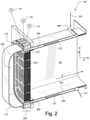
- Each fuel stage in the fuel stage stack 103 includes an annular portion 213 that houses numerous air channels 201, and the air channels 201 are placed along the radially outer perimeter of inner plates 203, 205, 207, 209, and 211 that divide each of the fuel stages 240, 250, and 260.
- the fuel stages 240, 250, and 260 may also be known as pre-mix stages such as being called pre-mix 1, pre-mix 2, and pre-mix 3, or as PM1, PM2, and PM3.
- the bolts 115 that are shown in Figure 2 may be applied to the radially outermost perimeter of the annular portion 213 to engage the fuel stages together and keep the different combustion can structures in place.
- Micromixer tubes 210 extend through air stage 230 and fuel stages 240, 250, and 260, and may be open throughout from the air plenum 105 to the combustion chamber 101.
- the micromixer tubes 210 may be distributed uniformly in the radial direction of the combustion can 10. Alternatively, the micromixer tubes 210 may be distributed in different configurations that are non-linear. Micromixer tubes 210 may have additional features that enhance air/fuel mixing which vary from straight cylindrical tubes.
- the combustion-side inner plate 203 provides a full divider between the air stage 230 and the combustion chamber 101, except for effusion cooling holes 235 that is shown in Figure 8 .
- the first inner plate 205 provides a divider between first fuel stage 240 and the air stage 230.
- the first inner plate 205 extends the entire radius of the inner plate, and creates a full vertical divider in the fuel stage stack 103.
- the second inner plate 207 provides a divider between the second fuel stage 250 and the first fuel stage 240.
- the second inner plate 207 extends farther towards the inner radius of the inner plates than the third inner plate 209.
- the third inner plate 209 is the second inner plate in the fuel stage stack 103 in the flow direction F.
- the third inner plate 209 provides a divider between the third fuel stage 260 and the second fuel stage 250.
- the third inner plate 209 may only extend a short distance along the radially outer perimeter of the inner plates.
- the fourth inner plate 211 abuts the air plenum 105 as shown in Figures 1 and 2 .
- the fourth inner plate 211 is the first inner plate in the flow direction F.
- the micromixer tubes 210 receive air flow from openings on the fourth inner plate 211.
- the fourth inner plate 211 creates a divider between the air plenum 105 and the chambers inside the fuel stages 240, 250, and 260.
- the air channels 201 extends through fuel stages 260, 250, 240, and air stage 230.
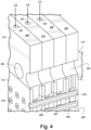
- Each of the fuel stages 260, 250 and 240 have a fuel inlet 261, 251, and 241, respectively, in the radially outermost portion edge of the annular portion 213.
- Air stage 230 does not have a corresponding fuel inlet in the same respective location as the other fuel stages, instead, air stage 230 is being fed air by passage 231.
- Each of the fuel stages 260, 250 and 240 may receive the same type of fuel, or different types of fuel, to be supplied into the respective fuel stages.
- Figure 5 shows an exploded and simplified view of each of the fuel stages and inner plates, without the micromixer tubes or their penetrations. Details of each of the inner plates are shown, particularly for the second inner plate 207 and the third inner plate 209.
- the fourth inner plate 211 may be seen as an end plate for the third fuel stage 260 and the fuel stage stack 103 overall.
- the separate plates and fuel stages are expanded in this figure to show detail.
- the actual fuel stage stack 103 may be made of multiple separate pieces or may be printed as a unit, such as being manufactures by Direct Metal Laser Melting (DMLM) process or other comparable processes.
- DMLM Direct Metal Laser Melting
- the combustion-side inner plate 203 can be seen as an end plate for the air stage 230 and the fuel stage stack 103 overall.
- the combustion-side inner plate 203 is a vertical plate that extends through the entire radius of the fuel stage.
- the combustion-side inner plate 203 defines a chamber between the combustion-side inner plate 203, the annular portion 213, and the first inner plate 205.
- the chamber for the air stage 230 has the same width as a single fuel stage throughout the chamber.
- the combustion- side inner plate 203 includes effusion cooling holes 235 that allows cooling air from the air stage 230 chamber to enter the combustion chamber 101.
- the first inner plate 205 extends from the radially outermost edge of the inner plate (or extends from the radially innermost edge of the annular portion) towards the axis of the combustor can, and extends through the axial center of the combustion can.
- the first inner plate 205 may be seen as a radial inner plate that divides between the first fuel stage 240 and air stage 230.
- the radially inner edge of the second inner plate 207 includes a lip 245 that defines a chamber in the first fuel stage 240 that is located between the lip 245, the first inner plate 205, the annular portion 213, the second inner plate 207, the lip 245 on the second inner plate 207, and the fourth inner plate 211.
- the chamber for first fuel stage 240 has a one-fuel-stage width between the second inner plate 207 and the first inner plate 205 in the radially outermost portion of the inner plates, and the chamber for the first fuel stage 240 has a three-fuel-stage width in the radially innermost portion on the axially center portion within the lip 245.
- the chamber receives the fuel supply 123 that enters through fuel inlet 251 for second fuel stage 250.
- the second inner plate 207 extends from the radially outermost edge of the inner plate (or extends from the radially innermost edge of the annular portion) towards the axis of the combustor can, but does not extend to the axial center of the combustion can.
- the radially inner edge of the second inner plate 207 includes a lip 245 that defines a chamber in the second fuel stage 250 that is located between the lip 245, the second inner plate 207, the third inner plate 209, the annular portion 213, and the third inner plate 209.
- the lip 245 has a two-fuel-stage width that extends in the axial direction.
- the lip 245 on the second inner plate 207 has double the width of the lip 255 on the third inner plate 209.
- the lip 245 extends beyond the lip 255 in the fuel stage stack, and seals the chamber for second fuel stage 250 with the fourth inner plate 211.
- the chamber for second fuel stage 250 has a one-fuel-stage width between the third inner plate 209 and the second inner plate 207 on the radially outermost portion of the inner plates, and has a two-fuel-stage width between the lip 255 and lip 245 on the radially inner portion of the inner plates.
- the chamber for second fuel stage 250 receives the fuel supply 123 that enters through the fuel inlet 251.
- the third inner plate 209 extends from the radially outermost edge of the inner plate (or extends from the radially innermost edge of the annular portion) towards the axis of the combustor can, but does not extend to the axial center of the combustion can.
- the third inner plate 209 extends from the outer most radial edge of the inner plates towards the axis of the combustion can.
- the radially inner edge of the third inner plate 209 includes a lip 255 that defines a chamber in the third fuel stage 260 that is located between the lip 255, the third inner plate 209, the annular portion 213, and the fourth inner plate 211.
- the lip 255 may have a one-fuel-stage width in the axial direction of the combustion can. In other words, the chamber has a one-fuel-stage width.
- the chamber for third fuel stage 260 receives the fuel supply 125 that enters through the fuel inlet 261.
- lip 245 The area enclosed by lip 245 is sized to permit the first fuel stage 240 micromixer tubes to pass through.
- the area between lips 255 and 245 is sized to permit the second fuel stage 250 micromixer tubes to pass through.
- the area enclosed by the outer radial perimeter of plate 209 and lip 255 is sized to permit third fuel stage micromixer tubes to pass through.
- Air stage 230 is provided in cross-section in Figures 6-9 .
- the air stage 230 includes an annular portion 213 that houses numerous air channels 201 on the inner perimeter of the annular portion 213.
- an air chamber 233 for the air stage 230 receives air from the air channel 201 through air passage 231 that is provided at each of the air channels 201 into the air chamber 233.
- a second air flow 133 is divided from the compressed air 131 to pass through the air passage 231 and to enter the air chamber 233 that is defined by the combustion-side inner plate 203, the annular portion 213, and the first inner plate 205.
- the second air flow 133 creates a cooling flow barrier between the combustion chamber 101 and the fuel stages 240, 250, and 260.
- Pin holes 235 may be added to provide air passages between air stage 230 to the combustion chamber 101.
- the pin holes 235 extend through the combustion-side inner plate 203, and may provide a third air flow 135 that is used to cool the surface of the combustion-side inner plate 203 in the combustion chamber 101.
- a micromixer tube is used to premix air and fuel in an efficient way by providing an air conduit that includes a fuel inlet on an upstream portion of the air conduit, and allowing the fuel to mix with the air inside the micromixer tube, for example, with the aid of a kink in the tube that forces the air and fuel from a laminar flow to a turbulent flow prior to exiting the tube.
- all of the micromixer tubes 210 in the fuel stage stack 103 extends through each of the fuel stages 240, 250 and 260.
- the micromixer tubes 210 are zoned according to each of the different fuel chambers and fuel stage from which the micromixer tubes 210 would receive fuel.
- the micromixer tubes 210 are zoned in a concentric configuration in a radial direction of the combustion can.
- the radially outermost zone 269 of the micromixer tubes 210 receives fuel from the third fuel stage 260, the radially intermediate zone 259 of the micromixer tubes 210 receives fuel from the second fuel stage 250, and the radially innermost zone 249 of the micromixer tubes 210 receives fuel from the first fuel stage 240.
- the first fuel stage 240 is depicted schematically in cross-section in Figures 10-12 .
- the first fuel stage 240 includes an annular portion 213 that houses numerous air channels 201 on the inner perimeter of the annular portion 213. The compressed air from the air channels 201 do not enter the first fuel stage 240.
- a fuel inlet 241 is provided on the radially outermost edge of the annular portion 213 for the first fuel stage 240.
- First fuel 121 may enter the fuel inlet 241, and fill the first fuel chamber 243 for the first fuel stage 240.
- the first fuel 121 only fills the first fuel chamber 243 as defined by the first inner plate 205, the annular portion 213, the second inner plate 207, the lip 245, and the fourth inner plate 211 that closes the first fuel chamber 243.
- the first fuel chamber 243 extends three fuel stages wide from the first inner plate 205 to the fourth inner plate 211.
- the micromixer tubes 210 that are applied in the radially innermost zone 249 extends through the entire fuel stage stack 103, and are immersed in the first fuel 121 in the first fuel chamber 243 that is three stages wide in the axial direction.
- the first fuel 121 fills the first fuel chamber 243 and provides fuel to the micromixer tube 210 through at least one injection holes 215 on the micromixer tube 210 on an upstream portion of the micromixer tube 210, preferably as close to the inlet of the micromixer tube 210 as possible to ensure sufficient time in the micromixer to tube create a mixture 280 of the air flow 139 and the first fuel 121 thoroughly prior to exiting the micromixer tube 210 into the combustion chamber 101.
- the first fuel 121 travels the width of three fuel stages in first fuel chamber 243 for first fuel stage 240.
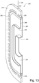
- the second fuel stage 250 is depicted schematically in cross- section in Figures 13-15 .
- the second fuel stage 250 includes an annular portion 213 that houses numerous air channels 201 on the inner perimeter of the annular portion 213. The compressed air from the air channels 201 do not enter the second fuel stage 250.
- a fuel inlet 251 is provided on the radially outermost edge of the annular portion 213 for the second fuel stage 250.
- Second fuel 123 may enter the fuel inlet 251, and fill the second fuel chamber 253 for the second fuel stage 250.
- the second fuel 123 only fills the second fuel chamber 253 as defined by the second inner plate 207, the lip 245, the annular portion 213, the third inner plate 209, the lip 255, and the fourth inner plate 211 that closes the second fuel chamber 253.
- the second fuel chamber 253 extends two fuel stages wide between lip 245 and lip 255 from the second inner plate 207 to the fourth inner plate 211.
- the micromixer tubes 210 that are applied in the radially intermediate zone 259 extends through the entire fuel stage stack 103, and are immersed in the second fuel 123 in the second fuel chamber 253 that is two stages wide in the axial direction.
- the second fuel 123 fills the second fuel chamber 253 and provides fuel to the micromixer tube 210 through at least one injection holes 215 on the micromixer tube 210 on an upstream portion of the micromixer tube 210, preferably as close to the inlet of the micromixer tube 210 as possible to ensure sufficient time in the micromixer to tube create a mixture 280 of the airflow 139 and the second fuel 123 thoroughly prior to exiting the micromixer tube 210 into the combustion chamber 101.
- the second fuel 123 travels the width of two fuel stages in second fuel chamber 253 for second fuel stage 250.
- the third fuel stage 260 is depicted schematically in cross-section in Figures 16-18 .
- the third fuel stage 260 includes an annular portion 213 that houses numerous air channels 201 on the inner perimeter of the annular portion 213. The compressed air from the air channels 201 does not enter the third fuel stage 260.
- a fuel inlet 261 is provided on the radially outermost edge of the annular portion 213 for the third fuel stage 260.
- Third fuel 125 may enter the fuel inlet 261, and fill the third fuel chamber 263 for the third fuel stage 260.
- the third fuel 125 only fills the third fuel chamber 263 as defined by the second inner plate 209, the lip 255, the annular portion 213, and the fourth inner plate 211 that closes the third fuel chamber 263.
- the third fuel chamber 263 extends one fuel stage wide from the second inner plate 209 to the fourth inner plate 211, defined by lip 255.
- fuel may be distributed to different portions of the third fuel chamber 263 through fuel distribution holes 267.
- the fuel distribution holes may also be present in the first fuel chamber 243 and the second fuel chamber 253 to distribute the first fuel 121 and the second fuel 123, respectively.
- Figure 17 shows that the micromixer tubes 210 that are applied in the radially outermost zone 269 extends through the entire fuel stage stack 103, and are immersed in the third fuel 125 in the third fuel chamber 263 that is only one stage wide in the axial direction.
- the third fuel 125 fills the third fuel chamber 263 and provides fuel to the micromixer tube 210 through at least one injection holes 215 on the micromixer tube 210 on an upstream portion of the micromixer tube 210, preferably as close to the inlet of the micromixer tube 210 as possible to ensure sufficient time in the micromixer to tube create a mixture 280 of the air flow 139 and the third fuel 125 thoroughly prior to exiting the micromixer tube 210 into the combustion chamber 101.
- the third fuel 125 travels the width of one fuel stage in third fuel chamber 263 for third fuel stage 260.
- the injection holes 215 on the micromixer tubes 210 are preferably located on the same axial plane in all of the radially outermost zone 269, the radially intermediate zone 259, and the radially innermost zone 249.
- the present configuration provides a method of controlling the rate of combustion by having the ability to provide fuel to only selective portions of the micromixer tubes through the fuel stages.
- fuel may be only provided to first fuel stage 240 such that only the radially innermost zone 249 of micromixer tubes receive fuel supply, and thus only the radially innermost zone 249 would provide a mixture of fuel and air for combustion.
- the other two fuel stages and corresponding micromixer tube zones may only provide air supply to the combustion chamber.
- the same technique can be applied to the fuel stages in various combinations.
- the amount of fuel supplied to the fuel stage stack may also be varied depending on the preferred settings during combustion.
- the micromixer tubes 210 may have a multi-tau configuration such that the micromixer tubes 210 in the different radial zones are in different heights inside the air plenum 105.
- the Fourth inner plate 211 follows the multi- tau configuration of the micromixer tubes 210.
- Figure 19 shows an example of a linear configuration, in which the radially innermost zone 249 protrudes out the farthest from the fourth inner plate 211 into the air plenum 105, the radially intermediate zone 259 protrudes a shorter distance out of the fourth inner plate 211 than the radially innermost zone 249, and the radially outermost zone 269 does not protrude out of the fourth inner plate 211.
- Figure 20 shows another multi-tau configuration, in which the micromixer tubes 210 in the radial zones are provided in varying heights.
- Other multi-tau configuration may also be employed as preferred for the combustion needs of the industrial gas turbine.
- Multi-tau micromixer tubes refer to tubes of different lengths. This is done to vary the acoustic length of the tubes, preventing combustion tones from developing based on a singular tube acoustic length.
- the multi-tau configuration provides another method for tuning the combustion system away from potentially damaging combustion dynamics.
- the fuel stages shown in this application is one configuration that may be used, with three fuel stages in the fuel stage stack. There may be one or more fuel stages in the fuel stage stack. The maximum fuel stages is determined by the complexity of the configuration desired and combustion needs at the time.
- the fuel stages may have an axial width that is needed for packaging of the micromixer tubes in each of the respective fuel stages.
Landscapes
- Engineering & Computer Science (AREA)
- Chemical & Material Sciences (AREA)
- Combustion & Propulsion (AREA)
- Mechanical Engineering (AREA)
- General Engineering & Computer Science (AREA)
Claims (9)
- Verbrennungsdose (10) mit einer Achse in der Strömungsrichtung (F) der Verbrennungsdose (10), umfassend:eine Brennkammer (101), die durch eine Verbrennungsauskleidung (107) definiert ist;einen Brennstoffstufenstapel (103) stromaufwärts der Brennkammer (101) mit mindestens einer Luftstufe (230) und einer ersten Brennstoffstufe (240), die in einer axialen Richtung (A) gestapelt sind, wobei die erste Brennstoffstufe umfassteinen ringförmigen Abschnitt (213) an dem radial äußersten Umfang der ersten Brennstoffstufe (240);einen Brennstoffeinlass (241) auf der radialen Außenoberfläche des ringförmigen Abschnitts (213); undeine Brennstoffkammer (243), die durch eine erste innere Platte (205), eine zweite innere Platte (207) und den ringförmigen Abschnitt (213) definiert ist;eine Luftkammer (105) stromaufwärts des Brennstoffstufenstapels (103), die durch eine Endabdeckung (111) definiert ist;mehrere Mikromixerrohre (210), die eine Fluidverbindung zwischen der Luftkammer (105) und der Brennkammer (101) herstellen und sich durch den Brennstoffstufenstapel (103) erstrecken;dadurch gekennzeichnet, dass die zweite innere Platte (207) eine Lippe (245) einschließt, die sich über eine Breite von zwei Brennstoffstufen in der axialen Richtung (A) erstreckt, wobei die Lippe (245) eine erste Brennstoffkammer (243) mit der ersten inneren Platte (205) und der zweiten inneren Platte (207) bildet, wobei die erste Brennstoffkammer (243) eine Breite von drei Brennstoffstufen in einem radial mittleren Abschnitt (249) des Brennstoffstufenstapels (103) aufweist.
- Verbrennungsdose nach dem vorstehenden Anspruch, ferner umfassend eine zweite Brennstoffstufe (250), die durch die zweite innere Platte (207) aus der ersten Brennstoffstufe (240) und eine dritte innere Platte (209) definiert ist, wobei die dritte innere Platte (209) eine Lippe (255) einschließt, die sich über eine Breite einer Brennstoffstufe in der axialen Richtung (A) erstreckt, die dritte innere Plattenlippe (255) und die zweite innere Plattenlippe (245) mit der zweiten inneren Platte (207) und der dritten inneren Platte (209) eine Kammer bilden, wobei die Kammer eine Breite von zwei Brennstoffstufen in einem radial mittleren Abschnitt (259) des Brennstoffstufenstapels (103) aufweist.
- Verbrennungsdose nach dem vorstehenden Anspruch, ferner umfassend eine dritte Brennstoffstufe (260), die durch die dritte innere Platte (209) aus der zweiten Brennstoffstufe (250) und eine vierte innere Platte (211) definiert ist, wobei die vierte innere Platte (211) mit dem ringförmigen Abschnitt (213), der dritten inneren Platte (209) und der Lippe der dritten inneren Platte (255) eine Kammer bildet, wobei die Kammer eine Breite von einer Brennstoffstufe in einem radial äußersten Abschnitt (269) des Brennstoffstufenstapels (103) aufweist.
- Verbrennungsdose (10) nach Anspruch 1, ferner umfassend einen Luftdurchgang (142), der durch eine radiale Außenoberfläche der Verbrennungsauskleidung (107) und eine radiale Innenoberfläche einer die Verbrennungsauskleidung (107) bedeckenden (109) äußeren Hülse definiert ist, wobei der Luftdurchgang (231) dem Luftkanal (201) und der Luftkammer (105) Luftstrom zuführt.
- Verbrennungsdose (10) nach einem der vorstehenden Ansprüche, wobei die Luftstufe (230) eine verbrennungsseitige innere Platte (203) in der Brennkammer (101) einschließt, die Stiftlöcher (235) umfasst, die der Oberfläche der verbrennungsseitigen inneren Platte (203), die der Brennkammer (101) zugewandt ist, einen Kühlstrom zuführen.
- Verbrennungsdose (10) nach einem der vorstehenden Ansprüche, wobei jedes der Mikromixerrohre (210) ein Einspritzloch (215) zum Eintritt von Brennstoff in die Mikromixerrohre (210) einschließen und alle Einspritzlöcher (215) an den Mikromixerrohren (210) in derselben axialen Ebene an einem stromaufwärtigen Abschnitt der Mikromixerrohre (210) angeordnet sind.
- Verbrennungsdose (10) nach Anspruch 2 oder Anspruch 3 oder einem der Ansprüche 5 und 6, wenn abhängig von mindestens Anspruch 2, wobei die erste Brennstoffkammer (243) der ersten Brennstoffstufe (240), eine zweite Brennstoffkammer (253) der zweiten Brennstoffstufe (250) und eine dritte Brennstoffkammer (263) einer/der dritten Brennstoffstufe (260) voneinander getrennt sind.
- Verfahren zum Zuführen eines Gemischs aus Brennstoff und Luft zu einer Brennkammer (101) zur Verbrennung in einer Verbrennungsdose (10), wobei die Verbrennungsdose umfassteine Brennkammer (101), die durch eine Verbrennungsauskleidung (107) definiert ist;einen Brennstoffstufenstapel (103) stromaufwärts der Brennkammer (101), der mindestens zwei axial gestapelte Brennstoffstufen (240, 250, 260) mit Brennstoffkammern (243, 253, 263) und mindestens eine Luftstufe (230) einschließt, die in einer axialen Richtung (A) gestapelt sind, wobei der Brennstoffstufenstapel eine erste Brennstoffstufe (240) umfasst, wobei die erste Brennstoffstufe umfassteinen ringförmigen Abschnitt (213) an dem radial äußersten Umfang der ersten Brennstoffstufe (240);einen Brennstoffeinlass (241) auf der radialen Außenoberfläche des ringförmigen Abschnitts (213); undeine Brennstoffkammer (243), die durch eine erste innere Platte (205), eine zweite innere Platte (207) und den ringförmigen Abschnitt (213) definiert ist;eine Luftkammer (105) stromaufwärts des Brennstoffstufenstapels (103), die durch eine Endabdeckung (111) definiert ist;mehrere Mikromixerrohre (210), die sich durch den Brennstoffstufenstapel (103) erstrecken und eine Fluidverbindung zwischen der Luftkammer (105) und der Brennkammer (101) in der axialen Richtung (A) herstellen;wobei das Verfahren umfasst:
Zuführen von Druckluft zu der Luftkammer (105) durch einen Luftdurchgang (142), der zwischen der Verbrennungsauskleidung (107) und einer Außenhülse (109) einer Verbrennungsdose (10) gebildet ist, und durch die Luftkanäle (201), die eine Fluidverbindung zwischen dem Luftdurchgang (231) und der Luftkammer (105) herstellen, wobei die Druckluft in einer entgegengesetzten Richtung zu einer Verbrennungsaxialrichtung in der Verbrennungsdose (10) zugeführt wird;
Füllen der Vielzahl von Mikromixerrohren (210) mit Luft,Zuführen mindestens einer Brennstoffart zu dem Brennstoffstufenstapel (103), sodass die Mikromixerrohre (210) in den Brennstoff eingetaucht sind;Einspritzen des Brennstoffs in die Mikromixerrohre (210) durch mindestens ein Einspritzloch (215) an jedem der Mikromixerrohre (210), wobei der Brennstoff in alle Mikromixerrohre (210) auf derselben axialen Ebene eingespritzt wird;Mischen von Brennstoff und Luft in den Mikromixerrohren (210), um ein Gemisch aus Brennstoff und Luft zu bilden; undZuführen des Gemischs in die Brennkammer (101). - Verfahren nach dem vorstehenden Anspruch, ferner umfassend das Steuern der Brennstoffzufuhr unter Verwendung eines Satzes von Steuerventilen (31, 33, 35), der mit Brennstoffeinlässen (241, 251, 261) auf einer radial äußersten Oberfläche der Brennstoffstufen (240, 250, 260) wirkverbunden ist.
Applications Claiming Priority (1)
| Application Number | Priority Date | Filing Date | Title |
|---|---|---|---|
| US14/863,536 US10024539B2 (en) | 2015-09-24 | 2015-09-24 | Axially staged micromixer cap |
Publications (2)
| Publication Number | Publication Date |
|---|---|
| EP3147568A1 EP3147568A1 (de) | 2017-03-29 |
| EP3147568B1 true EP3147568B1 (de) | 2022-02-23 |
Family
ID=56876975
Family Applications (1)
| Application Number | Title | Priority Date | Filing Date |
|---|---|---|---|
| EP16187403.7A Active EP3147568B1 (de) | 2015-09-24 | 2016-09-06 | Axial gestufte mikromixerkappe und betriebsverfahren dafür |
Country Status (4)
| Country | Link |
|---|---|
| US (1) | US10024539B2 (de) |
| EP (1) | EP3147568B1 (de) |
| JP (1) | JP6931982B2 (de) |
| CN (1) | CN106949495B (de) |
Families Citing this family (11)
| Publication number | Priority date | Publication date | Assignee | Title |
|---|---|---|---|---|
| RU2656177C1 (ru) * | 2014-11-03 | 2018-05-31 | Сименс Акциенгезелльшафт | Компоновка горелки |
| KR102433673B1 (ko) | 2021-01-11 | 2022-08-18 | 두산에너빌리티 주식회사 | 연료 노즐, 이를 포함하는 연료 노즐 모듈 및 연소기 |
| KR102456687B1 (ko) * | 2021-01-15 | 2022-10-18 | 두산에너빌리티 주식회사 | 연소기용 노즐, 연소기, 및 이를 포함하는 가스 터빈 |
| KR102460001B1 (ko) | 2021-02-17 | 2022-10-26 | 두산에너빌리티 주식회사 | 마이크로 믹서모듈 및 이를 포함하는 연소기 |
| CN114234232B (zh) * | 2021-12-24 | 2023-05-02 | 中国科学院工程热物理研究所 | 微预混直喷燃烧室 |
| KR102583226B1 (ko) | 2022-02-07 | 2023-09-25 | 두산에너빌리티 주식회사 | 다단 연료 공급부가 구비된 마이크로 믹서 및 이를 포함하는 가스 터빈 |
| CN115127123B (zh) * | 2022-07-22 | 2024-03-08 | 中国科学院工程热物理研究所 | 径向分级燃烧室、燃气轮机发电系统和燃烧调控的方法 |
| CN115355529B (zh) * | 2022-08-05 | 2023-08-11 | 北京航空航天大学 | 一种燃烧室 |
| US12607357B2 (en) | 2023-02-02 | 2026-04-21 | Pratt & Whitney Canada Corp. | Combustor with fuel plenum and extending mixing passages |
| US12379107B2 (en) | 2023-12-01 | 2025-08-05 | Doosan Enerbility Co., Ltd. | Combustor nozzle, combustor and gas turbine including same |
| US12339007B2 (en) | 2023-12-01 | 2025-06-24 | Doosan Enerbility Co., Ltd. | Combustor nozzle, combustor and gas turbine including same |
Family Cites Families (12)
| Publication number | Priority date | Publication date | Assignee | Title |
|---|---|---|---|---|
| US8616002B2 (en) | 2009-07-23 | 2013-12-31 | General Electric Company | Gas turbine premixing systems |
| JP5438727B2 (ja) * | 2011-07-27 | 2014-03-12 | 株式会社日立製作所 | 燃焼器、バーナ及びガスタービン |
| US9188335B2 (en) * | 2011-10-26 | 2015-11-17 | General Electric Company | System and method for reducing combustion dynamics and NOx in a combustor |
| US9341376B2 (en) * | 2012-02-20 | 2016-05-17 | General Electric Company | Combustor and method for supplying fuel to a combustor |
| KR101923113B1 (ko) | 2012-07-12 | 2018-11-28 | 캠프모바일 주식회사 | 이동통신 단말기의 메시징 서비스를 이용한 초대정보 처리방법, 이를 수행하는 서비스 서버, 이동통신 단말기 및 컴퓨터로 판독 가능한 기록매체 |
| US9562689B2 (en) | 2012-08-23 | 2017-02-07 | General Electric Company | Seal for fuel distribution plate |
| US20140090400A1 (en) * | 2012-10-01 | 2014-04-03 | Peter John Stuttaford | Variable flow divider mechanism for a multi-stage combustor |
| US20140109582A1 (en) | 2012-10-23 | 2014-04-24 | General Electric Company | Self-stabilized micromixer |
| US9151503B2 (en) | 2013-01-04 | 2015-10-06 | General Electric Company | Coaxial fuel supply for a micromixer |
| US9416973B2 (en) | 2013-01-07 | 2016-08-16 | General Electric Company | Micromixer assembly for a turbine system and method of distributing an air-fuel mixture to a combustor chamber |
| US9303873B2 (en) | 2013-03-15 | 2016-04-05 | General Electric Company | System having a multi-tube fuel nozzle with a fuel nozzle housing |
| US9291352B2 (en) | 2013-03-15 | 2016-03-22 | General Electric Company | System having a multi-tube fuel nozzle with an inlet flow conditioner |
-
2015
- 2015-09-24 US US14/863,536 patent/US10024539B2/en active Active
-
2016
- 2016-09-06 EP EP16187403.7A patent/EP3147568B1/de active Active
- 2016-09-15 JP JP2016180045A patent/JP6931982B2/ja active Active
- 2016-09-23 CN CN201610849332.6A patent/CN106949495B/zh active Active
Also Published As
| Publication number | Publication date |
|---|---|
| JP2017083160A (ja) | 2017-05-18 |
| JP6931982B2 (ja) | 2021-09-08 |
| CN106949495B (zh) | 2021-04-02 |
| CN106949495A (zh) | 2017-07-14 |
| US20170089583A1 (en) | 2017-03-30 |
| EP3147568A1 (de) | 2017-03-29 |
| US10024539B2 (en) | 2018-07-17 |
Similar Documents
| Publication | Publication Date | Title |
|---|---|---|
| US10024539B2 (en) | Axially staged micromixer cap | |
| US8516820B2 (en) | Integral flow sleeve and fuel injector assembly | |
| EP3845811B1 (de) | Gasturbinenbrennkammer mit einer flüssigkeitsmischvorrichtung mit verwendung von brennstoff und hoch- und niederdruckluftströmen | |
| EP3875856B1 (de) | Integrierte brennkammerdüse mit fluidmischanordnung | |
| EP2831505B1 (de) | Verbrenneranordnung einer turbomaschine | |
| US20130269359A1 (en) | Combustor flow sleeve with supplemental air supply | |
| US8752386B2 (en) | Air/fuel supply system for use in a gas turbine engine | |
| US10655858B2 (en) | Cooling of liquid fuel cartridge in gas turbine combustor head end | |
| US7721545B2 (en) | Device for injecting a mixture of air and fuel, combustion chamber and turbomachine both equipped with such a device | |
| JP2018115849A (ja) | ガスタービン燃焼器の燃料噴射器および使用方法 | |
| EP2366952A2 (de) | Brenner mit primärer Vormisch-Brennstoffdüsenanordnung | |
| JP7154829B2 (ja) | ガスタービン燃焼器用の液体燃料カートリッジユニットおよび組立方法 | |
| JP2019023551A (ja) | ガスタービン燃焼器で使用するための複数の出口スロットを備えた燃料噴射器 | |
| JP2016042014A (ja) | ガスタービン燃焼器に関連するシステム及び装置 | |
| CN106051823A (zh) | 用于涡轮系统的微混合器系统及相关的方法 | |
| KR20180126551A (ko) | 패널 연료 분사기를 갖는 연소 시스템 | |
| US9121609B2 (en) | Method and apparatus for introducing diluent flow into a combustor | |
| US10082082B2 (en) | Fuel injector with multi tube gas distribution |
Legal Events
| Date | Code | Title | Description |
|---|---|---|---|
| PUAI | Public reference made under article 153(3) epc to a published international application that has entered the european phase |
Free format text: ORIGINAL CODE: 0009012 |
|
| STAA | Information on the status of an ep patent application or granted ep patent |
Free format text: STATUS: THE APPLICATION HAS BEEN PUBLISHED |
|
| AK | Designated contracting states |
Kind code of ref document: A1 Designated state(s): AL AT BE BG CH CY CZ DE DK EE ES FI FR GB GR HR HU IE IS IT LI LT LU LV MC MK MT NL NO PL PT RO RS SE SI SK SM TR |
|
| AX | Request for extension of the european patent |
Extension state: BA ME |
|
| STAA | Information on the status of an ep patent application or granted ep patent |
Free format text: STATUS: REQUEST FOR EXAMINATION WAS MADE |
|
| 17P | Request for examination filed |
Effective date: 20170929 |
|
| RBV | Designated contracting states (corrected) |
Designated state(s): AL AT BE BG CH CY CZ DE DK EE ES FI FR GB GR HR HU IE IS IT LI LT LU LV MC MK MT NL NO PL PT RO RS SE SI SK SM TR |
|
| STAA | Information on the status of an ep patent application or granted ep patent |
Free format text: STATUS: EXAMINATION IS IN PROGRESS |
|
| 17Q | First examination report despatched |
Effective date: 20191001 |
|
| GRAP | Despatch of communication of intention to grant a patent |
Free format text: ORIGINAL CODE: EPIDOSNIGR1 |
|
| STAA | Information on the status of an ep patent application or granted ep patent |
Free format text: STATUS: GRANT OF PATENT IS INTENDED |
|
| INTG | Intention to grant announced |
Effective date: 20210315 |
|
| GRAJ | Information related to disapproval of communication of intention to grant by the applicant or resumption of examination proceedings by the epo deleted |
Free format text: ORIGINAL CODE: EPIDOSDIGR1 |
|
| STAA | Information on the status of an ep patent application or granted ep patent |
Free format text: STATUS: EXAMINATION IS IN PROGRESS |
|
| INTC | Intention to grant announced (deleted) | ||
| GRAP | Despatch of communication of intention to grant a patent |
Free format text: ORIGINAL CODE: EPIDOSNIGR1 |
|
| STAA | Information on the status of an ep patent application or granted ep patent |
Free format text: STATUS: GRANT OF PATENT IS INTENDED |
|
| INTG | Intention to grant announced |
Effective date: 20211001 |
|
| GRAS | Grant fee paid |
Free format text: ORIGINAL CODE: EPIDOSNIGR3 |
|
| GRAA | (expected) grant |
Free format text: ORIGINAL CODE: 0009210 |
|
| STAA | Information on the status of an ep patent application or granted ep patent |
Free format text: STATUS: THE PATENT HAS BEEN GRANTED |
|
| AK | Designated contracting states |
Kind code of ref document: B1 Designated state(s): AL AT BE BG CH CY CZ DE DK EE ES FI FR GB GR HR HU IE IS IT LI LT LU LV MC MK MT NL NO PL PT RO RS SE SI SK SM TR |
|
| REG | Reference to a national code |
Ref country code: GB Ref legal event code: FG4D |
|
| REG | Reference to a national code |
Ref country code: CH Ref legal event code: EP |
|
| REG | Reference to a national code |
Ref country code: DE Ref legal event code: R096 Ref document number: 602016069304 Country of ref document: DE |
|
| REG | Reference to a national code |
Ref country code: AT Ref legal event code: REF Ref document number: 1470753 Country of ref document: AT Kind code of ref document: T Effective date: 20220315 |
|
| REG | Reference to a national code |
Ref country code: IE Ref legal event code: FG4D |
|
| REG | Reference to a national code |
Ref country code: LT Ref legal event code: MG9D |
|
| REG | Reference to a national code |
Ref country code: NL Ref legal event code: MP Effective date: 20220223 |
|
| REG | Reference to a national code |
Ref country code: AT Ref legal event code: MK05 Ref document number: 1470753 Country of ref document: AT Kind code of ref document: T Effective date: 20220223 |
|
| PG25 | Lapsed in a contracting state [announced via postgrant information from national office to epo] |
Ref country code: SE Free format text: LAPSE BECAUSE OF FAILURE TO SUBMIT A TRANSLATION OF THE DESCRIPTION OR TO PAY THE FEE WITHIN THE PRESCRIBED TIME-LIMIT Effective date: 20220223 Ref country code: RS Free format text: LAPSE BECAUSE OF FAILURE TO SUBMIT A TRANSLATION OF THE DESCRIPTION OR TO PAY THE FEE WITHIN THE PRESCRIBED TIME-LIMIT Effective date: 20220223 Ref country code: PT Free format text: LAPSE BECAUSE OF FAILURE TO SUBMIT A TRANSLATION OF THE DESCRIPTION OR TO PAY THE FEE WITHIN THE PRESCRIBED TIME-LIMIT Effective date: 20220623 Ref country code: NO Free format text: LAPSE BECAUSE OF FAILURE TO SUBMIT A TRANSLATION OF THE DESCRIPTION OR TO PAY THE FEE WITHIN THE PRESCRIBED TIME-LIMIT Effective date: 20220523 Ref country code: NL Free format text: LAPSE BECAUSE OF FAILURE TO SUBMIT A TRANSLATION OF THE DESCRIPTION OR TO PAY THE FEE WITHIN THE PRESCRIBED TIME-LIMIT Effective date: 20220223 Ref country code: LT Free format text: LAPSE BECAUSE OF FAILURE TO SUBMIT A TRANSLATION OF THE DESCRIPTION OR TO PAY THE FEE WITHIN THE PRESCRIBED TIME-LIMIT Effective date: 20220223 Ref country code: HR Free format text: LAPSE BECAUSE OF FAILURE TO SUBMIT A TRANSLATION OF THE DESCRIPTION OR TO PAY THE FEE WITHIN THE PRESCRIBED TIME-LIMIT Effective date: 20220223 Ref country code: ES Free format text: LAPSE BECAUSE OF FAILURE TO SUBMIT A TRANSLATION OF THE DESCRIPTION OR TO PAY THE FEE WITHIN THE PRESCRIBED TIME-LIMIT Effective date: 20220223 Ref country code: BG Free format text: LAPSE BECAUSE OF FAILURE TO SUBMIT A TRANSLATION OF THE DESCRIPTION OR TO PAY THE FEE WITHIN THE PRESCRIBED TIME-LIMIT Effective date: 20220523 |
|
| PG25 | Lapsed in a contracting state [announced via postgrant information from national office to epo] |
Ref country code: PL Free format text: LAPSE BECAUSE OF FAILURE TO SUBMIT A TRANSLATION OF THE DESCRIPTION OR TO PAY THE FEE WITHIN THE PRESCRIBED TIME-LIMIT Effective date: 20220223 Ref country code: LV Free format text: LAPSE BECAUSE OF FAILURE TO SUBMIT A TRANSLATION OF THE DESCRIPTION OR TO PAY THE FEE WITHIN THE PRESCRIBED TIME-LIMIT Effective date: 20220223 Ref country code: GR Free format text: LAPSE BECAUSE OF FAILURE TO SUBMIT A TRANSLATION OF THE DESCRIPTION OR TO PAY THE FEE WITHIN THE PRESCRIBED TIME-LIMIT Effective date: 20220524 Ref country code: FI Free format text: LAPSE BECAUSE OF FAILURE TO SUBMIT A TRANSLATION OF THE DESCRIPTION OR TO PAY THE FEE WITHIN THE PRESCRIBED TIME-LIMIT Effective date: 20220223 Ref country code: AT Free format text: LAPSE BECAUSE OF FAILURE TO SUBMIT A TRANSLATION OF THE DESCRIPTION OR TO PAY THE FEE WITHIN THE PRESCRIBED TIME-LIMIT Effective date: 20220223 |
|
| PG25 | Lapsed in a contracting state [announced via postgrant information from national office to epo] |
Ref country code: IS Free format text: LAPSE BECAUSE OF FAILURE TO SUBMIT A TRANSLATION OF THE DESCRIPTION OR TO PAY THE FEE WITHIN THE PRESCRIBED TIME-LIMIT Effective date: 20220623 |
|
| PG25 | Lapsed in a contracting state [announced via postgrant information from national office to epo] |
Ref country code: SM Free format text: LAPSE BECAUSE OF FAILURE TO SUBMIT A TRANSLATION OF THE DESCRIPTION OR TO PAY THE FEE WITHIN THE PRESCRIBED TIME-LIMIT Effective date: 20220223 Ref country code: SK Free format text: LAPSE BECAUSE OF FAILURE TO SUBMIT A TRANSLATION OF THE DESCRIPTION OR TO PAY THE FEE WITHIN THE PRESCRIBED TIME-LIMIT Effective date: 20220223 Ref country code: RO Free format text: LAPSE BECAUSE OF FAILURE TO SUBMIT A TRANSLATION OF THE DESCRIPTION OR TO PAY THE FEE WITHIN THE PRESCRIBED TIME-LIMIT Effective date: 20220223 Ref country code: EE Free format text: LAPSE BECAUSE OF FAILURE TO SUBMIT A TRANSLATION OF THE DESCRIPTION OR TO PAY THE FEE WITHIN THE PRESCRIBED TIME-LIMIT Effective date: 20220223 Ref country code: DK Free format text: LAPSE BECAUSE OF FAILURE TO SUBMIT A TRANSLATION OF THE DESCRIPTION OR TO PAY THE FEE WITHIN THE PRESCRIBED TIME-LIMIT Effective date: 20220223 Ref country code: CZ Free format text: LAPSE BECAUSE OF FAILURE TO SUBMIT A TRANSLATION OF THE DESCRIPTION OR TO PAY THE FEE WITHIN THE PRESCRIBED TIME-LIMIT Effective date: 20220223 |
|
| REG | Reference to a national code |
Ref country code: DE Ref legal event code: R097 Ref document number: 602016069304 Country of ref document: DE |
|
| PG25 | Lapsed in a contracting state [announced via postgrant information from national office to epo] |
Ref country code: AL Free format text: LAPSE BECAUSE OF FAILURE TO SUBMIT A TRANSLATION OF THE DESCRIPTION OR TO PAY THE FEE WITHIN THE PRESCRIBED TIME-LIMIT Effective date: 20220223 |
|
| PLBE | No opposition filed within time limit |
Free format text: ORIGINAL CODE: 0009261 |
|
| STAA | Information on the status of an ep patent application or granted ep patent |
Free format text: STATUS: NO OPPOSITION FILED WITHIN TIME LIMIT |
|
| 26N | No opposition filed |
Effective date: 20221124 |
|
| PG25 | Lapsed in a contracting state [announced via postgrant information from national office to epo] |
Ref country code: SI Free format text: LAPSE BECAUSE OF FAILURE TO SUBMIT A TRANSLATION OF THE DESCRIPTION OR TO PAY THE FEE WITHIN THE PRESCRIBED TIME-LIMIT Effective date: 20220223 |
|
| PG25 | Lapsed in a contracting state [announced via postgrant information from national office to epo] |
Ref country code: MC Free format text: LAPSE BECAUSE OF FAILURE TO SUBMIT A TRANSLATION OF THE DESCRIPTION OR TO PAY THE FEE WITHIN THE PRESCRIBED TIME-LIMIT Effective date: 20220223 |
|
| REG | Reference to a national code |
Ref country code: CH Ref legal event code: PL |
|
| GBPC | Gb: european patent ceased through non-payment of renewal fee |
Effective date: 20220906 |
|
| REG | Reference to a national code |
Ref country code: BE Ref legal event code: MM Effective date: 20220930 |
|
| PG25 | Lapsed in a contracting state [announced via postgrant information from national office to epo] |
Ref country code: LU Free format text: LAPSE BECAUSE OF NON-PAYMENT OF DUE FEES Effective date: 20220906 |
|
| PG25 | Lapsed in a contracting state [announced via postgrant information from national office to epo] |
Ref country code: LI Free format text: LAPSE BECAUSE OF NON-PAYMENT OF DUE FEES Effective date: 20220930 Ref country code: IT Free format text: LAPSE BECAUSE OF FAILURE TO SUBMIT A TRANSLATION OF THE DESCRIPTION OR TO PAY THE FEE WITHIN THE PRESCRIBED TIME-LIMIT Effective date: 20220223 Ref country code: IE Free format text: LAPSE BECAUSE OF NON-PAYMENT OF DUE FEES Effective date: 20220906 Ref country code: FR Free format text: LAPSE BECAUSE OF NON-PAYMENT OF DUE FEES Effective date: 20220930 Ref country code: CH Free format text: LAPSE BECAUSE OF NON-PAYMENT OF DUE FEES Effective date: 20220930 |
|
| PG25 | Lapsed in a contracting state [announced via postgrant information from national office to epo] |
Ref country code: BE Free format text: LAPSE BECAUSE OF NON-PAYMENT OF DUE FEES Effective date: 20220930 |
|
| PG25 | Lapsed in a contracting state [announced via postgrant information from national office to epo] |
Ref country code: GB Free format text: LAPSE BECAUSE OF NON-PAYMENT OF DUE FEES Effective date: 20220906 |
|
| REG | Reference to a national code |
Ref country code: DE Ref legal event code: R081 Ref document number: 602016069304 Country of ref document: DE Owner name: GENERAL ELECTRIC TECHNOLOGY GMBH, CH Free format text: FORMER OWNER: GENERAL ELECTRIC COMPANY, SCHENECTADY, NY, US |
|
| PG25 | Lapsed in a contracting state [announced via postgrant information from national office to epo] |
Ref country code: HU Free format text: LAPSE BECAUSE OF FAILURE TO SUBMIT A TRANSLATION OF THE DESCRIPTION OR TO PAY THE FEE WITHIN THE PRESCRIBED TIME-LIMIT; INVALID AB INITIO Effective date: 20160906 |
|
| PG25 | Lapsed in a contracting state [announced via postgrant information from national office to epo] |
Ref country code: CY Free format text: LAPSE BECAUSE OF FAILURE TO SUBMIT A TRANSLATION OF THE DESCRIPTION OR TO PAY THE FEE WITHIN THE PRESCRIBED TIME-LIMIT Effective date: 20220223 |
|
| PG25 | Lapsed in a contracting state [announced via postgrant information from national office to epo] |
Ref country code: MK Free format text: LAPSE BECAUSE OF FAILURE TO SUBMIT A TRANSLATION OF THE DESCRIPTION OR TO PAY THE FEE WITHIN THE PRESCRIBED TIME-LIMIT Effective date: 20220223 |
|
| PG25 | Lapsed in a contracting state [announced via postgrant information from national office to epo] |
Ref country code: MT Free format text: LAPSE BECAUSE OF FAILURE TO SUBMIT A TRANSLATION OF THE DESCRIPTION OR TO PAY THE FEE WITHIN THE PRESCRIBED TIME-LIMIT Effective date: 20220223 |
|
| PGFP | Annual fee paid to national office [announced via postgrant information from national office to epo] |
Ref country code: DE Payment date: 20250820 Year of fee payment: 10 |
|
| PG25 | Lapsed in a contracting state [announced via postgrant information from national office to epo] |
Ref country code: TR Free format text: LAPSE BECAUSE OF FAILURE TO SUBMIT A TRANSLATION OF THE DESCRIPTION OR TO PAY THE FEE WITHIN THE PRESCRIBED TIME-LIMIT Effective date: 20220223 |