EP3147571A1 - Kraftstoffeinspritzdüse für eine gasturbinenmotorbrennkammer - Google Patents
Kraftstoffeinspritzdüse für eine gasturbinenmotorbrennkammer Download PDFInfo
- Publication number
- EP3147571A1 EP3147571A1 EP16185750.3A EP16185750A EP3147571A1 EP 3147571 A1 EP3147571 A1 EP 3147571A1 EP 16185750 A EP16185750 A EP 16185750A EP 3147571 A1 EP3147571 A1 EP 3147571A1
- Authority
- EP
- European Patent Office
- Prior art keywords
- fuel injector
- shroud
- vanes
- axis
- radially
- Prior art date
- Legal status (The legal status is an assumption and is not a legal conclusion. Google has not performed a legal analysis and makes no representation as to the accuracy of the status listed.)
- Granted
Links
Images


Classifications
-
- F—MECHANICAL ENGINEERING; LIGHTING; HEATING; WEAPONS; BLASTING
- F23—COMBUSTION APPARATUS; COMBUSTION PROCESSES
- F23R—GENERATING COMBUSTION PRODUCTS OF HIGH PRESSURE OR HIGH VELOCITY, e.g. GAS-TURBINE COMBUSTION CHAMBERS
- F23R3/00—Continuous combustion chambers using liquid or gaseous fuel
- F23R3/02—Continuous combustion chambers using liquid or gaseous fuel characterised by the air-flow or gas-flow configuration
- F23R3/16—Continuous combustion chambers using liquid or gaseous fuel characterised by the air-flow or gas-flow configuration with devices inside the flame tube or the combustion chamber to influence the air or gas flow
-
- F—MECHANICAL ENGINEERING; LIGHTING; HEATING; WEAPONS; BLASTING
- F02—COMBUSTION ENGINES; HOT-GAS OR COMBUSTION-PRODUCT ENGINE PLANTS
- F02C—GAS-TURBINE PLANTS; AIR INTAKES FOR JET-PROPULSION PLANTS; CONTROLLING FUEL SUPPLY IN AIR-BREATHING JET-PROPULSION PLANTS
- F02C3/00—Gas-turbine plants characterised by the use of combustion products as the working fluid
- F02C3/04—Gas-turbine plants characterised by the use of combustion products as the working fluid having a turbine driving a compressor
-
- F—MECHANICAL ENGINEERING; LIGHTING; HEATING; WEAPONS; BLASTING
- F23—COMBUSTION APPARATUS; COMBUSTION PROCESSES
- F23R—GENERATING COMBUSTION PRODUCTS OF HIGH PRESSURE OR HIGH VELOCITY, e.g. GAS-TURBINE COMBUSTION CHAMBERS
- F23R3/00—Continuous combustion chambers using liquid or gaseous fuel
- F23R3/02—Continuous combustion chambers using liquid or gaseous fuel characterised by the air-flow or gas-flow configuration
- F23R3/04—Air inlet arrangements
- F23R3/10—Air inlet arrangements for primary air
- F23R3/12—Air inlet arrangements for primary air inducing a vortex
- F23R3/14—Air inlet arrangements for primary air inducing a vortex by using swirl vanes
-
- F—MECHANICAL ENGINEERING; LIGHTING; HEATING; WEAPONS; BLASTING
- F23—COMBUSTION APPARATUS; COMBUSTION PROCESSES
- F23R—GENERATING COMBUSTION PRODUCTS OF HIGH PRESSURE OR HIGH VELOCITY, e.g. GAS-TURBINE COMBUSTION CHAMBERS
- F23R3/00—Continuous combustion chambers using liquid or gaseous fuel
- F23R3/28—Continuous combustion chambers using liquid or gaseous fuel characterised by the fuel supply
- F23R3/286—Continuous combustion chambers using liquid or gaseous fuel characterised by the fuel supply having fuel-air premixing devices
-
- F—MECHANICAL ENGINEERING; LIGHTING; HEATING; WEAPONS; BLASTING
- F23—COMBUSTION APPARATUS; COMBUSTION PROCESSES
- F23R—GENERATING COMBUSTION PRODUCTS OF HIGH PRESSURE OR HIGH VELOCITY, e.g. GAS-TURBINE COMBUSTION CHAMBERS
- F23R3/00—Continuous combustion chambers using liquid or gaseous fuel
- F23R3/28—Continuous combustion chambers using liquid or gaseous fuel characterised by the fuel supply
- F23R3/34—Feeding into different combustion zones
- F23R3/343—Pilot flames, i.e. fuel nozzles or injectors using only a very small proportion of the total fuel to insure continuous combustion
-
- F—MECHANICAL ENGINEERING; LIGHTING; HEATING; WEAPONS; BLASTING
- F05—INDEXING SCHEMES RELATING TO ENGINES OR PUMPS IN VARIOUS SUBCLASSES OF CLASSES F01-F04
- F05D—INDEXING SCHEME FOR ASPECTS RELATING TO NON-POSITIVE-DISPLACEMENT MACHINES OR ENGINES, GAS-TURBINES OR JET-PROPULSION PLANTS
- F05D2240/00—Components
- F05D2240/35—Combustors or associated equipment
-
- F—MECHANICAL ENGINEERING; LIGHTING; HEATING; WEAPONS; BLASTING
- F05—INDEXING SCHEMES RELATING TO ENGINES OR PUMPS IN VARIOUS SUBCLASSES OF CLASSES F01-F04
- F05D—INDEXING SCHEME FOR ASPECTS RELATING TO NON-POSITIVE-DISPLACEMENT MACHINES OR ENGINES, GAS-TURBINES OR JET-PROPULSION PLANTS
- F05D2260/00—Function
- F05D2260/14—Preswirling
-
- F—MECHANICAL ENGINEERING; LIGHTING; HEATING; WEAPONS; BLASTING
- F23—COMBUSTION APPARATUS; COMBUSTION PROCESSES
- F23C—METHODS OR APPARATUS FOR COMBUSTION USING FLUID FUEL OR SOLID FUEL SUSPENDED IN A CARRIER GAS OR AIR
- F23C2900/00—Special features of, or arrangements for combustion apparatus using fluid fuels or solid fuels suspended in air; Combustion processes therefor
- F23C2900/07001—Air swirling vanes incorporating fuel injectors
-
- F—MECHANICAL ENGINEERING; LIGHTING; HEATING; WEAPONS; BLASTING
- F23—COMBUSTION APPARATUS; COMBUSTION PROCESSES
- F23D—BURNERS
- F23D2900/00—Special features of, or arrangements for burners using fluid fuels or solid fuels suspended in a carrier gas
- F23D2900/11101—Pulverising gas flow impinging on fuel from pre-filming surface, e.g. lip atomizers
Definitions
- the present disclosure relates to a fuel injector and to a fuel injector for a gas turbine engine combustion chamber and in particular to a lean burn fuel injector and to a lean burn fuel injector for a gas turbine engine combustion chamber.
- Lean burn fuel injectors comprise a pilot fuel injector and a main fuel injector and a plurality of air swirlers to atomise the fuel.
- the vanes of the air swirlers may be flat or bent plates, which are cheap to manufacture but provide a significant source of total pressure loss.
- the vanes of the air swirlers may be aerodynamically profiled but these are difficult to manufacture due to their size and are expensive to manufacture.
- the vanes of the air swirlers may be supplied with air with a range of incidence angles.
- Small vanes with relatively thin leading edges only have a narrow operating range and therefore are sensitive to changes in the incidence angle of the air flow.
- Each of the air swirlers may have a large number of vanes to enable the air flow to be turned within a short axial distance.
- surface friction at the surface of the vanes produces losses. Therefore, pressure losses may be reduced by reducing the number of vanes in the air swirlers.
- a fuel feed arm extends across the main air path of the fuel injector and this provides a source of local non uniformity of air flow as well as a total pressure loss.
- a fuel injector comprising a pilot fuel injector, a main fuel injector and a plurality of air swirlers, wherein a shroud is arranged around the pilot fuel injector, the main fuel injector and the plurality of air swirlers, the fuel injector has an axis, the shroud has a radially inner surface, a central member arranged on the axis of the fuel injector, a first member arranged coaxially around the central member, a first air swirler arranged radially between the central member and the first member, the pilot fuel injector arranged within the first member to supply fuel into a passage at least defined by the first member, a second member arranged coaxially between a downstream portion of the first member and a downstream portion of the shroud, a second air swirler arranged radially between an upstream portion of the first member and an upstream portion of the shroud and radially between a downstream portion of the first member and the second member, the second air swirler
- the pilot fuel injector may be arranged to supply fuel onto the radially inner surface of the first member.
- the pilot fuel injector may be arranged within the first member.
- the radially inner surface of the shroud may be generally circular in cross-section in a plane perpendicular to the axis of the fuel injector at the downstream end of the shroud, the radially inner surface of the shroud is generally non-circular in cross-section in a plane perpendicular to the axis of the fuel injector at the upstream end of the shroud and has different dimensions in two mutually perpendicular directions.
- the radially inner surface of the shroud may be generally elliptical, oval, kidney shaped, oblong or rectangular in cross-section in a plane perpendicular to the axis of the fuel injector at the upstream end of the shroud.
- the radially inner surface of the shroud may change from being circular in cross-section in a plane perpendicular to the axis of the fuel injector at the downstream end of the shroud to being generally non-circular in cross-section in a plane perpendicular to the axis of the fuel injector at the upstream end of the shroud.
- the radially inner surface of the shroud may be generally circular in cross-section in a plane perpendicular to the axis of the fuel injector at an inlet to an annular passage formed between the second member and the downstream end of the shroud.
- the radially inner surface of the shroud may change from being circular in cross-section in a plane perpendicular to the axis of the fuel injector at the inlet to the annular passage formed between the second member and the downstream end of the shroud to being generally non-circular in cross-section in a plane perpendicular to the axis of the fuel injector at the upstream end of the shroud.
- the upstream end of the shroud and the upstream end of the first member may be arranged in a common plane perpendicular to the axis of the fuel injector.
- the second air swirler may comprise a plurality of circumferentially/angularly spaced vanes extending radially from the first member to the shroud and from the first member to the second member.
- the vanes may extend axially from the upstream ends of the shroud and first member to a position upstream of the main fuel injector.
- vanes There may be a relatively small number of vanes and the vanes may be relatively thick compared to the prior art. There may be six vanes.
- the radially outer ends of the vanes may be circumferentially displaced relative to the radially inner ends of the vanes.
- One of the vanes may have a first passage extending radially there-through to supply fuel to the pilot fuel injector.
- One of the vanes may have a second passage extending there-through to supply fuel to the main fuel injector.
- All of the vanes may have a second passage extending there-through to supply fuel to the main fuel injector.
- the main fuel injector may be arranged to supply fuel onto the inner surface of the second member.
- each of the vanes may have apertures in the pressure surface to act as the main fuel injector.
- the fourth air swirler comprising a plurality of ports extending through the first member.
- the ports may have inlets arranged tangentially to the outer surface of the first member and the ports extend with axial and circumferential components through the first member.
- the third air swirler may comprise a portion of each of the vanes of the second air swirler, the portion of each of the vanes of the second air swirler is arranged between the downstream portion of the shroud and the second member.
- a turbofan gas turbine engine is generally indicated at 10, having a principal and rotational axis 11.
- the engine 10 comprises, in axial flow series, an air intake 12, a propulsive fan 13, an intermediate pressure compressor 14, a high-pressure compressor 15, combustion equipment 16, a high-pressure turbine 17, and intermediate pressure turbine 18, a low-pressure turbine 19 and an exhaust nozzle 20.
- a nacelle 21 generally surrounds the engine 10 and defines both the intake 12 and the exhaust nozzle 20.
- the gas turbine engine 10 works in the conventional manner so that air entering the intake 12 is accelerated by the fan 13 to produce two air flows: a first air flow into the intermediate pressure compressor 14 and a second air flow which passes through a bypass duct 22 to provide propulsive thrust.
- the intermediate pressure compressor 14 compresses the air flow directed into it before delivering that air to the high pressure compressor 15 where further compression takes place.
- the compressed air exhausted from the high-pressure compressor 15 is directed into the combustion equipment 16 where it is mixed with fuel and the mixture combusted.
- the resultant hot combustion products then expand through, and thereby drive the high, intermediate and low-pressure turbines 17, 18, 19 before being exhausted through the nozzle 20 to provide additional propulsive thrust.
- the high 17, intermediate 18 and low 19 pressure turbines drive respectively the high pressure compressor 15, intermediate pressure compressor 14 and fan 13, each by suitable interconnecting shaft.
- the combustion equipment 16 is shown more clearly in figure 2 .
- the combustion equipment 16 comprises an annular combustion chamber which comprises an inner annular wall 32, an outer annular wall 34 and an upstream wall 36.
- the upstream end wall 36 has a plurality of circumferentially spaced apertures, for example equi-circumferentially spaced apertures, 38.
- the combustion chamber is surrounded by a combustion chamber casing 40 and the combustion chamber casing 40 has a plurality of circumferentially spaced apertures 42.
- the combustion chamber also has a plurality of fuel injectors 44 and each fuel injector 44 extends radially through a corresponding one of the apertures 42 in the combustion chamber casing 40 and locates in a corresponding one of the apertures 38 in the upstream end wall 36 of the combustion chamber to supply fuel into the combustion chamber.
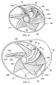
- a fuel injector 44 according to the present disclosure is shown more clearly in figures 3 to 6 .
- the fuel injector 44 comprises a fuel feed arm 46 and a fuel injector head 48.
- the fuel feed arm 46 has a first internal fuel passage 50 for the supply of pilot fuel to the fuel injector head 48 and a second internal fuel passage 52 for the supply of main fuel to the fuel injector head 48.
- the fuel injector head 48 has an axis Y and the fuel feed arm 46 extends generally radially with respect to the axis Y of the fuel injector head 48 and also generally radially with respect to the axis 11 of the turbofan gas turbine engine 10.
- the axis Y of each fuel injector head 48 is generally aligned with the axis of the corresponding aperture 38 in the upstream end wall 36 of the combustion chamber 15.
- the fuel injector 44 comprises a pilot fuel injector 60, a main fuel injector 72, a plurality of air swirlers 58, 68, 70 and 76 and a shroud 66, wherein the shroud 66 is arranged around the pilot fuel injector 60, the main fuel injector 72 and the plurality of air swirlers 58, 68, 70 and 76.
- the shroud 66 has a radially inner surface 67 and the radially inner surface 67 of the shroud 66 is generally circular in cross-section in a plane perpendicular to the axis Y of the fuel injector head 48 at the downstream end of the shroud 66.
- the radially inner surface 67 of the shroud 66 is generally non-circular in cross-section in a plane perpendicular to the axis Y of the fuel injector head 48 at the upstream end of the shroud 66 and has different dimensions in two mutually perpendicular directions.
- a central member 54 is arranged on the axis Y of the fuel injector head 48.
- a first member 56 is arranged coaxially around the central member 54 and a first air swirler 58 is arranged radially between the central member 54 and the first member 56.
- the first air swirler 58 comprises a plurality of circumferentially, angularly, spaced vanes 59 extending radially from the central member 54 to the first member 56.
- the vanes 59 interconnect the central member 54 and the first member 56.
- a pilot fuel injector 60 is arranged to supply fuel into a passage at least defined by the first member 56, e.g. by an inner surface 62 of the first member 56.
- the pilot fuel injector 60 is arranged within the first member 56 to supply fuel onto the inner surface 62 of the first member 56.
- a second member 64 is arranged coaxially between a downstream portion 56C of the first member 56 and a downstream portion 66C of the shroud 66.
- a second air swirler 68 is arranged radially between an upstream portion 56A of the first member 56 and an upstream portion 66A of the shroud 66 and between a downstream portion 56C of the first member 56 and an upstream portion 64A of the second member 64.
- a third air swirler 70 is arranged in an annular passage 78 between the downstream portion 66C of the shroud 66 and the second member 64.
- the third air swirler 70 comprises a plurality of circumferentially, angularly, spaced vanes 71 extending radially from the second member 64 to the shroud 66.
- the vanes 71 interconnect the second member 64 and the shroud 66.
- the main fuel injector 72 is arranged to supply fuel into an annular passage 74 between the downstream portion 56C of the first member 56 and the second member 64 and a fourth air swirler 76 extends through the first member 56.
- the radially inner surface 67 of the shroud 66 is generally elliptical, oval, kidney shaped, oblong or rectangular in cross-section in a plane perpendicular to the axis Y of the fuel injector head 48 at the upstream end of the shroud 66.
- the radially inner surface 67 of the shroud 66 changes from being circular in cross-section in a plane perpendicular to the axis Y of the fuel injector head 48 at the downstream end of the shroud 66 to being generally non-circular in cross-section in a plane perpendicular to the axis Y of the fuel injector head 48 at the upstream end of the shroud 66.
- the radially inner surface 67 of the shroud 66 is generally circular in cross-section in a plane perpendicular to the axis Y of the fuel injector head 48 at an inlet to the annular passage 78 formed between the second member 64 and the downstream portion 66C of the shroud 66.
- the radially inner surface 67 of the shroud 66 changes from being circular in cross-section in a plane perpendicular to the axis Y of the fuel injector head 48 at the inlet to the annular passage 78 formed between the second member 64 and the downstream portion 66C of the shroud 66 to being generally non-circular in cross-section in a plane perpendicular to the axis Y of the fuel injector head 48 at the upstream portion 66A of the shroud 66.
- the upstream end of the shroud 66 and the upstream end of the first member 56 are arranged in a common plane perpendicular to the axis Y of the fuel injector head 48.
- the upstream end of the shroud 66 and the upstream end of the first member 56 may be arranged in axially spaced planes perpendicular to the axis of the fuel injector 48, for example the upstream end of the shroud 66 may be arranged in a plane upstream of the upstream end of the first member 56 or the upstream end of the first member 56 may be upstream of the upstream end of the shroud 66.
- the second air swirler 68 comprises a plurality of circumferentially, angularly, spaced vanes 69 extending radially from the first member 56 to the shroud 66 and from the first member 56 to the second member 64.
- the vanes 69 interconnect the first member 56 and the shroud 66 and interconnect the first member 56 and the second member 64.
- Each vane 69 has a leading edge 69A, a trailing edge 69B, a pressure surface 69C extending from the leading edge 69A to the trailing edge 69B and a suction surface 69D extending from the leading edge 69A to the trailing edge 69B.
- the vanes 69 extend axially from adjacent the upstream ends of the shroud 66 and the first member 56 to a position upstream of the main fuel injector 72, e.g. from the upstream ends of the shroud 66 and the first member 56 or from a position downstream of the upstream ends of the shroud 66 and the first member 56.
- the leading edges 69A of each vane 69 are positioned at or axially downstream of the upstream ends of the shroud 66 and the first member 56.
- the trailing edges 69B of the vanes 69 are positioned axially between the upstream and downstream ends of the second member 64.
- vanes 69 There is a relatively small number of vanes 69 and the vanes 69 have a relatively long chord length and are relatively thick compared to the prior art vanes. In this example there are six vanes 69, but other suitable number of vanes 69 may be used, e.g. four, five, seven or eight.
- the radially outer ends 69I of the vanes 69 are circumferentially, angularly, displaced, or leant, relative to the radially inner ends 69J of the vanes 69.
- each of the vanes 69 has a first, upstream, portion 69F and a second, downstream, portion 69G and the first portion 69F extends radially between the first member 56 and the shroud 66 and the second portion 69G extends radially between the first member 56 and the second member 64.
- the upstream portion 69F of each of the vanes 69 extends radially between the upstream portion 56A of the first member 56 and the upstream portion 66A of the shroud 66 and the downstream portion 69G of each of the vanes 69 extends radially between the downstream portion 56C of the first member 56 and the second member 64.
- the upstream portion 56A of the first member 56 extends in an upstream direction from a plane perpendicular to the axis Y of the fuel injector 44 at the upstream end of the second member 64 and the downstream portion 56C of the first member 56 extends in a downstream direction from the plane perpendicular to the axis Y of the fuel injector 44 at the upstream end of the second member 64.
- One of the vanes 69 has a first passage 50A extending radially there-through to supply fuel to the pilot fuel injector 62.
- One of the vanes 69 has a second passage 52A extending there-through to supply fuel to the main fuel injector 72.
- the passages 50A and 52A may be in the same vane 69 or the passages 50A and 52A may be in different vanes 69.
- the main fuel injector 72 is arranged to supply fuel onto the inner surface 65 of the second member 64.
- each of the vanes 69 has a second passage 52A extending there-through to supply fuel to the main fuel injector 72.
- each of the vanes 69 has apertures 69E in the pressure surface of the vane 69 to supply fuel into the annular passage 74 between the first member 56 and the second member 64 and to act as the main fuel injector 72.
- the fourth air swirler 76 comprises a plurality of ports, or passages, 80 extending through the first member 56.
- the ports 80 have inlets arranged tangentially to the radially outer surface 56D of the first member 56 and the ports 80 extend with axial and circumferential components through the first member 56.
- the radially outer surface 56D of the first member 56 is generally circular in cross-section in a plane perpendicular to the axis Y of the fuel injector head 48.
- the diameter of the radially outer surface 56D of the first member 56 increases from the upstream end to the downstream end of the first member 56.
- the diameter of the radially inner surface 67 of the shroud 66 decreases from the upstream end of the shroud 66 to the inlet to the annular passage 78 formed between the second member 64 and the downstream end of the shroud.
- the diameter of the radially inner surface 67 of the shroud 66 increases from the inlet of the annular passage 78 to a predetermined diameter.
- the radially inner surface 67 of the shroud 66 comprise a cylindrical surface 67A at the predetermined diameter.
- the radially inner surface 67 of the shroud 66 decreases in diameter from the predetermined diameter to a nose 67B and then increases in diameter from the nose 67B to the downstream end of the shroud 66.
- the radially inner surface of the second member 64 decreases in diameter from the inlet of the annular passage 78 at the upstream end of the second member 64 to a minimum diameter and then increases in diameter from the minimum diameter to the downstream end of the second member 64.
- the radially outer surface of the second member 64 increases in diameter from the inlet of the annular passage 78 at the upstream end of the second member 64 to a maximum diameter.
- the radially outer surface of the second member 64 has a cylindrical portion at the maximum diameter. The radially outer surface of the second member 64 decreases in diameter from the cylindrical portion to the downstream end of the second member 64.
- the downstream end of the second member 64 and the nose 67B of the shroud 66 are arranged in a common plane perpendicular to the axis Y of the fuel injector head 48.
- the downstream end of the first member 56 and the downstream end of the second member 64 are arranged in a common plane perpendicular to the axis Y of the fuel injector head 48.
- the downstream end of the second member 64 and the nose 67B of the shroud 66 may be arranged in axially spaced planes perpendicular to the axis of the fuel injector 48, for example the downstream end of the second member 66 may be arranged in a plane upstream of the nose 67B of the shroud 66 or the nose 67B of the shroud 66 may be upstream of the downstream end of the second member 64.
- the downstream end of the first member 56 and the downstream end of the second member 64 may be arranged in axially spaced planes perpendicular to the axis of the fuel injector 48, for example the downstream end of the first member 56 may be arranged in a plane upstream of the downstream end of the second member 64 or the downstream end of the second member 64 may be upstream of the downstream end of the first member 66.
- the central member 54 is arranged radially within the upstream portion 56A of the first member 56.
- the radially inner surface 56E of the first member 56 has a first diameter at an upstream portion 56F of the radially inner surface of the first member 56, a second minimum diameter at an intermediate portion 56G of the radially inner surface of the first member 56.
- the first member 56 has a radially extending surface 56I.
- the ports, or passages, 80 of the fourth air swirler 76 extend through the first member 56 from the radially outer surface 56D to the radially extending surface 56I.
- the radially inner surface 56E of the downstream portion 56H of the first member 56 increases in diameter from the intermediate portion 56G to the downstream end of the first member 56.
- the relatively long and relatively thick vanes of the second air swirler 68 approximately maintain the space to chord ratio of existing fuel injectors in order to provide the same degree of swirl to the air flowing there-through.
- the vanes of the second air swirler 68 are designed to provide the same degree of swirl as a conventional design.
- the vanes of the second air swirler 68 have a low hub to tip radius ratio and so the space to chord ratio may vary.
- the annular passage 74 extends the full length axial length of the fuel injector head 48.
- the annular passage 74 has an upstream portion 74A defined radially between the upstream portion 56A of the first member 56 and the upstream portion 66A of the shroud 66 and a downstream portion 74B defined radially between the downstream portion 56C of the first member 56 and the second member 64.
- the annular passage 74 forms the main inner swirler passage for the main fuel injector 72 and the annular passage 78 forms the main outer swirler passage for the main fuel injector 72. It is seen that the air for the main outer swirler passage, annular passage 78, is ducted off, part of the way along the main inner swirler passage, annular passage 74.
- the radially inner surface 65 of the second member 64 is generally circular in cross-section in a plane perpendicular to the axis Y of the fuel injector from a position upstream of the position of the main fuel injector 72 to the downstream end of the second member 64.
- the remainder of the radially inner surface 65 of the second member 64 to the upstream end of the second member 64 may be circular in cross-section in a plane perpendicular to the axis Y of the fuel injector.
- the radially inner surface 65 of the second member 64 at the upstream end of the second member 64 may be elliptical in cross-section in a plane perpendicular to the axis Y of the fuel injector and the radially inner surface 65 of the second member 64 transitions to a circular cross-section in a plane perpendicular to the axis Y of the fuel injector to the position upstream of the main fuel injector 72.
- the radially inner surface 65 of the second member 64 is generally circular in cross-section in a plane perpendicular to the axis Y of the fuel injector at the downstream of the trailing edges 69B of the vanes 69 of the second air swirler 68.
- the radially inner surface 65 of the second member 64 is generally circular from a position upstream of the trailing edges 69B of the vanes 69 of the second air swirler 68 and upstream of the position of the main fuel injector 72.
- the radially inner surface 67 of the shroud 66 may be circular in cross-section in a plane perpendicular to the axis Y of the fuel injector at the inlet to the annular passage 78 and throughout the full length of the annular passage 78 to the downstream end of the shroud 66 and the radially outer surface of the second member 64 may be circular in cross-section in a plane perpendicular to the axis Y of the fuel injector throughout the full length of the annular passage 78 from the upstream end to the downstream end of the second member 64.
- radially inner surface 67 of the shroud 66 may be circular in cross-section in a plane perpendicular to the axis Y of the fuel injector for a downstream portion of the annular passage 78 to the downstream end of the shroud 66 and the radially outer surface of the second member 64 may be circular in cross-section in a plane perpendicular to the axis Y of the fuel injector for the downstream portion of the annular passage 78 to the downstream end of the second member 64.
- the passage extending coaxially through the first member forms the pilot inner swirler passage for the pilot fuel injector 62 and the ports 80 through the first member 56 from the pilot outer swirler passage for the pilot fuel injector 62. It is seen that the air for the pilot outer swirler passage is ducted off, part of the way along the main inner swirler passage, annular passage 74.
- the cross-sectional area of the main inner swirler passage 74 defined between the elliptical radially inner surface of the shroud 66 in cross-section in a plane perpendicular to the axis Y of the fuel injector head 48 and the radially outer surface 56D of the second member 56 at the upstream end of the shroud 66 is significantly larger than the cross-sectional areas of the annular passages 74 and 78 in a plane perpendicular to the axis Y of the fuel injector head 48 at the downstream end of the shroud 66.
- pilot fuel is supplied through the pilot fuel passages 50 and 50A to the pilot fuel injector 62 in the first member 56.
- the pilot fuel is supplied onto the intermediate portion 56G of the radially inner surface 56E of the first member 56 to form a film of pilot fuel.
- Air is supplied through the first air swirler 58 and the fourth air swirler 76 to atomise the pilot fuel which is then supplied into the combustion chamber 16.
- the main fuel injector 72 is in use the main fuel is supplied through the main fuel passages 52 and 52A to the main fuel injector 72.
- the main fuel is supplied onto the radially inner surface 65 of the second member 64 to form a film of main fuel.
- Air is supplied through the second air swirler 68 and the third air swirler 70 to atomise the main fuel which is then supplied into the combustion chamber 16.
- the air flow in the second air swirler 68, the third air swirler 70 and the fourth air swirler 76 are all swirled in the same direction.
- the air flow through the first air swirler 58 may be arranged to swirl in the same direction or the opposite direction to the air flow through the second, third and fourth air swirlers 68, 70 and 76.
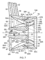
- a further fuel injector 144 according to the present disclosure is shown more clearly in figures 7 and 8 .
- the fuel injector 144 is substantially the same as the fuel injector 44 shown in Figures 3 to 6 and like parts ae denoted by like numerals.
- the second air swirler 68 again comprises a plurality of circumferentially, angularly, spaced vanes 69 extending radially from the first member 56 to the shroud 66 and from the first member 56 to the second member 64.
- Each vane 69 has a leading edge 69A, a trailing edge 69B, a pressure surface 69C extending from the leading edge 69A to the trailing edge 69B and a suction surface 69D extending from the leading edge 69A to the trailing edge 69B.
- the vanes 69 extend axially from the upstream ends of the shroud 66 and first member 56 to a position upstream of the main fuel injector 72.
- the radially outer ends 69I of the vanes 69 are circumferentially displaced relative to the radially inner ends 69J of the vanes 69.
- each of the vanes 69 of the second air swirler 68 has a third portion 69H which extends into the annular passage 78 to form the vanes of the third air swirler 70, as seen more clearly in Figure 8 .
- each of the long chord length vanes 69 has a first, upstream, portion 69F, a second, downstream, portion 69G and a third portion 69H.
- the air flow in the second air swirler 68, the third air swirler 70 and the fourth air swirler 76 are all swirled in the same direction.
- the air flow through the first air swirler 58 may be arranged to swirl in the same direction or the opposite direction to the air flow through the second, third and fourth air swirlers 68, 70 and 76.
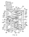
- the fuel injector 244 is substantially the same as the fuel injector 44 shown in Figures 3 to 6 and like parts ae denoted by like numerals.
- the fuel injector 244 differs in that although the first member 256 comprises an upstream portion 256A and a downstream portion 256C, the first member 256 has an annular passage 279.
- the annular passage 279 axially and radially separates the first member 256 into an inner portion 255 and an outer portion 257.
- the inner portion 255 has an extension extending coaxially through the outer portion 257 and the inner portion 255 has the pilot fuel injector 62 and the first fuel passage 50A.
- the fourth air swirler 276 is provided in the annular passage 279 and the fourth air swirler 276 comprises a plurality of circumferentially, angularly, spaced vanes which extend radially between and interconnect the inner portion 255 and the outer portion 257 of the first member 256.
- the downstream end of the inner portion 255 has a conical outer surface and the outer portion 257 has a conical member 281 at the same axial position as the conical outer surface of the inner portion 255 to direct the air flow radially inwardly towards the axis Y.
- the air flow in the second air swirler 68 and the third air swirler 70 are swirled in the same direction.
- the air flow through the fourth air swirler 276 may be arranged to swirl in the same direction or the opposite direction to the air flow through the second and third air swirlers 68 and 70.
- the air flow through the first air swirler 58 may be arranged to swirl in the same direction or the opposite direction to the air flow through the fourth air swirler 276.
- each of the vanes 69 of the second air swirler 68 has a third portion 69H which extends into the annular passage 78 to form the vanes of the third air swirler 70, as seen more clearly in Figure 10 .
- each of the long chord length vanes 69 has a first, upstream, portion 69F, a second, downstream, portion 69G and a third portion 69H.
- the air flow in the second air swirler 68 and the third air swirler 70 are swirled in the same direction.
- the air flow through the fourth air swirler 276 may be arranged to swirl in the same direction or the opposite direction to the air flow through the second and third air swirlers 68 and 70.
- the air flow through the first air swirler 58 may be arranged to swirl in the same direction or the opposite direction to the air flow through the fourth air swirler 276.
- the number of thick, long chord vanes of the second air swirler may be varied and the length of the long chord vanes is varied accordingly in order to maintain the space to chord ratio. If the number of long chord vanes of the second air swirler is increased by one, then the length of the long chord vanes may be decreased to maintain the space to chord ratio and conversely if the number of long chord vanes of the second air swirler is reduced by one, then the length of the long chord vanes may be increased to maintain the space to chord ratio.
- the axial position of the leading edges of the long chord vanes may vary with the number and length of the long chord vanes of the second air swirler.
- trailing edges of the long chord vanes of the second air swirler are generally positioned upstream, axially upstream, of the main fuel injector for embodiments where the main fuel injector is positioned in the second member.
- the trailing edges of the long chord vanes of the second air swirler are positioned downstream, axially downstream, of the main fuel injector for embodiments where the main fuel injector is positioned in the vanes of the second air swirler.
- the trailing edges of the long chord vanes remains may remain at a fixed axial position.
- the radially inner surface of the shroud changes from a generally elliptical cross-section in a plane perpendicular to the axis of the fuel injector at the upstream end of the shroud to a generally circular cross-section in a plane perpendicular to the axis of the fuel injector at the downstream end of the shroud.
- the axial position at which the radially inner surface of the shroud has changed to a generally circular cross-section may vary and the exact axial position is determined to minimise pressure gradients in the fuel injector.
- the advantages of a fuel injector according to the present disclosure are that the long chord vanes of the second air swirler may be relatively thick, without creating excessive blockage, and thus the leading edges of the vanes may be made insensitive, or less sensitive, to the approach angle of the air and hence improve the off design performance of the fuel injector. Due to the use of longer, thicker and fewer vanes for the second air swirler the vanes are easier to manufacture and there is a reduction in parts count for the fuel injector. Due to the fact that the vanes of the second air swirler are thicker it is possible to provide a fuel passage from the fuel feed arm to the pilot fuel injector within a vane and hence to eliminate a main stem to the pilot fuel injector used in the prior art.
- vanes of the second air swirler are thicker it is possible to provide fuel passages in the vanes of the second air swirler from the fuel feed arm and to effuse fuel from apertures in the pressure surfaces of the vanes to act as the main fuel injector and this dispenses with the need for a separate fuel pre-filming surface.
- the use of apertures in the pressure surfaces of the vanes to act as the main fuel injector also improves the fuel injector performance by using the parasitic vane frictional losses advantageous, i.e. by using the shear force to spread and atomise the main fuel. Hence the parasitic total pressure losses are minimised.
- the use of apertures in the pressure surface of the vanes lengthens the time scale for evaporation and mixing of the main fuel which may improve the relight and smoke emission characteristics of the fuel injector.
- the air entering the main outer swirler passage is co-swirling, swirling in the same direction, with the air flowing through the main inner swirler passage.
- the advantage of this is that the air flowing through the main outer swirler passage may be used to control the vane secondary flow development and hence prevent separation of the airflow from the vanes.
- the air entering the main outer swirler passage is pre-swirled and hence the amount of swirling to be provided by the air swirler in the main outer swirler passage is reduced and hence fewer vanes are required or the same number and type of vanes may be used to provide additional swirling.
- the use of the ports for the pilot outer swirler passage eliminates the need for small swirl vane geometries and hence simplifies the fuel injector arrangement.
- the use of a few, thick, long chord vanes for the air swirler in the main inner swirler passage enable the fuel injector to simultaneously reduce the total pressure loss, improve reaction zone homogeneity and make the fuel injector less sensitive to the approaching air flow conditions.
- the thick, long chord vanes have thicker leading edges which makes them less sensitive to the approaching air flow conditions.
- the elliptical radially inner surface of the shroud in cross-section in a plane perpendicular to the axis of the fuel injector head at the upstream end of the shroud provides a more uniform flow of air into the fuel injector, better mixing of the fuel and air and hence lower emissions.
- the radially inner surface of the shroud is generally circular in cross-section in a plane perpendicular to the axis of the fuel injector at the trailing edges of the vanes of the second air swirler.
- the radially inner and outer surfaces of the second member are generally circular in cross-section in a plane perpendicular to the axis of the fuel injector at the trailing edges of the vanes of the second air swirler.
- the radially outer surface of the first member is generally circular in cross-section in a plane perpendicular to the axis of the fuel injector at the trailing edges of the vanes of the second air swirler.
- the fourth air swirler either comprises a plurality of passages extending though the first member and each passage extends with axial, radial and tangential components or comprises an annular passage extending through the first member and the annular passage has a plurality of swirl vanes.
- the present disclosure has referred to the radially inner surface of the shroud being generally non-circular in cross-section in a plane perpendicular to the axis of the fuel injector at the upstream end of the shroud and has different dimensions in two mutually perpendicular directions, it may be possible to provide the radially inner surface of the shroud such that it is generally circular in cross-section in a plane perpendicular to the axis of the fuel injector at the upstream end of the shroud and in such circumstances the radially inner surface of the shroud being generally circular in cross-section in a plane perpendicular to the axis of the fuel injector from the upstream end to the downstream end of the fuel injector.
- This arrangement also produces an axial acceleration in the flow through the fuel injector head which helps to aerodynamically off-load the turning vanes.
- turbofan gas turbine engine the present disclosure is equally applicable to a turbojet gas turbine engine, a turbo-shaft gas turbine engine or a turbo-propeller gas turbine engine.
- aero gas turbine engine the present disclosure is equally applicable to a marine gas turbine engine, an industrial gas turbine engine or an automotive gas turbine engine.
Landscapes
- Engineering & Computer Science (AREA)
- Chemical & Material Sciences (AREA)
- Combustion & Propulsion (AREA)
- Mechanical Engineering (AREA)
- General Engineering & Computer Science (AREA)
- Fuel-Injection Apparatus (AREA)
Applications Claiming Priority (1)
| Application Number | Priority Date | Filing Date | Title |
|---|---|---|---|
| GBGB1516977.4A GB201516977D0 (en) | 2015-09-25 | 2015-09-25 | A Fuel Injector For A Gas Turbine Engine Combustion Chamber |
Publications (2)
| Publication Number | Publication Date |
|---|---|
| EP3147571A1 true EP3147571A1 (de) | 2017-03-29 |
| EP3147571B1 EP3147571B1 (de) | 2020-05-13 |
Family
ID=54544105
Family Applications (1)
| Application Number | Title | Priority Date | Filing Date |
|---|---|---|---|
| EP16185750.3A Active EP3147571B1 (de) | 2015-09-25 | 2016-08-25 | Kraftstoffeinspritzdüse für eine gasturbinenbrennkammer |
Country Status (3)
| Country | Link |
|---|---|
| US (1) | US10295188B2 (de) |
| EP (1) | EP3147571B1 (de) |
| GB (1) | GB201516977D0 (de) |
Cited By (4)
| Publication number | Priority date | Publication date | Assignee | Title |
|---|---|---|---|---|
| EP3404331A1 (de) * | 2017-05-18 | 2018-11-21 | United Technologies Corporation | Brennstoffluftmischeranordnung für eine gasturbinenbrennkammer |
| EP4467878A1 (de) * | 2023-05-23 | 2024-11-27 | Rolls-Royce plc | Verbesserte brennkammervorrichtung |
| US12326257B2 (en) | 2023-05-23 | 2025-06-10 | Rolls-Royce Plc | Combustor apparatus |
| EP4667825A1 (de) * | 2024-06-20 | 2025-12-24 | General Electric Company | Gasturbinentriebwerk und brennstoffdüsenanordnung dafür |
Families Citing this family (11)
| Publication number | Priority date | Publication date | Assignee | Title |
|---|---|---|---|---|
| EP3225915B1 (de) * | 2016-03-31 | 2019-02-06 | Rolls-Royce plc | Brenstoffinjektor und verfahren zur herstellung |
| US11149952B2 (en) * | 2016-12-07 | 2021-10-19 | Raytheon Technologies Corporation | Main mixer in an axial staged combustor for a gas turbine engine |
| US10816208B2 (en) * | 2017-01-20 | 2020-10-27 | General Electric Company | Fuel injectors and methods of fabricating same |
| EP3425281B1 (de) * | 2017-07-04 | 2020-09-02 | General Electric Company | Pilotdüse mit inline-vormischung |
| US11162682B2 (en) * | 2019-10-11 | 2021-11-02 | Solar Turbines Incorporated | Fuel injector |
| US11506388B1 (en) * | 2021-05-07 | 2022-11-22 | General Electric Company | Furcating pilot pre-mixer for main mini-mixer array in a gas turbine engine |
| US12454909B2 (en) | 2021-12-03 | 2025-10-28 | General Electric Company | Combustor size rating for a gas turbine engine using hydrogen fuel |
| US12092332B2 (en) | 2021-12-29 | 2024-09-17 | General Electric Company | Fuel nozzle and swirler |
| US12331932B2 (en) * | 2022-01-31 | 2025-06-17 | General Electric Company | Turbine engine fuel mixer |
| KR102667812B1 (ko) * | 2022-02-07 | 2024-05-20 | 두산에너빌리티 주식회사 | 연소기용 노즐 및 이를 포함하는 가스 터빈 |
| DE102024202602A1 (de) * | 2024-03-19 | 2025-09-25 | Rolls-Royce Deutschland Ltd & Co Kg | Injektoranordnung für eine Gasturbine und Flugzeug |
Citations (3)
| Publication number | Priority date | Publication date | Assignee | Title |
|---|---|---|---|---|
| US20120047903A1 (en) * | 2008-05-06 | 2012-03-01 | Delavan Inc. | Staged pilots in pure airblast injectors for gas turbine engines |
| EP2703720A2 (de) * | 2012-08-28 | 2014-03-05 | Rolls-Royce Deutschland Ltd & Co KG | Verfahren zum Betrieb eines Magervormischbrenners einer Fluggasturbine sowie Vorrichtung zur Durchführung des Verfahrens |
| US20140157781A1 (en) * | 2012-12-12 | 2014-06-12 | Rolls-Royce Plc | Fuel injector and a gas turbine engine combustion chamber |
Family Cites Families (10)
| Publication number | Priority date | Publication date | Assignee | Title |
|---|---|---|---|---|
| JP3903195B2 (ja) | 2003-12-16 | 2007-04-11 | 川崎重工業株式会社 | 燃料ノズル |
| GB2439097B (en) | 2006-06-15 | 2008-10-29 | Rolls Royce Plc | Fuel injector |
| US8661779B2 (en) * | 2008-09-26 | 2014-03-04 | Siemens Energy, Inc. | Flex-fuel injector for gas turbines |
| US9513009B2 (en) | 2009-02-18 | 2016-12-06 | Rolls-Royce Plc | Fuel nozzle having aerodynamically shaped helical turning vanes |
| JP5472863B2 (ja) | 2009-06-03 | 2014-04-16 | 独立行政法人 宇宙航空研究開発機構 | ステージング型燃料ノズル |
| US9429074B2 (en) | 2009-07-10 | 2016-08-30 | Rolls-Royce Plc | Aerodynamic swept vanes for fuel injectors |
| EP2743857A1 (de) | 2012-12-13 | 2014-06-18 | Gemalto SA | Verfahren zur Ermöglichung einer sicheren Sitzung zwischen einer Vorrichtung und eines Servers |
| GB201303428D0 (en) | 2013-02-27 | 2013-04-10 | Rolls Royce Plc | A vane structure and a method of manufacturing a vane structure |
| GB201317241D0 (en) | 2013-09-30 | 2013-11-13 | Rolls Royce Plc | Airblast Fuel Injector |
| CN104406196B (zh) | 2014-11-10 | 2016-05-25 | 中国科学院工程热物理研究所 | 一种双级预膜分层部分预混高温升燃烧室结构 |
-
2015
- 2015-09-25 GB GBGB1516977.4A patent/GB201516977D0/en not_active Ceased
-
2016
- 2016-08-25 EP EP16185750.3A patent/EP3147571B1/de active Active
- 2016-08-25 US US15/247,340 patent/US10295188B2/en active Active
Patent Citations (3)
| Publication number | Priority date | Publication date | Assignee | Title |
|---|---|---|---|---|
| US20120047903A1 (en) * | 2008-05-06 | 2012-03-01 | Delavan Inc. | Staged pilots in pure airblast injectors for gas turbine engines |
| EP2703720A2 (de) * | 2012-08-28 | 2014-03-05 | Rolls-Royce Deutschland Ltd & Co KG | Verfahren zum Betrieb eines Magervormischbrenners einer Fluggasturbine sowie Vorrichtung zur Durchführung des Verfahrens |
| US20140157781A1 (en) * | 2012-12-12 | 2014-06-12 | Rolls-Royce Plc | Fuel injector and a gas turbine engine combustion chamber |
Cited By (6)
| Publication number | Priority date | Publication date | Assignee | Title |
|---|---|---|---|---|
| EP3404331A1 (de) * | 2017-05-18 | 2018-11-21 | United Technologies Corporation | Brennstoffluftmischeranordnung für eine gasturbinenbrennkammer |
| EP4467878A1 (de) * | 2023-05-23 | 2024-11-27 | Rolls-Royce plc | Verbesserte brennkammervorrichtung |
| US12228283B2 (en) | 2023-05-23 | 2025-02-18 | Rolls-Royce Plc | Combustor apparatus |
| GB2633884A (en) * | 2023-05-23 | 2025-03-26 | Rolls Royce Plc | An improved combustor apparatus |
| US12326257B2 (en) | 2023-05-23 | 2025-06-10 | Rolls-Royce Plc | Combustor apparatus |
| EP4667825A1 (de) * | 2024-06-20 | 2025-12-24 | General Electric Company | Gasturbinentriebwerk und brennstoffdüsenanordnung dafür |
Also Published As
| Publication number | Publication date |
|---|---|
| US20170089582A1 (en) | 2017-03-30 |
| EP3147571B1 (de) | 2020-05-13 |
| GB201516977D0 (en) | 2015-11-11 |
| US10295188B2 (en) | 2019-05-21 |
Similar Documents
| Publication | Publication Date | Title |
|---|---|---|
| EP3147571B1 (de) | Kraftstoffeinspritzdüse für eine gasturbinenbrennkammer | |
| US12492819B2 (en) | Gas turbine engine fuel nozzle having a secondary fuel passage through a swirler | |
| EP2578941A2 (de) | System zur Brennstoffeinspritzung in eine Brennstoffdüse | |
| CN115218213B (zh) | 燃烧器旋流轮叶设备 | |
| US11635209B2 (en) | Gas turbine combustor dome with integrated flare swirler | |
| US12092324B2 (en) | Flare cone for a mixer assembly of a gas turbine combustor | |
| CA3018441A1 (en) | Swirler for mixing fuel with air in a combustion engine | |
| US11592182B1 (en) | Swirler ferrule plate having pressure drop purge passages | |
| US20180058696A1 (en) | Fuel-air mixer assembly for use in a combustor of a turbine engine | |
| US20230266002A1 (en) | Coupling a fuel nozzle purge flow directly to a swirler | |
| EP2905535A1 (de) | Verbrennungsanlage | |
| CN115218212B (zh) | 燃烧器旋流轮叶设备 | |
| US11994295B2 (en) | Multi pressure drop swirler ferrule plate | |
| US10823418B2 (en) | Gas turbine engine combustor comprising air inlet tubes arranged around the combustor | |
| CN110345512B (zh) | 燃气涡轮发动机 | |
| CN112303663A (zh) | 涡轮发动机的包括由柱在内部界定的旋流室的喷射器头部 | |
| JP7689839B2 (ja) | 改良されたスワーラベーン構造を有する燃料ノズル | |
| EP4517172A2 (de) | Brennstoffdüse und drallerzeuger | |
| US11566789B1 (en) | Ferrule for fuel-air mixer assembly | |
| US20250327570A1 (en) | Fuel injector for a turbine engine | |
| US12078349B2 (en) | Combustion system | |
| EP4321805A1 (de) | Kraftstoffeinspritzer |
Legal Events
| Date | Code | Title | Description |
|---|---|---|---|
| PUAI | Public reference made under article 153(3) epc to a published international application that has entered the european phase |
Free format text: ORIGINAL CODE: 0009012 |
|
| STAA | Information on the status of an ep patent application or granted ep patent |
Free format text: STATUS: THE APPLICATION HAS BEEN PUBLISHED |
|
| AK | Designated contracting states |
Kind code of ref document: A1 Designated state(s): AL AT BE BG CH CY CZ DE DK EE ES FI FR GB GR HR HU IE IS IT LI LT LU LV MC MK MT NL NO PL PT RO RS SE SI SK SM TR |
|
| AX | Request for extension of the european patent |
Extension state: BA ME |
|
| STAA | Information on the status of an ep patent application or granted ep patent |
Free format text: STATUS: REQUEST FOR EXAMINATION WAS MADE |
|
| 17P | Request for examination filed |
Effective date: 20170710 |
|
| RBV | Designated contracting states (corrected) |
Designated state(s): AL AT BE BG CH CY CZ DE DK EE ES FI FR GB GR HR HU IE IS IT LI LT LU LV MC MK MT NL NO PL PT RO RS SE SI SK SM TR |
|
| RAP1 | Party data changed (applicant data changed or rights of an application transferred) |
Owner name: ROLLS-ROYCE PLC |
|
| GRAP | Despatch of communication of intention to grant a patent |
Free format text: ORIGINAL CODE: EPIDOSNIGR1 |
|
| STAA | Information on the status of an ep patent application or granted ep patent |
Free format text: STATUS: GRANT OF PATENT IS INTENDED |
|
| GRAS | Grant fee paid |
Free format text: ORIGINAL CODE: EPIDOSNIGR3 |
|
| GRAA | (expected) grant |
Free format text: ORIGINAL CODE: 0009210 |
|
| STAA | Information on the status of an ep patent application or granted ep patent |
Free format text: STATUS: THE PATENT HAS BEEN GRANTED |
|
| INTG | Intention to grant announced |
Effective date: 20200316 |
|
| AK | Designated contracting states |
Kind code of ref document: B1 Designated state(s): AL AT BE BG CH CY CZ DE DK EE ES FI FR GB GR HR HU IE IS IT LI LT LU LV MC MK MT NL NO PL PT RO RS SE SI SK SM TR |
|
| REG | Reference to a national code |
Ref country code: GB Ref legal event code: FG4D |
|
| REG | Reference to a national code |
Ref country code: CH Ref legal event code: EP |
|
| REG | Reference to a national code |
Ref country code: DE Ref legal event code: R096 Ref document number: 602016036275 Country of ref document: DE |
|
| REG | Reference to a national code |
Ref country code: AT Ref legal event code: REF Ref document number: 1270787 Country of ref document: AT Kind code of ref document: T Effective date: 20200615 |
|
| REG | Reference to a national code |
Ref country code: LT Ref legal event code: MG4D |
|
| REG | Reference to a national code |
Ref country code: NL Ref legal event code: MP Effective date: 20200513 |
|
| PG25 | Lapsed in a contracting state [announced via postgrant information from national office to epo] |
Ref country code: SE Free format text: LAPSE BECAUSE OF FAILURE TO SUBMIT A TRANSLATION OF THE DESCRIPTION OR TO PAY THE FEE WITHIN THE PRESCRIBED TIME-LIMIT Effective date: 20200513 Ref country code: PT Free format text: LAPSE BECAUSE OF FAILURE TO SUBMIT A TRANSLATION OF THE DESCRIPTION OR TO PAY THE FEE WITHIN THE PRESCRIBED TIME-LIMIT Effective date: 20200914 Ref country code: NO Free format text: LAPSE BECAUSE OF FAILURE TO SUBMIT A TRANSLATION OF THE DESCRIPTION OR TO PAY THE FEE WITHIN THE PRESCRIBED TIME-LIMIT Effective date: 20200813 Ref country code: GR Free format text: LAPSE BECAUSE OF FAILURE TO SUBMIT A TRANSLATION OF THE DESCRIPTION OR TO PAY THE FEE WITHIN THE PRESCRIBED TIME-LIMIT Effective date: 20200814 Ref country code: FI Free format text: LAPSE BECAUSE OF FAILURE TO SUBMIT A TRANSLATION OF THE DESCRIPTION OR TO PAY THE FEE WITHIN THE PRESCRIBED TIME-LIMIT Effective date: 20200513 Ref country code: IS Free format text: LAPSE BECAUSE OF FAILURE TO SUBMIT A TRANSLATION OF THE DESCRIPTION OR TO PAY THE FEE WITHIN THE PRESCRIBED TIME-LIMIT Effective date: 20200913 Ref country code: LT Free format text: LAPSE BECAUSE OF FAILURE TO SUBMIT A TRANSLATION OF THE DESCRIPTION OR TO PAY THE FEE WITHIN THE PRESCRIBED TIME-LIMIT Effective date: 20200513 |
|
| PG25 | Lapsed in a contracting state [announced via postgrant information from national office to epo] |
Ref country code: RS Free format text: LAPSE BECAUSE OF FAILURE TO SUBMIT A TRANSLATION OF THE DESCRIPTION OR TO PAY THE FEE WITHIN THE PRESCRIBED TIME-LIMIT Effective date: 20200513 Ref country code: BG Free format text: LAPSE BECAUSE OF FAILURE TO SUBMIT A TRANSLATION OF THE DESCRIPTION OR TO PAY THE FEE WITHIN THE PRESCRIBED TIME-LIMIT Effective date: 20200813 Ref country code: LV Free format text: LAPSE BECAUSE OF FAILURE TO SUBMIT A TRANSLATION OF THE DESCRIPTION OR TO PAY THE FEE WITHIN THE PRESCRIBED TIME-LIMIT Effective date: 20200513 Ref country code: HR Free format text: LAPSE BECAUSE OF FAILURE TO SUBMIT A TRANSLATION OF THE DESCRIPTION OR TO PAY THE FEE WITHIN THE PRESCRIBED TIME-LIMIT Effective date: 20200513 |
|
| REG | Reference to a national code |
Ref country code: AT Ref legal event code: MK05 Ref document number: 1270787 Country of ref document: AT Kind code of ref document: T Effective date: 20200513 |
|
| PG25 | Lapsed in a contracting state [announced via postgrant information from national office to epo] |
Ref country code: NL Free format text: LAPSE BECAUSE OF FAILURE TO SUBMIT A TRANSLATION OF THE DESCRIPTION OR TO PAY THE FEE WITHIN THE PRESCRIBED TIME-LIMIT Effective date: 20200513 Ref country code: AL Free format text: LAPSE BECAUSE OF FAILURE TO SUBMIT A TRANSLATION OF THE DESCRIPTION OR TO PAY THE FEE WITHIN THE PRESCRIBED TIME-LIMIT Effective date: 20200513 |
|
| PG25 | Lapsed in a contracting state [announced via postgrant information from national office to epo] |
Ref country code: RO Free format text: LAPSE BECAUSE OF FAILURE TO SUBMIT A TRANSLATION OF THE DESCRIPTION OR TO PAY THE FEE WITHIN THE PRESCRIBED TIME-LIMIT Effective date: 20200513 Ref country code: CZ Free format text: LAPSE BECAUSE OF FAILURE TO SUBMIT A TRANSLATION OF THE DESCRIPTION OR TO PAY THE FEE WITHIN THE PRESCRIBED TIME-LIMIT Effective date: 20200513 Ref country code: DK Free format text: LAPSE BECAUSE OF FAILURE TO SUBMIT A TRANSLATION OF THE DESCRIPTION OR TO PAY THE FEE WITHIN THE PRESCRIBED TIME-LIMIT Effective date: 20200513 Ref country code: AT Free format text: LAPSE BECAUSE OF FAILURE TO SUBMIT A TRANSLATION OF THE DESCRIPTION OR TO PAY THE FEE WITHIN THE PRESCRIBED TIME-LIMIT Effective date: 20200513 Ref country code: EE Free format text: LAPSE BECAUSE OF FAILURE TO SUBMIT A TRANSLATION OF THE DESCRIPTION OR TO PAY THE FEE WITHIN THE PRESCRIBED TIME-LIMIT Effective date: 20200513 Ref country code: IT Free format text: LAPSE BECAUSE OF FAILURE TO SUBMIT A TRANSLATION OF THE DESCRIPTION OR TO PAY THE FEE WITHIN THE PRESCRIBED TIME-LIMIT Effective date: 20200513 Ref country code: SM Free format text: LAPSE BECAUSE OF FAILURE TO SUBMIT A TRANSLATION OF THE DESCRIPTION OR TO PAY THE FEE WITHIN THE PRESCRIBED TIME-LIMIT Effective date: 20200513 Ref country code: ES Free format text: LAPSE BECAUSE OF FAILURE TO SUBMIT A TRANSLATION OF THE DESCRIPTION OR TO PAY THE FEE WITHIN THE PRESCRIBED TIME-LIMIT Effective date: 20200513 |
|
| REG | Reference to a national code |
Ref country code: DE Ref legal event code: R097 Ref document number: 602016036275 Country of ref document: DE |
|
| PG25 | Lapsed in a contracting state [announced via postgrant information from national office to epo] |
Ref country code: PL Free format text: LAPSE BECAUSE OF FAILURE TO SUBMIT A TRANSLATION OF THE DESCRIPTION OR TO PAY THE FEE WITHIN THE PRESCRIBED TIME-LIMIT Effective date: 20200513 Ref country code: SK Free format text: LAPSE BECAUSE OF FAILURE TO SUBMIT A TRANSLATION OF THE DESCRIPTION OR TO PAY THE FEE WITHIN THE PRESCRIBED TIME-LIMIT Effective date: 20200513 |
|
| PLBE | No opposition filed within time limit |
Free format text: ORIGINAL CODE: 0009261 |
|
| STAA | Information on the status of an ep patent application or granted ep patent |
Free format text: STATUS: NO OPPOSITION FILED WITHIN TIME LIMIT |
|
| PG25 | Lapsed in a contracting state [announced via postgrant information from national office to epo] |
Ref country code: MC Free format text: LAPSE BECAUSE OF FAILURE TO SUBMIT A TRANSLATION OF THE DESCRIPTION OR TO PAY THE FEE WITHIN THE PRESCRIBED TIME-LIMIT Effective date: 20200513 |
|
| REG | Reference to a national code |
Ref country code: CH Ref legal event code: PL |
|
| 26N | No opposition filed |
Effective date: 20210216 |
|
| PG25 | Lapsed in a contracting state [announced via postgrant information from national office to epo] |
Ref country code: CH Free format text: LAPSE BECAUSE OF NON-PAYMENT OF DUE FEES Effective date: 20200831 Ref country code: LU Free format text: LAPSE BECAUSE OF NON-PAYMENT OF DUE FEES Effective date: 20200825 Ref country code: LI Free format text: LAPSE BECAUSE OF NON-PAYMENT OF DUE FEES Effective date: 20200831 |
|
| REG | Reference to a national code |
Ref country code: BE Ref legal event code: MM Effective date: 20200831 |
|
| PG25 | Lapsed in a contracting state [announced via postgrant information from national office to epo] |
Ref country code: SI Free format text: LAPSE BECAUSE OF FAILURE TO SUBMIT A TRANSLATION OF THE DESCRIPTION OR TO PAY THE FEE WITHIN THE PRESCRIBED TIME-LIMIT Effective date: 20200513 |
|
| PG25 | Lapsed in a contracting state [announced via postgrant information from national office to epo] |
Ref country code: BE Free format text: LAPSE BECAUSE OF NON-PAYMENT OF DUE FEES Effective date: 20200831 Ref country code: IE Free format text: LAPSE BECAUSE OF NON-PAYMENT OF DUE FEES Effective date: 20200825 |
|
| PG25 | Lapsed in a contracting state [announced via postgrant information from national office to epo] |
Ref country code: TR Free format text: LAPSE BECAUSE OF FAILURE TO SUBMIT A TRANSLATION OF THE DESCRIPTION OR TO PAY THE FEE WITHIN THE PRESCRIBED TIME-LIMIT Effective date: 20200513 Ref country code: MT Free format text: LAPSE BECAUSE OF FAILURE TO SUBMIT A TRANSLATION OF THE DESCRIPTION OR TO PAY THE FEE WITHIN THE PRESCRIBED TIME-LIMIT Effective date: 20200513 Ref country code: CY Free format text: LAPSE BECAUSE OF FAILURE TO SUBMIT A TRANSLATION OF THE DESCRIPTION OR TO PAY THE FEE WITHIN THE PRESCRIBED TIME-LIMIT Effective date: 20200513 |
|
| PG25 | Lapsed in a contracting state [announced via postgrant information from national office to epo] |
Ref country code: MK Free format text: LAPSE BECAUSE OF FAILURE TO SUBMIT A TRANSLATION OF THE DESCRIPTION OR TO PAY THE FEE WITHIN THE PRESCRIBED TIME-LIMIT Effective date: 20200513 |
|
| P01 | Opt-out of the competence of the unified patent court (upc) registered |
Effective date: 20230528 |
|
| PGFP | Annual fee paid to national office [announced via postgrant information from national office to epo] |
Ref country code: GB Payment date: 20230822 Year of fee payment: 8 |
|
| PGFP | Annual fee paid to national office [announced via postgrant information from national office to epo] |
Ref country code: FR Payment date: 20230824 Year of fee payment: 8 Ref country code: DE Payment date: 20230828 Year of fee payment: 8 |
|
| REG | Reference to a national code |
Ref country code: DE Ref legal event code: R119 Ref document number: 602016036275 Country of ref document: DE |
|
| GBPC | Gb: european patent ceased through non-payment of renewal fee |
Effective date: 20240825 |
|
| PG25 | Lapsed in a contracting state [announced via postgrant information from national office to epo] |
Ref country code: DE Free format text: LAPSE BECAUSE OF NON-PAYMENT OF DUE FEES Effective date: 20250301 |
|
| PG25 | Lapsed in a contracting state [announced via postgrant information from national office to epo] |
Ref country code: GB Free format text: LAPSE BECAUSE OF NON-PAYMENT OF DUE FEES Effective date: 20240825 |
|
| PG25 | Lapsed in a contracting state [announced via postgrant information from national office to epo] |
Ref country code: FR Free format text: LAPSE BECAUSE OF NON-PAYMENT OF DUE FEES Effective date: 20240831 |