EP3147583B1 - Heisswasserspeicher - Google Patents
Heisswasserspeicher Download PDFInfo
- Publication number
- EP3147583B1 EP3147583B1 EP14892601.7A EP14892601A EP3147583B1 EP 3147583 B1 EP3147583 B1 EP 3147583B1 EP 14892601 A EP14892601 A EP 14892601A EP 3147583 B1 EP3147583 B1 EP 3147583B1
- Authority
- EP
- European Patent Office
- Prior art keywords
- hot water
- flow rate
- water supply
- heat source
- side flow
- Prior art date
- Legal status (The legal status is an assumption and is not a legal conclusion. Google has not performed a legal analysis and makes no representation as to the accuracy of the status listed.)
- Active
Links
Images



Classifications
-
- F—MECHANICAL ENGINEERING; LIGHTING; HEATING; WEAPONS; BLASTING
- F24—HEATING; RANGES; VENTILATING
- F24D—DOMESTIC- OR SPACE-HEATING SYSTEMS, e.g. CENTRAL HEATING SYSTEMS; DOMESTIC HOT-WATER SUPPLY SYSTEMS; ELEMENTS OR COMPONENTS THEREFOR
- F24D17/00—Domestic hot-water supply systems
- F24D17/0078—Recirculation systems
-
- F—MECHANICAL ENGINEERING; LIGHTING; HEATING; WEAPONS; BLASTING
- F24—HEATING; RANGES; VENTILATING
- F24D—DOMESTIC- OR SPACE-HEATING SYSTEMS, e.g. CENTRAL HEATING SYSTEMS; DOMESTIC HOT-WATER SUPPLY SYSTEMS; ELEMENTS OR COMPONENTS THEREFOR
- F24D17/00—Domestic hot-water supply systems
- F24D17/02—Domestic hot-water supply systems using heat pumps
-
- F—MECHANICAL ENGINEERING; LIGHTING; HEATING; WEAPONS; BLASTING
- F24—HEATING; RANGES; VENTILATING
- F24D—DOMESTIC- OR SPACE-HEATING SYSTEMS, e.g. CENTRAL HEATING SYSTEMS; DOMESTIC HOT-WATER SUPPLY SYSTEMS; ELEMENTS OR COMPONENTS THEREFOR
- F24D19/00—Details
- F24D19/10—Arrangement or mounting of control or safety devices
- F24D19/1006—Arrangement or mounting of control or safety devices for water heating systems
- F24D19/1051—Arrangement or mounting of control or safety devices for water heating systems for domestic hot water
- F24D19/1054—Arrangement or mounting of control or safety devices for water heating systems for domestic hot water the system uses a heat pump
-
- F—MECHANICAL ENGINEERING; LIGHTING; HEATING; WEAPONS; BLASTING
- F24—HEATING; RANGES; VENTILATING
- F24H—FLUID HEATERS, e.g. WATER OR AIR HEATERS, HAVING HEAT-GENERATING MEANS, e.g. HEAT PUMPS, IN GENERAL
- F24H1/00—Water heaters, e.g. boilers, continuous-flow heaters or water-storage heaters
- F24H1/18—Water-storage heaters
-
- F—MECHANICAL ENGINEERING; LIGHTING; HEATING; WEAPONS; BLASTING
- F24—HEATING; RANGES; VENTILATING
- F24H—FLUID HEATERS, e.g. WATER OR AIR HEATERS, HAVING HEAT-GENERATING MEANS, e.g. HEAT PUMPS, IN GENERAL
- F24H15/00—Control of fluid heaters
- F24H15/20—Control of fluid heaters characterised by control inputs
- F24H15/212—Temperature of the water
- F24H15/223—Temperature of the water in the water storage tank
- F24H15/225—Temperature of the water in the water storage tank at different heights of the tank
-
- F—MECHANICAL ENGINEERING; LIGHTING; HEATING; WEAPONS; BLASTING
- F24—HEATING; RANGES; VENTILATING
- F24H—FLUID HEATERS, e.g. WATER OR AIR HEATERS, HAVING HEAT-GENERATING MEANS, e.g. HEAT PUMPS, IN GENERAL
- F24H15/00—Control of fluid heaters
- F24H15/30—Control of fluid heaters characterised by control outputs; characterised by the components to be controlled
- F24H15/335—Control of pumps, e.g. on-off control
-
- F—MECHANICAL ENGINEERING; LIGHTING; HEATING; WEAPONS; BLASTING
- F24—HEATING; RANGES; VENTILATING
- F24D—DOMESTIC- OR SPACE-HEATING SYSTEMS, e.g. CENTRAL HEATING SYSTEMS; DOMESTIC HOT-WATER SUPPLY SYSTEMS; ELEMENTS OR COMPONENTS THEREFOR
- F24D2200/00—Heat sources or energy sources
- F24D2200/12—Heat pump
-
- F—MECHANICAL ENGINEERING; LIGHTING; HEATING; WEAPONS; BLASTING
- F24—HEATING; RANGES; VENTILATING
- F24H—FLUID HEATERS, e.g. WATER OR AIR HEATERS, HAVING HEAT-GENERATING MEANS, e.g. HEAT PUMPS, IN GENERAL
- F24H15/00—Control of fluid heaters
- F24H15/20—Control of fluid heaters characterised by control inputs
- F24H15/238—Flow rate
-
- F—MECHANICAL ENGINEERING; LIGHTING; HEATING; WEAPONS; BLASTING
- F24—HEATING; RANGES; VENTILATING
- F24H—FLUID HEATERS, e.g. WATER OR AIR HEATERS, HAVING HEAT-GENERATING MEANS, e.g. HEAT PUMPS, IN GENERAL
- F24H15/00—Control of fluid heaters
- F24H15/20—Control of fluid heaters characterised by control inputs
- F24H15/242—Pressure
-
- F—MECHANICAL ENGINEERING; LIGHTING; HEATING; WEAPONS; BLASTING
- F24—HEATING; RANGES; VENTILATING
- F24H—FLUID HEATERS, e.g. WATER OR AIR HEATERS, HAVING HEAT-GENERATING MEANS, e.g. HEAT PUMPS, IN GENERAL
- F24H15/00—Control of fluid heaters
- F24H15/20—Control of fluid heaters characterised by control inputs
- F24H15/281—Input from user
-
- Y—GENERAL TAGGING OF NEW TECHNOLOGICAL DEVELOPMENTS; GENERAL TAGGING OF CROSS-SECTIONAL TECHNOLOGIES SPANNING OVER SEVERAL SECTIONS OF THE IPC; TECHNICAL SUBJECTS COVERED BY FORMER USPC CROSS-REFERENCE ART COLLECTIONS [XRACs] AND DIGESTS
- Y02—TECHNOLOGIES OR APPLICATIONS FOR MITIGATION OR ADAPTATION AGAINST CLIMATE CHANGE
- Y02B—CLIMATE CHANGE MITIGATION TECHNOLOGIES RELATED TO BUILDINGS, e.g. HOUSING, HOUSE APPLIANCES OR RELATED END-USER APPLICATIONS
- Y02B30/00—Energy efficient heating, ventilation or air conditioning [HVAC]
- Y02B30/70—Efficient control or regulation technologies, e.g. for control of refrigerant flow, motor or heating
Definitions
- the present invention relates to a storage water heater that heats supply water using hot water stored in a hot water storage tank as a heat source and thereby supplies hot water.
- PTL 1 discloses a water heater in which a fluid stored in a hot water storage tank is heated, the fluid is circulated and fed to a heat exchanger and water is thereby heated. Also, in this water heater, a drive power of a pump is controlled according to a difference between a temperature of hot water on the hot water supply side, which flows out from the heat exchanger, and a set hot water supply temperature, to increase/decrease a circulation flow rate of the fluid.
- PTL 2 discloses a water heater showing a small fluctuation of temperature of discharged hot water in an initial stage of starting discharging hot water supply at the time of an intermittent use and an initial stage of starting discharging hot water supply after a long unused time.
- PTL 2 discloses the preamble of claim 1.
- the present invention has been made in order to solve the aforementioned problems, and an object of the present invention is to provide a storage water heater capable of ensuring hot water supply temperature stability even if there is fluctuation in hot water supply-side flow rate.
- a storage water heater includes: a hot water storage tank that stores hot water; heating means for heating hot water stored in the hot water storage tank; a hot water supply heat exchanger for performing heat exchange between hot water supplied from an upper portion of the hot water storage tank and supply water; a supply water conduit that guides the supply water to a hot water supply terminal via the hot water supply heat exchanger; a hot water supply heat source conduit that guides water from the upper portion of the hot water storage tank to a lower portion of the hot water storage tank via the hot water supply heat exchanger; a hot water supply heat source pump that circulates water in the hot water supply heat source conduit; and pump control means for, in a hot water supply operation of supplying hot water to the hot water supply terminal, calculating an output of the hot water supply heat source pump, the output bringing a heat source-side flow rate that is a flow rate of hot water flowing in the hot water supply heat source conduit to a target flow rate calculated based on a hot water supply-side flow rate that is a flow
- the storage water heater according to the present invention enables provision of a storage water heater capable of ensuring hot water temperature stability even if there is fluctuation in hot water supply-side flow rate.
- FIG. 1 is a configuration diagram illustrating a storage water heater according to Embodiment 1 of the present invention.
- a storage water heater 35 includes a tank unit 33, an HP unit 7 using a heat pump cycle, and a remote controller 44 for providing an operational instruction and performing an operation to change a set value.
- the HP unit 7 and the tank unit 33 are connected via an HP going piping 14, an HP return piping 15 and a non-illustrated electric wiring.
- the tank unit 33 incorporates a control section 36 therein. Operations of various valves, pumps and the like included in the tank unit 33 and the HP unit 7 are controlled by the control section 36 electrically connected thereto.
- the control section 36 and the remote controller 44 are connected so as to be mutually communicable.
- the remote controller 44 is equipped with, e.g., a display section that displays information such as a status of the storage water heater 35, an operation section including, e.g., switches to be operated by a user, a speaker and a microphone, which are not illustrated.
- the HP unit 7 functions as heating means for heating low-temperature water guided out of a hot water storage tank 8 included in the tank unit 33.
- a compressor 1 a water-refrigerant heat exchanger 3, an expansion valve 4 and an air heat exchanger 6 are connected in a looped manner via a refrigerant piping 5, thereby forming a heat pump cycle.
- the water-refrigerant heat exchanger 3 is intended to perform heat exchange between a refrigerant flowing in the refrigerant piping 5 and low-temperature water guided from the tank unit 33.
- the tank unit 33 incorporates the following pipings and various components therein.
- the hot water storage tank 8 is intended to store water.
- Supply water supplied from a water source such as a water tap is introduced into the tank unit 33 through a first supply water piping 9a.
- a water inlet 8a provided in a lower portion of the hot water storage tank 8 is connected to the first supply water piping 9a via a third supply water piping 9c.
- a decompression valve 31 is provided at a position partway along the third supply water piping 9c.
- Supply water introduced from the first supply water piping 9a to the third supply water piping 9c is subjected to pressure adjustment by the decompression valve 31 so as to have a prescribed pressure and then flows into the hot water storage tank 8.
- a water outlet piping 10 is connected to a water outlet 8b provided in the lower portion of the hot water storage tank 8. Another end of the water outlet 8b is connected to the suction side of a heat source pump 12.
- the discharge side of the heat source pump 12 is connected to the entrance side of the HP unit 7 via the HP going piping 14.
- the tank unit 33 incorporates a three-way valve 18 therein.
- the three-way valve 18 is flow path switching means including a port a via which water flows in, ports b and c via which water flows out.
- the port a of the three-way valve 18 is connected to the exit side of the HP unit 7 via the HP return piping 15.
- the port b of the three-way valve 18 is connected to a hot water inlet 8d provided in an upper portion of the hot water storage tank 8 via a hot water feeding piping 13.
- the port c of the three-way valve 18 is connected to a hot water inlet 8c provided between a center portion and the lower portion of the hot water storage tank 8 via a bypass piping 16.
- the hot water storage tank 8 allows high-temperature hot water heated using the HP unit 7 to flow thereinto from the hot water inlet 8d through the HP return piping 15 and the hot water feeding piping 13 and also allows low-temperature water to flow thereinto from the water inlet 8a through the third supply water piping 9c. Consequently, in the hot water storage tank 8, water is stored so as to cause a temperature difference between the upper and lower portions.
- a plurality of stored hot water temperature sensors are attached to respective positions that are different in height from each other on a surface of the hot water storage tank 8. More specifically, a stored hot water temperature sensor 42 is attached to an upper portion of the surface of the hot water storage tank 8, and a stored hot water temperature sensor 43 is attached to a lower portion of the surface of the hot water storage tank 8.
- An amount of residual hot water in the hot water storage tank 8 is recognized by detecting a temperature distribution of water in the hot water storage tank 8 via the stored hot water temperature sensors 42 and 43.
- the control section 36 controls, e.g., start and stop of an operation of heating up water in the hot water storage tank 8 via the HP unit 7, based on the detected residual hot water amount.
- the tank unit 33 incorporates a hot water supply heat exchanger 52 therein.
- a secondary-side entrance of the hot water supply heat exchanger 52 is connected to the first supply water piping 9a via the second supply water piping 9b.
- a secondary-side exit of the hot water supply heat exchanger 52 is connected to a hot water tap 34 via a hot supply water piping 21.
- a conduit that guides supply water from the water source to the hot water tap 34 via the first supply water piping 9a, the second supply water piping 9b, the hot water supply heat exchanger 52 and the hot supply water piping 21 is referred to as "supply water conduit 9", and the supply water flowing in the supply water conduit 9 is referred to as "supply water”.
- a hot water supply flow rate sensor 49 for detecting a hot water supply-side flow rate Fk, which is a flow rate of supply water flowing in the supply water conduit 9 is disposed.
- a primary-side entrance of the hot water supply heat exchanger 52 is connected to a hot water outlet 8e provided in the upper portion of the hot water storage tank 8 via a heat source inlet piping 46a.
- a primary-side exit of the hot water supply heat exchanger 52 is connected to a hot water inlet 8f provided in the lower portion of the hot water storage tank 8 via a heat source outlet piping 46b.
- a conduit that returns water guided out of the hot water outlet 8e of the hot water storage tank 8 to the inside of the hot water storage tank 8 via the hot water inlet 8f through the heat source inlet piping 46a, the hot water supply heat exchanger 52 and the heat source outlet piping 46b is referred to as "hot water supply heat source conduit 46".
- a hot water supply heat source pump 48 for circulating hot water in the hot water supply heat source conduit 46 is disposed.
- the hot water supply heat source pump 48 is configured so that an output is adjusted by an input voltage Vp.
- a hot water supply heat source flow rate sensor 50 for detecting a heat source-side flow rate Fl, which is a flow rate of water flowing in the hot water supply heat source conduit 46, is disposed.
- High-temperature hot water running out from the hot water tap 34 is supplied to a combination tap 51 of, e.g., a faucet, which is a hot water supply terminal, and then mixed with low-temperature tap water and used by a user.
- FIG. 2 is a circuit configuration diagram of the storage water heater according to Embodiment 1 of the present invention in a heating-up operation.
- a heating-up operation here refers to an operation of storing hot water resulting of heating-up using the HP unit 7 in the hot water storage tank 8.
- the three-way valve 18 is controlled so as to bring the port a and the port b into communication with each other and the port c into a closed state. Consequently, the HP return piping 15 and the hot water feeding piping 13 come into communication with each other, and the bypass piping 16 side is closed and a flow path to the hot water inlet 8c of the hot water storage tank 8 is blocked.
- a heating-up operation is executed by starting operation of the heat source pump 12 and the HP unit 7 with the three-way valve 18 configured as described above.
- low-temperature water flowing out from the water outlet 8b of the hot water storage tank 8 is guided to the HP unit 7 via the water outlet piping 10, the heat source pump 12 and the HP going piping 14, and is heated in the water-refrigerant heat exchanger 3 and thereby turns into high-temperature hot water and then flows into the hot water storage tank 8 from the hot water inlet 8d of the hot water storage tank 8 via the HP return piping 15, the three-way valve 18 and the hot water feeding piping 13.
- high-temperature hot water is accumulated in an upper tier portion and the tier of the high-temperature hot water thus gradually thickens.
- a hot water supply operation of heating supply water supplied from the water source using high-temperature water stored in the hot water storage tank 8 as a result of the above-described heating-up operation is performed.
- Fig. 3 is a circuit configuration diagram of the storage water heater according to Embodiment 1 of the present invention in a hot water supply operation.
- a hot water supply operation is executed by starting operation of the hot water supply heat source pump 48 in response to opening of, e.g., the faucet.
- the high-temperature water stored in the upper portion of the hot water storage tank 8 is introduced to the primary side of the hot water supply heat exchanger 52 from the hot water outlet 8e via the heat source inlet piping 46a.
- low-temperature water flowing in the second supply water piping 9b is introduced to the secondary side of the hot water supply heat exchanger 52.
- the introduced low-temperature water is heated by heat exchange with the high-temperature water on the primary side in the hot water supply heat exchanger 52 and thereby turns into high-temperature hot water.
- the supply water after turning into high-temperature hot water is supplied to the hot water tap 34 through the hot supply water piping 21.
- hot water successively runs out from the combination tap 51 of, e.g., the faucet.
- the control section 36 activates target value setting means for setting a target flow rate Ftgt for a heat source-side flow rate Fl, which is a flow rate on the primary side of the hot water supply heat exchanger 52, based on a hot water supply-side flow rate Fk detected by the hot water supply flow rate sensor 49 (that is, a flow rate on the secondary side of the hot water supply heat exchanger 52).
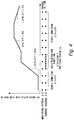
- the control interval ⁇ Tc if the hot water supply-side flow rate Fk is stable, it is preferable to set the control interval ⁇ Tc to be long to a certain extent so as to prevent unnecessary fluctuation in hot water supply temperature. On the other hand, if the hot water supply-side flow rate Fk rapidly fluctuates, it is preferable to set the control interval ⁇ Tc to be short in order to make the heat source-side flow rate Fl promptly follow the rapid fluctuation and thereby reduce or eliminate a difference in hot water supply temperature.
- the control interval ⁇ Tc is variably set according to a degree of stability of the hot water supply-side flow rate Fk.
- ⁇ Fk Fk i ⁇ Fk i ⁇ 1
- the stability degree defined by Expression (2) above has a larger value as the hot water supply-side flow rate more rapidly fluctuates. Therefore, the control section 36 determines that the hot water supply-side flow rate Fk rapidly fluctuates if it is determined that
- the control interval ⁇ Tc the monitoring interval ⁇ Tf (first control interval)
- the control interval ⁇ Tc is set to a control interval ⁇ Tcmin (second control interval), which is shorter than the monitoring interval ⁇ Tf.
- the constant Fa is a threshold value of a stability degree for determining that the hot water supply-side flow rate Fk is stable or rapidly fluctuates, and for the constant Fa, a preset constant is used.
- Such control enables suppression of hunting when the hot water supply-side flow rate is stable and thereby enables prevention of unnecessary fluctuation of hot water supply temperature, and also enables enhancement in control responsiveness when the hot water supply-side flow rate rapidly fluctuates and thus reduction or elimination of a difference in hot water supply temperature.
- a rapid fluctuation period Ta is provided to prevent frequent switching between stable condition and rapid fluctuation condition, and during a fixed period from the transition to the rapid fluctuation condition until an elapse of the rapid fluctuation period Ta, PID control for a rapid fluctuation condition is maintained. Consequently, complicated switching of the control interval ⁇ Tc is prevented, enabling ensuring hot water supply temperature stability.
- gain changing means for changing each gain of PID control to a second gain that is larger than a first gain for a stable condition is activated, enabling further control responsiveness enhancement.
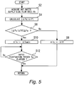
- Fig. 5 is a flowchart of a routine for the control section 36 to set a control interval ⁇ Tc in Embodiment 1 of the present invention.
- the routine illustrated in Fig. 5 is executed for each monitoring interval ⁇ Tf.
- a hot water supply-side flow rate Fk is acquired by the hot water supply flow rate sensor 49 (step S2).
- which is an absolute value of an amount of temporal change in the hot water supply-side flow rate Fk is calculated (step S4).
- is calculated by substituting a hot water supply-side flow rate Fk(i) in the present routine and a hot water supply-side flow rate Fk (i-1) in the last routine into Expression (2) above.
- step S6 whether or not
- ⁇ Fa it is determined that the hot water supply-side flow rate Fk is stable, and the routine proceeds to the next step, and a control interval ⁇ Tc in PID control of a heat source-side flow rate Fl is set to be equal to the monitoring interval ⁇ Tf (step S8).
- step S6 determines whether or not the hot water supply-side flow rate Fk rapidly fluctuates, and the routine proceeds to next step and the control interval ⁇ Tc in the PID control of the heat source-side flow rate Fl is set to a control interval ⁇ Tcmin, which is shorter than the monitoring interval ⁇ Tf (step S10).
- step S12 determines whether or not the rapid fluctuation period Ta has elapsed. As a result, if the rapid fluctuation period Ta has not yet elapsed, the processing in step S12 is repeated until an elapse of the rapid fluctuation period Ta. After the above processing in step S8, or if it is determined in step S12 above that the rapid fluctuation period Ta has elapsed, the present routine ends, and the routine illustrated in Fig. 5 is executed again from the beginning.
- Fig. 6 is a flowchart of a routine for the control section 36 to perform control of a heat source-side flow rate in Embodiment 1 of the present invention.
- the routine illustrated in Fig. 6 is repeated for each control interval ⁇ Tc set in the routine illustrated in Fig. 5 .
- a hot water supply-side flow rate Fk is acquired by the hot water supply flow rate sensor 49 (step S20).
- a heat source-side flow rate Fl is acquired by the hot water supply heat source flow rate sensor 50 (step S22).
- a target flow rate Ftgt for the heat source-side flow rate is set (step S24).
- the target flow rate Ftgt is set to be equal to the hot water supply-side flow rate Fk acquired in step S20 above.
- an input voltage Vp of the hot water supply heat source pump 48 is subjected to PID control using Expression (1) above so as to bring the heat source-side flow rate Fl acquired in step S22 above to the target flow rate Ftgt set in step S24 above (step S26).
- the storage water heater according to the present embodiment enables enhancement in flow rate responsiveness to rapid fluctuation even if there is fluctuation in hot water supply-side flow rate and also enables suppression of unnecessary flow rate fluctuation when the flow rate is stable. Consequently, a tapping temperature can be stabilized, enabling a hot water supply operation without giving a feeling discomfort to a user.
- PID control of the heat source-side flow rate Fl is performed, other feedback control that controls an input voltage Vp of the hot water supply heat source pump 48 so as to bring the heat source-side flow rate Fl to the target flow rate Ftgt may be used.
- control interval ⁇ Tc is maintained at ⁇ Tcmin, such control is not necessarily essential in the present invention.
- PID control of the heat source-side flow rate Fl when the hot water supply-side flow rate Fk rapidly fluctuates, gains are made to be large compared to those when the hot water supply-side flow rate Fk is stable, such control is not necessarily essential in the present invention.
- the intended gains are not limited to all of the proportional gain Kp, the integral gain Ki and the derivative gain Kd, and may be any of these gains.
- a storage water heater according to Embodiment 2 can be provided by making a control section 36 execute the routine illustrated in Fig. 5 and a routine illustrated in Fig. 7 , which will be described later, using the hardware configuration illustrated in Fig. 1 .
- a heat source-side flow rate Fl is detected by the hot water supply heat source flow rate sensor 50 and an input voltage Vp of the hot water supply heat source pump 48 is subjected to feedback control so as to bring the detected heat source-side flow rate Fl to a target flow rate Ftgt.
- a configuration of the hot water supply heat source conduit 46 does not change during a hot water supply operation.
- Fig. 7 is a flowchart of a routine for the control section 36 to perform control of a heat source-side flow rate in Embodiment 2 of the present invention.
- the routine illustrated in Fig. 7 is repeated for each control interval ⁇ Tc set in the routine illustrated in Fig. 5 .
- a hot water supply-side flow rate Fk is acquired by a hot water supply flow rate sensor 49 (step S30).
- a target flow rate Ftgt for the heat source-side flow rate is set (step S32).
- the target flow rate Ftgt is set to be equal to the hot water supply-side flow rate Fk acquired in step S20 above.
- an input voltage Vp for achieving the target flow rate Ftgt set in step S32 above is identified. Then, the input voltage Vp of the hot water supply heat source pump 48 is controlled to be the identified input voltage Vp (step S34).
- the storage water heater according to the present embodiment enables, even when there is fluctuation in a hot water supply-side flow rate, enhancement in flow rate responsiveness in a rapid fluctuation condition and also enables suppression in unnecessary flow rate fluctuation when the flow rate is stable. Consequently, a tapping temperature can be stabilized, enabling a hot water supply operation without giving a feeling of discomfort to a user. Also, the storage water heater according to the present embodiment enables control of a heat source-side flow rate Fl to be a target flow rate Ftgt even with a hardware configuration including no hot water supply heat source flow rate sensor 50.
Landscapes
- Engineering & Computer Science (AREA)
- Physics & Mathematics (AREA)
- Thermal Sciences (AREA)
- Chemical & Material Sciences (AREA)
- Combustion & Propulsion (AREA)
- Mechanical Engineering (AREA)
- General Engineering & Computer Science (AREA)
- Heat-Pump Type And Storage Water Heaters (AREA)
Claims (6)
- Speicher-Wassererwärmer (35), umfassend:einen Warmwasserspeichertank (8), der Warmwasser speichert;Heizmittel (7) zum Erwärmen von im Warmwasserspeichertank (8) gespeichertem Warmwasser;einen Warmwasserversorgungswärmetauscher (52) zum Durchführen von Wärmeaustausch zwischen Warmwasser, das von einem oberen Abschnitt des Warmwasserspeichertanks (8) geliefert wird, und Versorgungswasser;eine Versorgungswasserleitung (9), die das Versorgungswasser über den Warmwasserversorgungswärmetauscher (52) zu einem Warmwasserversorgungsanschluss (51) leitet;eine Warmwasserversorgungs-Wärmequellenleitung (46), die Wasser über den Warmwasserversorgungswärmetauscher (52) von dem oberen Abschnitt des Warmwasserspeichertanks (8) zu einem unteren Abschnitt des Warmwasserspeichertanks (8) führt;eine Warmwasserversorgungs-Wärmequellenpumpe (48), die Wasser in der Warmwasserversorgungs-Wärmequellenleitung (46) zirkuliert; undPumpensteuermittel (36) zum Berechnen einer Fördermenge der Warmwasserversorgungs-Wärmequellenpumpe (48) in einem Warmwasserversorgungsbetrieb, in dem Warmwasser an den Warmwasserversorgungsanschluss (51) geliefert wird, wobei die Fördermenge eine wärmequellenseitige Durchflussmenge, die eine Durchflussmenge von in der Warmwasserversorgungs-Wärmequellenleitung (46) strömenden Warmasser ist, für jedes Steuerintervall auf eine Soll-Durchflussmenge bringt und die Warmwasserversorgungs-Wärmequellenpumpe (48) auf Grundlage des berechneten Durchsatzes steuert,wobei die Pumpensteuereinrichtung (36) ein Steuerintervalländerungsmittel zum Ändern des Steuerintervalls auf Grundlage eines Betrags einer zeitlichen Änderung einer warmwasserversorgungsseitigen Durchflussmenge, die eine Durchflussmenge von in der Versorgungswasserleitung (9) strömendem Versorgungswasser ist, umfasst,dadurch gekennzeichnet, dass, wenn der Umfang der zeitlichen Änderung der warmwasserversorgungseitigen Durchflussmenge einen Schwellenwert überschreitet, das Steuerintervalländerungsmittel das Steuerintervall von einem ersten Steuerintervall in ein zweites Steuerintervall, das kürzer ist als das erste Steuerintervall, ändert.
- Speicher-Wassererwärmer (35) nach Anspruch 1, wobei, wenn das Steuerintervall von dem ersten Steuerintervall in das zweite Steuerintervall geändert wird, das Steuerintervalländerungsmittel das Steuerintervall für einen bestimmten Zeitraum nach der Änderung auf dem zweiten Steuerintervall aufrechthält.
- Speicher-Wassererwärmer (35) nach Anspruch 1 oder 2, ferner umfassend einen Warmwasserversorgungs-Wärmequellen-Durchflusssensor (50), der den wärmequellenseitigen Durchfluss erfasst,
wobei die Pumpensteuereinrichtung (36) ein Regelungsmittel umfasst, um die Fördermenge der Warmwasserversorgungswärmequellenpumpe (48) einer Regelung zu unterziehen, so dass der vom Warmwasserversorgungs-Wärmequellen-Durchflusssensor (50) erfasste wärmequellenseitige Durchfluss die Soll-Durchflussmenge erreicht. - Speicher-Wassererwärmer (35) nach Anspruch 3, wobei die Pumpensteuereinrichtung (36) ein Verstärkungsänderungsmittel beinhaltet, um, wenn der absolute Wert einen Schwellenwert überschreitet, eine Verstärkung der Regelung von einer ersten Verstärkung auf eine zweite Verstärkung, die größer ist als die erste Verstärkung, zu ändern.
- Speicher-Wassererwärmer (35) nach einem der Ansprüche 1 bis 4, umfassend einen Warmwasserversorgungs-Durchflusssensor, der eine warmwasserversorgungsseitige Durchflussmenge erfasst, die eine Durchflussmenge von Warmwasser ist, das in der Versorgungswasserleitung (9) strömt, wobei
die Pumpensteuereinrichtung (36) ein Sollwerteinstellmittel zum Einstellen der Soll-Durchflussmenge auf Grundlage der warmwasserversorgungsseitigen Durchflussmenge umfasst. - Speicher-Wassererwärmer (35) nach einem der Ansprüche 1 bis 5, wobei die Pumpensteuereinrichtung (36) ein Berechnungsmittel zum Berechnen des Betrags der zeitlichen Änderung der warmwasserversorgungsseitigen Durchflussmenge für jedes Überwachungsintervall umfasst.
Applications Claiming Priority (1)
| Application Number | Priority Date | Filing Date | Title |
|---|---|---|---|
| PCT/JP2014/063725 WO2015177929A1 (ja) | 2014-05-23 | 2014-05-23 | 貯湯式給湯機 |
Publications (3)
| Publication Number | Publication Date |
|---|---|
| EP3147583A1 EP3147583A1 (de) | 2017-03-29 |
| EP3147583A4 EP3147583A4 (de) | 2018-03-28 |
| EP3147583B1 true EP3147583B1 (de) | 2019-03-13 |
Family
ID=54553620
Family Applications (1)
| Application Number | Title | Priority Date | Filing Date |
|---|---|---|---|
| EP14892601.7A Active EP3147583B1 (de) | 2014-05-23 | 2014-05-23 | Heisswasserspeicher |
Country Status (3)
| Country | Link |
|---|---|
| EP (1) | EP3147583B1 (de) |
| JP (1) | JP6160772B2 (de) |
| WO (1) | WO2015177929A1 (de) |
Cited By (2)
| Publication number | Priority date | Publication date | Assignee | Title |
|---|---|---|---|---|
| EP4265978A4 (de) * | 2021-01-22 | 2024-01-31 | Mitsubishi Electric Corporation | Heisswasserversorgungsvorrichtung mit warmwasserspeicher |
| EP3816522B1 (de) * | 2019-10-31 | 2024-02-28 | Robert Bosch GmbH | Verfahren zur steuerung einer wärmevorrichtung |
Families Citing this family (4)
| Publication number | Priority date | Publication date | Assignee | Title |
|---|---|---|---|---|
| EP3412985B1 (de) * | 2016-02-02 | 2021-03-24 | Mitsubishi Electric Corporation | Verfahren zur steuerung eines wasserheizsystems und wasserheizsystem |
| MX385677B (es) * | 2016-03-29 | 2025-03-18 | Basf Se | Contenedor de transporte apto para vigilancia remota. |
| EP4202316B1 (de) * | 2019-05-10 | 2024-08-07 | Mitsubishi Electric Corporation | Wärmespeichersystem |
| CN116697795B (zh) * | 2023-06-08 | 2025-11-25 | 中山市思源电器有限公司 | 换热装置及热水器 |
Family Cites Families (7)
| Publication number | Priority date | Publication date | Assignee | Title |
|---|---|---|---|---|
| JP4197089B2 (ja) * | 2000-10-13 | 2008-12-17 | 株式会社デンソー | 給湯器 |
| DE10208772A1 (de) * | 2002-02-28 | 2003-10-02 | Henke Sass Wolf Gmbh | Steuergerät und Verfahren zur Steuerung einer Umwälzpumpe |
| JP4070627B2 (ja) * | 2003-02-12 | 2008-04-02 | 株式会社デンソー | 多機能給湯装置 |
| JP2009103444A (ja) * | 2009-01-13 | 2009-05-14 | Mitsubishi Electric Engineering Co Ltd | 電気湯沸し装置 |
| JP5310432B2 (ja) * | 2009-09-17 | 2013-10-09 | パナソニック株式会社 | ヒートポンプ式温水暖房装置 |
| JP5831383B2 (ja) * | 2012-07-20 | 2015-12-09 | 三菱電機株式会社 | 貯湯式給湯機 |
| JP5835140B2 (ja) * | 2012-07-23 | 2015-12-24 | 三菱電機株式会社 | 貯湯式給湯機 |
-
2014
- 2014-05-23 EP EP14892601.7A patent/EP3147583B1/de active Active
- 2014-05-23 JP JP2016520896A patent/JP6160772B2/ja active Active
- 2014-05-23 WO PCT/JP2014/063725 patent/WO2015177929A1/ja not_active Ceased
Non-Patent Citations (1)
| Title |
|---|
| None * |
Cited By (2)
| Publication number | Priority date | Publication date | Assignee | Title |
|---|---|---|---|---|
| EP3816522B1 (de) * | 2019-10-31 | 2024-02-28 | Robert Bosch GmbH | Verfahren zur steuerung einer wärmevorrichtung |
| EP4265978A4 (de) * | 2021-01-22 | 2024-01-31 | Mitsubishi Electric Corporation | Heisswasserversorgungsvorrichtung mit warmwasserspeicher |
Also Published As
| Publication number | Publication date |
|---|---|
| JP6160772B2 (ja) | 2017-07-12 |
| JPWO2015177929A1 (ja) | 2017-04-20 |
| WO2015177929A1 (ja) | 2015-11-26 |
| EP3147583A1 (de) | 2017-03-29 |
| EP3147583A4 (de) | 2018-03-28 |
Similar Documents
| Publication | Publication Date | Title |
|---|---|---|
| EP3147583B1 (de) | Heisswasserspeicher | |
| EP2407729A1 (de) | Heisswasserversorgungssystem | |
| RU2678888C2 (ru) | Способ регулирования для системы отопления и/или охлаждения с по меньшей мере одним нагрузочным контуром, а также распределительное устройство для системы отопления и/или охлаждения | |
| CN106869249B (zh) | 增压装置 | |
| US9951970B2 (en) | Immediate hot-water supplying system | |
| RU2723274C2 (ru) | Комбинированный теплофикационный и водогрейный котел и способ управления им | |
| EP2957839B1 (de) | Warmwasserversorgungsvorrichtung | |
| JP5101548B2 (ja) | 給湯システム | |
| RU2013100183A (ru) | Система регулирования температуры и способ регулирования температуры в помещении | |
| JP6129033B2 (ja) | 給湯システム | |
| KR20220090706A (ko) | 직수형 정수기 및 그 가열 제어방법 | |
| KR101749125B1 (ko) | 순간 온수 공급시스템 및 그 제어방법 | |
| US11453581B2 (en) | Hot liquid supply apparatus and method for controlling same | |
| US11286147B2 (en) | Hot-liquid supply device and method for controlling same | |
| JP2015113986A (ja) | 給湯装置 | |
| JP7765983B2 (ja) | 給湯システム | |
| JP2016186764A (ja) | 湯水混合装置 | |
| JP4319237B2 (ja) | ヒートポンプ給湯器 | |
| JP2012078041A (ja) | 貯湯式給湯装置 | |
| WO2015182005A1 (ja) | 貯湯式給湯機 | |
| JP6757967B2 (ja) | 給湯システム | |
| JP6240515B2 (ja) | 給湯装置 | |
| JP5928511B2 (ja) | 給湯装置 | |
| KR101621189B1 (ko) | 급탕 시스템 | |
| JP6086820B2 (ja) | 給湯装置 |
Legal Events
| Date | Code | Title | Description |
|---|---|---|---|
| STAA | Information on the status of an ep patent application or granted ep patent |
Free format text: STATUS: THE INTERNATIONAL PUBLICATION HAS BEEN MADE |
|
| PUAI | Public reference made under article 153(3) epc to a published international application that has entered the european phase |
Free format text: ORIGINAL CODE: 0009012 |
|
| STAA | Information on the status of an ep patent application or granted ep patent |
Free format text: STATUS: REQUEST FOR EXAMINATION WAS MADE |
|
| 17P | Request for examination filed |
Effective date: 20161222 |
|
| AK | Designated contracting states |
Kind code of ref document: A1 Designated state(s): AL AT BE BG CH CY CZ DE DK EE ES FI FR GB GR HR HU IE IS IT LI LT LU LV MC MK MT NL NO PL PT RO RS SE SI SK SM TR |
|
| AX | Request for extension of the european patent |
Extension state: BA ME |
|
| DAX | Request for extension of the european patent (deleted) | ||
| A4 | Supplementary search report drawn up and despatched |
Effective date: 20180226 |
|
| RIC1 | Information provided on ipc code assigned before grant |
Ipc: F24D 17/02 20060101ALI20180220BHEP Ipc: F24D 19/10 20060101ALI20180220BHEP Ipc: F24H 1/18 20060101AFI20180220BHEP Ipc: F24D 17/00 20060101ALI20180220BHEP |
|
| GRAP | Despatch of communication of intention to grant a patent |
Free format text: ORIGINAL CODE: EPIDOSNIGR1 |
|
| STAA | Information on the status of an ep patent application or granted ep patent |
Free format text: STATUS: GRANT OF PATENT IS INTENDED |
|
| INTG | Intention to grant announced |
Effective date: 20181002 |
|
| GRAS | Grant fee paid |
Free format text: ORIGINAL CODE: EPIDOSNIGR3 |
|
| GRAA | (expected) grant |
Free format text: ORIGINAL CODE: 0009210 |
|
| STAA | Information on the status of an ep patent application or granted ep patent |
Free format text: STATUS: THE PATENT HAS BEEN GRANTED |
|
| AK | Designated contracting states |
Kind code of ref document: B1 Designated state(s): AL AT BE BG CH CY CZ DE DK EE ES FI FR GB GR HR HU IE IS IT LI LT LU LV MC MK MT NL NO PL PT RO RS SE SI SK SM TR |
|
| REG | Reference to a national code |
Ref country code: GB Ref legal event code: FG4D |
|
| REG | Reference to a national code |
Ref country code: CH Ref legal event code: EP Ref country code: AT Ref legal event code: REF Ref document number: 1108256 Country of ref document: AT Kind code of ref document: T Effective date: 20190315 |
|
| REG | Reference to a national code |
Ref country code: IE Ref legal event code: FG4D |
|
| REG | Reference to a national code |
Ref country code: DE Ref legal event code: R096 Ref document number: 602014043081 Country of ref document: DE |
|
| REG | Reference to a national code |
Ref country code: NL Ref legal event code: MP Effective date: 20190313 |
|
| REG | Reference to a national code |
Ref country code: LT Ref legal event code: MG4D |
|
| PG25 | Lapsed in a contracting state [announced via postgrant information from national office to epo] |
Ref country code: FI Free format text: LAPSE BECAUSE OF FAILURE TO SUBMIT A TRANSLATION OF THE DESCRIPTION OR TO PAY THE FEE WITHIN THE PRESCRIBED TIME-LIMIT Effective date: 20190313 Ref country code: LT Free format text: LAPSE BECAUSE OF FAILURE TO SUBMIT A TRANSLATION OF THE DESCRIPTION OR TO PAY THE FEE WITHIN THE PRESCRIBED TIME-LIMIT Effective date: 20190313 Ref country code: SE Free format text: LAPSE BECAUSE OF FAILURE TO SUBMIT A TRANSLATION OF THE DESCRIPTION OR TO PAY THE FEE WITHIN THE PRESCRIBED TIME-LIMIT Effective date: 20190313 Ref country code: NO Free format text: LAPSE BECAUSE OF FAILURE TO SUBMIT A TRANSLATION OF THE DESCRIPTION OR TO PAY THE FEE WITHIN THE PRESCRIBED TIME-LIMIT Effective date: 20190613 |
|
| PG25 | Lapsed in a contracting state [announced via postgrant information from national office to epo] |
Ref country code: GR Free format text: LAPSE BECAUSE OF FAILURE TO SUBMIT A TRANSLATION OF THE DESCRIPTION OR TO PAY THE FEE WITHIN THE PRESCRIBED TIME-LIMIT Effective date: 20190614 Ref country code: NL Free format text: LAPSE BECAUSE OF FAILURE TO SUBMIT A TRANSLATION OF THE DESCRIPTION OR TO PAY THE FEE WITHIN THE PRESCRIBED TIME-LIMIT Effective date: 20190313 Ref country code: HR Free format text: LAPSE BECAUSE OF FAILURE TO SUBMIT A TRANSLATION OF THE DESCRIPTION OR TO PAY THE FEE WITHIN THE PRESCRIBED TIME-LIMIT Effective date: 20190313 Ref country code: LV Free format text: LAPSE BECAUSE OF FAILURE TO SUBMIT A TRANSLATION OF THE DESCRIPTION OR TO PAY THE FEE WITHIN THE PRESCRIBED TIME-LIMIT Effective date: 20190313 Ref country code: BG Free format text: LAPSE BECAUSE OF FAILURE TO SUBMIT A TRANSLATION OF THE DESCRIPTION OR TO PAY THE FEE WITHIN THE PRESCRIBED TIME-LIMIT Effective date: 20190613 Ref country code: RS Free format text: LAPSE BECAUSE OF FAILURE TO SUBMIT A TRANSLATION OF THE DESCRIPTION OR TO PAY THE FEE WITHIN THE PRESCRIBED TIME-LIMIT Effective date: 20190313 |
|
| REG | Reference to a national code |
Ref country code: AT Ref legal event code: MK05 Ref document number: 1108256 Country of ref document: AT Kind code of ref document: T Effective date: 20190313 |
|
| PG25 | Lapsed in a contracting state [announced via postgrant information from national office to epo] |
Ref country code: IT Free format text: LAPSE BECAUSE OF FAILURE TO SUBMIT A TRANSLATION OF THE DESCRIPTION OR TO PAY THE FEE WITHIN THE PRESCRIBED TIME-LIMIT Effective date: 20190313 Ref country code: EE Free format text: LAPSE BECAUSE OF FAILURE TO SUBMIT A TRANSLATION OF THE DESCRIPTION OR TO PAY THE FEE WITHIN THE PRESCRIBED TIME-LIMIT Effective date: 20190313 Ref country code: CZ Free format text: LAPSE BECAUSE OF FAILURE TO SUBMIT A TRANSLATION OF THE DESCRIPTION OR TO PAY THE FEE WITHIN THE PRESCRIBED TIME-LIMIT Effective date: 20190313 Ref country code: RO Free format text: LAPSE BECAUSE OF FAILURE TO SUBMIT A TRANSLATION OF THE DESCRIPTION OR TO PAY THE FEE WITHIN THE PRESCRIBED TIME-LIMIT Effective date: 20190313 Ref country code: ES Free format text: LAPSE BECAUSE OF FAILURE TO SUBMIT A TRANSLATION OF THE DESCRIPTION OR TO PAY THE FEE WITHIN THE PRESCRIBED TIME-LIMIT Effective date: 20190313 Ref country code: AL Free format text: LAPSE BECAUSE OF FAILURE TO SUBMIT A TRANSLATION OF THE DESCRIPTION OR TO PAY THE FEE WITHIN THE PRESCRIBED TIME-LIMIT Effective date: 20190313 Ref country code: PT Free format text: LAPSE BECAUSE OF FAILURE TO SUBMIT A TRANSLATION OF THE DESCRIPTION OR TO PAY THE FEE WITHIN THE PRESCRIBED TIME-LIMIT Effective date: 20190713 Ref country code: SK Free format text: LAPSE BECAUSE OF FAILURE TO SUBMIT A TRANSLATION OF THE DESCRIPTION OR TO PAY THE FEE WITHIN THE PRESCRIBED TIME-LIMIT Effective date: 20190313 |
|
| PG25 | Lapsed in a contracting state [announced via postgrant information from national office to epo] |
Ref country code: PL Free format text: LAPSE BECAUSE OF FAILURE TO SUBMIT A TRANSLATION OF THE DESCRIPTION OR TO PAY THE FEE WITHIN THE PRESCRIBED TIME-LIMIT Effective date: 20190313 Ref country code: SM Free format text: LAPSE BECAUSE OF FAILURE TO SUBMIT A TRANSLATION OF THE DESCRIPTION OR TO PAY THE FEE WITHIN THE PRESCRIBED TIME-LIMIT Effective date: 20190313 |
|
| REG | Reference to a national code |
Ref country code: DE Ref legal event code: R119 Ref document number: 602014043081 Country of ref document: DE |
|
| REG | Reference to a national code |
Ref country code: CH Ref legal event code: PL |
|
| PG25 | Lapsed in a contracting state [announced via postgrant information from national office to epo] |
Ref country code: AT Free format text: LAPSE BECAUSE OF FAILURE TO SUBMIT A TRANSLATION OF THE DESCRIPTION OR TO PAY THE FEE WITHIN THE PRESCRIBED TIME-LIMIT Effective date: 20190313 Ref country code: IS Free format text: LAPSE BECAUSE OF FAILURE TO SUBMIT A TRANSLATION OF THE DESCRIPTION OR TO PAY THE FEE WITHIN THE PRESCRIBED TIME-LIMIT Effective date: 20190713 |
|
| PLBE | No opposition filed within time limit |
Free format text: ORIGINAL CODE: 0009261 |
|
| STAA | Information on the status of an ep patent application or granted ep patent |
Free format text: STATUS: NO OPPOSITION FILED WITHIN TIME LIMIT |
|
| PG25 | Lapsed in a contracting state [announced via postgrant information from national office to epo] |
Ref country code: MC Free format text: LAPSE BECAUSE OF FAILURE TO SUBMIT A TRANSLATION OF THE DESCRIPTION OR TO PAY THE FEE WITHIN THE PRESCRIBED TIME-LIMIT Effective date: 20190313 Ref country code: LI Free format text: LAPSE BECAUSE OF NON-PAYMENT OF DUE FEES Effective date: 20190531 Ref country code: CH Free format text: LAPSE BECAUSE OF NON-PAYMENT OF DUE FEES Effective date: 20190531 Ref country code: DK Free format text: LAPSE BECAUSE OF FAILURE TO SUBMIT A TRANSLATION OF THE DESCRIPTION OR TO PAY THE FEE WITHIN THE PRESCRIBED TIME-LIMIT Effective date: 20190313 |
|
| REG | Reference to a national code |
Ref country code: BE Ref legal event code: MM Effective date: 20190531 |
|
| 26N | No opposition filed |
Effective date: 20191216 |
|
| PG25 | Lapsed in a contracting state [announced via postgrant information from national office to epo] |
Ref country code: LU Free format text: LAPSE BECAUSE OF NON-PAYMENT OF DUE FEES Effective date: 20190523 Ref country code: SI Free format text: LAPSE BECAUSE OF FAILURE TO SUBMIT A TRANSLATION OF THE DESCRIPTION OR TO PAY THE FEE WITHIN THE PRESCRIBED TIME-LIMIT Effective date: 20190313 |
|
| PG25 | Lapsed in a contracting state [announced via postgrant information from national office to epo] |
Ref country code: TR Free format text: LAPSE BECAUSE OF FAILURE TO SUBMIT A TRANSLATION OF THE DESCRIPTION OR TO PAY THE FEE WITHIN THE PRESCRIBED TIME-LIMIT Effective date: 20190313 |
|
| PG25 | Lapsed in a contracting state [announced via postgrant information from national office to epo] |
Ref country code: IE Free format text: LAPSE BECAUSE OF NON-PAYMENT OF DUE FEES Effective date: 20190523 Ref country code: DE Free format text: LAPSE BECAUSE OF NON-PAYMENT OF DUE FEES Effective date: 20191203 |
|
| PG25 | Lapsed in a contracting state [announced via postgrant information from national office to epo] |
Ref country code: BE Free format text: LAPSE BECAUSE OF NON-PAYMENT OF DUE FEES Effective date: 20190531 |
|
| PG25 | Lapsed in a contracting state [announced via postgrant information from national office to epo] |
Ref country code: FR Free format text: LAPSE BECAUSE OF NON-PAYMENT OF DUE FEES Effective date: 20190531 |
|
| PG25 | Lapsed in a contracting state [announced via postgrant information from national office to epo] |
Ref country code: CY Free format text: LAPSE BECAUSE OF FAILURE TO SUBMIT A TRANSLATION OF THE DESCRIPTION OR TO PAY THE FEE WITHIN THE PRESCRIBED TIME-LIMIT Effective date: 20190313 |
|
| PG25 | Lapsed in a contracting state [announced via postgrant information from national office to epo] |
Ref country code: MT Free format text: LAPSE BECAUSE OF FAILURE TO SUBMIT A TRANSLATION OF THE DESCRIPTION OR TO PAY THE FEE WITHIN THE PRESCRIBED TIME-LIMIT Effective date: 20190313 Ref country code: HU Free format text: LAPSE BECAUSE OF FAILURE TO SUBMIT A TRANSLATION OF THE DESCRIPTION OR TO PAY THE FEE WITHIN THE PRESCRIBED TIME-LIMIT; INVALID AB INITIO Effective date: 20140523 |
|
| REG | Reference to a national code |
Ref country code: GB Ref legal event code: 746 Effective date: 20220509 |
|
| PG25 | Lapsed in a contracting state [announced via postgrant information from national office to epo] |
Ref country code: MK Free format text: LAPSE BECAUSE OF FAILURE TO SUBMIT A TRANSLATION OF THE DESCRIPTION OR TO PAY THE FEE WITHIN THE PRESCRIBED TIME-LIMIT Effective date: 20190313 |
|
| PGFP | Annual fee paid to national office [announced via postgrant information from national office to epo] |
Ref country code: GB Payment date: 20250401 Year of fee payment: 12 |