EP3147617B1 - Wärmetauscher - Google Patents
Wärmetauscher Download PDFInfo
- Publication number
- EP3147617B1 EP3147617B1 EP15796142.6A EP15796142A EP3147617B1 EP 3147617 B1 EP3147617 B1 EP 3147617B1 EP 15796142 A EP15796142 A EP 15796142A EP 3147617 B1 EP3147617 B1 EP 3147617B1
- Authority
- EP
- European Patent Office
- Prior art keywords
- storage body
- heat storage
- heat
- passage
- phase
- Prior art date
- Legal status (The legal status is an assumption and is not a legal conclusion. Google has not performed a legal analysis and makes no representation as to the accuracy of the status listed.)
- Not-in-force
Links
Images

Classifications
-
- B—PERFORMING OPERATIONS; TRANSPORTING
- B60—VEHICLES IN GENERAL
- B60H—ARRANGEMENTS OF HEATING, COOLING, VENTILATING OR OTHER AIR-TREATING DEVICES SPECIALLY ADAPTED FOR PASSENGER OR GOODS SPACES OF VEHICLES
- B60H1/00—Heating, cooling or ventilating devices
- B60H1/00492—Heating, cooling or ventilating devices comprising regenerative heating or cooling means, e.g. heat accumulators
- B60H1/005—Regenerative cooling means, e.g. cold accumulators
-
- B—PERFORMING OPERATIONS; TRANSPORTING
- B60—VEHICLES IN GENERAL
- B60H—ARRANGEMENTS OF HEATING, COOLING, VENTILATING OR OTHER AIR-TREATING DEVICES SPECIALLY ADAPTED FOR PASSENGER OR GOODS SPACES OF VEHICLES
- B60H1/00—Heating, cooling or ventilating devices
- B60H1/00321—Heat exchangers for air-conditioning devices
- B60H1/00335—Heat exchangers for air-conditioning devices of the gas-air type
-
- C—CHEMISTRY; METALLURGY
- C09—DYES; PAINTS; POLISHES; NATURAL RESINS; ADHESIVES; COMPOSITIONS NOT OTHERWISE PROVIDED FOR; APPLICATIONS OF MATERIALS NOT OTHERWISE PROVIDED FOR
- C09K—MATERIALS FOR MISCELLANEOUS APPLICATIONS, NOT PROVIDED FOR ELSEWHERE
- C09K5/00—Heat-transfer, heat-exchange or heat-storage materials, e.g. refrigerants; Materials for the production of heat or cold by chemical reactions other than by combustion
- C09K5/02—Materials undergoing a change of physical state when used
- C09K5/06—Materials undergoing a change of physical state when used the change of state being from liquid to solid or vice versa
- C09K5/066—Cooling mixtures; De-icing compositions
-
- F—MECHANICAL ENGINEERING; LIGHTING; HEATING; WEAPONS; BLASTING
- F28—HEAT EXCHANGE IN GENERAL
- F28D—HEAT-EXCHANGE APPARATUS, NOT PROVIDED FOR IN ANOTHER SUBCLASS, IN WHICH THE HEAT-EXCHANGE MEDIA DO NOT COME INTO DIRECT CONTACT
- F28D1/00—Heat-exchange apparatus having stationary conduit assemblies for one heat-exchange medium only, the media being in contact with different sides of the conduit wall, in which the other heat-exchange medium is a large body of fluid, e.g. domestic or motor car radiators
- F28D1/02—Heat-exchange apparatus having stationary conduit assemblies for one heat-exchange medium only, the media being in contact with different sides of the conduit wall, in which the other heat-exchange medium is a large body of fluid, e.g. domestic or motor car radiators with heat-exchange conduits immersed in the body of fluid
- F28D1/04—Heat-exchange apparatus having stationary conduit assemblies for one heat-exchange medium only, the media being in contact with different sides of the conduit wall, in which the other heat-exchange medium is a large body of fluid, e.g. domestic or motor car radiators with heat-exchange conduits immersed in the body of fluid with tubular conduits
- F28D1/053—Heat-exchange apparatus having stationary conduit assemblies for one heat-exchange medium only, the media being in contact with different sides of the conduit wall, in which the other heat-exchange medium is a large body of fluid, e.g. domestic or motor car radiators with heat-exchange conduits immersed in the body of fluid with tubular conduits the conduits being straight
- F28D1/0535—Heat-exchange apparatus having stationary conduit assemblies for one heat-exchange medium only, the media being in contact with different sides of the conduit wall, in which the other heat-exchange medium is a large body of fluid, e.g. domestic or motor car radiators with heat-exchange conduits immersed in the body of fluid with tubular conduits the conduits being straight the conduits having a non-circular cross-section
- F28D1/05366—Assemblies of conduits connected to common headers, e.g. core type radiators
- F28D1/05383—Assemblies of conduits connected to common headers, e.g. core type radiators with multiple rows of conduits or with multi-channel conduits
-
- F—MECHANICAL ENGINEERING; LIGHTING; HEATING; WEAPONS; BLASTING
- F28—HEAT EXCHANGE IN GENERAL
- F28D—HEAT-EXCHANGE APPARATUS, NOT PROVIDED FOR IN ANOTHER SUBCLASS, IN WHICH THE HEAT-EXCHANGE MEDIA DO NOT COME INTO DIRECT CONTACT
- F28D20/00—Heat storage plants or apparatus in general; Regenerative heat-exchange apparatus not covered by groups F28D17/00 or F28D19/00
- F28D20/0056—Heat storage plants or apparatus in general; Regenerative heat-exchange apparatus not covered by groups F28D17/00 or F28D19/00 using solid heat storage material
-
- F—MECHANICAL ENGINEERING; LIGHTING; HEATING; WEAPONS; BLASTING
- F28—HEAT EXCHANGE IN GENERAL
- F28D—HEAT-EXCHANGE APPARATUS, NOT PROVIDED FOR IN ANOTHER SUBCLASS, IN WHICH THE HEAT-EXCHANGE MEDIA DO NOT COME INTO DIRECT CONTACT
- F28D20/00—Heat storage plants or apparatus in general; Regenerative heat-exchange apparatus not covered by groups F28D17/00 or F28D19/00
- F28D20/02—Heat storage plants or apparatus in general; Regenerative heat-exchange apparatus not covered by groups F28D17/00 or F28D19/00 using latent heat
- F28D20/025—Heat storage plants or apparatus in general; Regenerative heat-exchange apparatus not covered by groups F28D17/00 or F28D19/00 using latent heat the latent heat storage material being in direct contact with a heat-exchange medium or with another heat storage material
-
- F—MECHANICAL ENGINEERING; LIGHTING; HEATING; WEAPONS; BLASTING
- F28—HEAT EXCHANGE IN GENERAL
- F28D—HEAT-EXCHANGE APPARATUS, NOT PROVIDED FOR IN ANOTHER SUBCLASS, IN WHICH THE HEAT-EXCHANGE MEDIA DO NOT COME INTO DIRECT CONTACT
- F28D20/00—Heat storage plants or apparatus in general; Regenerative heat-exchange apparatus not covered by groups F28D17/00 or F28D19/00
- F28D2020/0004—Particular heat storage apparatus
- F28D2020/0013—Particular heat storage apparatus the heat storage material being enclosed in elements attached to or integral with heat exchange conduits
-
- F—MECHANICAL ENGINEERING; LIGHTING; HEATING; WEAPONS; BLASTING
- F28—HEAT EXCHANGE IN GENERAL
- F28D—HEAT-EXCHANGE APPARATUS, NOT PROVIDED FOR IN ANOTHER SUBCLASS, IN WHICH THE HEAT-EXCHANGE MEDIA DO NOT COME INTO DIRECT CONTACT
- F28D21/00—Heat-exchange apparatus not covered by any of the groups F28D1/00 - F28D20/00
- F28D2021/0019—Other heat exchangers for particular applications; Heat exchange systems not otherwise provided for
- F28D2021/0068—Other heat exchangers for particular applications; Heat exchange systems not otherwise provided for for refrigerant cycles
-
- F—MECHANICAL ENGINEERING; LIGHTING; HEATING; WEAPONS; BLASTING
- F28—HEAT EXCHANGE IN GENERAL
- F28D—HEAT-EXCHANGE APPARATUS, NOT PROVIDED FOR IN ANOTHER SUBCLASS, IN WHICH THE HEAT-EXCHANGE MEDIA DO NOT COME INTO DIRECT CONTACT
- F28D21/00—Heat-exchange apparatus not covered by any of the groups F28D1/00 - F28D20/00
- F28D2021/0019—Other heat exchangers for particular applications; Heat exchange systems not otherwise provided for
- F28D2021/008—Other heat exchangers for particular applications; Heat exchange systems not otherwise provided for for vehicles
- F28D2021/0085—Evaporators
-
- Y—GENERAL TAGGING OF NEW TECHNOLOGICAL DEVELOPMENTS; GENERAL TAGGING OF CROSS-SECTIONAL TECHNOLOGIES SPANNING OVER SEVERAL SECTIONS OF THE IPC; TECHNICAL SUBJECTS COVERED BY FORMER USPC CROSS-REFERENCE ART COLLECTIONS [XRACs] AND DIGESTS
- Y02—TECHNOLOGIES OR APPLICATIONS FOR MITIGATION OR ADAPTATION AGAINST CLIMATE CHANGE
- Y02E—REDUCTION OF GREENHOUSE GAS [GHG] EMISSIONS, RELATED TO ENERGY GENERATION, TRANSMISSION OR DISTRIBUTION
- Y02E60/00—Enabling technologies; Technologies with a potential or indirect contribution to GHG emissions mitigation
- Y02E60/14—Thermal energy storage
Definitions
- the present disclosure relates to a heat exchanger applied to a cold heat exchanger for a refrigeration cycle.
- US 2010/0252248 discloses a heat exchanger having the features in the preamble of claim 1.
- a refrigeration cycle is used in an air conditioner. It is considered to perform a specific cooling operation on a condition that the refrigeration cycle is stopped.
- a compressor in the refrigeration cycle is driven by an engine for moving a vehicle in a vehicle air conditioner. The refrigeration cycle is thereby stopped when the engine is stopped while the vehicle is stopping moving temporarily.
- a heat exchanger has a cold heat storage body storing a cold heat in an evaporator disposed in the refrigeration cycle (refer to e.g., Patent Literature 1).
- the heat exchanger disclosed in Patent Literature 1 has, as a cold heat storage body, a solid-liquid phase transitional latent heat storage body.
- Patent Literature 1 JP 2014-20758 A
- a case housing a heat storage body other than components e.g., a tube, a fin, a tank etc.
- components e.g., a tube, a fin, a tank etc.
- a size variation range of the heat storage body in the case becomes greater since a density variation range of the heat storage body is large during a phase transition between a solid phase and a liquid phase.
- the case thereby should have a space for the size variation of the heat storage body caused in conjunction with the phase transition such that the case is fully filled with the heat storage body.
- heat is transferred in an order of the heat storage body, the case, a refrigerant passage, and an air passage when a cold heat is dissipated from the heat storage body to the air passage that is a heat transfer target.
- a great thermal resistance is thereby caused between the heat storage body and the case and between the case and the tube (i.e., the refrigerant passage).
- the thermal resistance in the heat dissipation may become large in an entirety of the heat exchanger.
- a supercooling may be caused due to the phase transition while the heat storage body is storing cold heat in a case that the solid-liquid phase transitional latent heat storage body is used as the heat storage body.
- the heat storage body therefore tends not to be solidified due to the supercooling even in a case that the heat storage body stores cold heat at an assumed phase transitional temperature (i.e., an equilibrium melting point). As a result, the heat storage body may not be able to store cold heat sufficiently.
- the present disclosure addresses the above issues, and thus it is an objective of the present disclosure to provide a heat exchanger having a heat storage body, which can reduce a thermal resistance from a heat storage body to a heat transfer target in a heat dissipation and can suppress a supercooling in a heat storage.
- a heat exchanger of the present disclosure has a first passage, a heat storage body, and a second passage, and performs a heat exchange between a first fluid and a second fluid.
- the first fluid flows in the first passage.
- the heat storage body is thermally connected to the first passage and stores a warm heat or a cold heat.
- the second passage is thermally connected to both of the first passage and the heat storage body, and the second fluid flows in the second passage.
- the heat storage body changes to a first phase in a solid state when a temperature of the heat storage body is lower than or equal to a phase transition temperature, and changes to a second phase in a solid state when the temperature of the heat storage body exceeds the phase transition temperature.
- the heat storage body stores or dissipates heat depending on a phase transition between the first phase and the second phase.
- the second passage is formed in the heat storage body integrally with the heat storage body.
- the heat storage body does not change from the liquid state to the solid state in a heat storage since the heat storage body stores or dissipates heat depending on the phase transition between the first phase and the second phase.
- the supercooling thus can be suppressed in the heat storage.
- the heat storage body is kept in a solid state both in the first phase and the second phase since the heat storage body stores or dissipates heat depending on the phase transition between the first phase and the second phase.
- the second passage thus can be formed in the heat storage body integrally with the heat storage body.
- a heat can be transferred from the heat storage body directly to the first passage, i.e., the heat transfer target, in the heat dissipation since a case to house the heat storage body is not necessary.
- the heat resistance thereby can be reduced when the heat storage body dissipates heat to the heat transfer target.
- the heat storage mentioned in the present disclosure includes a meaning of storing a cold heat not only storing a heat having a high temperature.
- the heat dissipation mentioned in the present disclosure includes a meaning of dissipating a cold heat not only dissipating a heat having a high temperature.
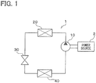
- FIG. 1 shows a configuration of a refrigeration cycle device configuring a vehicle air conditioner.
- the refrigeration cycle device 1 configuring the vehicle air conditioner has a compressor 1, a radiator 20, a pressure reducer 30, and an evaporation device (i.e., an evaporator) 40.
- the components are connected to each other in a circle by a pipe and configure a refrigerant circulation passage.
- the compressor 10 is driven by an internal combustion engine (or a device such as an electric motor) that is a power source 2 for moving a vehicle.
- the compressor 10 is stopped when the power source 2 is stopped.
- the compressor 10 draws refrigerant from the evaporator 40 and discharges the refrigerant to the radiator 20 after compressing the refrigerant.
- the radiator 20 cools a high-temperature refrigerant.
- the radiator 20 is also referred to as a condenser.
- the pressure reducer 30 reduces a pressure of the refrigerant after being cooled in the radiator 20.
- the evaporator 40 evaporates the refrigerant of which pressure is reduced in the pressure reducer 30, and cools air (referred to as an inside air hereinafter) inside a vehicle compartment. That is, the evaporator 40 is a heat exchanger that cools the inside air by performing a heat exchange between the inside air (i.e., a first fluid) and the refrigerant (i.e., a second fluid).
- the inside air thus corresponds to the first fluid of the present disclosure
- the refrigerant thus corresponds to the second fluid of the present disclosure.
- the evaporator 40 is a cold heat storage heat exchanger that stores a cold heat in a heat storage body 41 (refer to FIG. 2 ) when exerting a heat absorption effect by evaporating the refrigerant in the evaporator 20, and that dissipates the cold heat stored while the compressor 10 is being stopped, i.e., while the power source is being stopped.
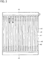
- the evaporator 40 has a core part 43 and a pair of header tanks 44.
- the core part 43 is configured by more than one of the heat storage body 41 and fins 42 that are stacked alternately such that one fin 42 is disposed between adjacent two of the heat storage portions 41.
- An air passage 45 as the first passage in which the inside air flows, is formed between the adjacent two of the heat storage portions 41, i.e., in a portion in which the fin 42 is disposed.
- the heat storage body 41 and the air passage 45 are thermally connected to each other.
- the heat storage body 41 is formed to have a flat shape such that a flow direction or the inside air (referred to as an airflow direction hereinafter) coincides with a major axis direction of the heat storage body 41. More than one of the heat storage body 41 are arranged side by side in the vertical direction to be parallel to each other, and a longitudinal direction of the heat storage body 41 coincides with the horizontal direction.
- the heat storage portion 41 changes to a first phase in a solid state when a temperature of the heat storage portion 41 is lower than or equal to a phase transitional temperature, and changes to a second phase in a solid state when the temperature of the heat storage portion 41 exceeds the phase transitional temperature. That is, the heat storage body 41 is made of a material that is kept in a solid state both in the first phase and the second phase.
- the heat storage body 41 of the present embodiment stores or dissipates heat depending on a phase transition between the first phase and the second phase. The material making the heat storage body 41 will be described in detail later.
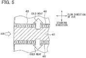
- More than one of a refrigerant passage 46 as a second passage in which the refrigerant flows, are provided inside the heat storage body 41.
- the more than one of the refrigerant passage 46 is formed in the heat storage body 41 integrally with the heat storage body 41.
- the refrigerant evaporates in the refrigerant passage 46 when a heat exchange is performed between the refrigerant and the inside air.
- the refrigerant passage 46 is formed by a through-hole provided in the heat storage body 41 according to the present embodiment.
- the more than one of the refrigerant passage 46 are arranged in the airflow direction in an area of the heat storage body 41 adjacent to the air passage 45. That is, the more than one of the refrigerant passage 46 are arrange in the airflow direction in the heat storage body 41 on both sides in a stacking direction of the heat storage body 41 (referred to as the stacking direction hereinafter).
- Each of the more than one of the refrigerant passage 46 has a rectangular shape in cross section.
- the air passage 45 is arranged between adjacent two of the heat storage bodies 41 as described above. That is, more than one of the air passage 45 are arranged to be distanced from each other.
- the refrigerant passage 46 is arranged between adjacent two of the air passages 45 since the refrigerant passage 46 is formed in the heat storage body 41 integrally with the heat storage body 41.
- the refrigerant passage 46 is thermally connected to both of the air passage 45 and the heat storage body 41.
- the fin 42 is formed to have a corrugate shape and coupled with a flat surface of the heat storage body 41 on both sides of the heat storage body 41.
- the fin 42 increases a heat transfer area that is in contact with the inside air, and promotes a heat exchange between the inside air and the refrigerant flowing in the refrigerant passage 46 provided in the heat storage body 41.
- the pair of header tanks 44 are located on both end of the heat storage body 41 in the longitudinal direction and extend in a direction perpendicular to the longitudinal direction.
- the pair of header tanks 44 communicate with the refrigerant passage 46 provided in the heat storage body 41.
- the header tanks 44 of the present embodiment are arranged on an upper end and a lower end of the heat storage body 41, and extend in the horizontal direction.
- the header tanks 44 communicate with the refrigerant passages 46 of each of the heat storage bodies 41.
- a side plate 47 is provided in each end of the core part 43 in the stacking direction to reinforce the core part 43.
- the side plate 47 extends parallel to the longitudinal direction, and both end of the side plate are connected to the pair of the header tank 44 respectively.
- the evaporator 40 of the present embodiment has the heat storage body 41 that store cold heat as described above.
- the vehicle air conditioner of the present embodiment thus can be switched between a cold heat dissipation mode in which cold heat stored in the heat storage body 41 is transferred to the inside air that is a cooling target fluid and a cold heat storage mode in which cold heat in the refrigerant that is a cold heat source is stored in the heat storage body 41.
- the compressor 10 in the refrigeration cycle device is driven by the power source 2 for moving the vehicle when the vehicle is moving.
- the inside air is cooled by a heat exchange between the inside air and the refrigerant performed in the evaporator 40, and thereby the vehicle compartment is cooled.
- the cold heat storage mode is performed on this occasion, and therefore the cold heat in the refrigerant is stored in the heat storage body 41.
- the refrigeration cycle device is stopped when the power source 2 for moving the vehicle is stopped while the vehicle is being stopped temporarily.
- the cold heat dissipation mode is performed on this occasion, and a specific cooling operation is performed by supplying the cold heat stored to the heat storage body 41 to the inside air.
- the material making the heat storage body 41 of the present embodiment will be described in detail hereafter.
- the heat storage body 41 is configured by a strongly correlated electron chemical compound that has strong coulomb interaction acting between electrons configuring the material.
- the strongly correlated electron chemical compound configuring the heat storage body 41 is a compound, e.g., vanadium dioxide, including at least a transition metal and oxygen according to the present embodiment.
- the strongly correlated electron chemical compound configuring the heat storage body 41 may be a chemical compound expressed by the following chemical formula (1).
- M and N in the chemical formula (1) are transition metals different from each other, and x and y satisfy relations of 0 ⁇ x ⁇ 0.5 and 1.9 ⁇ y ⁇ 2.1.
- the M in the chemical formula (1) may be vanadium.
- the N in the chemical formula (1) may be one of tungsten, rhenium, molybdenum, ruthenium, niobium, and tantalum.
- the phase transitional temperature of the heat storage body 41 can be set at a required temperature by adding a specified amount of a metal element such as tungsten to vanadium dioxide.
- the heat exchange is performed between the inside air and the refrigerant, and the refrigerant evaporates in the refrigerant passage 46.
- the heat storage body 41 of the present embodiment is preferably a strongly correlated electron chemical compound in which the N in the chemical formula (1) is tungsten, and in which the x and the y in the chemical formula (1) satisfy relations of 0.02 ⁇ x ⁇ 0.03 and 1.9 ⁇ y ⁇ 2.1.
- the heat storage body 41 of the present embodiment stores or dissipates heat depending on the phase change between the first phase and the second phase.
- the supercooling during a cold heat storage thereby can be suppressed since a phase of the heat storage body does not change from a liquid phase to a solid phase during the cold heat storage.
- the heat storage body 41 is kept in a solid state both in the first phase and the second phase since the heat storage body stores or dissipates cold heat depending on the phase transition between the first phase and the second phase.
- the refrigerant passage 46 therefore can be formed in the heat storage body 41 integrally with the heat storage body 41.
- a heat can be transferred from the heat storage body 41 directly to the air passage 45, i.e., the heat transfer target, in cold heat dissipation since a case to house the heat storage body 41 is not necessary.
- the heat resistance thereby can be reduced when the heat storage body 41 dissipates cold heat to the heat transfer target.
- a cold heat output from the heat storage body 41 can be improved, and a blowing temperature of the evaporator 40 can be decreased.
- FIG. 4 shows a relation between an idle stop duration of the vehicle and a blowing temperature of air blowing from the evaporator 40.
- the evaporator 40 of the present embodiment configuring the heat storage body 41 by vanadium dioxide can decrease the blowing temperature in the idle stop duration as compared to both a conventional evaporator having no cold heat storage body and a conventional evaporator using paraffin as a cold heat storage body.
- a rise of the blowing temperature can be restricted over a long time, and the idle stop duration can be extended.
- the air passage 45 of the present embodiment is formed integrally with the heat storage body 41. That is, both the refrigeration passage 46 and the air passage 45 are formed in the heat storage body 41 integrally with the heat storage body 41. Specifically, both the refrigeration passage 46 and the air passage 45 are formed in the heat storage body 41 integrally with the heat storage body 41 by providing a through-hole for the refrigeration passage 46 and a through-hole for the air passage 45 in the heat storage body 41.
Landscapes
- Engineering & Computer Science (AREA)
- Physics & Mathematics (AREA)
- Thermal Sciences (AREA)
- Mechanical Engineering (AREA)
- Chemical & Material Sciences (AREA)
- General Engineering & Computer Science (AREA)
- Organic Chemistry (AREA)
- Chemical Kinetics & Catalysis (AREA)
- Combustion & Propulsion (AREA)
- Materials Engineering (AREA)
- Air-Conditioning For Vehicles (AREA)
- Inorganic Chemistry (AREA)
Claims (7)
- Wärmetauscher, umfassend:einen ersten Durchtritt (45), in dem ein erstes Fluid strömt;einen Wärmespeicherkörper (41), der thermisch mit dem ersten Durchtritt (45) verbunden ist und eine warme Wärme oder eine kalte Wärme speichert; und einen zweiten Durchtritt (46), der thermisch sowohl mit dem ersten Durchtritt (45) wie auch mit dem Wärmespeicherkörper (41) verbunden ist, wobei in dem zweiten Durchtritt ein zweites Fluid strömt, wobeider Wärmetauscher einen Wärmetausch zwischen dem ersten Fluid und dem zweiten Fluid durchführt, wobeider Wärmetauscher dadurch gekennzeichnet ist, dassder Wärmespeicherkörper (41) sich in eine erste Phase ändert, die sich in einem festen Zustand befindet, wenn eine Temperatur des Wärmespeicherkörpers (41) niedriger als oder gleich einer Phasenübergangstemperatur ist, und sich in eine zweite Phase in einem festen Zustand ändert, wenn die Temperatur des Wärmespeicherkörpers (41) die Phasenübergangstemperatur überschreitet,der Wärmespeicherkörper (41) Wärme in Abhängigkeit von einem Phasenübergang zwischen der ersten Phase und der zweiten Phase speichert oder abgibt, undder zweite Durchgang (46) in dem Wärmespeicherkörper (41) integral mit dem Wärmespeicherkörper ausgebildet ist.
- Wärmetauscher nach Anspruch 1, wobei
der erste Durchgang (45) einstückig mit dem Wärmespeicherkörper (41) ausgebildet ist. - Wärmetauscher nach Anspruch 1 oder 2, wobei
der Wärmespeicherkörper durch eine stark korrelierte elektronenchemische Verbindung gebildet ist. - Wärmetauscher nach Anspruch 3, wobei
die stark korrelierte elektronenchemische Verbindung mindestens ein Übergangsmetall und Sauerstoff enthält. - Wärmetauscher nach Anspruch 4, wobei
die stark korrelierte elektronenchemische Verbindung eine chemische Verbindung ist, ausgedrückt durch die folgende chemische Formel (1), und wobei
M und N in der chemischen Formel (1) Übergangsmetalle sind, die voneinander verschieden sind, und x und y die Beziehungen von 0 < x ≤ 0,5 und 1,9 < y < 2,1 erfüllen.
M1-x Nx Oy ... (1)
- Wärmetauscher nach Anspruch 5, wobei
das M in der chemischen Formel (1) Vanadium ist, und
das N in der chemischen Formel (1) eines von Wolfram, Rhenium, Molybdän, Ruthenium, Niob und Tantal ist. - Wärmetauscher nach Anspruch 6, wobei
die erste Flüssigkeit Luft ist,
das zweite Fluid ein Kältemittel für einen Kältekreislauf ist,
das zweite Fluid im zweiten Durchtritt (46) verdampft,
das N in der chemischen Formel (1) Wolfram ist und
das x und das y in der chemischen Formel (1) die Beziehungen von 0,02 < x < 0,03 und 1,9 < y < 2,1 erfüllen.
Applications Claiming Priority (2)
| Application Number | Priority Date | Filing Date | Title |
|---|---|---|---|
| JP2014106784A JP6217525B2 (ja) | 2014-05-23 | 2014-05-23 | 熱交換器 |
| PCT/JP2015/002345 WO2015177977A1 (ja) | 2014-05-23 | 2015-05-08 | 熱交換器 |
Publications (3)
| Publication Number | Publication Date |
|---|---|
| EP3147617A1 EP3147617A1 (de) | 2017-03-29 |
| EP3147617A4 EP3147617A4 (de) | 2017-06-21 |
| EP3147617B1 true EP3147617B1 (de) | 2018-07-04 |
Family
ID=54553663
Family Applications (1)
| Application Number | Title | Priority Date | Filing Date |
|---|---|---|---|
| EP15796142.6A Not-in-force EP3147617B1 (de) | 2014-05-23 | 2015-05-08 | Wärmetauscher |
Country Status (5)
| Country | Link |
|---|---|
| US (1) | US10618373B2 (de) |
| EP (1) | EP3147617B1 (de) |
| JP (1) | JP6217525B2 (de) |
| CN (1) | CN106255861B (de) |
| WO (1) | WO2015177977A1 (de) |
Families Citing this family (8)
| Publication number | Priority date | Publication date | Assignee | Title |
|---|---|---|---|---|
| JP6409465B2 (ja) * | 2014-09-30 | 2018-10-24 | 株式会社デンソー | 蓄熱システム |
| CN105627804B (zh) * | 2016-02-23 | 2018-06-26 | 上海交通大学 | 一种模块化相变储热供热单元及其制造方法 |
| JP6642247B2 (ja) * | 2016-04-28 | 2020-02-05 | 株式会社デンソー | 冷凍サイクル装置 |
| CN107024127B (zh) * | 2017-04-21 | 2019-09-20 | 清华大学 | 一种动力驱动两相环路主动调控式蓄能释能系统与方法 |
| CN108705918B (zh) * | 2018-04-25 | 2021-10-08 | 王征伟 | 一种车辆的制冷方法以及车辆的制冷装置 |
| ES3060641T3 (en) * | 2021-10-28 | 2026-03-27 | Caldera Heat Batteries Ltd | Improved thermal store |
| CN115235282B (zh) * | 2022-09-22 | 2022-12-02 | 四川恩巨实业有限公司 | 一种老化系统及其控制方法 |
| CN115644506B (zh) * | 2022-11-03 | 2025-04-04 | 惠州市沛格斯科技有限公司 | 储热体及电子烟具 |
Family Cites Families (22)
| Publication number | Priority date | Publication date | Assignee | Title |
|---|---|---|---|---|
| US5826650A (en) * | 1997-10-02 | 1998-10-27 | Keller; Leonard J. | Devices and methods for utilization of intermittently available electric energy for heating and cooling of habitable structures |
| JP2001152141A (ja) * | 1999-11-30 | 2001-06-05 | Mitsubishi Chemicals Corp | 蓄熱材組成物 |
| DE10156944A1 (de) * | 2001-01-05 | 2002-07-11 | Behr Gmbh & Co | Klimaanlage für ein Kraftfahrzeug |
| JP4089281B2 (ja) * | 2002-04-26 | 2008-05-28 | 日立金属株式会社 | 磁気冷凍作業物質および蓄冷式熱交換器ならびに磁気冷凍装置 |
| FR2861166B1 (fr) * | 2003-10-21 | 2006-11-24 | Valeo Climatisation | Echangeur de chaleur utilisant un fluide d'accumulation |
| JP2005213368A (ja) * | 2004-01-29 | 2005-08-11 | Kiyohito Ishida | 潜熱蓄熱材料、およびそれを用いた触媒型潜熱蓄熱材料、潜熱蓄熱複合材料、潜熱蓄熱システム |
| WO2006059005A1 (fr) * | 2004-11-30 | 2006-06-08 | Valeo Systemes Thermiques | Echangeur de chaleur avec accumulateur thermique |
| JP4911002B2 (ja) * | 2007-11-30 | 2012-04-04 | 株式会社豊田中央研究所 | 熱交換型熱利用装置及びその製造方法 |
| JP5444782B2 (ja) * | 2008-09-12 | 2014-03-19 | 株式会社デンソー | 蓄冷熱交換器 |
| JP5688725B2 (ja) * | 2009-01-14 | 2015-03-25 | 独立行政法人理化学研究所 | 蓄熱材 |
| FR2945859B1 (fr) * | 2009-05-19 | 2011-06-17 | Valeo Systemes Thermiques | Dispositif d'echange thermique contenant un materiau de stockage thermique |
| JP5408017B2 (ja) * | 2009-06-05 | 2014-02-05 | 株式会社デンソー | 蓄冷熱交換器 |
| JP2011058678A (ja) * | 2009-09-08 | 2011-03-24 | Ngk Insulators Ltd | 蓄熱構造体 |
| US20110139404A1 (en) * | 2009-12-16 | 2011-06-16 | General Electric Company | Heat exchanger and method for making the same |
| US20110286724A1 (en) * | 2010-05-19 | 2011-11-24 | Travis Goodman | Modular Thermal Energy Retention and Transfer System |
| WO2012150768A1 (en) * | 2011-05-04 | 2012-11-08 | Halla Climate Control Corp. | Cold-storage heat exchanger |
| FR2985008A1 (fr) * | 2011-12-22 | 2013-06-28 | Saint Gobain Ct Recherches | Regenerateur a paroi isolante composite. |
| JP2013256262A (ja) * | 2012-06-14 | 2013-12-26 | Denso Corp | 蓄冷熱交換器 |
| JP5920087B2 (ja) | 2012-07-23 | 2016-05-18 | 株式会社デンソー | 蓄冷熱交換器 |
| EP2893280A4 (de) * | 2012-09-10 | 2016-07-06 | Saint Gobain Ceramics | Strukturierte medien und verfahren zur wärmeenergiespeicherung |
| JP6167873B2 (ja) * | 2013-06-27 | 2017-07-26 | ソニー株式会社 | 電子機器および電子機器の制御方法 |
| WO2015033691A1 (ja) * | 2013-09-05 | 2015-03-12 | 株式会社村田製作所 | 冷却デバイス |
-
2014
- 2014-05-23 JP JP2014106784A patent/JP6217525B2/ja not_active Expired - Fee Related
-
2015
- 2015-05-08 CN CN201580022363.8A patent/CN106255861B/zh not_active Expired - Fee Related
- 2015-05-08 EP EP15796142.6A patent/EP3147617B1/de not_active Not-in-force
- 2015-05-08 US US15/303,906 patent/US10618373B2/en not_active Expired - Fee Related
- 2015-05-08 WO PCT/JP2015/002345 patent/WO2015177977A1/ja not_active Ceased
Non-Patent Citations (1)
| Title |
|---|
| None * |
Also Published As
| Publication number | Publication date |
|---|---|
| CN106255861A (zh) | 2016-12-21 |
| US20170036507A1 (en) | 2017-02-09 |
| CN106255861B (zh) | 2018-01-09 |
| WO2015177977A1 (ja) | 2015-11-26 |
| EP3147617A4 (de) | 2017-06-21 |
| EP3147617A1 (de) | 2017-03-29 |
| JP6217525B2 (ja) | 2017-10-25 |
| US10618373B2 (en) | 2020-04-14 |
| JP2015222150A (ja) | 2015-12-10 |
Similar Documents
| Publication | Publication Date | Title |
|---|---|---|
| US10618373B2 (en) | Heat exchanger | |
| JP6593544B2 (ja) | 機器温調装置 | |
| JP6579276B2 (ja) | 機器温調装置 | |
| US11059345B2 (en) | Storage evaporator having phase change material for use in vehicle air conditioning system | |
| JP5274175B2 (ja) | 蓄冷熱交換器 | |
| CN107532861B (zh) | 蒸发器 | |
| JP6575690B2 (ja) | 機器温調装置 | |
| CN105705898B (zh) | 具有相变材料的热能储存组合件 | |
| WO2010150774A1 (ja) | 蓄冷機能付きエバポレータ | |
| JP2013061136A5 (de) | ||
| WO2018047534A1 (ja) | 機器温調装置 | |
| US20140360703A1 (en) | Cooling module for vehicle | |
| JP2007232287A (ja) | 熱交換器および一体型熱交換器 | |
| JP2010139201A (ja) | 蓄冷器およびこれを用いた車両用空調装置 | |
| JP2011133178A (ja) | 蓄冷機能付きエバポレータ | |
| KR102439432B1 (ko) | 차량용 쿨링모듈 | |
| JPWO2018008299A1 (ja) | 蓄冷熱交換器 | |
| JP2016176676A (ja) | 蓄冷熱交換器 | |
| WO2019054076A1 (ja) | 機器温調装置 | |
| JP5600796B2 (ja) | 蓄冷機能付きエバポレータ | |
| WO2018070182A1 (ja) | 機器温調装置 | |
| US20140209280A1 (en) | Thermal-storage evaporator with integrated coolant tank | |
| KR101240983B1 (ko) | 차량용 멀티 냉각 장치 | |
| WO2020110492A1 (ja) | サーモサイフォン装置 |
Legal Events
| Date | Code | Title | Description |
|---|---|---|---|
| STAA | Information on the status of an ep patent application or granted ep patent |
Free format text: STATUS: THE INTERNATIONAL PUBLICATION HAS BEEN MADE |
|
| PUAI | Public reference made under article 153(3) epc to a published international application that has entered the european phase |
Free format text: ORIGINAL CODE: 0009012 |
|
| STAA | Information on the status of an ep patent application or granted ep patent |
Free format text: STATUS: REQUEST FOR EXAMINATION WAS MADE |
|
| 17P | Request for examination filed |
Effective date: 20161007 |
|
| AK | Designated contracting states |
Kind code of ref document: A1 Designated state(s): AL AT BE BG CH CY CZ DE DK EE ES FI FR GB GR HR HU IE IS IT LI LT LU LV MC MK MT NL NO PL PT RO RS SE SI SK SM TR |
|
| AX | Request for extension of the european patent |
Extension state: BA ME |
|
| A4 | Supplementary search report drawn up and despatched |
Effective date: 20170519 |
|
| RIC1 | Information provided on ipc code assigned before grant |
Ipc: F28D 20/02 20060101ALI20170515BHEP Ipc: F28D 20/00 20060101AFI20170515BHEP Ipc: F25B 39/02 20060101ALI20170515BHEP Ipc: B60H 1/32 20060101ALI20170515BHEP |
|
| DAV | Request for validation of the european patent (deleted) | ||
| DAX | Request for extension of the european patent (deleted) | ||
| GRAP | Despatch of communication of intention to grant a patent |
Free format text: ORIGINAL CODE: EPIDOSNIGR1 |
|
| STAA | Information on the status of an ep patent application or granted ep patent |
Free format text: STATUS: GRANT OF PATENT IS INTENDED |
|
| INTG | Intention to grant announced |
Effective date: 20171221 |
|
| GRAS | Grant fee paid |
Free format text: ORIGINAL CODE: EPIDOSNIGR3 |
|
| GRAA | (expected) grant |
Free format text: ORIGINAL CODE: 0009210 |
|
| STAA | Information on the status of an ep patent application or granted ep patent |
Free format text: STATUS: THE PATENT HAS BEEN GRANTED |
|
| AK | Designated contracting states |
Kind code of ref document: B1 Designated state(s): AL AT BE BG CH CY CZ DE DK EE ES FI FR GB GR HR HU IE IS IT LI LT LU LV MC MK MT NL NO PL PT RO RS SE SI SK SM TR |
|
| REG | Reference to a national code |
Ref country code: GB Ref legal event code: FG4D |
|
| REG | Reference to a national code |
Ref country code: CH Ref legal event code: EP |
|
| REG | Reference to a national code |
Ref country code: AT Ref legal event code: REF Ref document number: 1014965 Country of ref document: AT Kind code of ref document: T Effective date: 20180715 |
|
| REG | Reference to a national code |
Ref country code: IE Ref legal event code: FG4D |
|
| REG | Reference to a national code |
Ref country code: DE Ref legal event code: R096 Ref document number: 602015013177 Country of ref document: DE |
|
| REG | Reference to a national code |
Ref country code: NL Ref legal event code: MP Effective date: 20180704 |
|
| REG | Reference to a national code |
Ref country code: LT Ref legal event code: MG4D |
|
| REG | Reference to a national code |
Ref country code: AT Ref legal event code: MK05 Ref document number: 1014965 Country of ref document: AT Kind code of ref document: T Effective date: 20180704 |
|
| PG25 | Lapsed in a contracting state [announced via postgrant information from national office to epo] |
Ref country code: NL Free format text: LAPSE BECAUSE OF FAILURE TO SUBMIT A TRANSLATION OF THE DESCRIPTION OR TO PAY THE FEE WITHIN THE PRESCRIBED TIME-LIMIT Effective date: 20180704 |
|
| PG25 | Lapsed in a contracting state [announced via postgrant information from national office to epo] |
Ref country code: CZ Free format text: LAPSE BECAUSE OF FAILURE TO SUBMIT A TRANSLATION OF THE DESCRIPTION OR TO PAY THE FEE WITHIN THE PRESCRIBED TIME-LIMIT Effective date: 20180704 Ref country code: AT Free format text: LAPSE BECAUSE OF FAILURE TO SUBMIT A TRANSLATION OF THE DESCRIPTION OR TO PAY THE FEE WITHIN THE PRESCRIBED TIME-LIMIT Effective date: 20180704 Ref country code: IS Free format text: LAPSE BECAUSE OF FAILURE TO SUBMIT A TRANSLATION OF THE DESCRIPTION OR TO PAY THE FEE WITHIN THE PRESCRIBED TIME-LIMIT Effective date: 20181104 Ref country code: GR Free format text: LAPSE BECAUSE OF FAILURE TO SUBMIT A TRANSLATION OF THE DESCRIPTION OR TO PAY THE FEE WITHIN THE PRESCRIBED TIME-LIMIT Effective date: 20181005 Ref country code: RS Free format text: LAPSE BECAUSE OF FAILURE TO SUBMIT A TRANSLATION OF THE DESCRIPTION OR TO PAY THE FEE WITHIN THE PRESCRIBED TIME-LIMIT Effective date: 20180704 Ref country code: NO Free format text: LAPSE BECAUSE OF FAILURE TO SUBMIT A TRANSLATION OF THE DESCRIPTION OR TO PAY THE FEE WITHIN THE PRESCRIBED TIME-LIMIT Effective date: 20181004 Ref country code: LT Free format text: LAPSE BECAUSE OF FAILURE TO SUBMIT A TRANSLATION OF THE DESCRIPTION OR TO PAY THE FEE WITHIN THE PRESCRIBED TIME-LIMIT Effective date: 20180704 Ref country code: FI Free format text: LAPSE BECAUSE OF FAILURE TO SUBMIT A TRANSLATION OF THE DESCRIPTION OR TO PAY THE FEE WITHIN THE PRESCRIBED TIME-LIMIT Effective date: 20180704 Ref country code: SE Free format text: LAPSE BECAUSE OF FAILURE TO SUBMIT A TRANSLATION OF THE DESCRIPTION OR TO PAY THE FEE WITHIN THE PRESCRIBED TIME-LIMIT Effective date: 20180704 Ref country code: BG Free format text: LAPSE BECAUSE OF FAILURE TO SUBMIT A TRANSLATION OF THE DESCRIPTION OR TO PAY THE FEE WITHIN THE PRESCRIBED TIME-LIMIT Effective date: 20181004 Ref country code: PL Free format text: LAPSE BECAUSE OF FAILURE TO SUBMIT A TRANSLATION OF THE DESCRIPTION OR TO PAY THE FEE WITHIN THE PRESCRIBED TIME-LIMIT Effective date: 20180704 |
|
| PG25 | Lapsed in a contracting state [announced via postgrant information from national office to epo] |
Ref country code: LV Free format text: LAPSE BECAUSE OF FAILURE TO SUBMIT A TRANSLATION OF THE DESCRIPTION OR TO PAY THE FEE WITHIN THE PRESCRIBED TIME-LIMIT Effective date: 20180704 Ref country code: AL Free format text: LAPSE BECAUSE OF FAILURE TO SUBMIT A TRANSLATION OF THE DESCRIPTION OR TO PAY THE FEE WITHIN THE PRESCRIBED TIME-LIMIT Effective date: 20180704 Ref country code: HR Free format text: LAPSE BECAUSE OF FAILURE TO SUBMIT A TRANSLATION OF THE DESCRIPTION OR TO PAY THE FEE WITHIN THE PRESCRIBED TIME-LIMIT Effective date: 20180704 Ref country code: ES Free format text: LAPSE BECAUSE OF FAILURE TO SUBMIT A TRANSLATION OF THE DESCRIPTION OR TO PAY THE FEE WITHIN THE PRESCRIBED TIME-LIMIT Effective date: 20180704 |
|
| REG | Reference to a national code |
Ref country code: DE Ref legal event code: R097 Ref document number: 602015013177 Country of ref document: DE |
|
| PG25 | Lapsed in a contracting state [announced via postgrant information from national office to epo] |
Ref country code: RO Free format text: LAPSE BECAUSE OF FAILURE TO SUBMIT A TRANSLATION OF THE DESCRIPTION OR TO PAY THE FEE WITHIN THE PRESCRIBED TIME-LIMIT Effective date: 20180704 Ref country code: IT Free format text: LAPSE BECAUSE OF FAILURE TO SUBMIT A TRANSLATION OF THE DESCRIPTION OR TO PAY THE FEE WITHIN THE PRESCRIBED TIME-LIMIT Effective date: 20180704 Ref country code: EE Free format text: LAPSE BECAUSE OF FAILURE TO SUBMIT A TRANSLATION OF THE DESCRIPTION OR TO PAY THE FEE WITHIN THE PRESCRIBED TIME-LIMIT Effective date: 20180704 |
|
| PLBE | No opposition filed within time limit |
Free format text: ORIGINAL CODE: 0009261 |
|
| STAA | Information on the status of an ep patent application or granted ep patent |
Free format text: STATUS: NO OPPOSITION FILED WITHIN TIME LIMIT |
|
| PG25 | Lapsed in a contracting state [announced via postgrant information from national office to epo] |
Ref country code: SK Free format text: LAPSE BECAUSE OF FAILURE TO SUBMIT A TRANSLATION OF THE DESCRIPTION OR TO PAY THE FEE WITHIN THE PRESCRIBED TIME-LIMIT Effective date: 20180704 Ref country code: DK Free format text: LAPSE BECAUSE OF FAILURE TO SUBMIT A TRANSLATION OF THE DESCRIPTION OR TO PAY THE FEE WITHIN THE PRESCRIBED TIME-LIMIT Effective date: 20180704 Ref country code: SM Free format text: LAPSE BECAUSE OF FAILURE TO SUBMIT A TRANSLATION OF THE DESCRIPTION OR TO PAY THE FEE WITHIN THE PRESCRIBED TIME-LIMIT Effective date: 20180704 |
|
| 26N | No opposition filed |
Effective date: 20190405 |
|
| PG25 | Lapsed in a contracting state [announced via postgrant information from national office to epo] |
Ref country code: SI Free format text: LAPSE BECAUSE OF FAILURE TO SUBMIT A TRANSLATION OF THE DESCRIPTION OR TO PAY THE FEE WITHIN THE PRESCRIBED TIME-LIMIT Effective date: 20180704 |
|
| REG | Reference to a national code |
Ref country code: CH Ref legal event code: PL |
|
| PG25 | Lapsed in a contracting state [announced via postgrant information from national office to epo] |
Ref country code: MC Free format text: LAPSE BECAUSE OF FAILURE TO SUBMIT A TRANSLATION OF THE DESCRIPTION OR TO PAY THE FEE WITHIN THE PRESCRIBED TIME-LIMIT Effective date: 20180704 Ref country code: LI Free format text: LAPSE BECAUSE OF NON-PAYMENT OF DUE FEES Effective date: 20190531 Ref country code: CH Free format text: LAPSE BECAUSE OF NON-PAYMENT OF DUE FEES Effective date: 20190531 |
|
| REG | Reference to a national code |
Ref country code: BE Ref legal event code: MM Effective date: 20190531 |
|
| PG25 | Lapsed in a contracting state [announced via postgrant information from national office to epo] |
Ref country code: LU Free format text: LAPSE BECAUSE OF NON-PAYMENT OF DUE FEES Effective date: 20190508 |
|
| PG25 | Lapsed in a contracting state [announced via postgrant information from national office to epo] |
Ref country code: TR Free format text: LAPSE BECAUSE OF FAILURE TO SUBMIT A TRANSLATION OF THE DESCRIPTION OR TO PAY THE FEE WITHIN THE PRESCRIBED TIME-LIMIT Effective date: 20180704 |
|
| PG25 | Lapsed in a contracting state [announced via postgrant information from national office to epo] |
Ref country code: IE Free format text: LAPSE BECAUSE OF NON-PAYMENT OF DUE FEES Effective date: 20190508 |
|
| PG25 | Lapsed in a contracting state [announced via postgrant information from national office to epo] |
Ref country code: BE Free format text: LAPSE BECAUSE OF NON-PAYMENT OF DUE FEES Effective date: 20190531 |
|
| PG25 | Lapsed in a contracting state [announced via postgrant information from national office to epo] |
Ref country code: PT Free format text: LAPSE BECAUSE OF FAILURE TO SUBMIT A TRANSLATION OF THE DESCRIPTION OR TO PAY THE FEE WITHIN THE PRESCRIBED TIME-LIMIT Effective date: 20181104 |
|
| PG25 | Lapsed in a contracting state [announced via postgrant information from national office to epo] |
Ref country code: CY Free format text: LAPSE BECAUSE OF FAILURE TO SUBMIT A TRANSLATION OF THE DESCRIPTION OR TO PAY THE FEE WITHIN THE PRESCRIBED TIME-LIMIT Effective date: 20180704 |
|
| PG25 | Lapsed in a contracting state [announced via postgrant information from national office to epo] |
Ref country code: HU Free format text: LAPSE BECAUSE OF FAILURE TO SUBMIT A TRANSLATION OF THE DESCRIPTION OR TO PAY THE FEE WITHIN THE PRESCRIBED TIME-LIMIT; INVALID AB INITIO Effective date: 20150508 Ref country code: MT Free format text: LAPSE BECAUSE OF FAILURE TO SUBMIT A TRANSLATION OF THE DESCRIPTION OR TO PAY THE FEE WITHIN THE PRESCRIBED TIME-LIMIT Effective date: 20180704 |
|
| PG25 | Lapsed in a contracting state [announced via postgrant information from national office to epo] |
Ref country code: MK Free format text: LAPSE BECAUSE OF FAILURE TO SUBMIT A TRANSLATION OF THE DESCRIPTION OR TO PAY THE FEE WITHIN THE PRESCRIBED TIME-LIMIT Effective date: 20180704 |
|
| PGFP | Annual fee paid to national office [announced via postgrant information from national office to epo] |
Ref country code: FR Payment date: 20230526 Year of fee payment: 9 Ref country code: DE Payment date: 20230519 Year of fee payment: 9 |
|
| PGFP | Annual fee paid to national office [announced via postgrant information from national office to epo] |
Ref country code: GB Payment date: 20230524 Year of fee payment: 9 |
|
| REG | Reference to a national code |
Ref country code: DE Ref legal event code: R119 Ref document number: 602015013177 Country of ref document: DE |
|
| GBPC | Gb: european patent ceased through non-payment of renewal fee |
Effective date: 20240508 |
|
| PG25 | Lapsed in a contracting state [announced via postgrant information from national office to epo] |
Ref country code: DE Free format text: LAPSE BECAUSE OF NON-PAYMENT OF DUE FEES Effective date: 20241203 |
|
| PG25 | Lapsed in a contracting state [announced via postgrant information from national office to epo] |
Ref country code: FR Free format text: LAPSE BECAUSE OF NON-PAYMENT OF DUE FEES Effective date: 20240531 |
|
| PG25 | Lapsed in a contracting state [announced via postgrant information from national office to epo] |
Ref country code: GB Free format text: LAPSE BECAUSE OF NON-PAYMENT OF DUE FEES Effective date: 20240508 |