EP3147741A1 - Cibles de performance adaptatives pour commander une machine mobile - Google Patents
Cibles de performance adaptatives pour commander une machine mobile Download PDFInfo
- Publication number
- EP3147741A1 EP3147741A1 EP16184273.7A EP16184273A EP3147741A1 EP 3147741 A1 EP3147741 A1 EP 3147741A1 EP 16184273 A EP16184273 A EP 16184273A EP 3147741 A1 EP3147741 A1 EP 3147741A1
- Authority
- EP
- European Patent Office
- Prior art keywords
- sensor signal
- threshold
- signal
- values
- control
- Prior art date
- Legal status (The legal status is an assumption and is not a legal conclusion. Google has not performed a legal analysis and makes no representation as to the accuracy of the status listed.)
- Granted
Links
Images






Classifications
-
- B—PERFORMING OPERATIONS; TRANSPORTING
- B60—VEHICLES IN GENERAL
- B60W—CONJOINT CONTROL OF VEHICLE SUB-UNITS OF DIFFERENT TYPE OR DIFFERENT FUNCTION; CONTROL SYSTEMS SPECIALLY ADAPTED FOR HYBRID VEHICLES; ROAD VEHICLE DRIVE CONTROL SYSTEMS FOR PURPOSES NOT RELATED TO THE CONTROL OF A PARTICULAR SUB-UNIT
- B60W10/00—Conjoint control of vehicle sub-units of different type or different function
- B60W10/30—Conjoint control of vehicle sub-units of different type or different function including control of auxiliary equipment, e.g. air-conditioning compressors or oil pumps
-
- G—PHYSICS
- G05—CONTROLLING; REGULATING
- G05B—CONTROL OR REGULATING SYSTEMS IN GENERAL; FUNCTIONAL ELEMENTS OF SUCH SYSTEMS; MONITORING OR TESTING ARRANGEMENTS FOR SUCH SYSTEMS OR ELEMENTS
- G05B19/00—Program-control systems
- G05B19/02—Program-control systems electric
- G05B19/04—Program control other than numerical control, i.e. in sequence controllers or logic controllers
-
- B—PERFORMING OPERATIONS; TRANSPORTING
- B60—VEHICLES IN GENERAL
- B60W—CONJOINT CONTROL OF VEHICLE SUB-UNITS OF DIFFERENT TYPE OR DIFFERENT FUNCTION; CONTROL SYSTEMS SPECIALLY ADAPTED FOR HYBRID VEHICLES; ROAD VEHICLE DRIVE CONTROL SYSTEMS FOR PURPOSES NOT RELATED TO THE CONTROL OF A PARTICULAR SUB-UNIT
- B60W30/00—Purposes of road vehicle drive control systems not related to the control of a particular sub-unit, e.g. of systems using conjoint control of vehicle sub-units
-
- G—PHYSICS
- G05—CONTROLLING; REGULATING
- G05B—CONTROL OR REGULATING SYSTEMS IN GENERAL; FUNCTIONAL ELEMENTS OF SUCH SYSTEMS; MONITORING OR TESTING ARRANGEMENTS FOR SUCH SYSTEMS OR ELEMENTS
- G05B19/00—Program-control systems
- G05B19/02—Program-control systems electric
- G05B19/04—Program control other than numerical control, i.e. in sequence controllers or logic controllers
- G05B19/042—Program control other than numerical control, i.e. in sequence controllers or logic controllers using digital processors
-
- G—PHYSICS
- G05—CONTROLLING; REGULATING
- G05B—CONTROL OR REGULATING SYSTEMS IN GENERAL; FUNCTIONAL ELEMENTS OF SUCH SYSTEMS; MONITORING OR TESTING ARRANGEMENTS FOR SUCH SYSTEMS OR ELEMENTS
- G05B19/00—Program-control systems
- G05B19/02—Program-control systems electric
- G05B19/18—Numerical control [NC], i.e. automatically operating machines, in particular machine tools, e.g. in a manufacturing environment, so as to execute positioning, movement or co-ordinated operations by means of program data in numerical form
- G05B19/4155—Numerical control [NC], i.e. automatically operating machines, in particular machine tools, e.g. in a manufacturing environment, so as to execute positioning, movement or co-ordinated operations by means of program data in numerical form characterised by program execution, i.e. part program or machine function execution, e.g. selection of a program
-
- G—PHYSICS
- G05—CONTROLLING; REGULATING
- G05D—SYSTEMS FOR CONTROLLING OR REGULATING NON-ELECTRIC VARIABLES
- G05D1/00—Control of position, course, altitude or attitude of land, water, air or space vehicles, e.g. using automatic pilots
-
- A—HUMAN NECESSITIES
- A01—AGRICULTURE; FORESTRY; ANIMAL HUSBANDRY; HUNTING; TRAPPING; FISHING
- A01D—HARVESTING; MOWING
- A01D41/00—Combines, i.e. harvesters or mowers combined with threshing devices
- A01D41/12—Details of combines
- A01D41/127—Control or measuring arrangements specially adapted for combines
-
- B—PERFORMING OPERATIONS; TRANSPORTING
- B60—VEHICLES IN GENERAL
- B60W—CONJOINT CONTROL OF VEHICLE SUB-UNITS OF DIFFERENT TYPE OR DIFFERENT FUNCTION; CONTROL SYSTEMS SPECIALLY ADAPTED FOR HYBRID VEHICLES; ROAD VEHICLE DRIVE CONTROL SYSTEMS FOR PURPOSES NOT RELATED TO THE CONTROL OF A PARTICULAR SUB-UNIT
- B60W50/00—Details of control systems for road vehicle drive control not related to the control of a particular sub-unit, e.g. process diagnostic or vehicle driver interfaces
- B60W2050/0001—Details of the control system
- B60W2050/0043—Signal treatments, identification of variables or parameters, parameter estimation or state estimation
- B60W2050/0052—Filtering, filters
- B60W2050/0054—Cut-off filters, retarders, delaying means, dead zones, threshold values or cut-off frequency
-
- B—PERFORMING OPERATIONS; TRANSPORTING
- B60—VEHICLES IN GENERAL
- B60W—CONJOINT CONTROL OF VEHICLE SUB-UNITS OF DIFFERENT TYPE OR DIFFERENT FUNCTION; CONTROL SYSTEMS SPECIALLY ADAPTED FOR HYBRID VEHICLES; ROAD VEHICLE DRIVE CONTROL SYSTEMS FOR PURPOSES NOT RELATED TO THE CONTROL OF A PARTICULAR SUB-UNIT
- B60W50/00—Details of control systems for road vehicle drive control not related to the control of a particular sub-unit, e.g. process diagnostic or vehicle driver interfaces
- B60W2050/0062—Adapting control system settings
- B60W2050/0075—Automatic parameter input, automatic initialising or calibrating means
-
- B—PERFORMING OPERATIONS; TRANSPORTING
- B60—VEHICLES IN GENERAL
- B60W—CONJOINT CONTROL OF VEHICLE SUB-UNITS OF DIFFERENT TYPE OR DIFFERENT FUNCTION; CONTROL SYSTEMS SPECIALLY ADAPTED FOR HYBRID VEHICLES; ROAD VEHICLE DRIVE CONTROL SYSTEMS FOR PURPOSES NOT RELATED TO THE CONTROL OF A PARTICULAR SUB-UNIT
- B60W2300/00—Indexing codes relating to the type of vehicle
- B60W2300/15—Agricultural vehicles
-
- B—PERFORMING OPERATIONS; TRANSPORTING
- B60—VEHICLES IN GENERAL
- B60W—CONJOINT CONTROL OF VEHICLE SUB-UNITS OF DIFFERENT TYPE OR DIFFERENT FUNCTION; CONTROL SYSTEMS SPECIALLY ADAPTED FOR HYBRID VEHICLES; ROAD VEHICLE DRIVE CONTROL SYSTEMS FOR PURPOSES NOT RELATED TO THE CONTROL OF A PARTICULAR SUB-UNIT
- B60W2556/00—Input parameters relating to data
- B60W2556/10—Historical data
-
- G—PHYSICS
- G05—CONTROLLING; REGULATING
- G05B—CONTROL OR REGULATING SYSTEMS IN GENERAL; FUNCTIONAL ELEMENTS OF SUCH SYSTEMS; MONITORING OR TESTING ARRANGEMENTS FOR SUCH SYSTEMS OR ELEMENTS
- G05B2219/00—Program-control systems
- G05B2219/20—Pc systems
- G05B2219/25—Pc structure of the system
- G05B2219/25167—Receive commands through mobile telephone
-
- G—PHYSICS
- G05—CONTROLLING; REGULATING
- G05B—CONTROL OR REGULATING SYSTEMS IN GENERAL; FUNCTIONAL ELEMENTS OF SUCH SYSTEMS; MONITORING OR TESTING ARRANGEMENTS FOR SUCH SYSTEMS OR ELEMENTS
- G05B2219/00—Program-control systems
- G05B2219/30—Nc systems
- G05B2219/45—Nc applications
- G05B2219/45017—Agriculture machine, tractor
Definitions
- the present description relates to controlling a mobile machine. More specifically, the present description relates to adaptively identifying performance targets used to control the mobile machine.
- Some such machines include agricultural machines, construction machines, machines used in the forestry industry, and machines used in turf management, among others.
- Such machines can also be controlled by a variety of different types of control systems.
- Some control systems use sensors or other mechanisms to measure variables that are indicative of the performance of the machine. They allow a user to set a setpoint or threshold value that the machine control system uses to control subsystems of the machine in order to achieve a desired performance target.
- control thresholds or setpoints are often set conservatively, such that they can be used in a variety of different conditions, on a variety of different machines. Others allow a user to select a set of conditions, and the control system accesses a setpoint or control thresholds (for example, from a table) that is correlated to those conditions.
- Still other systems rely on a user to set a static setpoint, or control threshold. For instance, an operator may provide inputs causing the machine to enter a mode in which the control thresholds or setpoints are to be set. The machine then allows the user to manually adjust machine settings to achieve a desired machine performance and then provide a user input. In response, the machine captures the current variable values (that are indicative of machine performance), and uses one or more of those values as control thresholds or setpoints in controlling the machine. All of these types of systems have the user select a static control threshold or setpoint to control the machine to achieve a desired performance target.
- Sensor signal values indicative of a performance metric, are received and recorded over a given time period.
- the sensor signal values are aggregated and a threshold signal value is identified base on the aggregated sensor signal values.
- a set of control signals, for controlling subsystems on the mobile machine, are generated based on the identified threshold signal value, and the subsystems are controlled based upon the control signals.
- FIG. 1 is a block diagram of one example of an agricultural machine 100.
- Machine 100 illustratively has a set of sensors or measurement mechanisms 102-104.
- Machine 100 also illustratively includes signal conditioning system 106, control system 108, and a set of controlled subsystems 110-112. It can also include communication component 114, user interface system 116, and it can include a variety of other machine functionality 118.
- Machine 100 is also shown with one or more processors or servers 120.
- user interface system 116 illustratively includes a set of user interface mechanisms 122.
- Operator 124 can interact with the user interface mechanisms 122 in order to control and manipulate agricultural machine 100.
- mechanisms 122 include one or more display devices, audio devices for providing audio information, haptic devices that provide haptic feedback, levers, joysticks, steering wheels, pedals, buttons, etc.
- User interface mechanisms 122 can also have a set of input mechanisms displayed on a user interface display. For instance, they can be links, icons, or other actuatable mechanisms.
- Sensors or measurement mechanisms 102-104 illustratively generate signals representative of sensed variables, and provide them to signal conditioning system 106.
- the sensed variables can be from a wide range of different sensed variables, and some of them can be indicative of how well agricultural machine 100 is performing.
- the signals may include a grain loss signal that indicates an amount of harvested grain being lost during the harvesting process. They may include a throughput signal indicative of a quantity or rate of throughput through the combine.
- the sensor signals may include a grain quality signal indicative of an amount of material other than grain (MOG) that is entering the clean grain tank.
- MOG material other than grain
- the signal may also indicate the quality of the grain, itself, that is entering the clean grain tank, such as whether it is being cracked during the harvesting process, etc.
- the signals may measure (or be used to calculate) a fuel efficiency metric, or a power consumption efficiency metric that is indicative of how efficiently agricultural machine 100 is operating, during the harvesting operation. They can also include a productivity metric which is indicative of the overall productivity of the machine, during the harvesting operation.
- Signal conditioning mechanism 106 can perform a wide variety of different kinds of signal conditioning. For instance, it can perform amplification, linearization, normalization, other types of compensation or filtering, etc.
- Control system 108 receives signals (either directly from sensors or measurement mechanisms 102-104, or after they have been conditioned by system 106) and generates a set of control signals. The control signals are used to control the various controlled subsystems 110-112 on agricultural machine 100.
- setpoint (or control threshold) value generation system 109 also illustratively receives one or more of the sensor or measurement signals from sensors or measurement mechanisms 102-104. Again, they can be received directly from mechanisms 102-104, or from signal conditioning system 106.
- Setpoint (or threshold) value generation system 109 generates a set of control thresholds (or control setpoints) 130-132 (hereinafter referred to as control thresholds or threshold values), based upon the input signals, and provides the control thresholds 130-132 to control system 108.
- Control system 108 illustratively generates the control signals for controlling subsystems 110-112, based on the input signals from sensors or measurement mechanisms 102-104, and based on the control thresholds 130-132. Control system 108 thus attempts to control the subsystems 110-112 so that the performance of machine 100 reaches a point where the threshold sensor signals meet the control thresholds 130-132.
- Setpoint threshold value generation system 109 intermittently (or continuously), and automatically, updates the control thresholds 130-132, as long as the performance of machine 100 is improving.
- automatically it is meant that the system performs without any human involvement, except, perhaps, to start, or authorize, the operation.
- the threshold values 130-132 are automatically set, and are dynamically updated. This type of iterative process drives the performance of machine 100 to improve, until the threshold values stabilize. This is described in greater detail below with respect to FIGS. 3 and 4 .
- FIG. 2 is a partial pictorial, partial schematic, illustration of agricultural machine 100, in an example where machine 100 is a combine.
- combine 100 illustratively includes an operator compartment 200, and a set of front end equipment that can include header 202, and a cutter generally indicated at 204. It can also include a feeder house 206, a feed accelerator 208, and a thresher generally indicated at 210.
- Thresher 210 illustratively includes a threshing rotor 212 and a set of concaves 214.
- combine 100 can include a separator 216 that includes a separator rotor.
- Combine 102 can include a cleaning subsystem (or cleaning shoe) 218 that, itself, can include a cleaning fan 220, chaffer 222 and sieve 224.
- the material handling subsystem in combine 102 can include (in addition to a feeder house 206 and feed accelerator 208) discharge beater 226, tailings elevator 228, clean grain elevator 230 (that moves clean grain into clean grain tank 232) as well as unloading auger 234 and spout 236.
- Combine 102 can further include a residue subsystem 238 that can include chopper 240 and spreader 242.
- Combine 102 can also have a propulsion subsystem that includes an engine that drives ground engaging wheels 244 or tracks, etc. It will be noted that combine 102 may also have more than one of any of the subsystems mentioned above (such as left and right cleaning shoes, separators, etc.).
- combine 102 illustratively moves through a field in the direction indicated by arrow 246.
- header 202 engages the crop to be harvested and gathers it toward cutter 204.
- feed accelerator 208 accelerates the crop into thresher 210.
- the crop is threshed by rotor 212 rotating the crop against concave 214.
- the threshed crop is moved by a separator rotor in separator 216 where some of the residue is moved by discharge beater 226 toward the residue subsystem 238. It can be chopped by residue chopper 240 and spread on the field by spreader 242. In other implementations, the residue is simply dropped in a windrow, instead of being chopped and spread.
- Grain falls to cleaning shoe (or cleaning subsystem) 218.
- Chaffer 222 separates some of the larger material from the grain
- sieve 224 separates some of the finer material from the clean grain.
- Clean grain falls to an auger in clean grain elevator 230, which moves the clean grain upward and deposits it in clean grain tank 232. Residue can be removed from the cleaning shoe 218 by airflow generated by cleaning fan 220. That residue can also be moved rearwardly in combine 102 toward the residue handling subsystem 238.
- Tailings can be moved by tailings elevator 228 back to thresher 210 where they can be re-threshed.
- the tailings can also be passed to a separate re-threshing mechanism (also using a tailings elevator or another transport mechanism) where they can be re-threshed as well.
- FIG. 2 also shows that, in one example, combine 102 can include ground speed sensor 246, one or more separator loss sensors 248, a clean grain camera 250, and one or more cleaning shoe loss sensors 252.
- Ground speed sensor 246 illustratively senses the travel speed of combine 102 over the ground. This can be done by sensing the speed of rotation of the wheels, the drive shaft, the axel, or other components. The travel speed can also be sensed by a positioning system, such as a global positioning system (GPS), a dead reckoning system, a LORAN system, or a wide variety of other systems or sensors that provide an indication of travel speed.
- GPS global positioning system
- dead reckoning system a dead reckoning system
- LORAN LORAN system
- Cleaning shoe loss sensors 252 illustratively provide an output signal indicative of the quantity of grain loss by both the right and left sides of the cleaning shoe 218.
- sensors 252 are strike sensors which count grain strikes per unit of time (or per unit of distance traveled) to provide an indication of the cleaning shoe grain loss.
- the strike sensors for the right and left sides of the cleaning shoe can provide individual signals, or a combined or aggregated signal. It will be noted that sensors 252 can comprise only a single sensor as well, instead of separate sensors for each shoe.
- Separator loss sensor 248 provides a signal indicative of grain loss in the left and right separators.
- the sensors associated with the left and right separators can provide separate grain loss signals or a combined or aggregate signal. This can be done using a wide variety of different types of sensors as well. It will be noted that separator loss sensors 248 may also comprise only a single sensor, instead of separate left and right sensors.
- sensor/measurement mechanisms 102-104 can include other sensors on combine 100 as well.
- they can include a machine state sensor that is configured to sense whether machine 100 is configured to chop the residue, drop a windrow, etc.
- They can include cleaning shoe fan speed sensors that can be configured proximate fan 220 to sense the speed of the fan.
- They can include a material other than grain (MOG) moisture sensor that can be configured to sense the moisture level of the material other than grain that is passing through machine 100.
- MOG material other than grain
- machine setting sensors that are configured to sense the various configurable settings on machine 100.
- They can also include a machine orientation sensor that can be any of a wide variety of different types of sensors that sense the orientation of machine 100.
- Crop property sensors can sense a variety of different types of crop properties, such as crop type, crop moisture, and other crop properties. They can also be configured to sense characteristics of the crop as they are being processed by machine 100. For instance, they can sense grain feed rate, as it travels through clean grain elevator 230. They can sense mass flow rate through elevator 230, or provide other output signals indicative of similar variables. Some additional examples of the types of sensors that can be used are described below with respect to FIG. 3 .
- FIG. 3 is a block diagram showing one example of setpoint threshold value generation system 109 in more detail.
- system 109 illustratively receives sensor signals 280-282 from the various sensors or measurement mechanisms 102-104. It generates the threshold setpoint values 130-132 and provides them to control system 108.
- system 109 illustratively includes signal value recording component 284, trigger detection component 286, discrete value aggregation component 288, threshold identification system 290, data store 292, and it can include other items 294.
- Threshold identification system 290 illustratively includes cumulative distribution function generator 296, quantile function application component 298, and it can include other items 300.
- Trigger detection component 286 illustratively identifies when triggering conditions are met that trigger system 109 to identify a new set of threshold values.
- Signal value recording component 284 illustratively records discrete values of the signals 280-282 that are received. This can be done intermittently, over a given period of time, or it can be done continuously.
- Discrete value aggregation component 288 aggregates the discrete values that have been recorded, into groups, and cumulative distribution function generator 296 applies a cumulative distribution function to those values, that maps the values to performance targets.
- Quantile function application component 298 applies a quantile function to identify a particular threshold value based upon a selected performance target, and outputs that value as a threshold signal 130-132, which represents the value.
- Data store 292 can be used to store the recorded signal values, the aggregated values, or any values generated by system 290, or other information.
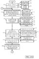
- FIGS. 4A and 4B show a flow diagram illustrating one example of the operation of threshold generation system 109 and control system 108.
- Trigger detection component 286 first detects trigger criteria for setting a threshold that can be used by control system 108. This is indicated by block 302 in FIG. 4 .
- the trigger criteria can be any of a variety of different types of criteria.
- the thresholds can be calculated on a periodic basis or on an otherwise intermittent basis.
- the passage of a time period 304 may trigger detection component 286 to indicate that the triggering criteria are present.
- the processing can be done continuously, on a rolling basis. Therefore, the triggering criteria may simply be that the mobile machine is operating. Continuous processing is indicated by block 306.
- the triggering criteria can be a wide variety of other triggering criteria 308 as well.
- signal value recording component 284 illustratively receives sensor signals or measurement signals that are indicative of a performance metric for machine 100, and records discrete signal values for that signal. This is indicated by block 310.
- FIG. 5 shows one example of a sensor signal value.
- the signal shown in FIG. 5 represents measured grain loss.
- FIG. 5 shows that the signal value ranges between approximately 2 and approximately 8, over a 4,000 second time period. Because the signal represents grain loss, the lower the signal, the better combine 100 is performing.
- signal value recording component 284 records the signal, or records individual or discrete values for the signal, over the given time period. Recording the signal for a time period is indicated by block 312. Alternatively, the signal can be continuously recorded, as indicated by block 314. The signal can be recorded in other was as well, and this is indicated by block 316.
- Discrete value aggregation component 288 then aggregates the discrete values that are recorded for the input signal into categories. This is indicated by block 318 in FIG. 4 .
- the signals are aggregated into categories on a rolling basis. Therefore, the current signals that are aggregated into the categories may replace older signals that were previously added into the categories. This is indicated by block 320.
- the signals can be aggregated for a discrete time period, where no rolling information is considered. This is indicated by block 322.
- the aggregation can be performed using histograms 324. That is, the signal values can be placed into a histogram. Thus, the range of values is divided into consecutive bins of non-overlapping intervals of the measured variable and then a count of the number of discrete signal values recorded over the given time period that fall into each bin is represented by the histogram.
- the histogram can also be normalized so that each bar in the histogram shows a proportion of values that fall into each bin, with the sum of all bins (or heights) equaling 1. This shows the relative frequencies of the values falling into each bin.
- the signal values can be aggregated into categories using a digital filter 326, or in other ways 328 as well.
- FIG. 6 shows one example of a histogram that is generated from the discrete signal values captured for the signal shown in FIG. 5 . It can be seen that the histogram divides the range of signal values into consecutive bins of non-overlapping intervals of the measured signal, with each interval being approximately 0.14 signal value units (e.g., if the signal value is measured in Volts, then each bin represents 0.14 Volts). The number of occurrences in each bin ranges from 0 to approximately 250. The spread of the histogram along the signal value axis represents the signal noise.
- Threshold identification system 290 then identifies a threshold signal value, (based upon the spread in the aggregated signal values) and outputs it to control the subsystems of combine 100. This is indicated by block 334.
- the threshold value is identified by using a fixed ratio or other metric relative to the spread of the data (such as one or two standout deviations, etc.). This is indicated by block 329.
- the threshold can be identified in other was as well.
- cumulative distribution function generator 296 generates a function from the histogram shown in FIG. 6 that maps a performance percentile to an actual threshold signal value from the aggregated signal values in the histogram. This is indicated by block 330.
- Function generator 296 can, for instance, integrate over the histogram shown in FIG. 6 to generate the cumulative distribution function. One example of this is shown in FIG. 7 .
- the cumulative distribution function f(x) on the y axis is an integral of the values in the histogram shown in FIG. 6 . It also maps the values of the cumulative distribution function on the y axis to actual signal values (or control thresholds) on the x axis.
- quantile function application component 298 first selects a value on the y axis that represents a performance percentile (or performance target) and then identifies a corresponding threshold value on the x axis, and outputs that value. Selecting the performance percentile is indicated by block 332. in FIG. 4 .
- FIG. 8 shows one example of this.
- the performance percentile (or the value of the cumulative distribution function on the y axis) is selected as 0.8. This maps to a signal value on the x axis of approximately 5.8. Thus, system 109 provides the value of 5.8 as the threshold value for the given input signal that measures grain loss. This signal is provided to control system 108.
- the threshold value can be identified in other ways as well. This is indicated by block 335.
- Control system 108 then generates one or more control signals based upon the identified threshold value. This is indicated by block 336. It uses the control signal to control one or more subsystems to meet the identified threshold value (which corresponds to the identified performance target). This is indicated by block 338. It can also output any information that was used, along with the threshold value itself, to other systems. This is indicated by block 340. For instance, it can output the information to the user interface system 116 to surface it for the user. This is indicated by block 342. It can output the information to remote systems 125, using communication component 114. This is indicated by block 344. It can output it in other ways as well. This is indicated by block 346.
- control system 108 By selecting a threshold value (that represents a performance target)) for control system 108, and then allowing control system 108 to control the subsystems 110-112 in order to meet that performance target, control system 108 will continuously drive the control of agricultural machine 100 to improve, until the performance target (the corresponding threshold value) stabilizes. For instance, once the threshold value of 5.8 (which corresponds to a performance target of the 80 th percentile) is set for control system 108, and control system 108 controls subsystems 110-112 to meet that target, then processing may again return to block 302 where a new performance target is calculated.
- a threshold value that represents a performance target
- the signal can again be received and discrete values can be recorded and aggregated into a histogram.
- FIG. 9 shows one example of such a histogram.
- the occurrence of the discrete signal values that are above the threshold signal (and hence those signal values representing performance that is worse than the performance target) is significantly reduced over the occurrence of the values shown in FIG. 6 .
- the corresponding threshold signal value will now be less than 5.8. In the example shown in FIG. 9 , it may be slightly less than 5.0.
- control system 108 This is again output to the control system 108 as the new control threshold, and control system 108 continues to control the controlled subsystems 110-112 in order to meet the new, and better, performance target.
- this process allows control system 108 to continuously improve the operation of agricultural machine 100, with respect to the performance targets identified, until threshold values stabilize. That is, it continues to improve the operation of agricultural machine 100 until the performance targets no longer decrease or no longer decrease by a threshold amount, from one iteration to the next.
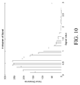
- FIG. 10 is a histogram showing one example of the signal values after system 109 has iterated through this process a number of times. It can be seen that the signal values have been significantly reduced, and thus the performance of machine 100 with respect to those signal values (e.g., with respect to measured grain loss) has been significantly increased. Thus, by iterating through the process of setting new performance targets for each signal, and then controlling the subsystems to meet those new performance targets, the performance of the machine continues until those performance targets stabilize.
- the signal that is indicative of the performance target is a grain loss signal. Therefore, the lower the signal, the better the performance of machine 100 with respect to grain loss.
- the signal may be a signal in which improvement is represented by higher number, instead of a lower number.
- control system 108 will drive the performance of machine 100 so that the signal levels continue to increase (and thus represent improved performance) in the same way that the signal described above continued to decrease (and thus represent improved performance) until the signal stabilizes.
- Continuing to iterate through setting new performance targets (or threshold levels) until they stabilize is indicated by block 350 in FIG. 4 .
- processors and servers include computer processors with associated memory and timing circuitry, not separately shown. They are functional parts of the systems or devices to which they belong and are activated by, and facilitate the functionality of the other components or items in those systems.
- the user actuatable input mechanisms can be text boxes, check boxes, icons, links, drop-down menus, search boxes, etc. They can also be actuated in a wide variety of different ways. For instance, they can be actuated using a point and click device (such as a track ball or mouse). They can be actuated using hardware buttons, switches, a joystick or keyboard, thumb switches or thumb pads, etc. They can also be actuated using a virtual keyboard or other virtual actuators. In addition, where the screen on which they are displayed is a touch sensitive screen, they can be actuated using touch gestures. Also, where the device that displays them has speech recognition components, they can be actuated using speech commands.
- a number of data stores have also been discussed. It will be noted they can each be broken into multiple data stores. All can be local to the systems accessing them, all can be remote, or some can be local while others are remote. All of these configurations are contemplated herein.
- the figures show a number of blocks with functionality ascribed to each block. It will be noted that fewer blocks can be used so the functionality is performed by fewer components. Also, more blocks can be used with the functionality distributed among more components.
- information and performance targets can be output to the cloud or another remote server environment.
- FIG. 1 can be disposed on a wide variety of different devices. Some of those devices include servers, desktop computers, laptop computers, tablet computers, or other mobile devices, such as palm top computers, cell phones, smart phones, multimedia players, personal digital assistants, etc.
- FIG. 11 is a simplified block diagram of one illustrative example of a handheld or mobile computing device that can be used as a user's or client's hand held device 16, in which the present system (or parts of it) can be deployed.
- a mobile device can be deployed in the operator compartment of agricultural machine 100 for use in generating, processing, or displaying the performance targets and other data.
- FIGS. 12-13 are examples of handheld or mobile devices.
- FIG. 11 provides a general block diagram of the components of a client device 16 that can run some components shown in FIG. 1 , that interacts with them, or both.
- a communications link 13 is provided that allows the handheld device to communicate with other computing devices and under some embodiments provides a channel for receiving information automatically, such as by scanning. Examples of communications link 13 include allowing communication though one or more communication protocols, such as wireless services used to provide cellular access to a network, as well as protocols that provide local wireless connections to networks.
- SD Secure Digital
- Interface 15 and communication links 13 communicate with a processor 17 (which can also embody processor 120 from FIG. 1 ) along a bus 19 that is also connected to memory 21 and input/output (I/O) components 23, as well as clock 25 and location system 27.
- processor 17 which can also embody processor 120 from FIG. 1
- bus 19 that is also connected to memory 21 and input/output (I/O) components 23, as well as clock 25 and location system 27.
- I/O components 23 are provided to facilitate input and output operations.
- I/O components 23 for various embodiments of the device 16 can include input components such as buttons, touch sensors, optical sensors, microphones, touch screens, proximity sensors, accelerometers, orientation sensors and output components such as a display device, a speaker, and or a printer port.
- Other I/O components 23 can be used as well.
- Clock 25 illustratively comprises a real time clock component that outputs a time and date. It can also, illustratively, provide timing functions for processor 17.
- Location system 27 illustratively includes a component that outputs a current geographical location of device 16. This can include, for instance, a global positioning system (GPS) receiver, a LORAN system, a dead reckoning system, a cellular triangulation system, or other positioning system. It can also include, for example, mapping software or navigation software that generates desired maps, navigation routes and other geographic functions.
- GPS global positioning system
- Memory 21 stores operating system 29, network settings 31, applications 33, application configuration settings 35, data store 37, communication drivers 39, and communication configuration settings 41.
- Memory 21 can include all types of tangible volatile and non-volatile computer-readable memory devices. It can also include computer storage media (described below).
- Memory 21 stores computer readable instructions that, when executed by processor 17, cause the processor to perform computer-implemented steps or functions according to the instructions. Processor 17 can be activated by other components to facilitate their functionality as well.
- FIG. 12 shows one embodiment in which device 16 is a tablet computer 600.
- computer 600 is shown with user interface display screen 602.
- Screen 602 can be a touch screen or a pen-enabled interface that receives inputs from a pen or stylus. It can also use an on-screen virtual keyboard. Of course, it might also be attached to a keyboard or other user input device through a suitable attachment mechanism, such as a wireless link or USB port, for instance.
- Computer 600 can also illustratively receive voice inputs as well.
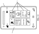
- FIG. 13 shows that the device can be a smart phone 71.
- Smart phone 71 has a touch sensitive display 73 that displays icons or tiles or other user input mechanisms 75. Mechanisms 75 can be used by a user to run applications, make calls, perform data transfer operations, etc.
- smart phone 71 is built on a mobile operating system and offers more advanced computing capability and connectivity than a feature phone.
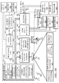
- FIG. 14 is one example of a computing environment in which elements of FIG. 1 , or parts of it, (for example) can be deployed.
- an example system for implementing some embodiments includes a general-purpose computing device in the form of a computer 810.
- Components of computer 810 may include, but are not limited to, a processing unit 820 (which can comprise processor 120), a system memory 830, and a system bus 821 that couples various system components including the system memory to the processing unit 820.
- the system bus 821 may be any of several types of bus structures including a memory bus or memory controller, a peripheral bus, and a local bus using any of a variety of bus architectures. Memory and programs described with respect to FIG. 1 can be deployed in corresponding portions of FIG. 14 .
- Computer 810 typically includes a variety of computer readable media.
- Computer readable media can be any available media that can be accessed by computer 810 and includes both volatile and nonvolatile media, removable and non-removable media.
- Computer readable media may comprise computer storage media and communication media.
- Computer storage media is different from, and does not include, a modulated data signal or carrier wave. It includes hardware storage media including both volatile and nonvolatile, removable and non-removable media implemented in any method or technology for storage of information such as computer readable instructions, data structures, program modules or other data.
- Computer storage media includes, but is not limited to, RAM, ROM, EEPROM, flash memory or other memory technology, CD-ROM, digital versatile disks (DVD) or other optical disk storage, magnetic cassettes, magnetic tape, magnetic disk storage or other magnetic storage devices, or any other medium which can be used to store the desired information and which can be accessed by computer 810.
- Communication media may embody computer readable instructions, data structures, program modules or other data in a transport mechanism and includes any information delivery media.
- modulated data signal means a signal that has one or more of its characteristics set or changed in such a manner as to encode information in the signal.
- the system memory 830 includes computer storage media in the form of volatile and/or nonvolatile memory such as read only memory (ROM) 831 and random access memory (RAM) 832.
- ROM read only memory
- RAM random access memory
- BIOS basic input/output system 833
- RAM 832 typically contains data and/or program modules that are immediately accessible to and/or presently being operated on by processing unit 820.
- FIG. 14 illustrates operating system 834, application programs 835, other program modules 836, and program data 837.
- the computer 810 may also include other removable/non-removable volatile/nonvolatile computer storage media.
- FIG. 10 illustrates a hard disk drive 841 that reads from or writes to non-removable, nonvolatile magnetic media, an optical disk drive 855, and nonvolatile optical disk 856.
- the hard disk drive 841 is typically connected to the system bus 821 through a non-removable memory interface such as interface 840, and optical disk drive 855 are typically connected to the system bus 821 by a removable memory interface, such as interface 850.
- the functionality described herein can be performed, at least in part, by one or more hardware logic components.
- illustrative types of hardware logic components include Field-programmable Gate Arrays (FPGAs), Application-specific Integrated Circuits (e.g., ASICs), Application-specific Standard Products (e.g., ASSPs), System-on-a-chip systems (SOCs), Complex Programmable Logic Devices (CPLDs), etc.
- drives and their associated computer storage media discussed above and illustrated in FIG. 14 provide storage of computer readable instructions, data structures, program modules and other data for the computer 810.
- hard disk drive 841 is illustrated as storing operating system 844, application programs 845, other program modules 846, and program data 847. Note that these components can either be the same as or different from operating system 834, application programs 835, other program modules 836, and program data 837.
- a user may enter commands and information into the computer 810 through input devices such as a keyboard 862, a microphone 863, and a pointing device 861, such as a mouse, trackball or touch pad.
- Other input devices may include a joystick, game pad, satellite dish, scanner, or the like.
- a visual display 891 or other type of display device is also connected to the system bus 821 via an interface, such as a video interface 890.
- computers may also include other peripheral output devices such as speakers 897 and printer 896, which may be connected through an output peripheral interface 895.
- the computer 810 is operated in a networked environment using logical connections (such as a local area network - LAN, or wide area network WAN) to one or more remote computers, such as a remote computer 880.
- logical connections such as a local area network - LAN, or wide area network WAN
- remote computers such as a remote computer 880.
- the computer 810 When used in a LAN networking environment, the computer 810 is connected to the LAN 871 through a network interface or adapter 870. When used in a WAN networking environment, the computer 810 typically includes a modem 872 or other means for establishing communications over the WAN 873, such as the Internet. In a networked environment, program modules may be stored in a remote memory storage device. FIG. 14 illustrates, for example, that remote application programs 885 can reside on remote computer 880.
Landscapes
- Engineering & Computer Science (AREA)
- Automation & Control Theory (AREA)
- Physics & Mathematics (AREA)
- General Physics & Mathematics (AREA)
- Transportation (AREA)
- Mechanical Engineering (AREA)
- Remote Sensing (AREA)
- Radar, Positioning & Navigation (AREA)
- Aviation & Aerospace Engineering (AREA)
- Chemical & Material Sciences (AREA)
- Environmental Sciences (AREA)
- Combustion & Propulsion (AREA)
- Life Sciences & Earth Sciences (AREA)
- Manufacturing & Machinery (AREA)
- Human Computer Interaction (AREA)
- Management, Administration, Business Operations System, And Electronic Commerce (AREA)
- Testing And Monitoring For Control Systems (AREA)
- Mobile Radio Communication Systems (AREA)
- Navigation (AREA)
- Harvester Elements (AREA)
Applications Claiming Priority (1)
| Application Number | Priority Date | Filing Date | Title |
|---|---|---|---|
| US14/868,132 US10234837B2 (en) | 2015-09-28 | 2015-09-28 | Adaptive performance targets for controlling a mobile machine |
Publications (2)
| Publication Number | Publication Date |
|---|---|
| EP3147741A1 true EP3147741A1 (fr) | 2017-03-29 |
| EP3147741B1 EP3147741B1 (fr) | 2019-06-19 |
Family
ID=57256033
Family Applications (1)
| Application Number | Title | Priority Date | Filing Date |
|---|---|---|---|
| EP16184273.7A Active EP3147741B1 (fr) | 2015-09-28 | 2016-08-16 | Cibles de performance adaptatives pour commander une machine mobile |
Country Status (6)
| Country | Link |
|---|---|
| US (1) | US10234837B2 (fr) |
| EP (1) | EP3147741B1 (fr) |
| CN (1) | CN106557044B (fr) |
| AR (1) | AR105830A1 (fr) |
| BR (1) | BR102016020384B1 (fr) |
| RU (1) | RU2725806C2 (fr) |
Families Citing this family (12)
| Publication number | Priority date | Publication date | Assignee | Title |
|---|---|---|---|---|
| US10554170B2 (en) | 2015-10-08 | 2020-02-04 | Con Edison Battery Storage, Llc | Photovoltaic energy system with solar intensity prediction |
| GB201820715D0 (en) * | 2018-12-19 | 2019-01-30 | Agco Int Gmbh | Combine harvester and method of controlling such |
| CN114746819B (zh) * | 2019-11-19 | 2025-10-03 | 三菱电机株式会社 | 劣化判定装置、阈值决定装置、阈值决定方法及记录介质 |
| CN113298670A (zh) * | 2020-02-06 | 2021-08-24 | 迪尔公司 | 预测机器特性图生成和控制系统 |
| US12016257B2 (en) | 2020-02-19 | 2024-06-25 | Sabanto, Inc. | Methods for detecting and clearing debris from planter gauge wheels, closing wheels and seed tubes |
| US11554791B2 (en) * | 2020-03-06 | 2023-01-17 | Caterpillar Paving Products Inc. | Test system and method for autonomous machines |
| US12259703B2 (en) | 2020-03-25 | 2025-03-25 | Fanuc Corporation | Control device |
| IT202000006478A1 (it) | 2020-03-27 | 2021-09-27 | Kverneland Group Ravenna Srl | Metodo per controllare operazioni di avvolgimento |
| US12461083B2 (en) | 2020-08-03 | 2025-11-04 | Sabanto, Inc. | Methods for improved agricultural procedures |
| US11580827B2 (en) * | 2020-10-08 | 2023-02-14 | Baker Hughes Oilfield Operations Llc | Signal displays |
| CN113753344A (zh) * | 2021-09-01 | 2021-12-07 | 普林斯顿科技发展(北京)有限公司 | 一种装箱机用自动化控制软件 |
| CN120652853B (zh) * | 2025-08-13 | 2025-10-14 | 哆想(厦门)智能技术有限公司 | 数智化展厅智控数据联动控制方法及系统 |
Citations (2)
| Publication number | Priority date | Publication date | Assignee | Title |
|---|---|---|---|---|
| WO2012045559A1 (fr) * | 2010-10-04 | 2012-04-12 | Agco Sa | Système et procédé de commande d'un tracteur agricole |
| US20150199630A1 (en) * | 2014-01-14 | 2015-07-16 | Deere & Company | Operator performance opportunity analysis |
Family Cites Families (27)
| Publication number | Priority date | Publication date | Assignee | Title |
|---|---|---|---|---|
| US4338669A (en) * | 1980-05-07 | 1982-07-06 | Crane Co. | Modulator for anti-skid braking system |
| DE19506059A1 (de) * | 1995-02-22 | 1996-08-29 | Deere & Co | Verfahren zur automatischen Regelung wenigstens eines Abschnitts der Gutbearbeitung in einer Erntemaschine |
| US5825657A (en) * | 1996-02-23 | 1998-10-20 | Monitoring Technology Corporation | Dynamic, non-uniform clock for resampling and processing machine signals |
| US5878557A (en) * | 1998-04-13 | 1999-03-09 | Deere & Company | Derating the engine of a combine in response to usage |
| US6119442A (en) * | 1999-05-14 | 2000-09-19 | Case Corporation | Combine setting autoadjust with machine vision |
| US6591145B1 (en) * | 2000-09-21 | 2003-07-08 | Bechtel Bwxt Idaho, Llc | Systems and methods for autonomously controlling agricultural machinery |
| US6592453B2 (en) * | 2001-09-27 | 2003-07-15 | Deere & Company | Harvester feedrate control with tilt compensation |
| GB0424737D0 (en) * | 2004-11-09 | 2004-12-08 | Isis Innovation | Method,computer program and signal processing apparatus for determining statistical information of a signal |
| DE102005014278A1 (de) * | 2005-03-24 | 2006-10-05 | Claas Selbstfahrende Erntemaschinen Gmbh | Verfahren zur Ermittlung eines Ziel-Einstellwerts |
| DE102005023256A1 (de) * | 2005-05-20 | 2006-11-23 | Deere & Company, Moline | Überwachungseinrichtung und ein Verfahren zur Überwachung der Funktion der Komponenten einer landwirtschaftlichen Arbeitsmaschine |
| DE102005026159A1 (de) * | 2005-06-06 | 2007-01-25 | Claas Selbstfahrende Erntemaschinen Gmbh | Verfahren zur Steuerung einer Erntemaschine |
| DE102005031426A1 (de) * | 2005-07-04 | 2007-01-18 | Claas Selbstfahrende Erntemaschinen Gmbh | Verfahren und Vorrichtung zur Optimierung von Betriebsparametern einer landwirtschaftlichen Arbeitsmaschine |
| CN101663629B (zh) * | 2007-03-01 | 2012-10-03 | 拉姆伯斯公司 | 用于电子系统的优化电源 |
| JP2009181242A (ja) * | 2008-01-29 | 2009-08-13 | Panasonic Corp | デジタルpid制御装置 |
| DE102009009767A1 (de) * | 2009-02-20 | 2010-08-26 | Claas Selbstfahrende Erntemaschinen Gmbh | Fahrerassistenzsystem für landwirtschaftliche Arbeitsmaschine |
| US20110084910A1 (en) * | 2009-10-13 | 2011-04-14 | Research In Motion Limited | Portable electronic device including touch-sensitive display and method of controlling same |
| US8469784B1 (en) * | 2010-04-16 | 2013-06-25 | U.S. Department Of Energy | Autonomous grain combine control system |
| KR101614342B1 (ko) * | 2011-07-20 | 2016-04-21 | 얀마 가부시키가이샤 | 콤바인 |
| EP2579112B1 (fr) * | 2011-10-06 | 2014-01-01 | Siemens Aktiengesellschaft | Dispositif de régulation |
| EP2626670B1 (fr) * | 2012-02-09 | 2016-05-25 | SICK STEGMANN GmbH | Procédé pour obtenir des informations sur la phase d'un système en rotation |
| EP2994803A1 (fr) * | 2013-05-10 | 2016-03-16 | CNH Industrial America LLC | Architecture de commande pour un systeme multi-robot |
| US9797794B2 (en) * | 2013-06-14 | 2017-10-24 | Invensys Systems, Inc. | Inferential sensing engine |
| JP2016540230A (ja) * | 2013-09-20 | 2016-12-22 | キャタピラー インコーポレイテッドCaterpillar Incorporated | 測位システム |
| US10371561B2 (en) * | 2013-11-01 | 2019-08-06 | Iowa State University Research Foundation, Inc. | Yield measurement and base cutter height control systems for a harvester |
| US9689336B2 (en) * | 2014-11-10 | 2017-06-27 | Caterpillar Inc. | Engine system utilizing modal weighted engine optimization |
| CN104679041B (zh) * | 2015-02-14 | 2017-10-27 | 雷沃重工股份有限公司 | 一种收割机作业负荷控制系统及方法 |
| US10281905B2 (en) * | 2015-09-23 | 2019-05-07 | Deere & Company | Control system for agricultural equipment |
-
2015
- 2015-09-28 US US14/868,132 patent/US10234837B2/en active Active
-
2016
- 2016-08-16 EP EP16184273.7A patent/EP3147741B1/fr active Active
- 2016-08-26 RU RU2016134916A patent/RU2725806C2/ru active
- 2016-08-26 AR ARP160102610A patent/AR105830A1/es active IP Right Grant
- 2016-08-31 CN CN201610793571.4A patent/CN106557044B/zh active Active
- 2016-09-02 BR BR102016020384-8A patent/BR102016020384B1/pt active IP Right Grant
Patent Citations (2)
| Publication number | Priority date | Publication date | Assignee | Title |
|---|---|---|---|---|
| WO2012045559A1 (fr) * | 2010-10-04 | 2012-04-12 | Agco Sa | Système et procédé de commande d'un tracteur agricole |
| US20150199630A1 (en) * | 2014-01-14 | 2015-07-16 | Deere & Company | Operator performance opportunity analysis |
Also Published As
| Publication number | Publication date |
|---|---|
| US20170090445A1 (en) | 2017-03-30 |
| BR102016020384A2 (pt) | 2017-04-04 |
| BR102016020384B1 (pt) | 2022-01-18 |
| CN106557044B (zh) | 2021-02-02 |
| RU2016134916A (ru) | 2018-03-01 |
| EP3147741B1 (fr) | 2019-06-19 |
| US10234837B2 (en) | 2019-03-19 |
| CN106557044A (zh) | 2017-04-05 |
| RU2016134916A3 (fr) | 2020-04-27 |
| RU2725806C2 (ru) | 2020-07-06 |
| AR105830A1 (es) | 2017-11-15 |
Similar Documents
| Publication | Publication Date | Title |
|---|---|---|
| EP3147741B1 (fr) | Cibles de performance adaptatives pour commander une machine mobile | |
| US20250212725A1 (en) | Adaptive forward-looking characteristic conversion and machine control during crop harvesting operations | |
| CN111802061B (zh) | 使用实时模型的机械控制 | |
| US12495733B2 (en) | Predictive map and machine control | |
| EP3150049B1 (fr) | Commande probabiliste d'une machine agricole | |
| US11240961B2 (en) | Controlling a harvesting machine based on a geo-spatial representation indicating where the harvesting machine is likely to reach capacity | |
| CN107015519B (zh) | 移动机器以及农业收割机 | |
| US20200323133A1 (en) | Machine control using real-time model | |
| US9560802B1 (en) | Tailings plug reduction | |
| US10481628B2 (en) | Surfacing of subsystem power consumption on an agricultural machine | |
| EP3315003A1 (fr) | Commande d'un véhicule agricole basée sur des variables détectées filtrées par différents filtres | |
| EP3146824B1 (fr) | Système de commande pour un équipement agricole | |
| EP3456172B1 (fr) | Système d'assistance au conducteur sur une moissonneuse-batteuse |
Legal Events
| Date | Code | Title | Description |
|---|---|---|---|
| PUAI | Public reference made under article 153(3) epc to a published international application that has entered the european phase |
Free format text: ORIGINAL CODE: 0009012 |
|
| STAA | Information on the status of an ep patent application or granted ep patent |
Free format text: STATUS: THE APPLICATION HAS BEEN PUBLISHED |
|
| AK | Designated contracting states |
Kind code of ref document: A1 Designated state(s): AL AT BE BG CH CY CZ DE DK EE ES FI FR GB GR HR HU IE IS IT LI LT LU LV MC MK MT NL NO PL PT RO RS SE SI SK SM TR |
|
| AX | Request for extension of the european patent |
Extension state: BA ME |
|
| STAA | Information on the status of an ep patent application or granted ep patent |
Free format text: STATUS: REQUEST FOR EXAMINATION WAS MADE |
|
| 17P | Request for examination filed |
Effective date: 20170929 |
|
| RBV | Designated contracting states (corrected) |
Designated state(s): AL AT BE BG CH CY CZ DE DK EE ES FI FR GB GR HR HU IE IS IT LI LT LU LV MC MK MT NL NO PL PT RO RS SE SI SK SM TR |
|
| STAA | Information on the status of an ep patent application or granted ep patent |
Free format text: STATUS: EXAMINATION IS IN PROGRESS |
|
| RIC1 | Information provided on ipc code assigned before grant |
Ipc: G05B 19/4155 20060101ALI20181001BHEP Ipc: G05D 1/02 20060101ALI20181001BHEP Ipc: A01D 41/127 20060101AFI20181001BHEP Ipc: G05B 19/042 20060101ALI20181001BHEP |
|
| 17Q | First examination report despatched |
Effective date: 20181029 |
|
| REG | Reference to a national code |
Ref country code: DE Ref legal event code: R079 Ref document number: 602016015433 Country of ref document: DE Free format text: PREVIOUS MAIN CLASS: G05D0001020000 Ipc: B60W0010300000 |
|
| GRAP | Despatch of communication of intention to grant a patent |
Free format text: ORIGINAL CODE: EPIDOSNIGR1 |
|
| STAA | Information on the status of an ep patent application or granted ep patent |
Free format text: STATUS: GRANT OF PATENT IS INTENDED |
|
| RIC1 | Information provided on ipc code assigned before grant |
Ipc: A01D 41/127 20060101ALI20181210BHEP Ipc: B60W 50/00 20060101ALI20181210BHEP Ipc: B60W 30/00 20060101ALI20181210BHEP Ipc: B60W 10/30 20060101AFI20181210BHEP Ipc: G05B 19/042 20060101ALI20181210BHEP |
|
| INTG | Intention to grant announced |
Effective date: 20190108 |
|
| GRAS | Grant fee paid |
Free format text: ORIGINAL CODE: EPIDOSNIGR3 |
|
| GRAA | (expected) grant |
Free format text: ORIGINAL CODE: 0009210 |
|
| STAA | Information on the status of an ep patent application or granted ep patent |
Free format text: STATUS: THE PATENT HAS BEEN GRANTED |
|
| AK | Designated contracting states |
Kind code of ref document: B1 Designated state(s): AL AT BE BG CH CY CZ DE DK EE ES FI FR GB GR HR HU IE IS IT LI LT LU LV MC MK MT NL NO PL PT RO RS SE SI SK SM TR |
|
| REG | Reference to a national code |
Ref country code: GB Ref legal event code: FG4D |
|
| REG | Reference to a national code |
Ref country code: CH Ref legal event code: EP |
|
| REG | Reference to a national code |
Ref country code: IE Ref legal event code: FG4D |
|
| REG | Reference to a national code |
Ref country code: DE Ref legal event code: R096 Ref document number: 602016015433 Country of ref document: DE |
|
| REG | Reference to a national code |
Ref country code: AT Ref legal event code: REF Ref document number: 1145104 Country of ref document: AT Kind code of ref document: T Effective date: 20190715 |
|
| REG | Reference to a national code |
Ref country code: NL Ref legal event code: MP Effective date: 20190619 |
|
| PG25 | Lapsed in a contracting state [announced via postgrant information from national office to epo] |
Ref country code: AL Free format text: LAPSE BECAUSE OF FAILURE TO SUBMIT A TRANSLATION OF THE DESCRIPTION OR TO PAY THE FEE WITHIN THE PRESCRIBED TIME-LIMIT Effective date: 20190619 Ref country code: LT Free format text: LAPSE BECAUSE OF FAILURE TO SUBMIT A TRANSLATION OF THE DESCRIPTION OR TO PAY THE FEE WITHIN THE PRESCRIBED TIME-LIMIT Effective date: 20190619 Ref country code: SE Free format text: LAPSE BECAUSE OF FAILURE TO SUBMIT A TRANSLATION OF THE DESCRIPTION OR TO PAY THE FEE WITHIN THE PRESCRIBED TIME-LIMIT Effective date: 20190619 Ref country code: FI Free format text: LAPSE BECAUSE OF FAILURE TO SUBMIT A TRANSLATION OF THE DESCRIPTION OR TO PAY THE FEE WITHIN THE PRESCRIBED TIME-LIMIT Effective date: 20190619 Ref country code: NO Free format text: LAPSE BECAUSE OF FAILURE TO SUBMIT A TRANSLATION OF THE DESCRIPTION OR TO PAY THE FEE WITHIN THE PRESCRIBED TIME-LIMIT Effective date: 20190919 Ref country code: HR Free format text: LAPSE BECAUSE OF FAILURE TO SUBMIT A TRANSLATION OF THE DESCRIPTION OR TO PAY THE FEE WITHIN THE PRESCRIBED TIME-LIMIT Effective date: 20190619 |
|
| REG | Reference to a national code |
Ref country code: LT Ref legal event code: MG4D |
|
| PG25 | Lapsed in a contracting state [announced via postgrant information from national office to epo] |
Ref country code: LV Free format text: LAPSE BECAUSE OF FAILURE TO SUBMIT A TRANSLATION OF THE DESCRIPTION OR TO PAY THE FEE WITHIN THE PRESCRIBED TIME-LIMIT Effective date: 20190619 Ref country code: BG Free format text: LAPSE BECAUSE OF FAILURE TO SUBMIT A TRANSLATION OF THE DESCRIPTION OR TO PAY THE FEE WITHIN THE PRESCRIBED TIME-LIMIT Effective date: 20190919 Ref country code: GR Free format text: LAPSE BECAUSE OF FAILURE TO SUBMIT A TRANSLATION OF THE DESCRIPTION OR TO PAY THE FEE WITHIN THE PRESCRIBED TIME-LIMIT Effective date: 20190920 Ref country code: RS Free format text: LAPSE BECAUSE OF FAILURE TO SUBMIT A TRANSLATION OF THE DESCRIPTION OR TO PAY THE FEE WITHIN THE PRESCRIBED TIME-LIMIT Effective date: 20190619 |
|
| REG | Reference to a national code |
Ref country code: AT Ref legal event code: MK05 Ref document number: 1145104 Country of ref document: AT Kind code of ref document: T Effective date: 20190619 |
|
| PG25 | Lapsed in a contracting state [announced via postgrant information from national office to epo] |
Ref country code: RO Free format text: LAPSE BECAUSE OF FAILURE TO SUBMIT A TRANSLATION OF THE DESCRIPTION OR TO PAY THE FEE WITHIN THE PRESCRIBED TIME-LIMIT Effective date: 20190619 Ref country code: AT Free format text: LAPSE BECAUSE OF FAILURE TO SUBMIT A TRANSLATION OF THE DESCRIPTION OR TO PAY THE FEE WITHIN THE PRESCRIBED TIME-LIMIT Effective date: 20190619 Ref country code: CZ Free format text: LAPSE BECAUSE OF FAILURE TO SUBMIT A TRANSLATION OF THE DESCRIPTION OR TO PAY THE FEE WITHIN THE PRESCRIBED TIME-LIMIT Effective date: 20190619 Ref country code: NL Free format text: LAPSE BECAUSE OF FAILURE TO SUBMIT A TRANSLATION OF THE DESCRIPTION OR TO PAY THE FEE WITHIN THE PRESCRIBED TIME-LIMIT Effective date: 20190619 Ref country code: EE Free format text: LAPSE BECAUSE OF FAILURE TO SUBMIT A TRANSLATION OF THE DESCRIPTION OR TO PAY THE FEE WITHIN THE PRESCRIBED TIME-LIMIT Effective date: 20190619 Ref country code: PT Free format text: LAPSE BECAUSE OF FAILURE TO SUBMIT A TRANSLATION OF THE DESCRIPTION OR TO PAY THE FEE WITHIN THE PRESCRIBED TIME-LIMIT Effective date: 20191021 Ref country code: SK Free format text: LAPSE BECAUSE OF FAILURE TO SUBMIT A TRANSLATION OF THE DESCRIPTION OR TO PAY THE FEE WITHIN THE PRESCRIBED TIME-LIMIT Effective date: 20190619 |
|
| PG25 | Lapsed in a contracting state [announced via postgrant information from national office to epo] |
Ref country code: ES Free format text: LAPSE BECAUSE OF FAILURE TO SUBMIT A TRANSLATION OF THE DESCRIPTION OR TO PAY THE FEE WITHIN THE PRESCRIBED TIME-LIMIT Effective date: 20190619 Ref country code: IS Free format text: LAPSE BECAUSE OF FAILURE TO SUBMIT A TRANSLATION OF THE DESCRIPTION OR TO PAY THE FEE WITHIN THE PRESCRIBED TIME-LIMIT Effective date: 20191019 Ref country code: SM Free format text: LAPSE BECAUSE OF FAILURE TO SUBMIT A TRANSLATION OF THE DESCRIPTION OR TO PAY THE FEE WITHIN THE PRESCRIBED TIME-LIMIT Effective date: 20190619 |
|
| PG25 | Lapsed in a contracting state [announced via postgrant information from national office to epo] |
Ref country code: TR Free format text: LAPSE BECAUSE OF FAILURE TO SUBMIT A TRANSLATION OF THE DESCRIPTION OR TO PAY THE FEE WITHIN THE PRESCRIBED TIME-LIMIT Effective date: 20190619 |
|
| PG25 | Lapsed in a contracting state [announced via postgrant information from national office to epo] |
Ref country code: DK Free format text: LAPSE BECAUSE OF FAILURE TO SUBMIT A TRANSLATION OF THE DESCRIPTION OR TO PAY THE FEE WITHIN THE PRESCRIBED TIME-LIMIT Effective date: 20190619 Ref country code: PL Free format text: LAPSE BECAUSE OF FAILURE TO SUBMIT A TRANSLATION OF THE DESCRIPTION OR TO PAY THE FEE WITHIN THE PRESCRIBED TIME-LIMIT Effective date: 20190619 |
|
| PG25 | Lapsed in a contracting state [announced via postgrant information from national office to epo] |
Ref country code: CH Free format text: LAPSE BECAUSE OF NON-PAYMENT OF DUE FEES Effective date: 20190831 Ref country code: MC Free format text: LAPSE BECAUSE OF FAILURE TO SUBMIT A TRANSLATION OF THE DESCRIPTION OR TO PAY THE FEE WITHIN THE PRESCRIBED TIME-LIMIT Effective date: 20190619 Ref country code: LI Free format text: LAPSE BECAUSE OF NON-PAYMENT OF DUE FEES Effective date: 20190831 Ref country code: IS Free format text: LAPSE BECAUSE OF FAILURE TO SUBMIT A TRANSLATION OF THE DESCRIPTION OR TO PAY THE FEE WITHIN THE PRESCRIBED TIME-LIMIT Effective date: 20200224 Ref country code: LU Free format text: LAPSE BECAUSE OF NON-PAYMENT OF DUE FEES Effective date: 20190816 |
|
| REG | Reference to a national code |
Ref country code: DE Ref legal event code: R097 Ref document number: 602016015433 Country of ref document: DE |
|
| PLBE | No opposition filed within time limit |
Free format text: ORIGINAL CODE: 0009261 |
|
| STAA | Information on the status of an ep patent application or granted ep patent |
Free format text: STATUS: NO OPPOSITION FILED WITHIN TIME LIMIT |
|
| PG2D | Information on lapse in contracting state deleted |
Ref country code: IS |
|
| PG25 | Lapsed in a contracting state [announced via postgrant information from national office to epo] |
Ref country code: FR Free format text: LAPSE BECAUSE OF NON-PAYMENT OF DUE FEES Effective date: 20190819 Ref country code: IE Free format text: LAPSE BECAUSE OF NON-PAYMENT OF DUE FEES Effective date: 20190816 |
|
| 26N | No opposition filed |
Effective date: 20200603 |
|
| PG25 | Lapsed in a contracting state [announced via postgrant information from national office to epo] |
Ref country code: SI Free format text: LAPSE BECAUSE OF FAILURE TO SUBMIT A TRANSLATION OF THE DESCRIPTION OR TO PAY THE FEE WITHIN THE PRESCRIBED TIME-LIMIT Effective date: 20190619 |
|
| GBPC | Gb: european patent ceased through non-payment of renewal fee |
Effective date: 20200816 |
|
| PG25 | Lapsed in a contracting state [announced via postgrant information from national office to epo] |
Ref country code: CY Free format text: LAPSE BECAUSE OF FAILURE TO SUBMIT A TRANSLATION OF THE DESCRIPTION OR TO PAY THE FEE WITHIN THE PRESCRIBED TIME-LIMIT Effective date: 20190619 |
|
| PG25 | Lapsed in a contracting state [announced via postgrant information from national office to epo] |
Ref country code: HU Free format text: LAPSE BECAUSE OF FAILURE TO SUBMIT A TRANSLATION OF THE DESCRIPTION OR TO PAY THE FEE WITHIN THE PRESCRIBED TIME-LIMIT; INVALID AB INITIO Effective date: 20160816 Ref country code: MT Free format text: LAPSE BECAUSE OF FAILURE TO SUBMIT A TRANSLATION OF THE DESCRIPTION OR TO PAY THE FEE WITHIN THE PRESCRIBED TIME-LIMIT Effective date: 20190619 |
|
| PG25 | Lapsed in a contracting state [announced via postgrant information from national office to epo] |
Ref country code: GB Free format text: LAPSE BECAUSE OF NON-PAYMENT OF DUE FEES Effective date: 20200816 |
|
| PG25 | Lapsed in a contracting state [announced via postgrant information from national office to epo] |
Ref country code: MK Free format text: LAPSE BECAUSE OF FAILURE TO SUBMIT A TRANSLATION OF THE DESCRIPTION OR TO PAY THE FEE WITHIN THE PRESCRIBED TIME-LIMIT Effective date: 20190619 |
|
| PGFP | Annual fee paid to national office [announced via postgrant information from national office to epo] |
Ref country code: IT Payment date: 20220819 Year of fee payment: 7 |
|
| PG25 | Lapsed in a contracting state [announced via postgrant information from national office to epo] |
Ref country code: IT Free format text: LAPSE BECAUSE OF NON-PAYMENT OF DUE FEES Effective date: 20230816 |
|
| PGFP | Annual fee paid to national office [announced via postgrant information from national office to epo] |
Ref country code: DE Payment date: 20250721 Year of fee payment: 10 |
|
| PGFP | Annual fee paid to national office [announced via postgrant information from national office to epo] |
Ref country code: BE Payment date: 20250827 Year of fee payment: 10 |