EP3147742A2 - Steuerungsverfahren und steuerungsvorrichtung für ein ausgeglichenes fahrzeug, computerprogramm und aufzeichnungsmedium - Google Patents
Steuerungsverfahren und steuerungsvorrichtung für ein ausgeglichenes fahrzeug, computerprogramm und aufzeichnungsmedium Download PDFInfo
- Publication number
- EP3147742A2 EP3147742A2 EP16189763.2A EP16189763A EP3147742A2 EP 3147742 A2 EP3147742 A2 EP 3147742A2 EP 16189763 A EP16189763 A EP 16189763A EP 3147742 A2 EP3147742 A2 EP 3147742A2
- Authority
- EP
- European Patent Office
- Prior art keywords
- obstacle
- balanced vehicle
- type
- module
- distance
- Prior art date
- Legal status (The legal status is an assumption and is not a legal conclusion. Google has not performed a legal analysis and makes no representation as to the accuracy of the status listed.)
- Withdrawn
Links
Images


Classifications
-
- G—PHYSICS
- G05—CONTROLLING; REGULATING
- G05D—SYSTEMS FOR CONTROLLING OR REGULATING NON-ELECTRIC VARIABLES
- G05D1/00—Control of position, course, altitude or attitude of land, water, air or space vehicles, e.g. using automatic pilots
- G05D1/02—Control of position or course in two dimensions
-
- B—PERFORMING OPERATIONS; TRANSPORTING
- B60—VEHICLES IN GENERAL
- B60W—CONJOINT CONTROL OF VEHICLE SUB-UNITS OF DIFFERENT TYPE OR DIFFERENT FUNCTION; CONTROL SYSTEMS SPECIALLY ADAPTED FOR HYBRID VEHICLES; ROAD VEHICLE DRIVE CONTROL SYSTEMS FOR PURPOSES NOT RELATED TO THE CONTROL OF A PARTICULAR SUB-UNIT
- B60W30/00—Purposes of road vehicle drive control systems not related to the control of a particular sub-unit, e.g. of systems using conjoint control of vehicle sub-units
- B60W30/08—Active safety systems predicting or avoiding probable or impending collision or attempting to minimise its consequences
- B60W30/095—Predicting travel path or likelihood of collision
- B60W30/0956—Predicting travel path or likelihood of collision the prediction being responsive to traffic or environmental parameters
-
- B—PERFORMING OPERATIONS; TRANSPORTING
- B60—VEHICLES IN GENERAL
- B60R—VEHICLES, VEHICLE FITTINGS, OR VEHICLE PARTS, NOT OTHERWISE PROVIDED FOR
- B60R21/00—Arrangements or fittings on vehicles for protecting or preventing injuries to occupants or pedestrians in case of accidents or other traffic risks
- B60R21/01—Electrical circuits for triggering passive safety arrangements, e.g. airbags, safety belt tighteners, in case of vehicle accidents or impending vehicle accidents
- B60R21/013—Electrical circuits for triggering passive safety arrangements, e.g. airbags, safety belt tighteners, in case of vehicle accidents or impending vehicle accidents including means for detecting collisions, impending collisions or roll-over
- B60R21/0134—Electrical circuits for triggering passive safety arrangements, e.g. airbags, safety belt tighteners, in case of vehicle accidents or impending vehicle accidents including means for detecting collisions, impending collisions or roll-over responsive to imminent contact with an obstacle, e.g. using radar systems
-
- B—PERFORMING OPERATIONS; TRANSPORTING
- B60—VEHICLES IN GENERAL
- B60T—VEHICLE BRAKE CONTROL SYSTEMS OR PARTS THEREOF; BRAKE CONTROL SYSTEMS OR PARTS THEREOF, IN GENERAL; ARRANGEMENT OF BRAKING ELEMENTS ON VEHICLES IN GENERAL; PORTABLE DEVICES FOR PREVENTING UNWANTED MOVEMENT OF VEHICLES; VEHICLE MODIFICATIONS TO FACILITATE COOLING OF BRAKES
- B60T8/00—Arrangements for adjusting wheel-braking force to meet varying vehicular or ground-surface conditions, e.g. limiting or varying distribution of braking force
- B60T8/17—Using electrical or electronic regulation means to control braking
- B60T8/1701—Braking or traction control means specially adapted for particular types of vehicles
- B60T8/1706—Braking or traction control means specially adapted for particular types of vehicles for single-track vehicles, e.g. motorcycles
-
- B—PERFORMING OPERATIONS; TRANSPORTING
- B60—VEHICLES IN GENERAL
- B60T—VEHICLE BRAKE CONTROL SYSTEMS OR PARTS THEREOF; BRAKE CONTROL SYSTEMS OR PARTS THEREOF, IN GENERAL; ARRANGEMENT OF BRAKING ELEMENTS ON VEHICLES IN GENERAL; PORTABLE DEVICES FOR PREVENTING UNWANTED MOVEMENT OF VEHICLES; VEHICLE MODIFICATIONS TO FACILITATE COOLING OF BRAKES
- B60T8/00—Arrangements for adjusting wheel-braking force to meet varying vehicular or ground-surface conditions, e.g. limiting or varying distribution of braking force
- B60T8/32—Arrangements for adjusting wheel-braking force to meet varying vehicular or ground-surface conditions, e.g. limiting or varying distribution of braking force responsive to a speed condition, e.g. acceleration or deceleration
- B60T8/321—Arrangements for adjusting wheel-braking force to meet varying vehicular or ground-surface conditions, e.g. limiting or varying distribution of braking force responsive to a speed condition, e.g. acceleration or deceleration deceleration
- B60T8/3225—Systems specially adapted for single-track vehicles, e.g. motorcycles
-
- B—PERFORMING OPERATIONS; TRANSPORTING
- B60—VEHICLES IN GENERAL
- B60W—CONJOINT CONTROL OF VEHICLE SUB-UNITS OF DIFFERENT TYPE OR DIFFERENT FUNCTION; CONTROL SYSTEMS SPECIALLY ADAPTED FOR HYBRID VEHICLES; ROAD VEHICLE DRIVE CONTROL SYSTEMS FOR PURPOSES NOT RELATED TO THE CONTROL OF A PARTICULAR SUB-UNIT
- B60W10/00—Conjoint control of vehicle sub-units of different type or different function
- B60W10/18—Conjoint control of vehicle sub-units of different type or different function including control of braking systems
-
- B—PERFORMING OPERATIONS; TRANSPORTING
- B62—LAND VEHICLES FOR TRAVELLING OTHERWISE THAN ON RAILS
- B62K—CYCLES; CYCLE FRAMES; CYCLE STEERING DEVICES; RIDER-OPERATED TERMINAL CONTROLS SPECIALLY ADAPTED FOR CYCLES; CYCLE AXLE SUSPENSIONS; CYCLE SIDECARS, FORECARS, OR THE LIKE
- B62K11/00—Motorcycles, engine-assisted cycles or motor scooters with one or two wheels
- B62K11/007—Automatic balancing machines with single main ground engaging wheel or coaxial wheels supporting a rider
-
- B—PERFORMING OPERATIONS; TRANSPORTING
- B62—LAND VEHICLES FOR TRAVELLING OTHERWISE THAN ON RAILS
- B62M—RIDER PROPULSION OF WHEELED VEHICLES OR SLEDGES; POWERED PROPULSION OF SLEDGES OR SINGLE-TRACK CYCLES; TRANSMISSIONS SPECIALLY ADAPTED FOR SUCH VEHICLES
- B62M6/00—Rider propulsion of wheeled vehicles with additional source of power, e.g. combustion engine or electric motor
- B62M6/40—Rider propelled cycles with auxiliary electric motor
- B62M6/45—Control or actuating devices therefor
- B62M6/50—Control or actuating devices therefor characterised by detectors or sensors, or arrangement thereof
-
- G—PHYSICS
- G05—CONTROLLING; REGULATING
- G05D—SYSTEMS FOR CONTROLLING OR REGULATING NON-ELECTRIC VARIABLES
- G05D1/00—Control of position, course, altitude or attitude of land, water, air or space vehicles, e.g. using automatic pilots
- G05D1/02—Control of position or course in two dimensions
- G05D1/021—Control of position or course in two dimensions specially adapted to land vehicles
- G05D1/0231—Control of position or course in two dimensions specially adapted to land vehicles using optical position detecting means
- G05D1/0238—Control of position or course in two dimensions specially adapted to land vehicles using optical position detecting means using obstacle or wall sensors
-
- G—PHYSICS
- G05—CONTROLLING; REGULATING
- G05D—SYSTEMS FOR CONTROLLING OR REGULATING NON-ELECTRIC VARIABLES
- G05D1/00—Control of position, course, altitude or attitude of land, water, air or space vehicles, e.g. using automatic pilots
- G05D1/02—Control of position or course in two dimensions
- G05D1/021—Control of position or course in two dimensions specially adapted to land vehicles
- G05D1/0231—Control of position or course in two dimensions specially adapted to land vehicles using optical position detecting means
- G05D1/0246—Control of position or course in two dimensions specially adapted to land vehicles using optical position detecting means using a video camera in combination with image processing means
-
- G—PHYSICS
- G05—CONTROLLING; REGULATING
- G05D—SYSTEMS FOR CONTROLLING OR REGULATING NON-ELECTRIC VARIABLES
- G05D1/00—Control of position, course, altitude or attitude of land, water, air or space vehicles, e.g. using automatic pilots
- G05D1/08—Control of attitude, i.e. control of roll, pitch, or yaw
- G05D1/0891—Control of attitude, i.e. control of roll, pitch, or yaw specially adapted for land vehicles
-
- G—PHYSICS
- G08—SIGNALLING
- G08G—TRAFFIC CONTROL SYSTEMS
- G08G1/00—Traffic control systems for road vehicles
- G08G1/16—Anti-collision systems
- G08G1/165—Anti-collision systems for passive traffic, e.g. including static obstacles, trees
-
- B—PERFORMING OPERATIONS; TRANSPORTING
- B60—VEHICLES IN GENERAL
- B60W—CONJOINT CONTROL OF VEHICLE SUB-UNITS OF DIFFERENT TYPE OR DIFFERENT FUNCTION; CONTROL SYSTEMS SPECIALLY ADAPTED FOR HYBRID VEHICLES; ROAD VEHICLE DRIVE CONTROL SYSTEMS FOR PURPOSES NOT RELATED TO THE CONTROL OF A PARTICULAR SUB-UNIT
- B60W2554/00—Input parameters relating to objects
-
- B—PERFORMING OPERATIONS; TRANSPORTING
- B60—VEHICLES IN GENERAL
- B60W—CONJOINT CONTROL OF VEHICLE SUB-UNITS OF DIFFERENT TYPE OR DIFFERENT FUNCTION; CONTROL SYSTEMS SPECIALLY ADAPTED FOR HYBRID VEHICLES; ROAD VEHICLE DRIVE CONTROL SYSTEMS FOR PURPOSES NOT RELATED TO THE CONTROL OF A PARTICULAR SUB-UNIT
- B60W2720/00—Output or target parameters relating to overall vehicle dynamics
- B60W2720/10—Longitudinal speed
- B60W2720/106—Longitudinal acceleration
Definitions
- the present invention relates to the field of automatic control, in particular to a control method and apparatus for a balanced vehicle, a computer program and a recording medium.
- a balanced vehicle is also known as an electric balanced vehicle, or as a self-balanced vehicle, and now it is a new kind of short-distance transportation means.
- the balanced vehicle is driven by an internal driving motor to go forward and backward. If there is an obstacle in front of the balanced vehicle, the driver may fall over.
- the present invention provides a control method and apparatus for a balanced vehicle, a computer program and a recording medium.
- the technical solution is as follows:
- a control method for a balanced vehicle comprising:
- the type is impassable obstacle or passable obstacle; the method further comprises:
- identifying the type of an obstacle in front of the balanced vehicle comprises:
- identifying the type of an obstacle in front of the balanced vehicle comprises:
- the method further comprises:
- the method further comprises:
- the method further comprises:
- a control apparatus for a balanced vehicle comprising:
- the type is impassable obstacle or passable obstacle; the apparatus further comprises:
- the identifying module comprises:
- the identifying module comprises:
- the first control module further comprises:
- the first control module further comprises:
- the apparatus further comprises:
- a balanced vehicle comprising:
- the steps of the control method for a balanced vehicle are determined by computer program instructions.
- the invention is also directed to a computer program for executing the steps of a control method for a balanced vehicle as described above when this program is executed by a computer.
- This program can use any programming language and take the form of source code, object code or a code intermediate between source code and object code, such as a partially compiled form, or any other desirable form.
- the invention is also directed to a computer-readable information medium containing instructions of a computer program as described above.
- the information medium can be any entity or device capable of storing the program.
- the information medium can include storage means such as a ROM, for example a CD ROM or a microelectronic circuit ROM, or magnetic storage means, for example a diskette (floppy disk) or a hard disk.
- the information medium can be an integrated circuit in which the program is incorporated, the circuit being adapted to execute the method in question or to be used in its execution.
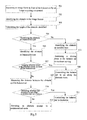
- Fig. 1 is a schematic diagram showing an implementing environment involved in the control method for a balanced vehicle according to an exemplary embodiment of the present invention.
- the implementing environment may be a two-wheel balanced vehicle comprising two parallel wheels 110 and 120, wheel housings 150 and 160, a turning control component 130, a load bearing pedal 140 and obstacle identifying components 170 and 180.
- the turning control component 130 is connected to the load bearing pedal 140 and can be used to control turning of the two-wheel balanced vehicle.
- the turning control component 130 can be implemented through manual control, and can also be implemented through leg control, which is not limited in this embodiment.
- the obstacle identifying components 170 and 180 are used to identify an obstacle in an heading direction of the two-wheel balanced vehicle.
- the obstacle identifying components 170 and 180 can be any distance measuring components capable of identifying the size and distance of an object, such as infrared ray sensing apparatus, ultrasonic wave sensing apparatus and laser range finder, etc.; the obstacle identifying components 170 and 180 can also be any image acquiring components capable of capturing images, such as a camera.
- the obstacle identifying component 170 is provided merely as an example at position 1 of the wheel housing 150
- the obstacle identifying component 180 is provided merely as an example at position 2 of the wheel housing 160.
- the obstacle identifying components 170 and 180 can also be provided at any possible positions of the two-wheel balanced vehicle foreseeable by a person skilled in the art, such as the position where the load bearing pedal 140 is engaged with the turning control component 130, the position for detecting a front left oblique direction of the left wheel and the position for detecting a front right oblique direction of the right wheel, etc..
- the number of the obstacle identifying components 170 and 180 is given as two as an example in this embodiment, and the number of the obstacle identifying component should be at least one. This is not limited in this embodiment.
- the obstacle identifying components 170 and 180 can also have an ability to move in a vertical direction, or, the obstacle identifying components 170 and 180 have an ability to rotate in four directions, namely, up, down, left and right.
- the two-wheel balanced vehicle may also comprise other components, such as a control chip, a storage, and a driving motor, etc. (not shown in the figures).
- the control chip is respectively connected to the driving motor and the above mentioned turning control component 130 and obstacle identifying components 170 and 180, and controls the moving forward, moving backward, stop and turning of the two-wheel balanced vehicle according to the executable instructions stored in the storage. This part of content will not be described expansively in the embodiments of the present invention.
- the above two-wheel balanced vehicle is just an exemplary explanation of an implementing environment involved in the control method for a balanced vehicle provided in the embodiments of the present invention.
- the control method for a balanced vehicle of the present invention can be used not only in two-wheel balanced vehicle, but also in other balanced vehicles identical or similar to the two-wheel balanced vehicle, such as single-wheel balanced vehicle.
- the embodiments of the present invention will not limit this, and the implementing environments thereof will not be shown one by one either.
- Fig. 2 is a flowchart showing a control method for a balanced vehicle according to an exemplary embodiment. As shown in Fig. 2 , the method for a balanced vehicle is used in the balanced vehicle shown in Fig. 1 , and comprises the following steps.
- step 202 the type of an obstacle in front of the balanced vehicle is identified.
- control chip identifies the type of an obstacle in front of any of the wheels by means of an obstacle identifying component.
- the obstacle identifying component comprises: a distance measuring component and/or an image acquiring component.
- step 204 if the type of the obstacle is impassable obstacle, the balanced vehicle is controlled to decelerate.
- the control method for a balanced vehicle identifies the type of the obstacle in front of the balanced vehicle, and controls the balanced vehicle to decelerate if the type of the obstacle is impassable obstacle, thereby solves the problem that the driver is likely to fall over once there is an impassable obstacle in front of the balanced vehicle, and achieves the effects that the balanced vehicle can automatically identify the obstacle, and try to prevent tumbles caused by rapid collision with the obstacle when the obstacle is an impassable obstacle.
- the implementing methods of identifying the type of an obstacle in front of the balanced vehicle in step 202 comprise but are not limited to the following two methods:
- Fig. 3 is a flowchart showing a control method for a balanced vehicle according to another exemplary embodiment. As shown in Fig. 3 , this embodiment illustrates by applying the control method of a balanced vehicle to the two-wheel balanced vehicle shown in Fig. 1 , and the control method for a balanced vehicle comprises the following steps.
- step 301 the height of the obstacle in front of the balanced vehicle is measured by means of a distance measuring component.
- the control chip of the balanced vehicle controls the distance measuring component to transmit a detection signal outwards at intervals at every predetermined time, and the detection signal may be laser, infrared ray and ultrasonic wave, etc..
- a reflected signal will be returned when the detection signal encounters an obstacle.
- the distance measuring component receives the reflected signal, it indicates that there is an obstacle in the front.
- the height of the obstacle is not lower than the height at which the distance measuring component is situated.
- the distance measuring component mounted on the housing of the balanced vehicle is located at a position 5cm away from the ground, if a reflected signal of the detection signal is received, it indicates that there is an obstacle with a height of at least 5cm in front of the balanced vehicle; and if the reflected signal is not received, it indicates that there is no obstacle with a height of over 5cm in front of the balanced vehicle.
- the distance measuring component 30 is capable of moving up and down in a vertical direction on the balanced vehicle.
- the distance measuring component 30 can transmit a detection signal at different positions in the vertical direction.
- the distance measuring component 30 transmits a detection signal at the height h0 from the ground, elevates the height by h1 and transmits the detection signal again after it receives a reflected signal, and elevates the height by h2 and transmits the detection signal once again after it receives the reflected signal again.
- the process repeats, finally, when the height from the ground is h1+h2+...+hn, the distance measuring component 30 does not receive the reflected signal, thereby detects the top of the obstacle 32. At this time, the height of the obstacle measured is h1+h2+...+hn.
- the embodiments of the present invention do not limit the implementing method of measuring the height of the obstacle by means of the distance measuring component.
- the balanced vehicle may also be provided with a plurality of distance measuring components at different positions thereof to measure the height of the obstacle according to whether each of the plurality of distance measuring components has received the reflected signal of the detection signal.
- step 302 whether the height of the obstacle is greater than a predetermined threshold is detected.
- the predetermined threshold is the maximum height of the obstacle that can be passed by the balanced vehicle.
- the predetermined threshold may be 1/x of the height of the tyre or other numerical values, which will not be limited in this embodiment.
- step 303 If the height of the obstacle is greater than the predetermined threshold, turn to step 303; if the height of the obstacle is less than the predetermined threshold, turn to step 304;
- step 303 if the height of the obstacle is greater than the predetermined threshold, the obstacle is identified as impassable type.
- step 305 When the obstacle is impassable type, turn to step 305.
- step 304 if the height of the obstacle is not greater than the predetermined threshold, the obstacle is identified as passable type.
- step 305 whether there is an alternate route in front of the balanced vehicle is judged.
- This step comprises but is not limited to the following two implementing methods:
- the distance measuring component is capable of turning to the left, or, turning to the right, or turning to both the left and the right. Then, the distance measuring component judges whether there is an obstacle in the front left oblique direction or in the front right oblique direction, and if there is no obstacle, there is an alternate route.
- step 306 is entered; and if there is no alternate route, turn to step 307.
- step 306 if there is the alternate route in front of the balanced vehicle, the balanced vehicle is controlled to go along the alternate route.
- control chip controls the balanced vehicle to go along the alternate route.
- step 307 the distance between the obstacle and the balanced vehicle is measured.
- control chip measures the distance between the obstacle in front of any of the wheels and the balanced vehicle by means of the distance measuring component. For example, the control chip acquires the distance by calculation according to the transmission time of the detection signal and the reception time of the reflected signal, in combination with the traveling speed of the balanced vehicle.
- step 308 whether the distance is less than a predetermined distance is detected.
- the control chip detects whether the distance between the obstacle and the balanced vehicle is less than the predetermined distance.
- the predetermined distance is the maximum distance needed when the balanced vehicle turns.
- the predetermined distance may be x times of the diameter of the tyre or other numerical values, which is not limited in this embodiment.
- the predetermined distance is in positive proportion to the current speed of the balanced vehicle, faster the current speed is, larger is the predetermined distance; and slower the current speed is, smaller is the predetermined distance.
- step 309 If the distance is less than the predetermined distance, turn tostep 309 entered; if the distance is greater than the predetermined distance, turn to step 310.
- step 309 if the distance is less than the predetermined distance, the balanced vehicle is controlled to decelerate, and an obstacle alert is provided in a predetermined mode.
- the control chip controls the balanced vehicle to decelerate to stop.
- the control chip controls the balanced vehicle to decelerate and stop before the obstacle; but the situation where the balanced vehicle has collided with the obstacle before it stops completely during the deceleration is also possible to happen.
- control chip also provides the obstacle alert in a predetermined mode, wherein the predetermined mode comprises at least one of playing a alert tone, vibrating a predetermine part of the balanced vehicle, and flickering a signal light.
- the balanced vehicle when identifying that there is an impassable obstacle in front of the balanced vehicle, and when the distance between the impassable obstacle and the balanced vehicle reaches the predetermined distance , the balanced vehicle will make out a beep alert tone.
- step 310 if the distance is less than the predetermined distance, the balanced vehicle is controlled so that it continues moving.
- step 311 if the type of the obstacle is passable obstacle, a driving force is increased to the balanced vehicle so that it continues moving.
- control chip controls the driving motor to increase a driving force to the balanced vehicle to move on.
- the control method for a balanced vehicle identifies the type of the obstacle in front of the balanced vehicle, and controls the balanced vehicle to decelerate if the type of the obstacle is impassable obstacle, thereby solves the problem that the driver is likely to fall over once there is an impassable obstacle in front of the balanced vehicle, and achieves the effect that the balanced vehicle can automatically identify the obstacle and try to prevent tumble caused by rapid collision with the obstacle when the obstacle is an impassable obstacle.
- the control method for a balanced vehicle measures the height and distance of the obstacle by means of the distance measuring component, thereby enables the balanced vehicle to identify the type of the obstacle and decelerate to avoid the obstacle according to the distance between the obstacle and the balanced vehicle.
- the control method of the balanced vehicle provided in this embodiment also judges whether there is an alternate route in front of the balanced vehicle, and automatically controls the balanced vehicle to go along the alternate route if there is an alternate route, thereby achieves the effect of preventing collision between the balanced vehicle and the obstacle without affecting the normal traveling of the balanced vehicle.
- Fig. 5 is a flowchart showing a control method for a balanced vehicle according to an exemplary embodiment. As shown in Fig. 5 , this embodiment illustrates by applying the control method of a balanced vehicle to the implementing environment shown in Fig. 1 , and the method comprises the following steps.
- step 501 an image frame in front of the balanced vehicle is acquired by an image acquiring component.
- the image acquiring component may be mounted on each of the two wheel housings of the balanced vehicle, and may also be mounted at an engagement part of the load bearing pedal and the turning control component.
- the control chip controls the image acquiring component to acquire an image in front of the balanced vehicle to form continuous image frames frame-by-frame.
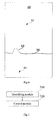
- step 502 the obstacle in the image frames is identified.
- the ground and other objects in the image frames can be determined according to in pixel change in the image frames.
- the control chip obtains an image frame 60 acquired by the image acquiring component, acqurires a first region 62 and a second region 64 by binary process of the image frame 60 according to the color difference , and a road line 66 is formed at an intersection of the first region 62 and second region 64.
- the control chip detects whether the road line 66 has a protrusion 68. If the road line 66 has a protrusion 68, the control chip identifies the protrusion 68 as an obstacle.
- step 503 the height of the obstacle identified is calculated.
- the control chip calculates the height of the obstacle according to the height of the obstacle in the image frame and a predetermined measuring scale, for example, if the predetermined measuring scale is 1:3, when the height of the obstacle in the image frame is 1cm, the height of the obstacle calculated is 3cm. When the obstacle is closer to the balanced vehicle, the height of the obstacle calculated is also closer.
- the balanced vehicle is also provided with a distance measuring component.
- the distance measuring component can measure a distance from the obstacle to the balanced vehicle.
- the control chip first searches for a measuring scale corresponding to the distance, and then calculates the height of the obstacle according to the height of the obstacle in the image frame and the measuring scale corresponding to the distance, for example, if the measuring scale corresponding to the distance is 1:5, when the height of the obstacle in the image frame is 1cm, the height of the obstacle calculated is 5cm.
- the control chip can calculate an actual height of the obstacle according to the protrusion (i.e., the obstacle) in two image frames acquired by the two image acquiring components in combination with the binocular imaging principle.
- this embodiment does not define the way by which the control chip calculates the height of the obstacle.
- step 504 whether the height of the obstacle is greater than a predetermined threshold is detected.
- the control chip detects whether the height of the obstacle calculated is greater than the predetermined threshold.
- the predetermined threshold is the maximum height of the obstacle that can be passed by the balanced vehicle.
- step 505 If the height of the obstacle is greater than the predetermined threshold, turn to step 505; if the height of the obstacle is less than the predetermined threshold, turn to step 506;
- step 505 if the height of the obstacle is greater than the predetermined threshold, the obstacle is identified as impassable type.
- step 506 if the height of the obstacle is less than the predetermined threshold, the obstacle is identified as passable type.
- step 513 When the obstacle is passable type, turn to step 513.
- step 507 when the obstacle is impassable type, whether there is an alternate route in front of the balanced vehicle is judged.
- This step comprises but is not limited to the following three implementing methods:
- the distance measuring component is capable of turning to the left, or, turning to the right, or turning to both the left and the right. Then, the control chip judges whether there is an obstacle in the front left oblique direction or the front right oblique direction by means of the distance measuring component, and if there is no obstacle, there is an alternate route.
- step 508 If there is an alternate route, turn to step 508; and if there is no alternate route, turn to step 509.
- step 508 if there is the alternate route in front of the balanced vehicle, the balanced vehicle is controlled to go along the alternate route.
- control chip controls the balanced vehicle to go along the alternate route.
- step 509 the distance between the obstacle and the balanced vehicle is measured.
- control chip measures the distance between the obstacle in front of any of the wheels and the balanced vehicle by means of the distance measuring component. For example, the control chip acquires the distance by calculation according to the transmission time of the detection signal and the reception time of the reflected signal, in combination with the traveling speed of the balanced vehicle.
- step 510 whether the distance is less than a predetermined distance is detected.
- the control chip detects whether the distance between the obstacle and the balanced vehicle is less than the predetermined distance.
- the predetermined distance is the maximum distance needed when the balanced vehicle turns.
- the predetermined distance may be x times of the diameter of the tyre or other numerical values, and is not defined in this embodiment.
- the predetermined distance is in positive proportion to the current speed of the balanced vehicle, faster the current speed is, larger is the predetermined distance; and slower the current speed is, smaller is the predetermined distance.
- step 511 If the distance is less than the predetermined distance, turn to step 511; if the distance is greater than the predetermined distance, turn to step 512; in step 511, if the distance is less than the predetermined distance, the balanced vehicle is controlled to decelerate, and an obstacle alert is provided in a predetermined mode.
- the control chip controls the balanced vehicle to decelerate to stop.
- the control chip controls the balanced vehicle to decelerate and stop before the obstacle; but the situation where the balanced vehicle has collided with the obstacle before it stops completely during the deceleration is possible to happen.
- control chip also provides the obstacle alert in a predetermined mode, wherein the predetermined mode comprises at least one of playing a alert tone, vibrating a predetermine part of the balanced vehicle, and flickering a signal light.
- the balanced vehicle when it is identified that there is an impassable obstacle in front of the balanced vehicle, and when the impassable obstacle reaches in the predetermined distance from the balanced vehicle, the balanced vehicle will make out a beep alert tone.
- step 512 if the distance is less than the predetermined distance, the balanced vehicle is controlled so that it continues moving.
- step 513 if the type of the obstacle is passable obstacle, a driving force is increased for the balanced vehicle so that it continues moving.
- control chip controls a driving motor to increase the driving force to the balanced vehicle to move on.
- the control method for a balanced vehicle identifies the type of the obstacle in front of the balanced vehicle, and controls the balanced vehicle to decelerate if the type of the obstacle is impassable obstacle, thereby solves the problem that the driver is likely to fall over once there is an impassable obstacle in front of the balanced vehicle, and achieves the effect that the balanced vehicle can automatically identify the obstacle and try to prevent tumbles caused by rapid collision with the obstacle when the obstacle is an impassable obstacle.
- the control method for a balanced vehicle measures the height and distance of the obstacle by means of the image acquiring component, thereby enables the balanced vehicle to identify the type of the obstacle and decelerate to avoid the obstacle according to the distance between the obstacle and the balanced vehicle.
- the control method of the balanced vehicle provided in this embodiment also judges whether there is an alternate route in front of the balanced vehicle, and automatically controls the balanced vehicle to go along the alternate route if there is an alternate route, thereby achieves the effect of preventing collision between the balanced vehicle and the obstacle without affecting the normal traveling of the balanced vehicle.
- Fig. 7 is a block diagram showing a control apparatus for a balanced vehicle according to an exemplary embodiment.
- the control apparatus for a balanced vehicle can be implemented as an entirety or a part of the balanced vehicle by means of software, hardware or a combination thereof, the control apparatus of the balanced vehicle comprises but is not limited to: an identifying module 710 and a control module 720.
- the identifying module 710 is configured to identify the type of an obstacle in front of the balanced vehicle; the first control module is configured to, control the balanced vehicle to decelerate when the type of the obstacle is impassable obstacle.
- control apparatus for a balanced vehicle identifies the type of the obstacle in front of the balanced vehicle, and controls the balanced vehicle to decelerate if the type of the obstacle is impassable obstacle, thereby solves the problem that the driver is likely to fall over once there is an impassable obstacle in front of the balanced vehicle, and achieves the effect that the balanced vehicle can automatically identify the obstacle and try to prevent tumbles caused by rapid collision with the obstacle when the obstacle is an impassable obstacle.
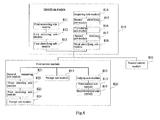
- Fig. 8 is a block diagram showing a control apparatus for a balanced vehicle according to another exemplary embodiment.
- the control apparatus for a balanced vehicle can be implemented as an entirety or a part of the balanced vehicle by means of software, hardware or a combination thereof, the control apparatus of the balanced vehicle comprises but is not limited toan identifying module 810 and a first control module 820.
- the identifying module 810 is configured to identify the type of an obstacle in front of the balanced vehicle, which type comprises: impassable obstacle; the first control module 820 is configured to, control the balanced vehicle to decelerate, when the type of the obstacle is impassable obstacle.
- the type is impassable obstacle or passable obstacle; the apparatus further comprises: a second control module 830.
- the second control module 830 is configured to increase a driving force to the balanced vehicle so that it continues moving, when the type of the obstacle is passable obstacle,.
- the identifying module 810 comprises: a first measuring sub-module 811, a first detecting sub-module 812 and a first identifying sub-module 813.
- the first measuring sub-module 811 is configured to measure the height of the obstacle in front of the balanced vehicle by means of a distance measuring component; the first detecting sub-module is configured to detect whether the height of the obstacle is greater than a predetermined threshold; the first identifying sub-module is configured to identify the obstacle as impassable type, when the height of the obstacle is greater than the predetermined threshold.
- the identifying module 810 further comprises: an acquiring sub-module 814, a second identifying sub-module 815, a calculating sub-module 816, a second detecting sub-module 817 and a third identifying sub-module 818.
- the acquiring sub-module 814 is configured to acquire an image frame in front of the balanced vehicle by means of an image acquiring component; the second identifying sub-module 815 is configured to identify the obstacle in the image frame; the calculating sub-module 816 is configured to calculate the height of the obstacle identified; the second detecting sub-module 817 is configured to detect whether the height of the obstacle is greater than a predetermined threshold; the third identifying sub-module 818 is configured to, identify the obstacle as impassable type, when the height of the obstacle is greater than the predetermined threshold.
- the above first control module 820 further comprises: a second measuring sub-module 821, a third detecting sub-module 822, and a first executing sub-module 823.
- the second measuring sub-module 821 is configured to measure a distance between the obstacle and the balanced vehicle;
- the third detecting sub-module 822 is configured to detect whether the distance is less than a predetermined distance;
- the first executing sub-module 823 is configured to execute the step of controlling the balanced vehicle to decelerate, when the distance is less than the predetermined distance,.
- the above first control module 820 further comprises: a alert sub-module 824.
- the alert sub-module 824 is configured to provide an obstacle alert in a predetermined mode, when the type of the obstacle is impassable obstacle; wherein, the predetermined mode comprises: at least one of playing a alert tone, vibrating a predetermine part of the balanced vehicle, and flickering a signal light.
- control apparatus for a balanced vehicle further comprises: a judging sub-module 825, a third control sub-module 826 and a second executing sub-module 827.
- the judging sub-module is configured to judge whether there is an alternate route in front of the balanced vehicle, when the type of the obstacle is impassable obstacle; the third control sub-module is configured to control the balanced vehicle to go along the alternate route, when the there is an alternate route in front of the balanced vehicle; the first control module is further configured to execute the step of controlling the balanced vehicle to decelerate, when there is not an alternate route in front of the balanced vehicle,.
- control apparatus for a balanced vehicle identifies the type of the obstacle in front of the balanced vehicle, and controls the balanced vehicle to decelerate if the type of the obstacle is impassable obstacle, thereby solves the problem that the driver is likely to fall over once there is an impassable obstacle in front of the balanced vehicle, and achieves the effect that the balanced vehicle can automatically identify the obstacle and try to prevent tumbles caused by rapid collision with the obstacle when the obstacle is an impassable obstacle.
- the control apparatus for a balanced vehicle provided in this embodiment measures the height and distance of the obstacle by means of the distance measuring component, thereby enables the balanced vehicle to identify the type of the obstacle and decelerate to avoid the obstacle according to the distance between the obstacle and the balanced vehicle.
- the control apparatus for a balanced vehicle provided in this embodiment also judges whether there is an alternate route in front of the balanced vehicle, and automatically controls the balanced vehicle to go along the alternate route if there is an alternate route, thereby achieves the effect of preventing collision between the balanced vehicle and the obstacles without affecting the normal traveling of the balanced vehicle.
- An exemplary embodiment of the present invention provides a balanced vehicle, which is able to implement the control method for a balanced vehicle provided in the present invention, and the balanced vehicle comprises: a control chip and a storage for storing instructions executable by the control chip. wherein, the control chip is configured to:
- Fig. 9 is a block diagram showing a balanced vehicle according to an exemplary embodiment.
- the balanced vehicle 900 can comprise one or more of a control chip 902, a storage 904, a power supply component 906, an image acquiring component 908, a distance measuring component 910, an input/output (I/O) interface 912, a sensor component 914 and a turning control component 916.
- the control chip 902 generally controls the overall control of the balanced vehicle 900, such as operations relevant to moving forward, moving backward, acceleration and deceleration.
- the control chip 902 can also comprise one or more modules to facilitate interaction between the control chip 902 and other components.
- the control chip 902 may comprise an image acquiring module to facilitate interaction between the image acquiring component 908 and the control chip 902.
- the storage 904 is configured to store various types of data so as to support operation of the balanced vehicle 900. Examples of these data comprise any instructions, image data and distance data of the balanced vehicle to be operated on the balanced vehicle 900.
- the storage 904 can be realized by any type of volatile or nonvolatile storage devices or their combinations, such as Static Random Access Memory (SRAM), Electrically Erasable Programmable Read Only Memory (EEPROM), Erasable Programmable Read Only Memory (EPROM), Programmable Read Only memory (PROM), Read Only Memory (ROM), magnetic memory, flash memory and magnetic disk or optical disc.
- SRAM Static Random Access Memory
- EEPROM Electrically Erasable Programmable Read Only Memory
- EPROM Erasable Programmable Read Only Memory
- PROM Programmable Read Only memory
- ROM Read Only Memory
- magnetic memory flash memory and magnetic disk or optical disc.
- the power supply component 906 supplies electric power to the various components of the balanced vehicle 900.
- the power component 906 may include a power supply management system, one or more power supplies and other components related to generation, management and electric power distribution of the balanced vehicle 900.
- the image acquiring component 908 is included in the balanced vehicle 900.
- the image acquiring component 908 comprises a front camera and/or a rear camera.
- the front camera and/or rear camera can receive external multimedia data.
- Each of the front camera and the rear camera can be a fixed optical lens system or can have focal lengths and optical zoom functionality.
- the distance measuring component 910 is configured to transmit and/or receive detection signal.
- the distance measuring component 910 includes a laser transmitter, when the balanced vehicle 900 is in an operation mode, such as when it receives a reflected laser, the laser transmitter is configured to receive the reflected signal of the detection signal.
- the received reflected signal can be further stored in the storage 904.
- the I/O interface 912 provides interface between the control chip 902 and the peripheral interface modules, and the above mentioned peripheral interface modules may be USB flash disk and audio player and so on.
- the sensor component 914 includes one or more sensor for providing condition assessment from every aspect for the balanced vehicle 900.
- the sensor component 914 can detect an open/close state of the balanced vehicle 900, and can detect an orientation or acceleration/deceleration changes of the balanced vehicle 900.
- the sensor component 914 may also include an optical sensor, such as CMOS or CCD image sensor, to be used in imaging apparatus.
- the sensor component 914 may include an acceleration sensor, a gyroscope sensor, a magnetic sensor, a pressure sensor or a temperature sensor, etc.
- the turning control component 916 is configured to facilitate control of turning of the balanced vehicle 900.
- the turning control component 916 may be a manual controlled turning control component, and may also be a leg controlled turning control component.
- the balanced vehicle 900 can be realized by one or more of Application Specific Integrated Circuit (ASIC), Digital Signal Processor (DSP), Digital Signal Processing Device (DSPD), Programmable Logic Device (PLD), Field Programmable Gate Array (FPGA), controller, microcontroller, microprocessor or other electronic elements, for performing the above mentioned control method for a balanced vehicle.
- ASIC Application Specific Integrated Circuit
- DSP Digital Signal Processor
- DSPD Digital Signal Processing Device
- PLD Programmable Logic Device
- FPGA Field Programmable Gate Array
- controller microcontroller, microprocessor or other electronic elements, for performing the above mentioned control method for a balanced vehicle.
Landscapes
- Engineering & Computer Science (AREA)
- Physics & Mathematics (AREA)
- Mechanical Engineering (AREA)
- Radar, Positioning & Navigation (AREA)
- Remote Sensing (AREA)
- General Physics & Mathematics (AREA)
- Automation & Control Theory (AREA)
- Aviation & Aerospace Engineering (AREA)
- Transportation (AREA)
- Chemical & Material Sciences (AREA)
- Combustion & Propulsion (AREA)
- Electromagnetism (AREA)
- Computer Vision & Pattern Recognition (AREA)
- Multimedia (AREA)
- Traffic Control Systems (AREA)
- Control Of Driving Devices And Active Controlling Of Vehicle (AREA)
- Control Of Position, Course, Altitude, Or Attitude Of Moving Bodies (AREA)
- Motorcycle And Bicycle Frame (AREA)
- Image Analysis (AREA)
- Forklifts And Lifting Vehicles (AREA)
- Train Traffic Observation, Control, And Security (AREA)
Applications Claiming Priority (1)
| Application Number | Priority Date | Filing Date | Title |
|---|---|---|---|
| CN201510627152.9A CN105223952B (zh) | 2015-09-28 | 2015-09-28 | 平衡车的控制方法及装置 |
Publications (2)
| Publication Number | Publication Date |
|---|---|
| EP3147742A2 true EP3147742A2 (de) | 2017-03-29 |
| EP3147742A3 EP3147742A3 (de) | 2017-06-28 |
Family
ID=54992982
Family Applications (1)
| Application Number | Title | Priority Date | Filing Date |
|---|---|---|---|
| EP16189763.2A Withdrawn EP3147742A3 (de) | 2015-09-28 | 2016-09-20 | Steuerungsverfahren und steuerungsvorrichtung für ein ausgeglichenes fahrzeug, computerprogramm und aufzeichnungsmedium |
Country Status (8)
| Country | Link |
|---|---|
| US (1) | US20170088134A1 (de) |
| EP (1) | EP3147742A3 (de) |
| JP (1) | JP6371840B2 (de) |
| KR (1) | KR101878083B1 (de) |
| CN (1) | CN105223952B (de) |
| MX (1) | MX359829B (de) |
| RU (1) | RU2651945C2 (de) |
| WO (1) | WO2017054346A1 (de) |
Cited By (2)
| Publication number | Priority date | Publication date | Assignee | Title |
|---|---|---|---|---|
| EP3287747A1 (de) * | 2016-08-23 | 2018-02-28 | Beijing Xiaomi Mobile Software Co., Ltd. | Verfahren und vorrichtung zur steuerung eines gleichgewichtswagens |
| EP3415405A3 (de) * | 2017-06-15 | 2019-01-02 | Hongfujin Precision Electronics (Tianjin) Co., Ltd. | Mobiles warndreieck und zugehöriges hindernisvermeidungsverfahren |
Families Citing this family (29)
| Publication number | Priority date | Publication date | Assignee | Title |
|---|---|---|---|---|
| CN106627896B (zh) * | 2017-01-04 | 2022-09-06 | 浙江骑客机器人科技有限公司 | 人机互动体感车 |
| CN105810007B (zh) * | 2016-03-29 | 2020-07-03 | 北京小米移动软件有限公司 | 平衡车停靠方法及装置 |
| CN105721834B (zh) | 2016-03-29 | 2018-12-25 | 北京小米移动软件有限公司 | 控制平衡车停靠的方法及装置 |
| WO2017206170A1 (zh) * | 2016-06-03 | 2017-12-07 | 尚艳燕 | 一种电动平衡车的控制方法和控制装置 |
| DE112017003108B4 (de) * | 2016-06-24 | 2025-05-15 | Jaguar Land Rover Limited | Verbesserungen bei der fahrzeugsteuerung |
| CN106200637A (zh) * | 2016-07-06 | 2016-12-07 | 尚艳燕 | 一种利用平衡车载物的方法和平衡车 |
| CN106020198B (zh) * | 2016-07-06 | 2020-03-31 | 深圳市汲众科技开发有限公司 | 一种体感车载物的方法和体感车 |
| WO2018006302A1 (zh) * | 2016-07-06 | 2018-01-11 | 尚艳燕 | 一种平衡车障碍物规避方法和装置 |
| CN107622666B (zh) * | 2016-07-13 | 2020-11-24 | 尚艳燕 | 一种平衡车巡航执法方法和装置 |
| CN106444747B (zh) * | 2016-09-05 | 2020-02-28 | 深圳市汲众科技开发有限公司 | 一种平衡车载物的方法和平衡车 |
| US10279786B2 (en) * | 2016-12-06 | 2019-05-07 | Aptiv Technologies Limited | Automatic braking system |
| CN106712789A (zh) * | 2016-12-12 | 2017-05-24 | 北京小米移动软件有限公司 | 控制代步车的方法及装置 |
| CN106864458B (zh) * | 2017-03-24 | 2019-12-03 | 奇瑞汽车股份有限公司 | 一种自动绕障系统及方法、智能汽车 |
| CN106774353A (zh) * | 2017-03-31 | 2017-05-31 | 成都信息工程大学 | 一种可避障自平衡车控制装置及自平衡车 |
| CN107128418A (zh) * | 2017-05-17 | 2017-09-05 | 许昌学院 | 一种通过性强的自平衡车 |
| DE102017212513A1 (de) * | 2017-07-19 | 2019-01-24 | Robert Bosch Gmbh | Verfahren und System zum Detektieren eines freien Bereiches innerhalb eines Parkplatzes |
| JP7030181B2 (ja) * | 2018-02-27 | 2022-03-04 | 本田技研工業株式会社 | 搭乗型移動体 |
| US10705194B2 (en) * | 2018-03-21 | 2020-07-07 | Zoox, Inc. | Automated detection of sensor miscalibration |
| JP7076348B2 (ja) * | 2018-09-20 | 2022-05-27 | 日立Astemo株式会社 | 電子制御装置 |
| CN109508019A (zh) * | 2018-12-28 | 2019-03-22 | 北京猎户星空科技有限公司 | 一种机器人运动控制方法、装置和存储介质 |
| CN109814576B (zh) * | 2019-02-22 | 2022-01-28 | 百度在线网络技术(北京)有限公司 | 自动驾驶车辆的速度规划方法、装置和存储介质 |
| GB2586302B (en) * | 2019-04-29 | 2021-09-22 | Motional Ad Llc | Systems and methods for implementing an autonomous vehicle response to sensor failure |
| CN110304056B (zh) * | 2019-07-29 | 2021-06-04 | 广州小鹏汽车科技有限公司 | 车辆及其控制方法与装置 |
| US11609315B2 (en) * | 2019-08-16 | 2023-03-21 | GM Cruise Holdings LLC. | Lidar sensor validation |
| CN110989623A (zh) * | 2019-12-25 | 2020-04-10 | 广州极飞科技有限公司 | 地面无人作业设备及控制其移动的方法和装置、存储介质 |
| CN113325832B (zh) * | 2020-02-28 | 2023-08-11 | 杭州萤石软件有限公司 | 一种可移动机器人避障方法以及可移动机器人 |
| USD915007S1 (en) * | 2020-06-12 | 2021-03-30 | Qiu Chen | Pet toy |
| CN114999224B (zh) * | 2022-04-29 | 2023-11-14 | 湖南喜宝达信息科技有限公司 | 一种电单车及其环境智能感测避障方法、存储介质 |
| IT202400002539A1 (it) * | 2024-02-07 | 2025-08-07 | Ferrari Spa | Sistema di controllo per autoveicolo e metodo di controllo per autoveicolo |
Family Cites Families (23)
| Publication number | Priority date | Publication date | Assignee | Title |
|---|---|---|---|---|
| US5170351A (en) * | 1990-09-18 | 1992-12-08 | Matushita Electric Industrial Co., Ltd. | Automatic guided vehicle and method for controlling travel thereof |
| JPH0627376U (ja) * | 1992-09-14 | 1994-04-12 | ヤンマー農機株式会社 | 農用トラクタの安全運転装置 |
| JP4956962B2 (ja) * | 2005-10-31 | 2012-06-20 | トヨタ自動車株式会社 | 走行装置及びその制御方法 |
| JP2007168602A (ja) * | 2005-12-21 | 2007-07-05 | Matsushita Electric Works Ltd | 二輪移動台車 |
| JP2007219986A (ja) * | 2006-02-20 | 2007-08-30 | Toyota Motor Corp | 倒立移動装置及びその制御方法 |
| JP4974934B2 (ja) * | 2008-03-05 | 2012-07-11 | Tcm株式会社 | 無人搬送車の制御方法 |
| JP5088211B2 (ja) * | 2008-04-07 | 2012-12-05 | 株式会社エクォス・リサーチ | 車両 |
| JP5304143B2 (ja) * | 2008-09-26 | 2013-10-02 | 日産自動車株式会社 | 自律走行制御装置、自律走行制御方法、及び自走車両 |
| WO2011022026A1 (en) * | 2009-08-18 | 2011-02-24 | Crown Equipment Corporation | Steer correction for a remotely operated materials handling vehicle |
| JP5372629B2 (ja) * | 2009-07-09 | 2013-12-18 | 日本電産株式会社 | ブラシレスモータ |
| CN101763119B (zh) * | 2009-12-16 | 2012-01-04 | 东南大学 | 基于遥操作移动机器人的辅助避障方法 |
| JP2011131620A (ja) * | 2009-12-22 | 2011-07-07 | Toyota Motor Corp | 倒立二輪車、その制御方法及び制御プログラム |
| JP2012126224A (ja) * | 2010-12-15 | 2012-07-05 | Bosch Corp | 倒立振子型移動体 |
| EP2489763A1 (de) * | 2011-02-15 | 2012-08-22 | Atotech Deutschland GmbH | Zink-Eisen-Legierungsschichtmaterial |
| DE102011086210A1 (de) * | 2011-11-11 | 2013-05-16 | Robert Bosch Gmbh | Verfahren zur Unterstützung eines Fahrers eines Kraftfahrzeugs sowie Vorrichtung zur Durchführung des Verfahrens |
| US20140036188A1 (en) * | 2012-08-01 | 2014-02-06 | Cheng-Hung Chen | Liquid Crystal Display Device, Array Substrate and Manufacturing Method Thereof |
| JP5996421B2 (ja) * | 2012-12-26 | 2016-09-21 | ヤマハ発動機株式会社 | 障害物検出装置及びそれを用いた車両 |
| RU2550887C2 (ru) * | 2013-06-13 | 2015-05-20 | Открытое акционерное общество "Научно-производственный комплекс "ЭЛАРА" имени Г.А. Ильенко" (ОАО "ЭЛАРА") | Бортовая интегрированная система информационной поддержки экипажа и когнитивный формат представления полетной информации на этапе "взлет" многодвигательного воздушного судна |
| CN103529450A (zh) * | 2013-10-21 | 2014-01-22 | 深圳市米克力美科技有限公司 | 无人搬运小车障碍物检测方法及其装置 |
| JP6247904B2 (ja) * | 2013-11-08 | 2017-12-13 | 日立建機株式会社 | 鉱山用運搬車両 |
| CN104765367B (zh) * | 2014-11-27 | 2015-12-02 | 无锡美联动线智能科技有限公司 | 实现智能化越障的服务机器人 |
| CN104443140A (zh) * | 2014-12-10 | 2015-03-25 | 柳州铁道职业技术学院 | 平衡车障碍检测装置 |
| CN105270525B (zh) * | 2015-09-28 | 2018-02-02 | 小米科技有限责任公司 | 两轮平衡车的控制方法及装置 |
-
2015
- 2015-09-28 CN CN201510627152.9A patent/CN105223952B/zh active Active
- 2015-12-25 JP JP2016524594A patent/JP6371840B2/ja active Active
- 2015-12-25 RU RU2016119329A patent/RU2651945C2/ru active
- 2015-12-25 MX MX2016004499A patent/MX359829B/es active IP Right Grant
- 2015-12-25 KR KR1020167009251A patent/KR101878083B1/ko active Active
- 2015-12-25 WO PCT/CN2015/099063 patent/WO2017054346A1/zh not_active Ceased
-
2016
- 2016-09-20 EP EP16189763.2A patent/EP3147742A3/de not_active Withdrawn
- 2016-09-27 US US15/277,712 patent/US20170088134A1/en not_active Abandoned
Non-Patent Citations (1)
| Title |
|---|
| None |
Cited By (3)
| Publication number | Priority date | Publication date | Assignee | Title |
|---|---|---|---|---|
| EP3287747A1 (de) * | 2016-08-23 | 2018-02-28 | Beijing Xiaomi Mobile Software Co., Ltd. | Verfahren und vorrichtung zur steuerung eines gleichgewichtswagens |
| US10671078B2 (en) | 2016-08-23 | 2020-06-02 | Beijing Xiomi Mobile Software Co., Ltd. | Method, apparatus and medium for controlling self balancing scooter |
| EP3415405A3 (de) * | 2017-06-15 | 2019-01-02 | Hongfujin Precision Electronics (Tianjin) Co., Ltd. | Mobiles warndreieck und zugehöriges hindernisvermeidungsverfahren |
Also Published As
| Publication number | Publication date |
|---|---|
| RU2651945C2 (ru) | 2018-04-24 |
| EP3147742A3 (de) | 2017-06-28 |
| JP2017538610A (ja) | 2017-12-28 |
| US20170088134A1 (en) | 2017-03-30 |
| CN105223952A (zh) | 2016-01-06 |
| KR20180050187A (ko) | 2018-05-14 |
| JP6371840B2 (ja) | 2018-08-08 |
| MX359829B (es) | 2018-10-10 |
| WO2017054346A1 (zh) | 2017-04-06 |
| MX2016004499A (es) | 2017-06-09 |
| KR101878083B1 (ko) | 2018-07-13 |
| CN105223952B (zh) | 2019-03-29 |
| RU2016119329A (ru) | 2017-12-07 |
Similar Documents
| Publication | Publication Date | Title |
|---|---|---|
| EP3147742A2 (de) | Steuerungsverfahren und steuerungsvorrichtung für ein ausgeglichenes fahrzeug, computerprogramm und aufzeichnungsmedium | |
| EP3147740B1 (de) | Steuerungsverfahren und vorrichtung für einen zweirädrigen spannwagen, computerprogramm und aufzeichnungsmedium | |
| US11615629B2 (en) | Estimation of time to collision in a computer vision system | |
| US10929986B2 (en) | Techniques for using a simple neural network model and standard camera for image detection in autonomous driving | |
| CN113554698A (zh) | 车辆位姿信息生成方法、装置及电子设备、存储介质 | |
| JP2015518600A5 (de) | ||
| JP6819205B2 (ja) | 駐車スペース検出装置、電子機器及び方法 | |
| US20170220874A1 (en) | Partially occluded object detection using context and depth ordering | |
| US20170344888A1 (en) | Information processing apparatus and information processing method | |
| JP6429452B2 (ja) | 車載用画像処理装置及び半導体装置 | |
| CN114537521B (zh) | 停车辅助设备和方法 | |
| US20200089976A1 (en) | Method and device of multi-focal sensing of an obstacle and non-volatile computer-readable storage medium | |
| CN111157014A (zh) | 路况展示方法、装置及车载终端、存储介质 | |
| US20180061075A1 (en) | Distance measurement device and image capturing control device | |
| JPWO2019021354A1 (ja) | 車両駐車支援装置、車両駐車支援プログラム | |
| CN114286772B (zh) | 自动驾驶控制装置以及自动驾驶控制方法 | |
| US9245342B2 (en) | Obstacle detection device | |
| CN114268788B (zh) | 车载车辆图像采集装置功能符合性的监测 | |
| US11037003B2 (en) | Electronic device and method for detecting obstacle | |
| US20210321062A1 (en) | Image processing device in moving object, imaging device, image processing method, and recording medium | |
| JP7643472B2 (ja) | 物体検出装置、物体検出方法、および物体検出用コンピュータプログラム | |
| JP7762551B2 (ja) | 物体検知装置、物体検知方法および物体検知プログラム | |
| TW201323262A (zh) | 車輛輔助系統及車輛輔助方法 | |
| EP4194883A1 (de) | Vorrichtung und verfahren zur bestimmung von objekten um ein fahrzeug herum | |
| CN121121695A (zh) | 自动泊车过程障碍物检测方法、系统、电子设备及可读介质 |
Legal Events
| Date | Code | Title | Description |
|---|---|---|---|
| PUAI | Public reference made under article 153(3) epc to a published international application that has entered the european phase |
Free format text: ORIGINAL CODE: 0009012 |
|
| AK | Designated contracting states |
Kind code of ref document: A2 Designated state(s): AL AT BE BG CH CY CZ DE DK EE ES FI FR GB GR HR HU IE IS IT LI LT LU LV MC MK MT NL NO PL PT RO RS SE SI SK SM TR |
|
| AX | Request for extension of the european patent |
Extension state: BA ME |
|
| PUAL | Search report despatched |
Free format text: ORIGINAL CODE: 0009013 |
|
| AK | Designated contracting states |
Kind code of ref document: A3 Designated state(s): AL AT BE BG CH CY CZ DE DK EE ES FI FR GB GR HR HU IE IS IT LI LT LU LV MC MK MT NL NO PL PT RO RS SE SI SK SM TR |
|
| AX | Request for extension of the european patent |
Extension state: BA ME |
|
| RIC1 | Information provided on ipc code assigned before grant |
Ipc: G05D 1/02 20060101ALI20170522BHEP Ipc: G05D 1/08 20060101AFI20170522BHEP Ipc: B62K 11/00 20060101ALI20170522BHEP |
|
| STAA | Information on the status of an ep patent application or granted ep patent |
Free format text: STATUS: THE APPLICATION IS DEEMED TO BE WITHDRAWN |
|
| 18D | Application deemed to be withdrawn |
Effective date: 20180103 |