EP3147744A1 - Vorrichtung zur regelung von durchfluss und temperatur in einer dusche oder badewanne oder in einem badspülbecken oder küchenspülbecken - Google Patents
Vorrichtung zur regelung von durchfluss und temperatur in einer dusche oder badewanne oder in einem badspülbecken oder küchenspülbecken Download PDFInfo
- Publication number
- EP3147744A1 EP3147744A1 EP15186816.3A EP15186816A EP3147744A1 EP 3147744 A1 EP3147744 A1 EP 3147744A1 EP 15186816 A EP15186816 A EP 15186816A EP 3147744 A1 EP3147744 A1 EP 3147744A1
- Authority
- EP
- European Patent Office
- Prior art keywords
- cylinders
- collars
- flow rate
- cold water
- mixing chamber
- Prior art date
- Legal status (The legal status is an assumption and is not a legal conclusion. Google has not performed a legal analysis and makes no representation as to the accuracy of the status listed.)
- Withdrawn
Links
- 230000001105 regulatory effect Effects 0.000 title claims abstract description 15
- XLYOFNOQVPJJNP-UHFFFAOYSA-N water Substances O XLYOFNOQVPJJNP-UHFFFAOYSA-N 0.000 claims abstract description 58
- 239000012530 fluid Substances 0.000 claims abstract description 18
- 238000011144 upstream manufacturing Methods 0.000 claims description 2
- 238000009434 installation Methods 0.000 description 4
- 230000003111 delayed effect Effects 0.000 description 1
- 238000010438 heat treatment Methods 0.000 description 1
- 230000007257 malfunction Effects 0.000 description 1
- 230000002035 prolonged effect Effects 0.000 description 1
Images




Classifications
-
- F—MECHANICAL ENGINEERING; LIGHTING; HEATING; WEAPONS; BLASTING
- F16—ENGINEERING ELEMENTS AND UNITS; GENERAL MEASURES FOR PRODUCING AND MAINTAINING EFFECTIVE FUNCTIONING OF MACHINES OR INSTALLATIONS; THERMAL INSULATION IN GENERAL
- F16K—VALVES; TAPS; COCKS; ACTUATING-FLOATS; DEVICES FOR VENTING OR AERATING
- F16K11/00—Multiple-way valves, e.g. mixing valves; Pipe fittings incorporating such valves
- F16K11/10—Multiple-way valves, e.g. mixing valves; Pipe fittings incorporating such valves with two or more closure members not moving as a unit
- F16K11/20—Multiple-way valves, e.g. mixing valves; Pipe fittings incorporating such valves with two or more closure members not moving as a unit operated by separate actuating members
- F16K11/22—Multiple-way valves, e.g. mixing valves; Pipe fittings incorporating such valves with two or more closure members not moving as a unit operated by separate actuating members with an actuating member for each valve, e.g. interconnected to form multiple-way valves
-
- F—MECHANICAL ENGINEERING; LIGHTING; HEATING; WEAPONS; BLASTING
- F16—ENGINEERING ELEMENTS AND UNITS; GENERAL MEASURES FOR PRODUCING AND MAINTAINING EFFECTIVE FUNCTIONING OF MACHINES OR INSTALLATIONS; THERMAL INSULATION IN GENERAL
- F16K—VALVES; TAPS; COCKS; ACTUATING-FLOATS; DEVICES FOR VENTING OR AERATING
- F16K19/00—Arrangements of valves and flow lines specially adapted for mixing fluids
- F16K19/006—Specially adapted for faucets
-
- F—MECHANICAL ENGINEERING; LIGHTING; HEATING; WEAPONS; BLASTING
- F16—ENGINEERING ELEMENTS AND UNITS; GENERAL MEASURES FOR PRODUCING AND MAINTAINING EFFECTIVE FUNCTIONING OF MACHINES OR INSTALLATIONS; THERMAL INSULATION IN GENERAL
- F16K—VALVES; TAPS; COCKS; ACTUATING-FLOATS; DEVICES FOR VENTING OR AERATING
- F16K31/00—Actuating devices; Operating means; Releasing devices
- F16K31/02—Actuating devices; Operating means; Releasing devices electric; magnetic
- F16K31/04—Actuating devices; Operating means; Releasing devices electric; magnetic using a motor
- F16K31/041—Actuating devices; Operating means; Releasing devices electric; magnetic using a motor for rotating valves
-
- G—PHYSICS
- G05—CONTROLLING; REGULATING
- G05D—SYSTEMS FOR CONTROLLING OR REGULATING NON-ELECTRIC VARIABLES
- G05D23/00—Control of temperature
- G05D23/01—Control of temperature without auxiliary power
- G05D23/13—Control of temperature without auxiliary power by varying the mixing ratio of two fluids having different temperatures
- G05D23/1393—Control of temperature without auxiliary power by varying the mixing ratio of two fluids having different temperatures characterised by the use of electric means
Definitions
- the present invention relates to a device for regulating the flow rate and temperature in a shower or bathtub or in a sink of a bathroom or kitchen.
- the present invention relates to a device of the aforementioned type, in which regulation of the flow rate and the temperature is performed electrically.
- Such devices comprise closing members electrically controlled from a pushbutton unit which can be mounted for example on the shower panel or on the bathtub, on the kitchen worktop or on the bathroom sink and which is electrically connected to electrical actuators of said closing members.
- the actuators, closing members and substantially all the other components of the device are installed concealed behind the shower panel or between the bathtub and the wall, underneath the worktop or underneath the sink, leaving only the pushbutton unit visible.
- the various components to be installed in a concealed manner occupy a space which complicates the work of the installation engineer or results in the need to provide a relatively large receiving seat in the shower panel, behind the bathtub or underneath the sink, with the inevitable consequence of reducing the space available for the user, for example underneath the sink, or altering the aesthetic appearance of the installation.
- the known devices are not suitable for operation in certain particular conditions, for example when the pressure of the hot or cold water from the supply network, from a boiler or from a heating unit is high. In such cases it happens that the actuators are unable to move the closing members or the movement of the closing members is delayed by the high pressure of the water, producing an error or a delay in regulation. It also happens that the actuators may be subject to faults or malfunctions owing to prolonged use under high-pressure conditions.
- the technical problem forming the basis of the present invention is that of devising an electric device for regulating the flow rate and the temperature of the water which is able to perform very precise regulation, while operating under high-pressure conditions, assembling all the regulation components together in a small amount of space, thus substantially overcoming the drawbacks which hitherto affect the devices of the prior art.
- the idea underlying the present invention is to control the temperature and the flow rate of the water by means of two closing members sliding along a same axis X perpendicular to the hot water and cold water inlets and actuating the closing members by means of two electric motors.
- the closing members are cylindrical and hollow and have an opening sliding on a guide collar and an opposite opening designed to close the flow, when engaged over a collar situated opposite the guide collar, and open the flow, when disengaged from said opposite collar.
- the collars project from a base and the cylinders, also on the end-of-travel positions, corresponding to full opening or closing of the flow, are arranged at a distance from the base.
- This distance allows the water to exert a substantially equivalent pressure on the opposite base profiles of the cylinders, practically eliminating the resistance of the water along the axis X on which the closing members slide.
- the pressure exerted on the side surface of the cylinder is also perfectly balanced. Such a configuration allows low-power and small-size electric motors to be used even when the water has a high pressure.
- the collars are situated opposite the guide collars on which the cylinders are slidingly engaged.
- the device also comprises:
- the main body also forms guide collars on which the two cylinders are slidable between a position for fully opening the flow, corresponding to predetermined and maximum superimposition of the cylinder on the guide collar, and a position for closing the flow, corresponding to predetermined and minimum superimposition of the cylinder on the guide collar and superimposition of the cylinder on the collar opposite the guide collar.
- the cylinders are independently adjustable.
- a travel movement of one cylinder on the respective guide collar is adjustable independently from a travel movement of the other cylinder on the respective guide collar, and said travel movements correspond to a flow rate of hot water or cold water.
- the main body also forms a base of the guide collars.
- the cylinders never make contact with the base of the guide collars, not even in the end-of-travel positions, allowing the water between the base of the guide collar and the base profile of the cylinders to counterbalance the pressure exerted by the water on the opposite base profile of the cylinders.
- the inlets are parallel to each other and perpendicular to the axis of the two cylinders.
- the collars situated opposite the guide collars extend from a base of the side blocks.
- the cylinders do not come into contact even with the base of the oppositely arranged collars.
- the mixing chamber comprises a mixing path or a labyrinth designed to mix the water from the hot water and cold water inlets upstream of the outlet.
- the mixing chamber comprises a block mounted on the main body by means of a threaded equidistant from the axes Y', Y" of the inlets.
- the block delimits the outlet.
- the outlet is perpendicular to the axis X of the cylinders and is not coaxial with the axes of the inlets Y', Y" and the axis Y of the threaded.
- a temperature sensor is mounted at the outlet and is disconnected from an electronic board for regulating the electric motors which receive at their input a temperature measured by the sensor and implements a feedback loop such as to correct the position of the cylinders if the temperature measured is different from a temperature set by the user. Also provided are small pillars which are fixed to the base of the side bodies around the collars, at an angular distance of 120°, and form an anti-vibration guide for one end of the cylinders.
- the said cylinders are fixed to the guide shafts by means of respective discs which have a central hub and three equidistant radial arms terminating on the cylinders.
- the device is portable. For example it has dimensions of 10 cm x 10 cm x 5 cm. It can also be installed concealed behind a shower panel or underneath a sink.
- the device comprises a transformer for powering the electric board and the motors, which is connected to an electric terminal or plug.
- Said terminal is designed to be connected to an a.c. electric household socket.
- the device also comprises a keypad or touch screen interface for sending commands for regulating the flow rate or the temperature to the electronic board.
- Figures 1-6 show a device for regulating the flow rate and the temperature for a shower, a bathtub or a sink of a bathroom or kitchen according to the present invention, and in particular a device designed to perform the regulation electrically.
- the device is portable and can be mounted on the shower panel or on the bathtub, on the worktop of the kitchen or on the basin of the bathroom and can be connected electrically to an electric power supply socket, for example a wall socket.
- the device is powered by a battery, which is preferably rechargeable.
- Figure 1 is a side view of the device 1.
- the device comprises a main body 14 on which two coaxial side bodies 12, 13 are mounted on opposite sides, said bodies also forming a connecting mount for two respective electric motors 8, 9.
- An outlet 5 for the mixed fluid is perpendicular to the axis of the side bodies 12, 13 or to a plane passing through said axis, and a sensor 100 is mounted on the outlet 5 for measuring the temperature of the outlet water.
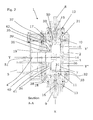
- FIG 2 is a cross-section along the plane A-A of the device shown in Figure 1 , in which two closing cylinders 6, 7 are visible.
- Each cylinder 6, 7 is coupled to a guide shaft 15, 16 of a respective electric motor 8, 9 by means of a disc 30.
- the disc 30 comprises a central hub 32 and three radial arms 32 which extend from the central hub 32 and terminate in a thickness of the cylinders 6, 7.
- the hub 32 is fixed to the guide shaft 15, 16, for example to one end of the shaft 15, 16.
- the three radial arms are angularly spaced. However, it is also possible to use only two radial arms or more than three radial arms which are equidistant.
- Grooves are provided along the inner side surface of each cylinder 6, 7 and the discs 30 are engaged inside them at a predetermined distance from the base of the cylinder.
- Each electric motor is connected to an electronic board (not shown) of the device, which is enclosed inside a hydraulically sealed seat and which controls the motors, causing the advancing movement or retraction of the guide shaft 15, 16 and the associated cylinder 6, 7 along the axis X.
- the command is issued via a pushbutton unit connected electrically to the circuit board, preferably a pushbutton unit with two pushbuttons for increasing or reducing the flow rate, two pushbuttons for increasing or lowering the temperature and a pushbutton for opening or closing the flow.
- the side bodies 12, 13 have respective bases 17, 18 which are directed towards the inside of the device 1 and from which two collars 10, 11 provided with a respective seal project.
- Each cylinder 6, 7 is slidable until it engages with a base 37, 38 on the collar 10, 11, so as to engage with the seal and close the flow entering via respective hot water and cold water inlets 2, 3.
- the inlets 2, 3 have their axes Y', Y" perpendicular to the axis X of the cylinders 6, 7 and are formed in the main body 14 which also forms guide collars 33, 34 for a portion 41, 42 of the cylinders 6, 7 comprising a base 35, 36 situated opposite the base 37, 38 intended to close the flow.
- the flow rate corresponds to a distance of the base 37, 38 of the cylinder 6, 7 from the collar 10, 11, i.e. the greater the distance, the greater is the flow rate.
- the cylinder 6, 7 is engaged over both the collars 10, 11 and closes the passage between the two collars 10, 11.
- the internal cross-section of the cylinders 6, 7 is greater than or equal to maximum flow rate, i.e. to the maximum distance between the base 37, 38 of the cylinder 6, 7 and the collar 10, 11 measured at the end of the shaft 15, 16.
- the cross-section of the cylinder 6, 7 does not limit the flow rate along the fluid flow path towards the outlet and favours a total radial opening.
- the portion 41, 42 of the cylinders 6, 7 comprising the base 35, 36 is slidable on the guide collars 33, 34, leaving however a space between the base 39, 40 of the guide collars 33, 34 and the base 35, 36 of the cylinders 6, 7, also in the position where the cylinders 6, 7 are furthest advanced on the guide collars 33, 34.
- the other base 37, 38 of the cylinders does not make contact with the base 17, 18 of the collars 10, 11, not even in the position where the cylinders 6, 7 are fully retracted from the guide collars 33, 34.
- such a sliding movement of the cylinders 6, 7 allows the water to exert an equal pressure on the profiles of the base 35, 36 and on the profiles of the bases 37, 38 of the cylinders 6, 7, without creating any obstacle to the sliding movement of the cylinders 6, 7 and therefore minimizing the electric power used by the electric motor to move the cylinders 6, 7.
- the radial pressure exerted on the side surface of the cylinders 6, 7 does not influence particularly the axial sliding thereof and is balanced since it acts along the entire side surface.
- the cylinders are immersed inside a chamber 50 formed by the main body 14 and by the side bodies 12, 13.
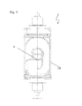
- a body 19 which forms a chamber 4 for mixing the hot water and cold water is preferably mounted on an outlet 51 of said chamber 50, as can be seen in Figure 4 .
- the mixing chamber 4 forms a forced flow path for the hot water towards the cold water and vice versa, forcing the two water flows to meet and be mixed before flowing into the outlet 5 where the temperature is measured.
- the temperature of the mixed water is detected by the sensor 100 and compared in the electronic board with a value set by the user via the pushbutton unit. In the event of a difference between the temperature detected and the set temperature, the electronic board automatically regulates the position of the cylinders.
- the installation of the components of the device 1 is particularly facilitated: firstly the cylinders 6, 7 are inserted inside the side bodies 12 and 13 including the discs 30, then the electric motors including the guide shafts 15, 16 with the respective seals are mounted; finally, the side bodies 12, 13 and the mixer 19 which incorporates the mixing chamber and the outlet 5 are mounted on the main body 14.
- the installation of the portable device is also greatly simplified. Underneath the sink or behind the shower panel the flexible pipes for supplying the hot water and cold water are connected to the inlets 2, 3 and the outlet 5 is connected to the water tap.
- the keypad is fixed onto the basin or onto the shower panel in a visible position.
- the device is connected to an electric socket. It is envisaged using rechargeable batteries and non-rechargeable batteries as a power supply unit; in this case a connection to the electric mains power is not required.
Landscapes
- Engineering & Computer Science (AREA)
- General Engineering & Computer Science (AREA)
- Mechanical Engineering (AREA)
- Physics & Mathematics (AREA)
- General Physics & Mathematics (AREA)
- Automation & Control Theory (AREA)
- Temperature-Responsive Valves (AREA)
- Domestic Plumbing Installations (AREA)
Priority Applications (1)
| Application Number | Priority Date | Filing Date | Title |
|---|---|---|---|
| EP15186816.3A EP3147744A1 (de) | 2015-09-25 | 2015-09-25 | Vorrichtung zur regelung von durchfluss und temperatur in einer dusche oder badewanne oder in einem badspülbecken oder küchenspülbecken |
Applications Claiming Priority (1)
| Application Number | Priority Date | Filing Date | Title |
|---|---|---|---|
| EP15186816.3A EP3147744A1 (de) | 2015-09-25 | 2015-09-25 | Vorrichtung zur regelung von durchfluss und temperatur in einer dusche oder badewanne oder in einem badspülbecken oder küchenspülbecken |
Publications (1)
| Publication Number | Publication Date |
|---|---|
| EP3147744A1 true EP3147744A1 (de) | 2017-03-29 |
Family
ID=54396701
Family Applications (1)
| Application Number | Title | Priority Date | Filing Date |
|---|---|---|---|
| EP15186816.3A Withdrawn EP3147744A1 (de) | 2015-09-25 | 2015-09-25 | Vorrichtung zur regelung von durchfluss und temperatur in einer dusche oder badewanne oder in einem badspülbecken oder küchenspülbecken |
Country Status (1)
| Country | Link |
|---|---|
| EP (1) | EP3147744A1 (de) |
Cited By (1)
| Publication number | Priority date | Publication date | Assignee | Title |
|---|---|---|---|---|
| WO2019031971A1 (en) * | 2017-08-08 | 2019-02-14 | Unova Limited | ELECTRONICALLY CONTROLLED VALVES AND MIXING VALVES |
Citations (3)
| Publication number | Priority date | Publication date | Assignee | Title |
|---|---|---|---|---|
| EP0320564A2 (de) * | 1987-12-17 | 1989-06-21 | Matsushita Electric Industrial Co., Ltd. | Temperaturregulierbares Wasserzufuhrsystem |
| EP0375259A2 (de) * | 1988-12-23 | 1990-06-27 | Matsushita Electric Works, Ltd. | Warmwasserversorgungssystem |
| EP2450603A1 (de) * | 2010-11-09 | 2012-05-09 | Fabrizio Nobili | Mischbatterie für Küche oder Badezimmer |
-
2015
- 2015-09-25 EP EP15186816.3A patent/EP3147744A1/de not_active Withdrawn
Patent Citations (3)
| Publication number | Priority date | Publication date | Assignee | Title |
|---|---|---|---|---|
| EP0320564A2 (de) * | 1987-12-17 | 1989-06-21 | Matsushita Electric Industrial Co., Ltd. | Temperaturregulierbares Wasserzufuhrsystem |
| EP0375259A2 (de) * | 1988-12-23 | 1990-06-27 | Matsushita Electric Works, Ltd. | Warmwasserversorgungssystem |
| EP2450603A1 (de) * | 2010-11-09 | 2012-05-09 | Fabrizio Nobili | Mischbatterie für Küche oder Badezimmer |
Cited By (5)
| Publication number | Priority date | Publication date | Assignee | Title |
|---|---|---|---|---|
| WO2019031971A1 (en) * | 2017-08-08 | 2019-02-14 | Unova Limited | ELECTRONICALLY CONTROLLED VALVES AND MIXING VALVES |
| CN111133238A (zh) * | 2017-08-08 | 2020-05-08 | 龙诺瓦有限公司 | 电子可控阀和混合阀 |
| US11650607B2 (en) | 2017-08-08 | 2023-05-16 | Unova Limited | Electronically controllable valves and mixing valves |
| CN111133238B (zh) * | 2017-08-08 | 2023-11-17 | 龙诺瓦有限公司 | 电子可控阀和混合阀 |
| AU2018312822B2 (en) * | 2017-08-08 | 2024-07-25 | Unova Limited | Electronically controllable valves and mixing valves |
Similar Documents
| Publication | Publication Date | Title |
|---|---|---|
| US10577784B2 (en) | Shower head with integrated mixing valve | |
| KR101755243B1 (ko) | 스마트한 온수제공시스템 | |
| CN108006949B (zh) | 电热水器及其恒温控制装置 | |
| EP2977657A1 (de) | Wasserhahnstruktur für konstante wassertemperatur | |
| EP3147744A1 (de) | Vorrichtung zur regelung von durchfluss und temperatur in einer dusche oder badewanne oder in einem badspülbecken oder küchenspülbecken | |
| CN201723783U (zh) | 恒温节能水龙头及相关阀芯和阀芯切换组件 | |
| CN204004580U (zh) | 恒温龙头结构 | |
| EP3812630A1 (de) | Wassertrennventil und wassertrennhahn | |
| WO2007096771A2 (en) | Sanitary valve, water-supply device using said valve and system for managing and distributing water within a building that uses said device | |
| US10288317B2 (en) | Flow controller and a hot water appliance provided therewith | |
| CN203849624U (zh) | 一种节能出水温控系统 | |
| CN104964065A (zh) | 一种冷热水控制阀 | |
| CN205350430U (zh) | 一种流量控制阀 | |
| CN104235418A (zh) | 一种温控水龙头 | |
| CN209688168U (zh) | 一种温控淋浴龙头 | |
| CN201810822U (zh) | 一种双柄水龙头 | |
| CN103953751B (zh) | 4个水管接头的混水阀 | |
| CN203146905U (zh) | 一种自动混水阀 | |
| CN211449781U (zh) | 一种具有调节水压平衡的阀芯 | |
| CN209483986U (zh) | 一种一体式多功能阀芯 | |
| WO2016190730A1 (en) | Flow controller and a hot water appliance provided therewith | |
| CN221331029U (zh) | 一种水电双控的淋浴屏 | |
| CN104595529A (zh) | 一种水温控制器 | |
| CN218094395U (zh) | 混水阀及电热水器 | |
| CN223635453U (zh) | 一种出水阀 |
Legal Events
| Date | Code | Title | Description |
|---|---|---|---|
| PUAI | Public reference made under article 153(3) epc to a published international application that has entered the european phase |
Free format text: ORIGINAL CODE: 0009012 |
|
| AK | Designated contracting states |
Kind code of ref document: A1 Designated state(s): AL AT BE BG CH CY CZ DE DK EE ES FI FR GB GR HR HU IE IS IT LI LT LU LV MC MK MT NL NO PL PT RO RS SE SI SK SM TR |
|
| AX | Request for extension of the european patent |
Extension state: BA ME |
|
| STAA | Information on the status of an ep patent application or granted ep patent |
Free format text: STATUS: THE APPLICATION IS DEEMED TO BE WITHDRAWN |
|
| 18D | Application deemed to be withdrawn |
Effective date: 20170930 |