EP3147745A2 - System und verfahren zur gasentsorgung - Google Patents
System und verfahren zur gasentsorgung Download PDFInfo
- Publication number
- EP3147745A2 EP3147745A2 EP16191067.4A EP16191067A EP3147745A2 EP 3147745 A2 EP3147745 A2 EP 3147745A2 EP 16191067 A EP16191067 A EP 16191067A EP 3147745 A2 EP3147745 A2 EP 3147745A2
- Authority
- EP
- European Patent Office
- Prior art keywords
- feedstock
- mixing vessel
- discharge
- solvent
- abnormal
- Prior art date
- Legal status (The legal status is an assumption and is not a legal conclusion. Google has not performed a legal analysis and makes no representation as to the accuracy of the status listed.)
- Granted
Links
Images

Classifications
-
- B—PERFORMING OPERATIONS; TRANSPORTING
- B01—PHYSICAL OR CHEMICAL PROCESSES OR APPARATUS IN GENERAL
- B01F—MIXING, e.g. DISSOLVING, EMULSIFYING OR DISPERSING
- B01F21/00—Dissolving
- B01F21/30—Workflow diagrams or layout of plants, e.g. flow charts; Details of workflow diagrams or layout of plants, e.g. controlling means
-
- B—PERFORMING OPERATIONS; TRANSPORTING
- B01—PHYSICAL OR CHEMICAL PROCESSES OR APPARATUS IN GENERAL
- B01F—MIXING, e.g. DISSOLVING, EMULSIFYING OR DISPERSING
- B01F21/00—Dissolving
- B01F21/02—Methods
-
- B—PERFORMING OPERATIONS; TRANSPORTING
- B01—PHYSICAL OR CHEMICAL PROCESSES OR APPARATUS IN GENERAL
- B01F—MIXING, e.g. DISSOLVING, EMULSIFYING OR DISPERSING
- B01F23/00—Mixing according to the phases to be mixed, e.g. dispersing or emulsifying
- B01F23/20—Mixing gases with liquids
- B01F23/23—Mixing gases with liquids by introducing gases into liquid media, e.g. for producing aerated liquids
- B01F23/231—Mixing gases with liquids by introducing gases into liquid media, e.g. for producing aerated liquids by bubbling
-
- B—PERFORMING OPERATIONS; TRANSPORTING
- B01—PHYSICAL OR CHEMICAL PROCESSES OR APPARATUS IN GENERAL
- B01F—MIXING, e.g. DISSOLVING, EMULSIFYING OR DISPERSING
- B01F23/00—Mixing according to the phases to be mixed, e.g. dispersing or emulsifying
- B01F23/20—Mixing gases with liquids
- B01F23/23—Mixing gases with liquids by introducing gases into liquid media, e.g. for producing aerated liquids
- B01F23/234—Surface aerating
- B01F23/2341—Surface aerating by cascading, spraying or projecting a liquid into a gaseous atmosphere
-
- B—PERFORMING OPERATIONS; TRANSPORTING
- B01—PHYSICAL OR CHEMICAL PROCESSES OR APPARATUS IN GENERAL
- B01F—MIXING, e.g. DISSOLVING, EMULSIFYING OR DISPERSING
- B01F23/00—Mixing according to the phases to be mixed, e.g. dispersing or emulsifying
- B01F23/20—Mixing gases with liquids
- B01F23/29—Mixing systems, i.e. flow charts or diagrams
-
- B—PERFORMING OPERATIONS; TRANSPORTING
- B01—PHYSICAL OR CHEMICAL PROCESSES OR APPARATUS IN GENERAL
- B01F—MIXING, e.g. DISSOLVING, EMULSIFYING OR DISPERSING
- B01F35/00—Accessories for mixers; Auxiliary operations or auxiliary devices; Parts or details of general application
- B01F35/20—Measuring; Control or regulation
- B01F35/21—Measuring
- B01F35/211—Measuring of the operational parameters
- B01F35/2112—Level of material in a container or the position or shape of the upper surface of the material
-
- B—PERFORMING OPERATIONS; TRANSPORTING
- B01—PHYSICAL OR CHEMICAL PROCESSES OR APPARATUS IN GENERAL
- B01F—MIXING, e.g. DISSOLVING, EMULSIFYING OR DISPERSING
- B01F35/00—Accessories for mixers; Auxiliary operations or auxiliary devices; Parts or details of general application
- B01F35/20—Measuring; Control or regulation
- B01F35/21—Measuring
- B01F35/211—Measuring of the operational parameters
- B01F35/2113—Pressure
-
- B—PERFORMING OPERATIONS; TRANSPORTING
- B01—PHYSICAL OR CHEMICAL PROCESSES OR APPARATUS IN GENERAL
- B01F—MIXING, e.g. DISSOLVING, EMULSIFYING OR DISPERSING
- B01F35/00—Accessories for mixers; Auxiliary operations or auxiliary devices; Parts or details of general application
- B01F35/20—Measuring; Control or regulation
- B01F35/21—Measuring
- B01F35/211—Measuring of the operational parameters
- B01F35/2115—Temperature
-
- B—PERFORMING OPERATIONS; TRANSPORTING
- B01—PHYSICAL OR CHEMICAL PROCESSES OR APPARATUS IN GENERAL
- B01F—MIXING, e.g. DISSOLVING, EMULSIFYING OR DISPERSING
- B01F35/00—Accessories for mixers; Auxiliary operations or auxiliary devices; Parts or details of general application
- B01F35/20—Measuring; Control or regulation
- B01F35/22—Control or regulation
- B01F35/221—Control or regulation of operational parameters, e.g. level of material in the mixer, temperature or pressure
- B01F35/2212—Level of the material in the mixer
-
- B—PERFORMING OPERATIONS; TRANSPORTING
- B63—SHIPS OR OTHER WATERBORNE VESSELS; RELATED EQUIPMENT
- B63G—OFFENSIVE OR DEFENSIVE ARRANGEMENTS ON VESSELS; MINE-LAYING; MINE-SWEEPING; SUBMARINES; AIRCRAFT CARRIERS
- B63G8/00—Underwater vessels, e.g. submarines; Equipment specially adapted therefor
- B63G8/08—Propulsion
-
- F—MECHANICAL ENGINEERING; LIGHTING; HEATING; WEAPONS; BLASTING
- F01—MACHINES OR ENGINES IN GENERAL; ENGINE PLANTS IN GENERAL; STEAM ENGINES
- F01N—GAS-FLOW SILENCERS OR EXHAUST APPARATUS FOR MACHINES OR ENGINES IN GENERAL; GAS-FLOW SILENCERS OR EXHAUST APPARATUS FOR INTERNAL-COMBUSTION ENGINES
- F01N13/00—Exhaust or silencing apparatus characterised by constructional features
- F01N13/12—Exhaust or silencing apparatus characterised by constructional features specially adapted for submerged exhausting
-
- F—MECHANICAL ENGINEERING; LIGHTING; HEATING; WEAPONS; BLASTING
- F01—MACHINES OR ENGINES IN GENERAL; ENGINE PLANTS IN GENERAL; STEAM ENGINES
- F01N—GAS-FLOW SILENCERS OR EXHAUST APPARATUS FOR MACHINES OR ENGINES IN GENERAL; GAS-FLOW SILENCERS OR EXHAUST APPARATUS FOR INTERNAL-COMBUSTION ENGINES
- F01N3/00—Exhaust or silencing apparatus having means for purifying, rendering innocuous, or otherwise treating exhaust
- F01N3/02—Exhaust or silencing apparatus having means for purifying, rendering innocuous, or otherwise treating exhaust for cooling, or for removing solid constituents of, exhaust
- F01N3/04—Exhaust or silencing apparatus having means for purifying, rendering innocuous, or otherwise treating exhaust for cooling, or for removing solid constituents of, exhaust using liquids
-
- F—MECHANICAL ENGINEERING; LIGHTING; HEATING; WEAPONS; BLASTING
- F01—MACHINES OR ENGINES IN GENERAL; ENGINE PLANTS IN GENERAL; STEAM ENGINES
- F01N—GAS-FLOW SILENCERS OR EXHAUST APPARATUS FOR MACHINES OR ENGINES IN GENERAL; GAS-FLOW SILENCERS OR EXHAUST APPARATUS FOR INTERNAL-COMBUSTION ENGINES
- F01N9/00—Electrical control of exhaust gas treating apparatus
-
- G—PHYSICS
- G05—CONTROLLING; REGULATING
- G05D—SYSTEMS FOR CONTROLLING OR REGULATING NON-ELECTRIC VARIABLES
- G05D21/00—Control of chemical or physico-chemical variables, e.g. pH value
- G05D21/02—Control of chemical or physico-chemical variables, e.g. pH value characterised by the use of electric means
-
- F—MECHANICAL ENGINEERING; LIGHTING; HEATING; WEAPONS; BLASTING
- F01—MACHINES OR ENGINES IN GENERAL; ENGINE PLANTS IN GENERAL; STEAM ENGINES
- F01N—GAS-FLOW SILENCERS OR EXHAUST APPARATUS FOR MACHINES OR ENGINES IN GENERAL; GAS-FLOW SILENCERS OR EXHAUST APPARATUS FOR INTERNAL-COMBUSTION ENGINES
- F01N2590/00—Exhaust or silencing apparatus adapted to particular use, e.g. for military applications, airplanes, submarines
- F01N2590/02—Exhaust or silencing apparatus adapted to particular use, e.g. for military applications, airplanes, submarines for marine vessels or naval applications
-
- Y—GENERAL TAGGING OF NEW TECHNOLOGICAL DEVELOPMENTS; GENERAL TAGGING OF CROSS-SECTIONAL TECHNOLOGIES SPANNING OVER SEVERAL SECTIONS OF THE IPC; TECHNICAL SUBJECTS COVERED BY FORMER USPC CROSS-REFERENCE ART COLLECTIONS [XRACs] AND DIGESTS
- Y02—TECHNOLOGIES OR APPLICATIONS FOR MITIGATION OR ADAPTATION AGAINST CLIMATE CHANGE
- Y02T—CLIMATE CHANGE MITIGATION TECHNOLOGIES RELATED TO TRANSPORTATION
- Y02T10/00—Road transport of goods or passengers
- Y02T10/10—Internal combustion engine [ICE] based vehicles
- Y02T10/12—Improving ICE efficiencies
-
- Y—GENERAL TAGGING OF NEW TECHNOLOGICAL DEVELOPMENTS; GENERAL TAGGING OF CROSS-SECTIONAL TECHNOLOGIES SPANNING OVER SEVERAL SECTIONS OF THE IPC; TECHNICAL SUBJECTS COVERED BY FORMER USPC CROSS-REFERENCE ART COLLECTIONS [XRACs] AND DIGESTS
- Y02—TECHNOLOGIES OR APPLICATIONS FOR MITIGATION OR ADAPTATION AGAINST CLIMATE CHANGE
- Y02T—CLIMATE CHANGE MITIGATION TECHNOLOGIES RELATED TO TRANSPORTATION
- Y02T10/00—Road transport of goods or passengers
- Y02T10/10—Internal combustion engine [ICE] based vehicles
- Y02T10/40—Engine management systems
Definitions
- the present disclosure relates to gas disposal, more specifically to dissolving gas into a liquid for underwater disposal.
- Operation of a vehicle underwater may generate gases that need to be discharged, e.g. disposed of, as an effluent.
- gases that need to be discharged, e.g. disposed of, as an effluent.
- efforts are made to attempt to prevent bubbles from rising to the surface where they may be detected, or for bubbles to be released into the water column or form within the effluent discharge stream where they may also be detected.
- dissolving is at times referred to also as diffusing.
- Many different systems and methods, depending on application, are available for dissolving gases in liquids.
- a method for controlling the saturation level of gas in a liquid discharge includes obtaining temperature and pressure measurements of a solvent in a mixing vessel and obtaining a pressure measurement of a source feedstock in a feedstock tank.
- the method includes correlating the temperature and pressure measurements of the solvent to baseline data to generate a theoretical uptake rate for the source feedstock into the solvent and a theoretical flow rate of the source feedstock into the mixing vessel.
- the method includes determining a required opening setting for a feedstock valve in the feedstock input line as a function of a flow rate of the feedstock in order to achieve a desired liquid displacement in the mixing vessel due to the feedstock being fed into the mixing vessel.
- the method includes determining an uptake duration based on the expected uptake rate for the source feedstock to uptake into the solvent forming an effluent discharge solution and achieving an uptake displacement equivalent to the reverse of the desired liquid displacement.
- the method includes generating a valve operating control law for how the feedstock valve should function in a cycle based on the required opening setting of the feedstock valve and the uptake duration for the desired liquid displacement.
- the method includes commanding the feedstock valve to meter flow rate based on the valve operating control law thereby allowing the feedstock to flow into the mixing vessel from the feedstock input line and dissolve within the solvent to generate the effluent discharge solution having a known gas solubility saturation.
- Determining the required opening setting for the valve as a function of the flow rate of the source feedstock through the feedstock input line can include determining the pressure within the mixing vessel, determining the pressure of the source feedstock in the feedstock input line, and determining the type of feedstock.
- the source feedstock can be one of a group of source feedstocks all stored in respective feedstock tanks. Each feedstock tank can be operatively connected to the feedstock input line through feedstock respective source selector valves.
- Determining the type of feedstock can include determining whether the feedstock is a gas only feedstock or whether the gas is a gas-liquid feedstock.
- the method can include determining the desired liquid displacement by determining an actual liquid level in the mixing vessel by using a mixing vessel level sensor and comparing the actual liquid level to an optimal liquid level.
- the method can include discharging the effluent discharge solution from the mixing vessel and determining an actual flow rate of the effluent discharge solution discharged from the mixing vessel.
- a discharge system in another aspect, includes a mixing vessel and a feedstock input line defining a feedstock flow path in fluid communication with the mixing vessel.
- a solvent input is in fluid communication with the mixing vessel.
- a discharge output is in fluid communication with an outlet of the mixing vessel.
- a feedstock valve is on the feedstock input line to control the flow of a feedstock being fed into the mixing vessel to dissolve within a solvent thereby generating an effluent discharge solution having a known gas solubility saturation.
- the discharge system includes a controller configured to be operatively connected to the feedstock valve.
- the controller can include a processor operatively connected to a memory, wherein the memory includes instructions recorded thereon that, when read by the processor, cause the processor to perform the method described above.
- the discharge system can include a differential pressure sensor operatively connected between the feedstock input line and the discharge output to measure the differential pressure between the feedstock input line and the discharge output and operatively connected to the controller to provide the change in pressure data thereto.
- the mixing vessel can include a nozzle proximate to a first side of the mixing vessel.
- the solvent input can be operatively connected to the nozzle to direct the solvent toward a gas pocket generated by the gas entering with the source feedstock through the feedstock input line. It is contemplated that the solvent input line can be split into two lines. A first of the two lines can define a flow path to the mixing vessel through the nozzle. A second of the two lines can define a flow path to the mixing vessel through an inlet on a second side of the mixing vessel.
- the discharge system includes a solvent temperature sensor operatively connected to the solvent input line to provide a solvent temperature reading to a controller. It is contemplated that the discharge system can include a solvent pressure sensor operatively connected to the solvent input line to provide a solvent pressure reading to a controller.
- the feedstock valve can be one of two feedstock valves within the feedstock flow path. Each feedstock valve can be operatively connected to a controller to provide redundancy for feedstock flow shutoff and balance wear.
- the discharge system can include a mixing vessel level sensor operatively connected to the mixing vessel to provide level measurements of a liquid in the mixing vessel to a controller.
- a method for determining the status of the discharge system includes determining whether the discharge system conditions are normal or abnormal, sending a signal indicative of abnormal function if any of the system conditions are abnormal and sending a signal indicative normal function if all of the system conditions are normal. The method includes pausing operation the discharge system off if the signal indicative of abnormal function is sent to avoid bubble discharge from the discharge output during abnormal system conditions.
- Discharge system conditions include a desired solvent flow, a desired feedstock flow, a pressure in the mixing vessel, operation of the feedstock valve, and/or operation of sensors.
- Determining whether the discharge system conditions are normal or abnormal can include verifying that a desired solvent flow is occurring by measuring differential pressure (dP) across the discharge output with a dP sensor and comparing the measured dP to a reference dP threshold range, and determining that the discharge system conditions are abnormal if the dP is outside of the dP threshold range. Verifying that the desired solvent flow is occurring can include calibrating the dP threshold range to account for a dP pattern when feedstock is added to the mixing vessel. Verifying that the desired solvent flow is occurring can include verifying that the dP sensor is operating properly by determining dP as a function of vessel pressure and feedstock type.
- determining whether the discharge system conditions are normal or abnormal includes determining whether the feedstock source control valve is operating. Determining whether the discharge system conditions are normal or abnormal can include monitoring mixing vessel pressure and determining the discharge conditions are abnormal if the mixing vessel pressure exceeds a pre-determined warning threshold. Determining whether the discharge system conditions are normal or abnormal can include checking the status of a mixer pressure sensor in the mixing vessel by comparing a mixer pressure reading by the mixer pressure sensor to a feedstock uptake rate.
- Determining whether the discharge system conditions are normal or abnormal can include checking a status of a mixing vessel level sensor by measuring a change in mixing vessel level and comparing the change in mixing vessel level with an expected mixing vessel level change, wherein the expected mixing vessel level change is a function of feedstock type and an expected feedstock uptake rate, determining the discharge conditions are abnormal if the measured mixing vessel level change is lower than the expected mixing vessel level threshold.
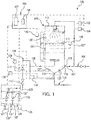
- FIG. 1 an illustrative view of an embodiment of a discharge system in accordance with the disclosure is shown in Fig. 1 and is designated generally by reference character 100.
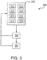
- FIG. 2-3 Other embodiments and/or aspects of this disclosure are shown in Figures 2-3 .
- the systems and methods described herein can be used to mix one or more soluble gas or gas and liquid feedstocks with a solvent, for example, saltwater, and discharge the solution with a known gas solubility saturation level such that the saturation level of gas in the liquid is well below that of typical bubble formation when released. This minimizes potential bubble formation from turbulent conditions or thermal hotspots after release.
- a discharge system 100 includes a mixing vessel 102 and a feedstock input line 104 defining a feedstock flow path 108 in fluid communication with mixing vessel 102.
- a solvent input 106 is in fluid communication with mixing vessel 102.
- a discharge output 110 is in fluid communication with an outlet 112 of the mixing vessel 102.
- Feedstock valves 114 and 114' are on feedstock input line 104 to control the flow of a feedstock, e.g. a gas or gas-fluid mixture, being fed into mixing vessel 102 to dissolve within a solvent thereby generating an effluent discharge solution having a known gas solubility saturation.
- Feedstock input line 104 is operatively connected to multiple feedstock tanks 135, 135' and 135".
- Discharge system 100 includes a controller 101 configured to be operatively connected to each valve 114 and 114'.
- Valves 114 and 114' provide redundancy for feedstock flow shutoff and balance wear.
- valve 114 can cycle in accordance with a duty cycle control law, described below, while valve 114' can be held open. This continues throughout a discharge event, e.g. when the feedstock is flowing into mixing vessel 102. At the start of the next discharge event, or in switching to another feedstock, the roles of valves 114 and 114' are switched, balancing the wear between valves 114 and 114'.
- controller 101 includes a processor 103 operatively connected to a memory 105, wherein memory 105 includes instructions recorded thereon that, when read by processor 103, cause processor 103 to perform a method described below.
- Discharge system 100 includes a differential pressure (dP) sensor 116 operatively connected between the feedstock input line 104 and the discharge output 110 to measure the dP between the feedstock input line 104 and the discharge output 110.
- Pressure sensor 116 is operatively connected to controller 101 to provide the dP data thereto.
- Mixing vessel 102 includes a nozzle 118 proximate to a first side 117 of mixing vessel 102.
- Solvent input 106 is operatively connected to nozzle 118 to direct a solvent toward a gas pocket 120 generated by the gas entering with the feedstock through the feedstock input line 104 as gas or gas-liquid feedstock during the discharge event.
- Solvent input 106 is split into two lines 107 and 107'.
- Line 107 defines a flow path to mixing vessel 102 through an inlet 128 on a second side 119 of mixing vessel 102.
- Line 107' defines a flow path to mixing vessel 102 through nozzle 118.
- Discharge system 100 includes pressure sensors 131, 131', 131" for each feedstock tank 135, 135', 135" upstream of valve 114' to measure pressure of each feedstock at its source.
- Pressure sensor 130 is operatively connected in the feedstock input line 104 between feedstock source selector valves 132, 132', 132" and valve 114'.
- Sensor 130, each of pressure sensors 131, 131', 131", and each feedstock valve 132, 132', 132" are operatively connected to controller 101.
- feedstock tanks 135, 135', 135' are shown, it is contemplated that any number of feedstock tanks 135, 135', 135", and, in turn, any number of feedstock sources, can be used.
- Discharge system 100 includes a solvent temperature sensor 122 operatively connected to solvent input line 107' to provide a temperature reading to controller 101.
- Discharge system 100 includes a solvent pressure sensor 124 operatively connected to solvent input line 107' to provide a solvent pressure reading to controller 101.
- System 100 includes a mixing vessel level sensor 126 operatively connected to mixing vessel 102 and to controller 101 to provide level measurements of the liquid in mixing vessel 102 to determine the desired liquid displacement needed in order to achieve or maintain an optimal liquid level in mixing vessel 102.
- a method 200 for controlling the saturation level of gas in a liquid discharge includes determining baseline data by performing lab or field tests under a fixed set of conditions, and determining theoretical solubility and flow kinetics for a variety of feedstock sources, e.g. those stored in respective feedstock tanks 135, 135', 135', as a function of the temperature and pressure of each feedstock, as shown by box 201.
- Baseline data and theoretical solubility and flow kinetics can be stored in memory 105.
- Method 200 adjusts valve cycle timing during continuous operation, and minimizes pressure spikes in the mixing vessel during initiation of the roiling turbulence to achieve maximum uptake rate.
- roiling turbulence is induced when a gas pocket grows large enough for the nozzle spray to be surrounded by mostly gas.
- the high velocity liquid exiting nozzle 118 entrains some surrounding gas, which is then carried into a liquid surface 113 of bulk liquid 121.
- the momentum of the liquid spray plus the entrained gas then creates the roiling surface conditions.
- method 200 operates without needing immediate feedback.
- Method 200 includes obtaining temperature and pressure measurements of a solvent in a mixing vessel, e.g. mixing vessel 102, and obtaining a pressure measurement of a plurality of feedstock sources in respective feedstock tanks, e.g. feedstock tanks 135, 135', 135", as indicated by box 202.
- Temperature and pressure measurements for the solvent are obtained by controller 101 through temperature and pressure sensors, 122 and 124.
- the pressure measurement for each feedstock is obtained by controller 101 through respective pressure sensors 131, 131', 131".
- Method 200 includes correlating the temperature and pressure measurements of the solvent and the pressure measurement of each of the feedstock sources to the baseline data stored in memory 105 to generate a theoretical uptake rate for each feedstock within the mixing vessel and theoretical flow rate of feedstock into the mixing vessel, as indicated by box 204. It is contemplated that the theoretical uptake rate and the theoretical flow rate can be adjusted by continuously correlating the solvent temperature and pressure, and the pressure measurement of each feedstock source to the baseline data, shown by box 201, to update or reconfirm the theoretical uptake rate and theoretical flow rate.
- Method 200 includes determining a desired liquid, e.g. liquid 121, displacement by determining the actual liquid level in the mixing vessel using a liquid level sensor, e.g. mixing vessel level sensor 126, and comparing the actual liquid level to an optimal liquid level, as indicated by box 206. Determining the actual liquid level is achieved by using a filtered average of measurements from the mixing vessel level sensor.
- the gas is fed into the mixing vessel as a feedstock through a feedstock input line, e.g. feedstock input line 104, and forms a gas pocket, e.g. gas pocket 120, within the mixing vessel.
- method 200 includes determining a required opening setting for a valve, e.g. valves 114 or 114', in the feedstock input line as a function of a flow rate of the feedstock in order to achieve the desired liquid displacement in the mixing vessel due to the feedstock being fed into the mixing vessel, as indicated by box 207.
- the required opening setting can be in the form of a required open duration of the valve for a given cycle, e.g. if the valve is a solenoid valve, and/or the required opening setting can be in the form of a specific flow rate and/or open duration at the given flow rate, e.g. if the valve is metering valve.
- Determining the required opening setting for the valve as a function of the specific flow rate of a given one of the feedstock sources includes determining the pressure within the mixing vessel, determining the pressure of the given feedstock source, the pressure of the feedstock in the feedstock input line, and the type of feedstock, as indicated by box 208.
- the feedstock can be in the form of a gas only feedstock and/or a gas-liquid feedstock.
- Determining the type of feedstock, as indicated by box 208 includes determining whether the feedstock is a gas only feedstock or whether the gas is a gas-liquid feedstock, as well as the type of gases and liquids of each feedstock, and determining which theoretical and adjustment data sets currently apply. It also determines which of the feedstock source isolation valves, e.g. feedstock source selector valves 132, 132', 132", are to be used.
- each feedstock source is separately characterized. Additionally, it is contemplated that when there are multiple feedstock sources, a priority scheme is set such that the higher priority feedstock source interrupts lower priority feedstock discharge. Flow from the lower priority feedstock source is stopped and feed calculations based upon the higher priority feedstock are computed and used until that feedstock's discharge limits are met, and then controller 101 resumes discharge of the lower priority feedstock.
- Method 200 operates to lower the liquid level with short cycles of feedstock flow by opening valves 114, 114', and at least one of valves 132, 132' and 132", which add gas, until the optimal liquid level is reached. Over time, if the liquid level continues to drop, the valve "ON" duty cycle times are shortened, and if the level rises, the valve "ON" pulses or durations are increased. It is also contemplated that method 200 includes hard safety stops exist so that mixing vessel 102, always has a sufficiently low gas to liquid ratio to prevent accidental discharge of bubbles during rapid ascent.
- method 200 can still include adding feedstock to the mixing vessel. To minimize the size of mixing vessel 102 and minimize the flow rate of the solvent, both of which impact the volume and power required to achieve a given level of effluent gas disposal, it is desired to continually supply feedstock during all maneuvers of the vehicle, including ascent.
- Controller 101 utilizes the required opening setting to generate a valve operating control law, described below, without real time feedback of level sensor readings. This means that the actual solvent displacement for a given valve opening setting is not dependent upon the closed loop of activate/sense/deactivate steps found in a typical control system, making the system operationally insensitive to vehicle pitch and roll, and the effects of the roiling surface of the liquid within the mixing vessel, all of which might cause faulty mixing vessel liquid level measurement in traditional systems.
- method 200 includes determining an uptake duration for the given feedstock source to uptake into the solvent to form an effluent discharge solution and achieving an uptake displacement equivalent to the reverse of the desired liquid displacement based on the baseline uptake rate.
- Method 200 includes generating a valve operating control law for how long the valve should be opened in a cycle, as indicated by box 210, based on the required opening setting to supply feedstock as determined in box 207, and the uptake duration for the desired liquid displacement of the feedstock being processed.
- Method 200 makes continuous adjustments to the valve operating control law based on pressure and temperature changes.
- Method 200 is a closed loop control method without immediate feedback, making the valve operating control law insensitive to noise in a discharge system, e.g. discharge system 100, such as, communications errors, intermittent loss of feedback signal, and inconsistencies due to pitch and roll. This insensitivity provides robust operation at startup, shutdown, and under transient conditions, and maintains high performance with wide pressure tolerance, and wide temperature tolerance.
- high performance includes near optimal gas discharge saturation level under all temperature and pressure conditions, operation during all maneuvers of the vehicle, and elimination of all risk that some bubbles may escape in the discharge fluid due to a low liquid level in the mixing vessel 102, thereby causing suctioning of gas out of the outlet of the mixing vessel, e.g. outlet 112.
- Method 200 includes commanding at least one of the source selector valves, e.g. source selector valves 132, 132', 132", and the feedstock valves, e.g. feedstock valves 114 and 114', to meter flow rate based on the valve operating control law, as shown by box 212.
- metering flow rate includes commanding the valves to open and close for a specific duration, and/or includes metering the flow rate through the valves, depending on the type of valve used. This allows feedstock to flow into the mixing vessel 102 from the feedstock input line 104 and dissolve within the solvent to generate the effluent discharge solution having a known gas solubility saturation.
- Method 200 includes determining an optimal liquid level within the mixing vessel and commanding at least one of the source selector valves and the feedstock valve to maintain the optimal liquid level to maintain the desired turbulence at the interface between the gas pocket and the solvent within the mixing vessel, as indicated by box 214.
- the control further utilizes measurements to maintain a level near the optimal uptake rate within the mixing vessel, which is another constant independently determined by the theoretical flow calculations of box 204 for the feedstock, the theoretical calculations of uptake of the feedstock determined in box 207, and the normalization of the two calculations to obtain the control law for valves 114 and 114', determined in box 212.
- Method 200 includes discharging the effluent discharge solution from the mixing vessel and determining the actual flow of the effluent discharge solution discharged from the mixing vessel, as indicated by box 216. Method 200 also includes dynamically adjusting the theoretical computations 214 and 216 from data received regarding the filtered average of measurements from the mixing vessel level sensor.
- liquid feedstock e.g. the gas-fluid mixture
- valves 114, 114', 132, 132', 132 are sequenced with much shorter cycles to gently "push” any liquid along and into the mixing vessel.
- feedstock might be accelerated along the line between one or more of feedstock source isolation valves 132, 132', 132", and the control valves 114 and 114'. Then, since liquid flow carries much more momentum, and also moves more slowly, either valve 114 or 114' might cycle shut as the liquid begins to pass through the valve, creating acoustically noisy and potentially damaging "water hammer” pressure spike. By initially "flushing" the liquid, water hammer effects are prevented.
- any gas-liquid mixed feedstock is supplied at 100% saturation at an elevated pressure because: a) the gas and liquid were either co-formed, or stored long enough in a static vessel, such that enough time had lapsed that the solubility reached equilibrium, and b) the upstream pressure needs to be higher just to create flow.
- discharge system 100 and method 200 are capable of reducing the gas pocket level in mixing vessel 102 by 0.5 inch every 3 to 10 seconds, at the worst case temperature and pressure. At colder and deeper conditions, this rate may increase, but the design is relatively insensitive to pressure changes up to relatively high pressure.
- feed rates from a feedstock input line 104 are relatively low since the delta pressure is much lower and typically less than a 2:1 ratio, so sonic flow does not exist.
- the kinetic uptake rate and bulk solubility of a feedstock gas in the solvent is such that adding feedstock may not change the level within the mixing vessel.
- Mixing vessel 102, solvent flow rate, and required discharge pressure drop are all sized for the worst case shallow/warmest solvent temperature. Typical systems may have a dynamic range of more than 20:1 as compared with the deep or high pressure, cold solvent case.
- method 200 includes monitoring discharge pressure drop with a pressure sensor, e.g. differential pressure sensor 116, operatively connected between the feedstock input line and a discharge output, e.g. discharge output 110, as an added diagnostic capability with potential control system value in preventing gas bubble discharge to off nominal conditions.
- a pressure sensor e.g. differential pressure sensor 116
- discharge output 110 e.g. discharge output 110
- Method 300 includes specific tests to assure that the two main solenoid valves, e.g. 114 and 114', of system 100 shut and open properly, that source feedstock flows when open, and that feedstock does not flow when closed. Method 300 also detects low or zero solute flow, detects operator error in valve alignment for overboard discharge, and detects other failures which prevent proper discharge of bubble less effluent. Method 300 includes determining whether the discharge system conditions are normal or abnormal, as indicated by box 310. Discharge system conditions include a desired solvent flow, a desired feedstock flow, a pressure in the mixing vessel, operation of the feedstock valve, and/or operation of sensors.
- method 300 includes sending a signal indicative of abnormal function if any of the system conditions are abnormal and sending a signal indicative normal function if all of the system conditions are normal, as indicated by box 320.
- Method 300 includes pausing operation the discharge system off if the signal indicative of abnormal function is sent to avoid bubble discharge from the discharge output during abnormal system conditions, as indicated by box 330.
- mixing vessel 102 includes two independent level switches 137 and 137'. Each level switch 137 and 137' is wired to a respective solenoid drive circuit 139 and 139' for respective feedstock valve 114 and 114'.
- determining whether the discharge system conditions are normal or abnormal includes determining whether there is solvent in the mixing vessel by retrieving a signal from the level switch that indicates a dry or wet position, as indicated by box 311. If the level switch is in the dry position, and at least one of the solenoid drive circuit is energized, or the feedstock valve is open, the system conditions are abnormal.
- determining whether the discharge system conditions are normal or abnormal includes verifying that a desired solvent flow is occurring by measuring differential pressure (dP) across the discharge output with a dP sensor and comparing the measured dP to a reference dP threshold range, and determining that the discharge system conditions are abnormal if the dP is outside of the dP threshold range, as indicated by box 312.
- Verifying that the desired solvent flow is occurring includes calibrating the dP threshold range to account for a dP pattern when feedstock is added to the mixing vessel. For example, when feedstock is added to the mixer, the dP generally should spike, level off, and abate when the feed is stopped.
- Verifying that the desired solvent flow is occurring includes verifying that the dP sensor is operating properly by determining dP as a function of vessel pressure and feedstock type. For example, during operation, the solvent level in mixing vessel is a function of the feedstock and various operating pressures. Proper operation of the sensor is also verified as a function of pressure and feedstock type. Additionally, during operation, uptake of feedstock, as measured by a rise in level, verifies solute flow. Failures of any of these tests results in appropriate operator signals, and pause or full shutdown of the system.
- determining whether the discharge system conditions are normal or abnormal includes determining whether the feedstock source control valve is operating, as indicated by box 313.
- each feedstock source selector valve 132, 132', and 132" is opened singly, and both dP and mixing vessel pressure is measured to detect any feedstock flow. This verifies that none of valves 132, 132' and 132" leak. Then, with one valve open, the other is short cycled and pressures are again measured, to assure that flow occurs, and then stops when the short cycle ends.
- determining whether the discharge system conditions are normal or abnormal includes monitoring mixing vessel pressure with a mixing vessel pressure sensor 140 and determining the discharge conditions are abnormal if the mixing vessel pressure exceeds a pre-determined warning threshold. It is also contemplated that, even in a 'pause' scenario, if the mixing vessel pressure exceeds a shutdown threshold, the system is automatically shut down. Moreover, feedstock pressures for some source feedstocks may exceed the vehicle or structures fluid pumping and discharge design levels. Those skilled in the art will readily appreciate that specific warning and shutdown set points can also be established for feedstock pressures.
- Determining whether the discharge system conditions are normal or abnormal includes checking the status of the dP sensor when only the feedstock is flowing by comparing the measured rise in dP to an expected dP rise band, and determining the discharge conditions are abnormal if the measured dP is outside of the expected dP rise band, as indicated in box 316.
- Determining whether the discharge system conditions are normal or abnormal includes checking the status of a mixer temperature sensor by comparing a measured mixer temperature to an expected mixer temperature band, and determining the discharge conditions are abnormal if the measured mixer temperature is outside of the expected mixer temperature band, as indicated by box 317.
- determining whether the discharge system conditions are normal or abnormal includes checking a status of a mixing vessel level sensor, as indicated by box 318.
- checking the status of the mixing vessel level sensor includes comparing a measured mixing vessel level to an expected mixing vessel level threshold. If the measured mixing vessel level is lower than the expected mixing vessel level threshold, the discharge conditions are abnormal.
- checking the status of the mixing vessel level sensor includes measuring a change in mixing vessel level and comparing the change in mixing vessel level with an expected mixing vessel level change. If the measured mixing vessel level change is lower than the expected mixing vessel level threshold, the discharge conditions are abnormal.
- the expected mixing vessel level change is a function of feedstock type and an expected gas uptake rate.
Landscapes
- Engineering & Computer Science (AREA)
- Chemical & Material Sciences (AREA)
- Chemical Kinetics & Catalysis (AREA)
- Mechanical Engineering (AREA)
- General Engineering & Computer Science (AREA)
- Combustion & Propulsion (AREA)
- Physics & Mathematics (AREA)
- General Physics & Mathematics (AREA)
- Automation & Control Theory (AREA)
- Aviation & Aerospace Engineering (AREA)
- Accessories For Mixers (AREA)
- Extraction Or Liquid Replacement (AREA)
- Control Of Non-Electrical Variables (AREA)
Applications Claiming Priority (1)
| Application Number | Priority Date | Filing Date | Title |
|---|---|---|---|
| US14/868,094 US10300439B2 (en) | 2015-09-28 | 2015-09-28 | Systems and methods for gas disposal |
Publications (3)
| Publication Number | Publication Date |
|---|---|
| EP3147745A2 true EP3147745A2 (de) | 2017-03-29 |
| EP3147745A3 EP3147745A3 (de) | 2017-07-12 |
| EP3147745B1 EP3147745B1 (de) | 2020-08-19 |
Family
ID=57391735
Family Applications (1)
| Application Number | Title | Priority Date | Filing Date |
|---|---|---|---|
| EP16191067.4A Active EP3147745B1 (de) | 2015-09-28 | 2016-09-28 | System und verfahren zur gasentsorgung |
Country Status (2)
| Country | Link |
|---|---|
| US (3) | US10300439B2 (de) |
| EP (1) | EP3147745B1 (de) |
Families Citing this family (4)
| Publication number | Priority date | Publication date | Assignee | Title |
|---|---|---|---|---|
| US10589237B2 (en) * | 2015-09-28 | 2020-03-17 | Hamilton Sundstrand Corporation | Systems and methods for gas disposal |
| KR101959401B1 (ko) * | 2017-05-18 | 2019-07-05 | 주식회사 파나시아 | 배기가스 처리장치의 배출 세정액 내의 유해가스 제거 시스템 및 방법 |
| CN112973383A (zh) * | 2019-12-14 | 2021-06-18 | 中国科学院大连化学物理研究所 | 一种水下用燃料电池尾气排放系统 |
| WO2023067558A1 (en) | 2021-10-22 | 2023-04-27 | Fisher & Paykel Healthcare Limited | Patient interface |
Family Cites Families (34)
| Publication number | Priority date | Publication date | Assignee | Title |
|---|---|---|---|---|
| US2594880A (en) | 1949-11-01 | 1952-04-29 | Lummus Co | Purification of oils by clay contacting |
| US3425669A (en) | 1967-11-13 | 1969-02-04 | Preston G Gaddis | Dry chemical feeder method and apparatus |
| US4022694A (en) | 1974-05-06 | 1977-05-10 | Hydronautics, Incorporated | Oil-water separation apparatus |
| US4850269A (en) | 1987-06-26 | 1989-07-25 | Aquatec, Inc. | Low pressure, high efficiency carbonator and method |
| NL9001805A (nl) | 1990-08-10 | 1991-01-02 | Landbouwmechanisatiebedrijf B | Werkwijze en inrichting voor het mengen van vloeistof en gas, in het bijzonder ijzerhoudend water en lucht. |
| ES2107316T3 (es) | 1994-09-10 | 1997-11-16 | Bernd Ch Tlok | Procedimiento para la filtracion de agua y dispositivo para la realizacion del mismo. |
| CA2160412A1 (en) | 1994-10-13 | 1996-04-14 | Adolf Frederik Scheybeler | Method and apparatus for degassing sulphur |
| US6123750A (en) | 1998-10-30 | 2000-09-26 | New England Radon, Ltd | Spray and aeration system for removing volatile compounds |
| US6406539B1 (en) | 1999-04-28 | 2002-06-18 | Showa Denko K.K, | Process for producing silicon carbide single crystal and production apparatus therefor |
| JP4002439B2 (ja) | 1999-11-15 | 2007-10-31 | 株式会社オ−ラテック | マイクロバブル発生ノズル及びその応用装置 |
| US6712215B2 (en) | 2000-07-28 | 2004-03-30 | Adolf Frederik Scheybeler | Method and apparatus for recovery of lost diluent in oil sands extraction tailings |
| DE10061487C1 (de) | 2000-12-09 | 2002-03-21 | Howaldtswerke Deutsche Werft | Verfahren zum signaturfreien Ausbringen von Abgas aus Unterwasserfahrzeugen |
| US7105039B2 (en) | 2003-02-26 | 2006-09-12 | Scott Decker | Ozone remediation apparatus and methods |
| NO20034330D0 (no) | 2003-09-26 | 2003-09-26 | Norsk Hydro As | Fremgangsmåte for blanding av to fluider og mikser for utövelse av slik fremgangsmåte |
| US20050145498A1 (en) | 2003-12-31 | 2005-07-07 | Clark James R. | Apparatus and method for treating used electroless plating solutions |
| US7230034B2 (en) | 2004-03-19 | 2007-06-12 | Conocophillips Company | Prevention of and recovering from a catalyst bed slumping in a gas-agitated multiphase reactor |
| US7255332B2 (en) | 2004-05-25 | 2007-08-14 | The Board Of Trustees Of The University Of Arkansas | System and method for dissolving gases in liquids |
| US9248415B2 (en) | 2004-05-25 | 2016-02-02 | Board Of Trustees Of The University Of Arkansas | Systems and methods for maximizing dissolved gas concentration of a single species of gas from a mixture of multiple gases |
| WO2006060897A1 (en) | 2004-12-10 | 2006-06-15 | University Of Manitoba | Bubble-less gas delivery into liquid systems |
| US7829750B2 (en) | 2004-12-30 | 2010-11-09 | Exxonmobil Chemical Patents Inc. | Fluidizing a population of catalyst particles having a low catalyst fines content |
| DE102005007484A1 (de) | 2005-01-25 | 2006-07-27 | Siemens Ag | U-Boot mit Unterwasser-Abgasausleitung bei Schnorchelfahrt |
| US8246564B2 (en) | 2008-12-04 | 2012-08-21 | Therox, Inc. | System for enriching a bodily fluid with a gas having automated priming capabilities |
| WO2010092569A1 (en) | 2009-02-10 | 2010-08-19 | Diffusair Ltd. | Device and method for dissolving gas into a liquid |
| US8440006B2 (en) | 2009-08-21 | 2013-05-14 | Alstom Technology Ltd | System and method for flue gas scrubbing |
| DE102009051308A1 (de) | 2009-10-29 | 2011-05-05 | Howaldtswerke-Deutsche Werft Gmbh | Unterseeboot mit einer Anlage zur Ausbringung von Gas |
| DE102010007559B4 (de) | 2010-02-10 | 2014-01-09 | Sartorius Stedim Biotech Gmbh | Bioreaktorbehälter mit einem optischen Schaumsensor |
| US9725688B2 (en) | 2011-06-30 | 2017-08-08 | Peter Simpson Bell | Bioreactor for syngas fermentation |
| PT2719440T (pt) | 2012-10-15 | 2017-06-26 | Linde Ag | Método para remover contaminantes de gases de exaustão por adição de ozono |
| US8980085B1 (en) | 2012-11-27 | 2015-03-17 | Adrian A. Preiss | Ozone dissolution chamber |
| WO2014145661A1 (en) | 2013-03-15 | 2014-09-18 | Pentair Water Pool And Spa, Inc. | Dissolved oxygen control system for aquaculture |
| US9617509B2 (en) | 2013-07-29 | 2017-04-11 | Lanzatech New Zealand Limited | Fermentation of gaseous substrates |
| US9050557B1 (en) | 2014-05-30 | 2015-06-09 | Gas Technology Institute | Scavenging and tailgas process |
| US9545614B2 (en) | 2015-03-13 | 2017-01-17 | Chevron U.S.A. Inc. | Pneumatically agitated ionic liquid alkylation using vaporization to remove reaction heat |
| US10589237B2 (en) * | 2015-09-28 | 2020-03-17 | Hamilton Sundstrand Corporation | Systems and methods for gas disposal |
-
2015
- 2015-09-28 US US14/868,094 patent/US10300439B2/en active Active
-
2016
- 2016-09-28 EP EP16191067.4A patent/EP3147745B1/de active Active
-
2019
- 2019-04-22 US US16/391,235 patent/US10898866B2/en active Active
-
2021
- 2021-01-13 US US17/148,068 patent/US11504676B2/en active Active
Non-Patent Citations (1)
| Title |
|---|
| None |
Also Published As
| Publication number | Publication date |
|---|---|
| US10300439B2 (en) | 2019-05-28 |
| US20200222861A1 (en) | 2020-07-16 |
| EP3147745B1 (de) | 2020-08-19 |
| US20170087521A1 (en) | 2017-03-30 |
| EP3147745A3 (de) | 2017-07-12 |
| US11504676B2 (en) | 2022-11-22 |
| US10898866B2 (en) | 2021-01-26 |
| US20210362102A1 (en) | 2021-11-25 |
Similar Documents
| Publication | Publication Date | Title |
|---|---|---|
| US11504676B2 (en) | Systems and methods for gas disposal | |
| US11826713B2 (en) | Systems and methods for generating a conductive liquid comprising deionized water with ammonia gas dissolved therein | |
| US8307845B2 (en) | Flow rate controller | |
| US20080257738A1 (en) | Devices, Systems, and Methods for Carbonation of Deionized Water | |
| US7703543B2 (en) | Fire fighting foam dispensing system and related method | |
| WO2011153056A1 (en) | Devices, systems, and methods for carbonation of deionized water | |
| KR102087773B1 (ko) | 액체 혼합 공급장치 | |
| JP2009198472A (ja) | 高圧ガス流量計測装置及び流量計測方法 | |
| JP4782180B2 (ja) | 泡消火薬剤混合システム | |
| JP6577267B2 (ja) | ガス検知システム | |
| KR101762777B1 (ko) | 공기윤활장치를 포함하는 선박 | |
| KR101511710B1 (ko) | 부스터 펌프 시스템 및 부스터 펌프의 제어방법 | |
| CN110836746B (zh) | 封闭管路内的水流安全检测方法及装置 | |
| JP3875596B2 (ja) | 機能性超純水の製造方法及びそれに用いる装置 | |
| RU2473050C1 (ru) | Устройство для дозирования флотационных реагентов | |
| US20150323365A1 (en) | Flow meter device | |
| EP3971538B1 (de) | Gassicherheitsvorrichtung | |
| JP2020040009A (ja) | ガス発生器 | |
| KR200438619Y1 (ko) | 수격방지용 에어챔버 시스템 | |
| JP2007000739A (ja) | 散気システム | |
| KR20160010099A (ko) | 유량 제어 장치 | |
| JP4296915B2 (ja) | ガス遮断装置 | |
| JP6949780B2 (ja) | パージ方法、パージのための制御装置、および制御装置を備えるシステム | |
| KR200161187Y1 (ko) | 관내 유속 검출에 의한 비상유체 차단장치 | |
| JPH09318408A (ja) | ガスメータ |
Legal Events
| Date | Code | Title | Description |
|---|---|---|---|
| PUAI | Public reference made under article 153(3) epc to a published international application that has entered the european phase |
Free format text: ORIGINAL CODE: 0009012 |
|
| STAA | Information on the status of an ep patent application or granted ep patent |
Free format text: STATUS: THE APPLICATION HAS BEEN PUBLISHED |
|
| AK | Designated contracting states |
Kind code of ref document: A2 Designated state(s): AL AT BE BG CH CY CZ DE DK EE ES FI FR GB GR HR HU IE IS IT LI LT LU LV MC MK MT NL NO PL PT RO RS SE SI SK SM TR |
|
| AX | Request for extension of the european patent |
Extension state: BA ME |
|
| PUAL | Search report despatched |
Free format text: ORIGINAL CODE: 0009013 |
|
| AK | Designated contracting states |
Kind code of ref document: A3 Designated state(s): AL AT BE BG CH CY CZ DE DK EE ES FI FR GB GR HR HU IE IS IT LI LT LU LV MC MK MT NL NO PL PT RO RS SE SI SK SM TR |
|
| AX | Request for extension of the european patent |
Extension state: BA ME |
|
| RIC1 | Information provided on ipc code assigned before grant |
Ipc: F01N 13/12 20100101ALI20170602BHEP Ipc: G05D 21/02 20060101AFI20170602BHEP Ipc: B63G 8/08 20060101ALI20170602BHEP Ipc: B01F 3/04 20060101ALI20170602BHEP |
|
| STAA | Information on the status of an ep patent application or granted ep patent |
Free format text: STATUS: REQUEST FOR EXAMINATION WAS MADE |
|
| 17P | Request for examination filed |
Effective date: 20180111 |
|
| RBV | Designated contracting states (corrected) |
Designated state(s): AL AT BE BG CH CY CZ DE DK EE ES FI FR GB GR HR HU IE IS IT LI LT LU LV MC MK MT NL NO PL PT RO RS SE SI SK SM TR |
|
| GRAP | Despatch of communication of intention to grant a patent |
Free format text: ORIGINAL CODE: EPIDOSNIGR1 |
|
| STAA | Information on the status of an ep patent application or granted ep patent |
Free format text: STATUS: GRANT OF PATENT IS INTENDED |
|
| RIC1 | Information provided on ipc code assigned before grant |
Ipc: F01N 13/12 20100101ALI20200124BHEP Ipc: B01F 3/04 20060101ALI20200124BHEP Ipc: B63G 8/08 20060101ALI20200124BHEP Ipc: G05D 21/02 20060101AFI20200124BHEP Ipc: B01F 15/00 20060101ALI20200124BHEP |
|
| INTG | Intention to grant announced |
Effective date: 20200228 |
|
| GRAS | Grant fee paid |
Free format text: ORIGINAL CODE: EPIDOSNIGR3 |
|
| GRAA | (expected) grant |
Free format text: ORIGINAL CODE: 0009210 |
|
| STAA | Information on the status of an ep patent application or granted ep patent |
Free format text: STATUS: THE PATENT HAS BEEN GRANTED |
|
| AK | Designated contracting states |
Kind code of ref document: B1 Designated state(s): AL AT BE BG CH CY CZ DE DK EE ES FI FR GB GR HR HU IE IS IT LI LT LU LV MC MK MT NL NO PL PT RO RS SE SI SK SM TR |
|
| REG | Reference to a national code |
Ref country code: CH Ref legal event code: EP |
|
| REG | Reference to a national code |
Ref country code: DE Ref legal event code: R096 Ref document number: 602016042162 Country of ref document: DE |
|
| REG | Reference to a national code |
Ref country code: AT Ref legal event code: REF Ref document number: 1304682 Country of ref document: AT Kind code of ref document: T Effective date: 20200915 |
|
| REG | Reference to a national code |
Ref country code: IE Ref legal event code: FG4D |
|
| REG | Reference to a national code |
Ref country code: LT Ref legal event code: MG4D |
|
| REG | Reference to a national code |
Ref country code: NL Ref legal event code: MP Effective date: 20200819 |
|
| PG25 | Lapsed in a contracting state [announced via postgrant information from national office to epo] |
Ref country code: GR Free format text: LAPSE BECAUSE OF FAILURE TO SUBMIT A TRANSLATION OF THE DESCRIPTION OR TO PAY THE FEE WITHIN THE PRESCRIBED TIME-LIMIT Effective date: 20201120 Ref country code: FI Free format text: LAPSE BECAUSE OF FAILURE TO SUBMIT A TRANSLATION OF THE DESCRIPTION OR TO PAY THE FEE WITHIN THE PRESCRIBED TIME-LIMIT Effective date: 20200819 Ref country code: PT Free format text: LAPSE BECAUSE OF FAILURE TO SUBMIT A TRANSLATION OF THE DESCRIPTION OR TO PAY THE FEE WITHIN THE PRESCRIBED TIME-LIMIT Effective date: 20201221 Ref country code: SE Free format text: LAPSE BECAUSE OF FAILURE TO SUBMIT A TRANSLATION OF THE DESCRIPTION OR TO PAY THE FEE WITHIN THE PRESCRIBED TIME-LIMIT Effective date: 20200819 Ref country code: NO Free format text: LAPSE BECAUSE OF FAILURE TO SUBMIT A TRANSLATION OF THE DESCRIPTION OR TO PAY THE FEE WITHIN THE PRESCRIBED TIME-LIMIT Effective date: 20201119 Ref country code: BG Free format text: LAPSE BECAUSE OF FAILURE TO SUBMIT A TRANSLATION OF THE DESCRIPTION OR TO PAY THE FEE WITHIN THE PRESCRIBED TIME-LIMIT Effective date: 20201119 Ref country code: LT Free format text: LAPSE BECAUSE OF FAILURE TO SUBMIT A TRANSLATION OF THE DESCRIPTION OR TO PAY THE FEE WITHIN THE PRESCRIBED TIME-LIMIT Effective date: 20200819 Ref country code: HR Free format text: LAPSE BECAUSE OF FAILURE TO SUBMIT A TRANSLATION OF THE DESCRIPTION OR TO PAY THE FEE WITHIN THE PRESCRIBED TIME-LIMIT Effective date: 20200819 |
|
| REG | Reference to a national code |
Ref country code: AT Ref legal event code: MK05 Ref document number: 1304682 Country of ref document: AT Kind code of ref document: T Effective date: 20200819 |
|
| PG25 | Lapsed in a contracting state [announced via postgrant information from national office to epo] |
Ref country code: PL Free format text: LAPSE BECAUSE OF FAILURE TO SUBMIT A TRANSLATION OF THE DESCRIPTION OR TO PAY THE FEE WITHIN THE PRESCRIBED TIME-LIMIT Effective date: 20200819 Ref country code: RS Free format text: LAPSE BECAUSE OF FAILURE TO SUBMIT A TRANSLATION OF THE DESCRIPTION OR TO PAY THE FEE WITHIN THE PRESCRIBED TIME-LIMIT Effective date: 20200819 Ref country code: LV Free format text: LAPSE BECAUSE OF FAILURE TO SUBMIT A TRANSLATION OF THE DESCRIPTION OR TO PAY THE FEE WITHIN THE PRESCRIBED TIME-LIMIT Effective date: 20200819 Ref country code: NL Free format text: LAPSE BECAUSE OF FAILURE TO SUBMIT A TRANSLATION OF THE DESCRIPTION OR TO PAY THE FEE WITHIN THE PRESCRIBED TIME-LIMIT Effective date: 20200819 Ref country code: IS Free format text: LAPSE BECAUSE OF FAILURE TO SUBMIT A TRANSLATION OF THE DESCRIPTION OR TO PAY THE FEE WITHIN THE PRESCRIBED TIME-LIMIT Effective date: 20201219 |
|
| PG25 | Lapsed in a contracting state [announced via postgrant information from national office to epo] |
Ref country code: SM Free format text: LAPSE BECAUSE OF FAILURE TO SUBMIT A TRANSLATION OF THE DESCRIPTION OR TO PAY THE FEE WITHIN THE PRESCRIBED TIME-LIMIT Effective date: 20200819 Ref country code: RO Free format text: LAPSE BECAUSE OF FAILURE TO SUBMIT A TRANSLATION OF THE DESCRIPTION OR TO PAY THE FEE WITHIN THE PRESCRIBED TIME-LIMIT Effective date: 20200819 Ref country code: CZ Free format text: LAPSE BECAUSE OF FAILURE TO SUBMIT A TRANSLATION OF THE DESCRIPTION OR TO PAY THE FEE WITHIN THE PRESCRIBED TIME-LIMIT Effective date: 20200819 Ref country code: DK Free format text: LAPSE BECAUSE OF FAILURE TO SUBMIT A TRANSLATION OF THE DESCRIPTION OR TO PAY THE FEE WITHIN THE PRESCRIBED TIME-LIMIT Effective date: 20200819 Ref country code: EE Free format text: LAPSE BECAUSE OF FAILURE TO SUBMIT A TRANSLATION OF THE DESCRIPTION OR TO PAY THE FEE WITHIN THE PRESCRIBED TIME-LIMIT Effective date: 20200819 |
|
| REG | Reference to a national code |
Ref country code: CH Ref legal event code: PL |
|
| REG | Reference to a national code |
Ref country code: DE Ref legal event code: R097 Ref document number: 602016042162 Country of ref document: DE |
|
| PG25 | Lapsed in a contracting state [announced via postgrant information from national office to epo] |
Ref country code: ES Free format text: LAPSE BECAUSE OF FAILURE TO SUBMIT A TRANSLATION OF THE DESCRIPTION OR TO PAY THE FEE WITHIN THE PRESCRIBED TIME-LIMIT Effective date: 20200819 Ref country code: AL Free format text: LAPSE BECAUSE OF FAILURE TO SUBMIT A TRANSLATION OF THE DESCRIPTION OR TO PAY THE FEE WITHIN THE PRESCRIBED TIME-LIMIT Effective date: 20200819 Ref country code: AT Free format text: LAPSE BECAUSE OF FAILURE TO SUBMIT A TRANSLATION OF THE DESCRIPTION OR TO PAY THE FEE WITHIN THE PRESCRIBED TIME-LIMIT Effective date: 20200819 Ref country code: MC Free format text: LAPSE BECAUSE OF FAILURE TO SUBMIT A TRANSLATION OF THE DESCRIPTION OR TO PAY THE FEE WITHIN THE PRESCRIBED TIME-LIMIT Effective date: 20200819 |
|
| REG | Reference to a national code |
Ref country code: BE Ref legal event code: MM Effective date: 20200930 |
|
| PLBE | No opposition filed within time limit |
Free format text: ORIGINAL CODE: 0009261 |
|
| STAA | Information on the status of an ep patent application or granted ep patent |
Free format text: STATUS: NO OPPOSITION FILED WITHIN TIME LIMIT |
|
| PG25 | Lapsed in a contracting state [announced via postgrant information from national office to epo] |
Ref country code: LU Free format text: LAPSE BECAUSE OF NON-PAYMENT OF DUE FEES Effective date: 20200928 Ref country code: SK Free format text: LAPSE BECAUSE OF FAILURE TO SUBMIT A TRANSLATION OF THE DESCRIPTION OR TO PAY THE FEE WITHIN THE PRESCRIBED TIME-LIMIT Effective date: 20200819 |
|
| 26N | No opposition filed |
Effective date: 20210520 |
|
| PG25 | Lapsed in a contracting state [announced via postgrant information from national office to epo] |
Ref country code: IT Free format text: LAPSE BECAUSE OF FAILURE TO SUBMIT A TRANSLATION OF THE DESCRIPTION OR TO PAY THE FEE WITHIN THE PRESCRIBED TIME-LIMIT Effective date: 20200819 |
|
| PG25 | Lapsed in a contracting state [announced via postgrant information from national office to epo] |
Ref country code: SI Free format text: LAPSE BECAUSE OF FAILURE TO SUBMIT A TRANSLATION OF THE DESCRIPTION OR TO PAY THE FEE WITHIN THE PRESCRIBED TIME-LIMIT Effective date: 20200819 Ref country code: LI Free format text: LAPSE BECAUSE OF NON-PAYMENT OF DUE FEES Effective date: 20200930 Ref country code: IE Free format text: LAPSE BECAUSE OF NON-PAYMENT OF DUE FEES Effective date: 20200928 Ref country code: CH Free format text: LAPSE BECAUSE OF NON-PAYMENT OF DUE FEES Effective date: 20200930 Ref country code: BE Free format text: LAPSE BECAUSE OF NON-PAYMENT OF DUE FEES Effective date: 20200930 |
|
| PG25 | Lapsed in a contracting state [announced via postgrant information from national office to epo] |
Ref country code: TR Free format text: LAPSE BECAUSE OF FAILURE TO SUBMIT A TRANSLATION OF THE DESCRIPTION OR TO PAY THE FEE WITHIN THE PRESCRIBED TIME-LIMIT Effective date: 20200819 Ref country code: MT Free format text: LAPSE BECAUSE OF FAILURE TO SUBMIT A TRANSLATION OF THE DESCRIPTION OR TO PAY THE FEE WITHIN THE PRESCRIBED TIME-LIMIT Effective date: 20200819 Ref country code: CY Free format text: LAPSE BECAUSE OF FAILURE TO SUBMIT A TRANSLATION OF THE DESCRIPTION OR TO PAY THE FEE WITHIN THE PRESCRIBED TIME-LIMIT Effective date: 20200819 |
|
| PG25 | Lapsed in a contracting state [announced via postgrant information from national office to epo] |
Ref country code: MK Free format text: LAPSE BECAUSE OF FAILURE TO SUBMIT A TRANSLATION OF THE DESCRIPTION OR TO PAY THE FEE WITHIN THE PRESCRIBED TIME-LIMIT Effective date: 20200819 |
|
| P01 | Opt-out of the competence of the unified patent court (upc) registered |
Effective date: 20230522 |
|
| PGFP | Annual fee paid to national office [announced via postgrant information from national office to epo] |
Ref country code: DE Payment date: 20250820 Year of fee payment: 10 |
|
| PGFP | Annual fee paid to national office [announced via postgrant information from national office to epo] |
Ref country code: GB Payment date: 20250827 Year of fee payment: 10 |
|
| PGFP | Annual fee paid to national office [announced via postgrant information from national office to epo] |
Ref country code: FR Payment date: 20250820 Year of fee payment: 10 |