EP3147904B1 - Procédé de détermination de quantités perceptives objectives de signaux de parole bruités - Google Patents
Procédé de détermination de quantités perceptives objectives de signaux de parole bruités Download PDFInfo
- Publication number
- EP3147904B1 EP3147904B1 EP16187961.4A EP16187961A EP3147904B1 EP 3147904 B1 EP3147904 B1 EP 3147904B1 EP 16187961 A EP16187961 A EP 16187961A EP 3147904 B1 EP3147904 B1 EP 3147904B1
- Authority
- EP
- European Patent Office
- Prior art keywords
- noisy speech
- signal
- objective
- hearing instrument
- hearing
- Prior art date
- Legal status (The legal status is an assumption and is not a legal conclusion. Google has not performed a legal analysis and makes no representation as to the accuracy of the status listed.)
- Active
Links
Images


Classifications
-
- H—ELECTRICITY
- H04—ELECTRIC COMMUNICATION TECHNIQUE
- H04R—LOUDSPEAKERS, MICROPHONES, GRAMOPHONE PICK-UPS OR LIKE ACOUSTIC ELECTROMECHANICAL TRANSDUCERS; ELECTRIC HEARING AIDS; PUBLIC ADDRESS SYSTEMS
- H04R29/00—Monitoring arrangements; Testing arrangements
- H04R29/001—Monitoring arrangements; Testing arrangements for loudspeakers
-
- H—ELECTRICITY
- H04—ELECTRIC COMMUNICATION TECHNIQUE
- H04R—LOUDSPEAKERS, MICROPHONES, GRAMOPHONE PICK-UPS OR LIKE ACOUSTIC ELECTROMECHANICAL TRANSDUCERS; ELECTRIC HEARING AIDS; PUBLIC ADDRESS SYSTEMS
- H04R25/00—Electric hearing aids
- H04R25/40—Arrangements for obtaining a desired directivity characteristic
- H04R25/407—Circuits for combining signals of a plurality of transducers
-
- G—PHYSICS
- G10—MUSICAL INSTRUMENTS; ACOUSTICS
- G10L—SPEECH ANALYSIS TECHNIQUES OR SPEECH SYNTHESIS; SPEECH RECOGNITION; SPEECH OR VOICE PROCESSING TECHNIQUES; SPEECH OR AUDIO CODING OR DECODING
- G10L25/00—Speech or voice analysis techniques not restricted to a single one of groups G10L15/00 - G10L21/00
- G10L25/48—Speech or voice analysis techniques not restricted to a single one of groups G10L15/00 - G10L21/00 specially adapted for particular use
- G10L25/51—Speech or voice analysis techniques not restricted to a single one of groups G10L15/00 - G10L21/00 specially adapted for particular use for comparison or discrimination
- G10L25/60—Speech or voice analysis techniques not restricted to a single one of groups G10L15/00 - G10L21/00 specially adapted for particular use for comparison or discrimination for measuring the quality of voice signals
-
- H—ELECTRICITY
- H04—ELECTRIC COMMUNICATION TECHNIQUE
- H04R—LOUDSPEAKERS, MICROPHONES, GRAMOPHONE PICK-UPS OR LIKE ACOUSTIC ELECTROMECHANICAL TRANSDUCERS; ELECTRIC HEARING AIDS; PUBLIC ADDRESS SYSTEMS
- H04R25/00—Electric hearing aids
- H04R25/40—Arrangements for obtaining a desired directivity characteristic
- H04R25/405—Arrangements for obtaining a desired directivity characteristic by combining a plurality of transducers
-
- H—ELECTRICITY
- H04—ELECTRIC COMMUNICATION TECHNIQUE
- H04R—LOUDSPEAKERS, MICROPHONES, GRAMOPHONE PICK-UPS OR LIKE ACOUSTIC ELECTROMECHANICAL TRANSDUCERS; ELECTRIC HEARING AIDS; PUBLIC ADDRESS SYSTEMS
- H04R2225/00—Details of deaf aids covered by H04R25/00, not provided for in any of its subgroups
- H04R2225/43—Signal processing in hearing aids to enhance the speech intelligibility
-
- H—ELECTRICITY
- H04—ELECTRIC COMMUNICATION TECHNIQUE
- H04R—LOUDSPEAKERS, MICROPHONES, GRAMOPHONE PICK-UPS OR LIKE ACOUSTIC ELECTROMECHANICAL TRANSDUCERS; ELECTRIC HEARING AIDS; PUBLIC ADDRESS SYSTEMS
- H04R2225/00—Details of deaf aids covered by H04R25/00, not provided for in any of its subgroups
- H04R2225/55—Communication between hearing aids and external devices via a network for data exchange
-
- H—ELECTRICITY
- H04—ELECTRIC COMMUNICATION TECHNIQUE
- H04R—LOUDSPEAKERS, MICROPHONES, GRAMOPHONE PICK-UPS OR LIKE ACOUSTIC ELECTROMECHANICAL TRANSDUCERS; ELECTRIC HEARING AIDS; PUBLIC ADDRESS SYSTEMS
- H04R2460/00—Details of hearing devices, i.e. of ear- or headphones covered by H04R1/10 or H04R5/033 but not provided for in any of their subgroups, or of hearing aids covered by H04R25/00 but not provided for in any of its subgroups
- H04R2460/01—Hearing devices using active noise cancellation
-
- H—ELECTRICITY
- H04—ELECTRIC COMMUNICATION TECHNIQUE
- H04R—LOUDSPEAKERS, MICROPHONES, GRAMOPHONE PICK-UPS OR LIKE ACOUSTIC ELECTROMECHANICAL TRANSDUCERS; ELECTRIC HEARING AIDS; PUBLIC ADDRESS SYSTEMS
- H04R25/00—Electric hearing aids
- H04R25/55—Electric hearing aids using an external connection, either wireless or wired
- H04R25/552—Binaural
Definitions
- the present invention relates in a first aspect to a method of determining an objective perceptual quantity of a noisy speech signal using directional sound information.
- the method comprises steps of applying a noisy speech signal comprising a mixture of target speech and interfering noise to a first hearing instrument with an adjustable microphone arrangement and controlling the adjustable microphone arrangement to produce first and second predetermined directivity patterns exhibiting first and second directivity indexes, respectively, wherein said second directivity index is smaller than the first directivity index at one or more reference frequencies.
- First and second noisy speech segments are recorded from the adjustable microphone arrangement using the first and second predetermined directivity patterns, respectively, and at least one value of the objective perceptual quantity of the noisy speech signal is determined by comparing the first and second noisy speech segments.
- a hearing impaired person typically suffers from a loss of hearing sensitivity which loss is dependent upon both frequency and the level of the sound in question.
- a hearing impaired person may be able to hear certain frequencies (e.g., low frequencies) as well as a normal hearing person, but unable to hear sounds with the same sensitivity as a normal hearing individual at other frequencies (e.g., high frequencies).
- the hearing impaired person may perceive loud sounds, e.g. above 90 dB SPL, with the same intensity as the normal hearing person, but still unable to hear soft sounds with the same sensitivity as the normal hearing person.
- the hearing impaired person suffers from a loss of dynamic range at certain frequencies or frequency bands.
- the healthy hearing system relies on the well-known cocktail party effect to discriminate between the competing or interfering sound sources under such adverse listening conditions.
- the cocktail party effect relies inter alia on spatial auditory cues from the competing or interfering sound sources to perform the discrimination based on spatial localization of the competing sound sources.
- the SNR of sound received at the hearing impaired individual's ears may be so low that the hearing impaired individual is unable to detect and use the spatial auditory cues to discriminate between different sound streams from the competing sound sources.
- objective evaluation of speech intelligibility has received renewed attention [1] [2].
- This attention has generated a number of methods which can be used to evaluate the intelligibility of a speech signal, e.g. when the speech signal is mixed with noise or after signal processing, e.g. using compression or noise reduction.
- objective means using a computer algorithm without any involvement of human test persons. If human test subjects are used, the evaluation is described as a subjective evaluation.
- the use of objective measures can be divided into online, and offline applications. In online applications, the objective evaluation is an ongoing process while the signal processing or transmission of the speech signal is carried out while in offline applications, the objective evaluation is carried out after the signal processing has been applied, e.g. when a number of different settings for an algorithm have been used to process a noisy speech signal, and the engineer need to choose which of the settings to use.
- Objective perceptual quantities such as speech quality and speech intelligibility measures can be categorized into two subgroups: intrusive and non-intrusive measures. With intrusive measures access to both a clean speech signal and a noisy speech signal is required. With non-intrusive measures, only access to the noisy speech signal is required. During normal on-line use of hearing aids there is, however, no access to the clean speech signal but only to the noisy speech signal.
- the noisy speech signal comprises a mixture of the target speech and unwanted interfering signals such as competing speech signals, music, noise, reverberation, etc.
- the generation of a so-called "pseudo" clean speech signal leads to a good estimate of the clean, e.g. target, speech signal.
- the good estimate of the clean speech signal allows various types of objective intrusive perceptual quantities such as objective speech intelligibility measures to be accurately determined or estimated.
- a first aspect of the invention relates to a method of determining an objective and intrusive perceptual quantity of a noisy speech signal using directional sound information.
- the method comprising steps of:
- the present invention addresses and solves the above discussed prior art problems with the lack of access to a clean speech signal in connection with the computation of objective perceptual quantity or quantities of the noisy speech signal during normal use of hearing instruments and hearing systems.
- the present invention has solved this problem by producing a so-called "pseudo" clean speech signal as an estimate of the unavailable "true” clean speech signal by exploiting spatially directional properties of the microphone arrangement of the hearing instrument.
- the "pseudo" clean speech signal may be estimated by recording the first noisy speech segment using the first predetermined directivity pattern adjusted to, or set to, a relatively large directivity index, i.e. producing a narrow beam width with a main lobe pointing towards a target speaker.
- the residual noise level may be sufficiently small to allow accurate estimation of the sought after value of the objective perceptual quantity in question such as a STOI value as demonstrated and discussed in further detail below with reference to the appended drawings.
- the comparison of the first noisy speech segment and the second noisy speech segment to determine or compute the at least one value of the objective perceptual quantity of the noisy speech signal may for example comprise correlation such as cross-correlation for example to compute the well-known short-time objective intelligibility measure (STOI).
- STOI short-time objective intelligibility measure
- Speech quality measures how pleasant and clear the received speech signal is. Noise, clicks, and other audible artifacts will among other things reduce the quality of the received speech signal.
- Speech intelligibility measures whether the speech signal has been perceived or understood correctly by a listener such as a hearing aid user. In that connection it is important to note that speech quality and speech intelligibility are not necessarily correlated. Higher quality does not per se cause higher intelligibility or vice versa. As a matter of fact, lower speech quality exhibits higher intelligibility in some type of speech processing.
- the objective perceptual quantity may in some embodiments of the present methodology comprise one or more of: a speech intelligibility measure, a speech quality measure, etc.
- the speech intelligibility measure may in some embodiments of the present methodology comprise a standardized objective intelligibility measure based on intrusive techniques such as a short-time objective intelligibility measure (STOI), speech transmission index (STI), articulation index (Al), etc.
- the speech quality measure may comprise a standardized objective speech quality measure such as a PESQ, POLQA, etc.
- the first and second noisy speech segments are preferably substantially time-aligned segments of the noisy speech signal impinging on the adjustable microphone arrangement.
- the first and second noisy speech segments may be generated substantially simultaneously from first and second microphone signals produced by the adjustable microphone arrangement.
- the first and second noisy speech segments may be generated sequentially instead of simultaneously.
- the first noisy speech segment may be generated and recorded before generation and recording of the second noisy speech segment or vice versa.
- the first and second noisy speech segments may be derived from a beamforming algorithm applied with different parameter sets, e.g. time delay, to first and second omnidirectional microphone signals produced by the adjustable microphone arrangement in response to the noisy speech signal.
- the respective values of the first directivity index and the second directivity index as discussed below refer to values measured under free field conditions of the first hearing instrument.
- the skilled person will understand that the respective values of the first directivity index and the second directivity index may be modified by the placement of the first hearing instrument in, or at, or on the hearing aid user's ear depending on the user's head and torso geometry and the shape/style of the hearing aid housing e.g. BTE, ITE, ITC, RIC, CIC, etc.
- the present methodology may naturally be carried out when the first hearing instrument is mounted in, or at, or on the hearing aid user's left or right ear.
- a microphone signal generated by the microphone arrangement utilizing the second directivity index in response to the incoming noisy speech signal may be transmitted to the active signal processing algorithm(s) of the hearing aid signal processor essentially undelayed, e.g. a time delay less than 10 ms, to produce the first hearing loss compensated output signal. It is normally advantageous to minimize the time delay of the microphone signal through the hearing instrument to avoid echo effects and keep visual and auditory inputs to the hearing aid user reasonable aligned.
- the recording or storage of the second noisy speech segment of the noisy speech signal may be carried out parallelly to the processing of the noisy speech signal carried out by the hearing aid signal processor to produce the first hearing loss compensated output signal.
- the present methodology may comprise a further step of gradually adjusting the parameter value of the at least one signal processing algorithm in accordance with values of the objective perceptual quantity.
- values of the objective perceptual quantity typically varies over time tracking changing noise levels of the surrounding listening environment.
- the at least one signal processing algorithm may for example comprise one of: an adjustable beamforming algorithm, an adaptive feedback cancellation algorithm, a single-channel noise reduction algorithm, a multi-channel noise reduction algorithm, a multi-channel dynamic range compression algorithm.
- the directivity of the adjustable microphone arrangement may be adjusted up or down by the hearing aid signal processor depending on the measured value of the standardized objective intelligibility measure such as STOI values such that a small directivity index value, e.g. smaller than 1.0 dB, is selected when the STOI value is large for example above 0.8.
- the directivity of the adjustable microphone arrangement may be set to a high directivity index value, e.g. larger than 5.0 dB or 9 dB, is selected when the STOI value is small for example below 0.2.
- Computations involved in carrying out the present methodology of determining the objective perceptual quantity of the noisy speech signal may in certain embodiments of the invention be distributed between two or more separate devices connected to each other via a wireless data communication link.
- the present methodology may comprise further steps of:
- the stationary terminal may comprise a personal computer equipped with a suitable bi-directional wireless data communication interface allowing the personal computer to wirelessly receive the first noisy speech segment and the second noisy speech and transmitting the at least one value of the objective perceptual quantity segment back to the hearing instrument.
- the bi-directional wireless data communication interface may comprise a Bluetooth data interface or a Wi-Fi data interface.
- the portable terminal may comprise a smartphone, a tablet or remote body-worn processor with the corresponding wireless communication features and functions or the second hearing instrument may comprise the corresponding wireless communication features and functions.
- the present method may comprise further steps of:
- the second directivity index may be smaller than 2 dB at a reference frequency of 1 kHz; and the first directivity index may be larger than 4 dB, preferably larger than 5 dB, or larger than 6 dB, or even larger than 9 dB at the reference frequency of 1 kHz.
- the first directivity index is preferably larger than second directivity index throughout a considerable portion of the speech frequency range to ensure good suppression of interfering speech and other noise sources in the microphone signal produced by the adjustable microphone arrangement during acquisition of the first noisy speech segment.
- the first directivity index is larger than the second directivity index throughout a predetermined speech frequency range such as between 200 Hz and 5 kHz or between 500 Hz and 3 kHz.
- the second directivity index is smaller than 2 dB between 500 Hz and 3 kHz while the first directivity index is larger than 4 dB, preferably larger than 5 dB, or larger than 6 dB, between 500 Hz and 3 kHz.
- a second aspect of the invention relates to a hearing instrument comprising a hearing aid housing or shell configured for placement at, or in, a user's left or right ear.
- the hearing instrument further comprises an adjustable microphone arrangement configured for generating a microphone signal in response to incoming sound from a sound field surrounding the hearing instrument, where said incoming sound comprises a noisy speech signal having a mixture of target speech and interfering noise.
- a hearing aid signal processor of the hearing instrument is configured to executing steps of:
- Signal processing functions of each of the signal processor of the portable terminal and the hearing aid signal processor may be executed or implemented by hardwired digital hardware or by one or more computer programs, program routines and threads of execution executed on a software programmable signal processor or processors.
- Each of the computer programs, routines and threads of execution may comprise a plurality of executable program instructions.
- the signal processing functions may be performed by a combination of hardwired digital hardware and computer programs, routines and threads of execution running on the software programmable signal processor or processors.
- each of the above-mentioned methodologies of comparing the first noisy speech segment and the second noisy speech segment may be carried out by a computer program, program routine or thread of execution executable on a suitable software programmable microprocessor such as a programmable Digital Signal Processor.
- a suitable software programmable microprocessor such as a programmable Digital Signal Processor.
- the microprocessor and/or the dedicated digital hardware may be integrated on an ASIC or implemented on a FPGA device.
- a third aspect of the invention relates to a hearing aid system comprising a first hearing instrument and one of a stationary terminal, a portable terminal and a second hearing instrument; the first hearing instrument comprising:
- the hearing aid system provides a distributed approach to computation of the at least one value of the objective perceptual quantity enabled by the wireless communication link allowing bi-directional exchange of data between the portable terminal and the first hearing instrument as discussed briefly above.
- the skilled person will understand that it may be advantageous to distribute the computational burden associated with the computation of the least one value of the objective perceptual quantity between two or more separate devices, in particular considering the constraints of computational and memory resources of a typical hearing instrument.
- the portable terminal may comprise a smartphone, a mobile phone or a tablet typically possessing significantly larger computational resources and memory resources than a typical hearing instrument.
- the first and second noisy speech segments may conveniently be stored or recorded in the data memory area of the portable terminal and the determination of the at least one value of the objective perceptual quantity of the noisy speech signal therefore carried out by a suitable signal processor, e.g. a microprocessor or DSP, of the portable terminal.
- a suitable signal processor e.g. a microprocessor or DSP
- An alternative embodiment of the hearing aid system comprises a second hearing instrument instead of the portable terminal and may therefore provide a binaural hearing aid system where the first hearing instrument is arranged at, or in, the user's left or right ear and the second hearing instrument placed at, or in, the user's other ear.
- the wireless communication link may be based on RF signal transmission e.g. analog FM technology or various types of digital transmission technology for example complying with one of the Bluetooth standards, such as Bluetooth LE, or other standardized RF communication protocols.
- the wireless communication link may be based on optical signal transmission or near-field inductive coupling.
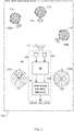
- FIG. 1 is a schematic illustration of a hearing instrument 102, or a hearing instrument system 102 as discussed in further detail below, in accordance with a first embodiment of the present invention operating in an adverse sound or listening environment.
- the hearing instrument 102 is configured to determine an objective perceptual quantity of a received noisy speech signal of the listening environment using directional sound information as discussed in further detail below.
- the hearing instrument 102 may comprise a housing or shell configured for placement at, or in, a hearing impaired individual's left or right ear (not shown).
- the hearing instrument 102 may comprise different types of hearing instruments such as so-called BTE types, ITE types, CIC types, RIC types etc.
- the microphone arrangement of the hearing instrument may be located at various locations at, or in, the user's ear such as behind the user's pinnae, or inside the user's outer ear or inside the user's ear canal.
- the hearing impaired individual (not shown) wishes to receive a target speech signal 110 or possibly other types of sound, produced by a target or desired speaker 112 who is placed some distance away from the hearing impaired individual 102 at or close to the latter's median plane.
- a target speech signal 110 or possibly other types of sound
- the sound environment surrounding the hearing impaired individual may be adverse and the noisy speech signal 111 at the location of a pair of omnidirectional microphones 104, 105 of an adjustable microphone arrangement of the hearing instrument 102 suffer from a low signal-to-noise (SNR).
- SNR signal-to-noise
- the interfering speech signals 109a, 109b generated by the interfering speakers 114, 116 therefore represent noise sources for the hearing aid user in the present listening environment and are likely to lower speech intelligibility of the target speech 110.
- the skilled person will understand that the noise signals 109a, 109b in practice may comprise many other types of common noise sources such as machine noise, wind noise, babble noise, speech and music from television and radio etc. instead of or in addition to interfering speech signals.
- the noise signals may in addition to direct noise sound components from the various noise sources also comprise various boundary reflections from room boundaries 120 of the room, hall or chamber where the hearing impaired individual is placed.
- noisy speech signal 111 is impinging on the pair of omnidirectional microphones 104, 105 and this noisy speech signal 111 comprises a mixture of the desired/target speech signal 110 and interfering speech signals 109a, 109b.
- the hearing instrument 102 comprises an adjustable microphone arrangement 104, 105, directivity index configured for generating one or more microphone signal(s) in response to the incoming sound from the surrounding sound environment or sound field such as the noisy speech signal discussed above.
- the hearing instrument 102 further comprises a hearing aid signal processor (refer to item 240 on FIG. 2 ) configured to executing steps of controlling the adjustable microphone arrangement to produce a first predetermined directivity pattern 107a exhibiting a first directivity index.
- the directivity pattern 107a is schematically illustrated on graph 107 and exhibits a markedly directional nature with a main lobe pointing toward the target speaker 112 placed approximately at 0 degree direction.
- the first predetermined directivity pattern 107a may have been recorded at a relevant or suitable reference frequency within the speech frequency range, e.g. a reference frequency somewhere between 200 Hz and 5 kHz for example at 1 kHz.
- the first directivity index may be larger than 4 dB, or larger than 6 dB, or larger than 10 dB to provide good suppression of interfering noise from other directions than the one where the target speaker is located, e.g. frontal direction.
- the hearing aid signal processor is configured or programmed, for example via a suitable program routine or program thread, to record or store a first noisy speech segment generated by the adjustable microphone arrangement in response to the noisy speech signal 111 using the first predetermined directivity pattern.
- the first noisy speech segment may for example be stored in a suitable data memory area of a volatile or non-volatile memory of the hearing instrument 102 or any other suitable memory buffer.
- the length of the first noisy speech segment will vary depending on the nature of the objective perceptual quantity to be computed.
- the objective perceptual quantity may be a speech intelligibility measure such as a standardized objective intelligibility measure for example a short-time objective intelligibility measure (STOI).
- STOI short-time objective intelligibility measure
- the adjustable microphone arrangement 104, 105, directivity index may comprise first and second analog-to-digital converters (not shown) configured to sample and digitize first and second analog omnidirectional microphone signals supplied by the first and second omnidirectional microphones 104, 105 so as to produce first and second digital microphone signals.
- Each of the first and second digital microphone signals may have a sampling frequency between 6 kHz and 48 kHz and a resolution between 12 and 24 bits.
- the hearing aid signal processor may be configured to produce a directional microphone signal 125 possessing the first predetermined directivity pattern 107a by applying a suitable directional algorithm to the first and second digital microphone signals.
- the first predetermined directivity pattern 107a can be adjusted as desired in a highly flexible manner under the control of the hearing aid signal processor by the directional algorithm.
- the directional algorithm may comprise a delay and subtract function with a variable time delay between the first and second digital microphone signals.
- the adjustable microphone arrangement 104, 105, directivity index may furthermore produce a substantially omnidirectional microphone signal 124 possessing a second predetermined directivity pattern 108a in a simple manner by selecting just one of the first and second digital omnidirectional microphone signals for further processing.
- the directivity index may rely on a combination of an omnidirectional microphone element and a directional microphone element where the latter comprises a traditional pressure gradient microphone having a pair of spaced apart sound ports leading to opposite sides of a common diaphragm.
- the directional microphone signal 125 exhibiting the first predetermined directivity pattern 107a may be produced directly at the output of the directional microphone element while the substantially omnidirectional microphone signal 124 may be recorded directly from the output of the omnidirectional microphone element.
- the hearing aid signal processor can for example switch the adjustable microphone arrangement between the first and second predetermined directivity patterns 107a, 108a by switching between the microphone signals produced at the outputs of the directional and omnidirectional microphone elements.
- the hearing aid signal processor After, or simultaneously with using parallel processing, the hearing aid signal processor records or stores the first noisy speech segment generated by the adjustable microphone arrangement using the first predetermined directivity pattern, the hearing aid signal processor controls the adjustable microphone arrangement to produce the previously discussed second predetermined directivity pattern 108a.
- the first directivity index is larger than the second directivity index at least at the previously discussed one or more reference frequencies or frequency ranges.
- the first directivity index may for example be at least 3 dB or 6 dB larger than the second directivity index at each of the one or more reference frequencies.
- the second directivity index may for example lie between 0 dB and 2 dB to provide nearly omnidirectional sound pick-up.
- the hearing aid signal processor records or stores, in a second address range of the data memory, a second noisy speech segment generated by the adjustable microphone arrangement using the second predetermined directivity pattern.
- the first noisy speech segment and the second noisy speech segment may comprise substantially time-aligned sections of the noisy speech signal 111.
- the first and second omnidirectional digital microphone signals may be temporarily stored in a suitable memory buffer of the hearing aid signal processor before being subjected to the previously discussed beamforming algorithm to form the directional microphone signal possessing the first predetermined directivity pattern 107a.
- a time-aligned omnidirectional microphone signal producing the second noisy speech segment may be formed by selecting one of the stored first and second omnidirectional digital microphone signals from the appropriate buffer location or address.
- the hearing aid signal processor may subsequently retrieve the first noisy speech segment and the second noisy speech segment from the appropriate locations or addresses of the data memory and determine one or more values of the objective perceptual quantity of the noisy speech signal by comparing the first noisy speech segment and the second noisy speech segment. Thereafter, the hearing aid signal processor may flush the first noisy speech segment and the second noisy speech segment from the data memory and start computing a second or following value of the objective perceptual quantity by once again generating and forming a new pair of noisy speech segments from the noisy speech signal and compute the corresponding value of the objective perceptual quantity. In this manner, the hearing aid signal processor may be configured to regularly, e.g.
- a time delay between the start time of the first and second noisy speech segments and the delivery time of the corresponding value of the objective perceptual quantity may lie between 500 ms and 5 s and is preferably smaller than 4 s.
- the hearing aid signal processor may be configured to compute the previously discussed short-time objective intelligibility (STOI) measure which is well-suited to compute accurate intelligibility scores of several types of speech signal degradation often encountered in hearing instruments such as additive noise, reverberation, filtering and clipping.
- STOI short-time objective intelligibility
- the computation of STOI values requires access to both the noisy speech signal and the clean speech signal which means that this otherwise useful objective intelligibility measure has been considered unfit for online or live hearing instrument applications where only the noisy speech signal, as picked-up by the hearing aid microphone, is normally available for analysis.
- the present invention has solved this problem by producing a so-called "pseudo" clean speech signal replacing the unavailable "true” clean speech signal by exploiting spatially directional properties of the microphone arrangement of the hearing instrument.
- a marked suppression of the interfering speech signals 109a, 109b, and other noise sources present within the listening environment, in the first noisy speech segment is achieved by receiving or recording the first speech segment using the first predetermined directivity pattern 107a which may possess a relatively large directivity index, i.e. a narrow beam pattern, pointing towards the target speaker 112.
- this level may be sufficiently small to allow accurate estimation of the STOI values by appropriate selection or setting of the first directivity index as discussed in further detail below with reference to the experimental results obtained by the inventors.
- the hearing instrument 102 may accordingly be adapted to continuously compute STOI values characterizing the intelligibility of the desired/target speech signal 110 at received at the microphone arrangement of the hearing instrument 102.
- STOI values close to 1.0 indicate perfect intelligibility of the desired/target speech signal 110 while STOI values close to 0.0 indicates zero speech intelligibility.
- the skilled person will appreciate that the computed STOI values may be utilized by the hearing aid signal processor in numerous ways to adapt the processing of the hearing loss compensated output signal supplied to the hearing aid user's left or right ear.
- the hearing aid signal processor may for example activate or deactivate certain signal processing algorithms in dependence of current STOI values.
- the hearing aid signal processor may be adapted to adjusting a parameter value or values of the same signal processing algorithms without necessarily deactivating the algorithm.
- the hearing aid signal processor may for example deactivate a single-channel noise reduction algorithm when a current STOI value lies above a predetermined threshold and activate the single-channel noise reduction algorithm when the current STOI value falls below the predetermined threshold.
- the hearing user may benefit from the absence of audible sound artifacts of the hearing loss compensated output signal introduced by the active single-channel noise reduction algorithm in sound environments where the intelligibility of the desired/target speech signal 110 is sufficiently high to allow the hearing aid user to understand incoming speech and communicate without difficulty.
- the hearing aid signal processor may activate the single-channel noise reduction algorithm because the hearing aid user is able to benefit from the resulting noise reduction by improved intelligibility of the desired/target speech signal 110 despite the introduction of certain audible sound artifacts in the hearing loss compensated output signal.
- the hearing aid signal processor may be adapted activate/deactivate numerous other types of signal processing algorithms, or adjusting parameter values of the same, depending on current values of the objective perceptual quantity in question for example a multi-channel dynamic range compression algorithm, a beamforming algorithm or a feedback cancellation algorithm.
- the number of advanced signal processing algorithms applied to the hearing loss compensated output signal may be adapted to track the adverseness of the hearing aid user's listening or sound environment. This tracking may be carried out such that only a minimum amount of signal processing is applied to the target speech signal by the hearing aid signal processor under favorable listening conditions, i.e. those characterized by a low level of interfering speech and/or noise leading to a relatively high STOI value.
- a corresponding effect may of course often be achieved by adjusting certain parameter values of the active signal processing algorithms to increase or decrease the impact that a particular algorithm imparts to the hearing loss compensated output signal instead of deactivating the signal processing algorithms.
- the STOI values determined or computed from the first and second noisy speech segments of the noisy microphone signal are used to control the directivity pattern of the microphone arrangement via an adjustable beamforming algorithm.
- the hearing aid signal processor adapts the adjustable beamforming algorithm to produce a largely omnidirectional directivity pattern for example as the illustrated directivity pattern 108a. This may be achieved by simply disconnecting one of the two omnidirectional microphones 104, 105 or by adjusting a particular parameter such as the intra-microphone time delay or phase difference, of the adjustable beamforming algorithm.
- the hearing aid signal processor adapts the adjustable beamforming algorithm to produce a gradually more directional directivity pattern, i.e.
- the directivity index values may be adjusted to conform to the directivity pattern 107a illustrated on polar plot 107 for STOI values close to 0.1.
- the latter directivity pattern may be a cardioid or hyper cardioid directivity pattern or any other suitable directivity pattern providing good suppression of off-center sound sources where center means sound sources at approximately 0 degree azimuth, or orientation, on the polar plots 107, 108.
- the maximum amount of achievable directivity will, however, also depend on the physical characteristics of the microphone arrangement, in particular the number of individual microphones therein and spacing between individual microphone sound ports.
- the capture of the first and second noisy speech segments of the noisy speech signal via the incoming microphone signal 111 and the subsequent computation of the value or values of the objective perceptual quantity in question of the noisy speech signal, such as the above-discussed STOI values, may be carried out exclusively by the hearing aid signal processor of the hearing instrument 102 in some embodiments of the invention as schematically illustrated above.
- the capture of the first and second noisy speech segments of the noisy speech signal and the various storage and signal processing functions applied to the first and second noisy speech segments, as outlined above may be distributed between two separate portable devices.
- the two separate portable devices form in conjunction a hearing aid apparatus or system carrying out/implementing the present methodology of determining the objective perceptual quantity of the noisy speech signal.
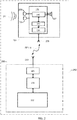
- Such a hearing aid system may, as schematically illustrated in FIG. 2 , comprise a first hearing instrument 201 and a portable terminal 250 connected to each other via a bi-directional wireless data communication link, RF link.
- the portable terminal 250 may comprise a mobile phone, smartphone, tablet, or similar battery powered portable communication terminal.
- Other embodiments of the hearing aid system 202 may comprise a second hearing instrument (not shown) wirelessly connected to the first hearing instrument 201 so as to form a binaural hearing aid system.
- the first hearing instrument or aid 201 of the hearing aid system 202 may be largely identical to the previously discussed hearing instrument 102 except for the addition of a wireless communication interface comprising a wireless receiver or transceiver 234, a communication controller 260 and an RF antenna 236.
- the wireless communication interface allows the first hearing instrument 201 to transmit wireless data, in particular data comprising the previously discussed first and second noisy speech segments, to the portable terminal 250.
- the first and second noisy speech segments may be modulated and transmitted as an analog signal or as a digitally encoded data via the wireless communication link.
- the wireless communication link may be based on RF signal transmission, e.g. FM technology or digital transmission technology for example complying with a Bluetooth standard or other standardized RF communication protocols.
- the wireless communication link may be based on optical signal transmission or near-field magnetic coupling.
- the portable terminal 250 comprises a second wireless transceiver 254 configured to transmit and receive data such as the first and second noisy speech segments through the wireless communication link.
- the portable terminal 250 comprises a signal processor 252 and a data memory 256.
- the signal processor 252 and data memory 256 may be integrated on a single semiconductor die.
- the data memory 256 may comprise different types of memory such as non-volatile EEPROM or volatile RAM memory.
- the signal processor 252 may comprise a software programmable microprocessor such that the below discussed functions are implemented by executable program instructions of one or more program routines executed on the signal processor 252.
- the signal processor 252 is preferably configured to write the first noisy speech segment and the second noisy speech segment to a predetermined memory area or address of the data memory 256.
- the signal processor 252 is preferably further configured to determining the previously discussed STOI value or values, or any other objective perceptual quantity of the noisy speech signal.
- the signal processor 252 may retrieve or read the first noisy speech segment and the second noisy speech segment from data memory 256 and performs the correlation of the first and second noisy speech segments following the standard for intrusive STOI calculation.
- the signal processor 252 thereafter transmits the computed STOI value or values back to the first hearing instrument 201 via the wireless communication link and RF antenna 253.
- the hearing aid signal processor 240 reads the received STOI value or values and may utilize these to perform the previously discussed activation/deactivation of various types of signal processing algorithms or to adjust parameter values of the same.
- FIG. 3 is a simplified schematic illustration of a laboratory measurement set-up for testing the above-discussed methodology of determining the STOI values of the noisy speech signal.
- a test hearing instrument 302 with an adjustable microphone arrangement which instrument may be similar to the previously discussed hearing instrument 102, is mounted on or at a left ear of a suitable head and torso simulator, such as HATS or KEMAR, simulating average acoustic properties of the human head and torso.
- a target or desired speaker 312 is placed some distance away from the KEMAR (simulating the hearing impaired user) at or close to the latter's median plane, i.e. substantially 0 degree azimuth.
- the sound environment surrounding KEMAR and test hearing instrument 302 comprises in addition to the target speaker 312 a first interfering speaker 314 placed at about 140 degrees azimuth and generating a first interfering speech signal 309b and a second interfering speaker 316 is placed at about 270 degrees azimuth and generating a second interfering speech signal 309a.
- the experiment utilizes one embodiment of the present methodology for determining STOI values of the noisy speech signal 311 at the adjustable microphone arrangement of the hearing instrument 302 by relying on the previously discussed "pseudo" clean speech signal obtained through exploitation of spatially directional or selective properties of the adjustable microphone arrangement 302.
- the microphone arrangement is initially adjusted to produce a first predetermined directivity pattern with a relatively high directivity index as discussed before to attenuate or suppress components of the first and second interfering speech signals 309a, 309b to the extent possible.
- the first predetermined directivity pattern is produce by a beamforming module or function 325 in the experimental set-up.
- a "pseudo" clean speech segment is thereafter obtained from the noisy speech signal 311 by the directional properties of the microphone arrangement 302.
- the "pseudo" clean speech segment is recorded via input 322 of the STOI computation unit or device 320.
- the latter may comprise an electrical interface device coupled to a personal computer running a suitable MATLAB program for performing the STOI calculations.
- a near-field microphone 315 is arranged adjacent to the target speaker 312 to simultaneously record a "true" clean target speech signal 310, i.e. a reference signal, and transmits the latter to the STOI computation unit or device 320 via signal line 321.
- the microphone arrangement is adjusted to produce a second predetermined directivity pattern with a relatively small directivity index, for example smaller than 1 dB as discussed before, such that the first and second interfering speech signals 309a, 309b are rendered essentially unattenuated.
- a noisy speech segment is recorded from the noisy speech signal 311 via input 324 of the STOI computation unit or device 320.
- the "true" clean speech segment derived from the target speech signal 310 is correlated with the noisy speech segment derived from the noisy speech signal 311 and the STOI value computed and mapped to graph 400 of FIG. 4 .
- the "pseudo" clean speech segment is likewise correlated with the noisy speech segment and the corresponding STOI value computed and mapped to graph 400 of FIG. 4 .
- the reference curve or plot 403 of graph 400 shows experimentally measured and computed STOI values of the noisy speech signal 311 using the "true” clean speech segment for a broad range of signal-to-noise ratios of the noisy speech signal 311 between -20 dB and + 20 dB.
- the beam-formed signal plot 405 of graph 400 shows the corresponding experimentally measured and computed STOI values of the noisy speech signal 311 using the "pseudo" clean speech segment for correlation instead of the "true” clean speech segment.
- the STOI values approach 1.0 for both test cases when the signal-to-noise ratio of the noisy speech signal 311 is sufficiently high e.g. at or above + 20 dB.
- the plots 423, 425 of the lowermost graph 420 of FIG. 4 shows measured and computed STOI values for the same measurement set-up ( FIG. 3 ) but using a pair of broad-band noise sources as interfering noise sources, or jammers, instead of the pair of speech interferer 309a, 309b used for the plots 403, 405 of graph 400.
Landscapes
- Engineering & Computer Science (AREA)
- Acoustics & Sound (AREA)
- Signal Processing (AREA)
- Health & Medical Sciences (AREA)
- Physics & Mathematics (AREA)
- Otolaryngology (AREA)
- General Health & Medical Sciences (AREA)
- Neurosurgery (AREA)
- Human Computer Interaction (AREA)
- Multimedia (AREA)
- Audiology, Speech & Language Pathology (AREA)
- Computational Linguistics (AREA)
- Quality & Reliability (AREA)
- Circuit For Audible Band Transducer (AREA)
Claims (15)
- Procédé de détermination d'une quantité perceptive objective et intrusive d'un signal vocal bruité (111) en utilisant des informations sonores directionnelles, comprenant les étapes suivantes :a) l'application d'un signal vocal bruité (111) comprenant un mélange de parole cible et de bruit perturbateur à un premier instrument auditif (102), dans lequel ledit premier instrument auditif (102) comprend un agencement de microphone réglable (104, 105),b) la commande de l'agencement de microphone réglable (104, 105) pour produire un premier modèle de directivité prédéterminé (107a) présentant un premier indice de directivité,c) l'enregistrement d'un premier segment vocal bruité généré par l'agencement de microphone réglable (104, 105) en utilisant le premier modèle de directivité prédéterminé,d) la commande de l'agencement de microphone réglable (104, 105) pour produire un deuxième modèle de directivité prédéterminé (108a) présentant un deuxième indice de directivité, dans lequel ledit deuxième indice de directivité est inférieur au premier indice de directivité à une ou plusieurs fréquences de référence,e) l'enregistrement d'un deuxième segment vocal bruité généré par l'agencement de microphone réglable (104, 105) en utilisant le deuxième modèle de directivité prédéterminé (108a),f) la détermination d'au moins une valeur de la quantité perceptive objective et intrusive du signal vocal bruité (111) par un processeur de signal (240) en comparant le premier segment vocal bruité et le deuxième segment vocal bruité.
- Procédé de détermination d'une quantité perceptive objective et intrusive d'un signal vocal bruité (111) selon la revendication 1, dans lequel la quantité perceptive objective comprend une ou plusieurs parmi : une mesure d'intelligibilité de la parole et une mesure de qualité de la parole.
- Procédé de détermination d'une quantité perceptive objective et intrusive d'un signal vocal bruité (111) selon la revendication 2, dans lequel la mesure d'intelligibilité de la parole comprend une mesure d'intelligibilité objective standardisée telle qu'une mesure d'intelligibilité objective de courte période (STOI), une métrique de covariance normalisée (NCM), un indice de transmission vocale (STI), un indice d'articulation (AI), etc.
- Procédé de détermination d'une quantité perceptive objective et intrusive d'un signal vocal bruité (111) selon la revendication 2, dans lequel la mesure de qualité de la parole comprend une mesure de qualité de la parole objective standardisée telle que PESQ, POLQA, etc.
- Procédé de détermination d'une quantité perceptive objective et intrusive d'un signal vocal bruité (111) selon l'une quelconque des revendications 1 à 4, comprenant en outre les étapes suivantes :h) l'activation ou la désactivation d'au moins un algorithme de traitement de signal exécuté sur un processeur de signal de prothèse auditive (240) sur la base de l'au moins une valeur de la quantité perceptive objective ; et/ou
le réglage d'une valeur de paramètre de l'au moins un algorithme de traitement de signal sur la base de l'au moins une valeur de la quantité perceptive objective et intrusive,g) le traitement d'un signal de microphone généré par l'agencement de microphone (104, 105) conformément à un algorithme de traitement de signal actif et/ou à la valeur de paramètre réglée pour produire un premier signal de sortie compensé en perte auditive de l'instrument auditif (201),i) la reproduction du premier signal de sortie compensé en perte auditive sur l'oreille gauche ou droite de l'utilisateur par le biais d'un premier transducteur de sortie (32). - Procédé de détermination d'une quantité perceptive objective d'un signal vocal bruité (111) selon la revendication 5, comprenant une autre étape suivante :le réglage progressif de la valeur de paramètre de l'au moins un algorithme de traitement de signal conformément à des valeurs de la quantité perceptive objective et intrusive.
- Procédé de détermination d'une quantité perceptive objective et intrusive d'un signal vocal bruité (111) selon la revendication 5 ou 6, dans lequel l'au moins un algorithme de traitement de signal comprend un parmi : un algorithme de formation de faisceau réglable, un algorithme d'annulation de retour adaptative, un algorithme de réduction de bruit de canal individuel, un algorithme de réduction de bruit multi-canal, un algorithme de compression de plage dynamique multi-canal.
- Procédé de détermination d'une quantité perceptive objective et intrusive d'un signal vocal bruité (111) selon l'une quelconque des revendications précédentes, comprenant en outre les étapes suivantes :- la transmission du premier segment vocal bruité et du deuxième segment vocal bruité de l'instrument auditif (201) à un terminal fixe, un terminal portable ou un deuxième instrument auditif (250) par le biais d'une liaison de communication sans fil,- l'enregistrement du premier segment vocal bruité et du deuxième segment vocal bruité dans une zone de mémoire de données (256) du terminal fixe, du terminal portable ou du deuxième instrument auditif (250),- la détermination de l'au moins une valeur de la qualité perceptive objective du signal vocal bruité par un processeur de signal du terminal fixe, du terminal portable ou du deuxième instrument auditif (250),- la transmission de l'au moins une valeur de la qualité perceptive objective du terminal fixe, du terminal portable ou du deuxième instrument auditif au premier instrument auditif (201) par le biais de la liaison de communication sans fil.
- Procédé de détermination d'une quantité perceptive objective et intrusive d'un signal vocal bruité (111) selon l'une quelconque des revendications 1 à 8, comprenant en outre les étapes suivantes :- l'enregistrement du premier segment vocal bruité et du deuxième segment vocal bruité dans une mémoire de données du premier instrument auditif (201),- la détermination de la valeur de l'au moins une valeur de la qualité perceptive objective du signal vocal bruité (111) par un processeur de signal (240) du premier instrument auditif (201).
- Procédé de détermination d'une quantité perceptive objective et intrusive d'un signal vocal bruité selon l'une quelconque des revendications précédentes, dans lequel :le deuxième indice de directivité est inférieur à 2 dB à une fréquence de référence de 1 kHz ; etle premier indice de directivité est supérieur à 4 dB, de préférence supérieur à 5 dB, ou supérieur à 6 dB, à la fréquence de référence de 1 kHz.
- Procédé de détermination d'une quantité perceptive objective et intrusive d'un signal vocal bruité (111) selon l'une quelconque des revendications précédentes, dans lequel :le deuxième indice de directivité est inférieur à 2 dB entre 500 Hz et 3 kHz ; etle premier indice de directivité est supérieur à 4 dB, de préférence supérieur à 5 dB, ou supérieur à 6 dB, entre 500 Hz et 3 kHz.
- Procédé de détermination d'une quantité perceptive objective et intrusive d'un signal vocal bruité (111) selon l'une quelconque des revendications précédentes, dans lequel :le deuxième indice de directivité est inférieur au premier indice de directivité sur toute une plage de fréquences vocales prédéterminée telle qu'entre 200 Hz et 5 kHz ou entre 500 Hz et 3 kHz.
- Instrument auditif (201) comprenant :- un boîtier ou une enveloppe de prothèse auditive configuré pour la mise en place au niveau ou dans une oreille gauche ou droite d'un utilisateur,- un agencement de microphone réglable (104, 105) configuré pour générer un signal de microphone en réponse à un son en entrée provenant d'un champ sonore entourant l'instrument auditif (201), où ledit son en entrée comprend un signal vocal bruité (111) ayant un mélange de parole cible et de bruit perturbateur,- un processeur de signal de prothèse auditive (240) configuré pour exécuter les étapes suivantes :- la commande de l'agencement de microphone réglable (104, 105) pour produire un premier modèle de directivité prédéterminé (107a) présentant un premier indice de directivité,- l'enregistrement, dans une première zone d'adresse d'une mémoire de données, d'un premier segment vocal bruité généré par l'agencement de microphone réglable (104, 105) en utilisant le premier modèle de directivité prédéterminé,- la commande de l'agencement de microphone réglable (104, 105) pour produire un deuxième modèle de directivité prédéterminé (108a) présentant un deuxième indice de directivité, dans lequel ledit deuxième indice de directivité est inférieur au premier indice de directivité à une ou plusieurs fréquences de référence,e) l'enregistrement, dans une deuxième zone d'adresse de la mémoire de données, d'un deuxième segment vocal bruité généré par l'agencement de microphone réglable (104, 105) en utilisant le deuxième modèle de directivité prédéterminé ,f) la détermination de l'au moins une valeur d'une quantité perceptive objective et intrusive du signal vocal bruité en comparant le premier segment vocal bruité et le deuxième segment vocal bruité.
- Instrument auditif selon la revendication 13, dans lequel l'agencement de microphone réglable (104, 105) comprend au moins :un premier microphone omnidirectionnel et un deuxième microphone omnidirectionnel, ou un microphone omnidirectionnel et un microphone directionnel.
- Système d'aide auditive comprenant un premier instrument auditif (201) et un parmi un terminal fixe, un terminal portable et un deuxième instrument auditif (250), le premier instrument auditif (201) comprenant :un boîtier ou une enveloppe de prothèse auditive configuré pour la mise en place au niveau ou dans une oreille gauche ou droite d'un utilisateur,un agencement de microphone réglable (104, 105) configuré pour générer un signal de microphone en réponse à un son en entrée provenant d'un champ sonore entourant le premier instrument auditif (201), où ledit son en entrée comprend un signal vocal bruité (111) ayant un mélange de parole cible et de bruit perturbateur,un processeur de signal de prothèse auditive (240) configuré pour exécuter les étapes suivantes :- la commande de l'agencement de microphone réglable (104, 105) pour produire un premier modèle de directivité prédéterminé (107a) présentant un premier indice de directivité,- la réception d'un premier segment vocal bruité généré par l'agencement de microphone réglable (104, 105) en utilisant le premier modèle de directivité prédéterminé (107a),- la commande de l'agencement de microphone réglable (104, 105) pour produire un deuxième modèle de directivité prédéterminé (108a) présentant un deuxième indice de directivité, dans lequel ledit deuxième indice de directivité est l'inférieur au premier indice de directivité à une ou plusieurs fréquences de référence,- la réception d'un deuxième segment vocal bruité généré par l'agencement de microphone réglable (104, 105) en utilisant le deuxième modèle de directivité prédéterminé (107a),un premier émetteur sans fil (234) configuré pour transmettre le premier segment vocal bruité et le deuxième segment vocal bruité au terminal portable ou au deuxième instrument auditif (250) par le biais d'une liaison de communication sans fil ;le terminal fixe, le terminal portable ou le deuxième instrument auditif (250) comprenant :un deuxième émetteur-récepteur sans fil (254) configuré pour transmettre et recevoir des données par le biais de la liaison de communication sans fil,un processeur de signal configuré pour :- enregistrer le premier segment vocal bruité et le deuxième segment vocal bruité dans une zone de mémoire de données du terminal portable ou dans une zone de mémoire de données du deuxième instrument auditif,- déterminer au moins une valeur d'une qualité perceptive objective et intrusive du signal vocal bruité en comparant le premier segment vocal bruité et le deuxième segment vocal bruité,- transmettre l'au moins une valeur de la qualité perceptive objective et intrusive du terminal fixe, du terminal portable ou du deuxième instrument auditif (250) au premier instrument auditif (201) par le biais de la liaison de communication sans fil.
Applications Claiming Priority (1)
| Application Number | Priority Date | Filing Date | Title |
|---|---|---|---|
| DKPA201570608 | 2015-09-24 |
Publications (2)
| Publication Number | Publication Date |
|---|---|
| EP3147904A1 EP3147904A1 (fr) | 2017-03-29 |
| EP3147904B1 true EP3147904B1 (fr) | 2018-04-25 |
Family
ID=56893833
Family Applications (1)
| Application Number | Title | Priority Date | Filing Date |
|---|---|---|---|
| EP16187961.4A Active EP3147904B1 (fr) | 2015-09-24 | 2016-09-09 | Procédé de détermination de quantités perceptives objectives de signaux de parole bruités |
Country Status (5)
| Country | Link |
|---|---|
| US (1) | US10397711B2 (fr) |
| EP (1) | EP3147904B1 (fr) |
| JP (1) | JP6905319B2 (fr) |
| CN (1) | CN106878905B (fr) |
| DK (1) | DK3147904T3 (fr) |
Families Citing this family (12)
| Publication number | Priority date | Publication date | Assignee | Title |
|---|---|---|---|---|
| US9723415B2 (en) * | 2015-06-19 | 2017-08-01 | Gn Hearing A/S | Performance based in situ optimization of hearing aids |
| US10206040B2 (en) * | 2015-10-30 | 2019-02-12 | Essential Products, Inc. | Microphone array for generating virtual sound field |
| US10490206B2 (en) * | 2016-01-19 | 2019-11-26 | Dolby Laboratories Licensing Corporation | Testing device capture performance for multiple speakers |
| CN107221339B (zh) * | 2017-05-22 | 2020-08-14 | 华北电力大学 | 基于增益补偿助听器语音质量w-pesq客观评价方法 |
| EP3671739A1 (fr) * | 2018-12-21 | 2020-06-24 | FRAUNHOFER-GESELLSCHAFT zur Förderung der angewandten Forschung e.V. | Appareil et procédé de séparation de source à l'aide d'une estimation et du contrôle de la qualité sonore |
| CN110120217B (zh) * | 2019-05-10 | 2023-11-24 | 腾讯科技(深圳)有限公司 | 一种音频数据处理方法及装置 |
| CN110517708B (zh) * | 2019-09-02 | 2024-06-07 | 平安科技(深圳)有限公司 | 一种音频处理方法、装置及计算机存储介质 |
| CN110853664B (zh) * | 2019-11-22 | 2022-05-06 | 北京小米移动软件有限公司 | 评估语音增强算法性能的方法及装置、电子设备 |
| DE102020207579A1 (de) * | 2020-06-18 | 2021-12-23 | Sivantos Pte. Ltd. | Verfahren zur richtungsabhängigen Rauschunterdrückung für ein Hörsystem, welches eine Hörvorrichtung umfasst |
| CN114187895B (zh) * | 2021-12-17 | 2024-09-24 | 海尔优家智能科技(北京)有限公司 | 语音识别方法、装置、设备和存储介质 |
| US12452610B2 (en) * | 2021-12-30 | 2025-10-21 | Fuliang Wang | Methods for synthesis-based clear hearing under noisy conditions |
| CN119495320B (zh) * | 2024-11-21 | 2025-06-03 | 广州恒丰智能机电设备有限公司 | 噪音检测设备控制方法和系统 |
Family Cites Families (22)
| Publication number | Priority date | Publication date | Assignee | Title |
|---|---|---|---|---|
| US5878147A (en) | 1996-12-31 | 1999-03-02 | Etymotic Research, Inc. | Directional microphone assembly |
| WO2001095666A2 (fr) * | 2000-06-05 | 2001-12-13 | Nanyang Technological University | Systeme de microphone antibruit directionnel adaptatif |
| US6704422B1 (en) | 2000-10-26 | 2004-03-09 | Widex A/S | Method for controlling the directionality of the sound receiving characteristic of a hearing aid a hearing aid for carrying out the method |
| US7260236B2 (en) * | 2001-01-12 | 2007-08-21 | Sonionmicrotronic Nederland B.V. | Wind noise suppression in directional microphones |
| US6556729B2 (en) * | 2001-07-27 | 2003-04-29 | The United States Of America As Represented By The National Security Agency | Acousto-optic bandpass filter |
| US7369669B2 (en) * | 2002-05-15 | 2008-05-06 | Micro Ear Technology, Inc. | Diotic presentation of second-order gradient directional hearing aid signals |
| DE602005006536D1 (de) | 2004-03-01 | 2008-06-19 | Gn Resound As | Hörgerät mit automatischer umschaltung zwischen betriebsarten |
| US8396224B2 (en) * | 2006-03-03 | 2013-03-12 | Gn Resound A/S | Methods and apparatuses for setting a hearing aid to an omnidirectional microphone mode or a directional microphone mode |
| WO2009022278A1 (fr) * | 2007-08-14 | 2009-02-19 | Koninklijke Philips Electronics N.V. | Système de reproduction audio comprenant des haut-parleurs à directivité étroite et large |
| CN101466055A (zh) * | 2008-12-31 | 2009-06-24 | 瑞声声学科技(常州)有限公司 | 小型麦克风阵列装置及其波束形成方法 |
| JP5293275B2 (ja) * | 2009-03-03 | 2013-09-18 | 船井電機株式会社 | マイクロホンユニット |
| EP2339574B1 (fr) * | 2009-11-20 | 2013-03-13 | Nxp B.V. | Détecteur de voix |
| WO2011105003A1 (fr) * | 2010-02-25 | 2011-09-01 | パナソニック株式会社 | Appareil de traitement de signal et procédé de traitement de signal |
| EP2596647B1 (fr) * | 2010-07-23 | 2016-01-06 | Sonova AG | Système auditif et procédé d'exploitation d'un système auditif |
| CN103155036B (zh) * | 2010-09-28 | 2015-01-14 | 松下电器产业株式会社 | 语音处理装置及语音处理方法 |
| EP2448289A1 (fr) * | 2010-10-28 | 2012-05-02 | Fraunhofer-Gesellschaft zur Förderung der angewandten Forschung e.V. | Appareil et procédé de dérivation dýinformations directionnelles et systèmes |
| EP2820863B1 (fr) | 2011-12-22 | 2016-06-08 | Widex A/S | Dispositif de prothésé auditive et procédé de fonctionnement correspondant |
| WO2013138747A1 (fr) | 2012-03-16 | 2013-09-19 | Yale University | Système et procédé pour détection et extraction d'anomalie |
| DE102013108011A1 (de) * | 2012-07-27 | 2014-02-13 | Johnson Electric S.A. | Sicherheitshülle |
| US20140270287A1 (en) | 2013-03-15 | 2014-09-18 | Qualcomm Incorporated | Bluetooth hearing aids enabled during voice activity on a mobile phone |
| US9426589B2 (en) * | 2013-07-04 | 2016-08-23 | Gn Resound A/S | Determination of individual HRTFs |
| JP6596924B2 (ja) * | 2014-05-29 | 2019-10-30 | 日本電気株式会社 | 音声データ処理装置、音声データ処理方法、及び、音声データ処理プログラム |
-
2016
- 2016-09-06 US US15/257,762 patent/US10397711B2/en active Active
- 2016-09-09 DK DK16187961.4T patent/DK3147904T3/en active
- 2016-09-09 EP EP16187961.4A patent/EP3147904B1/fr active Active
- 2016-09-21 JP JP2016184447A patent/JP6905319B2/ja active Active
- 2016-09-23 CN CN201610846577.3A patent/CN106878905B/zh active Active
Non-Patent Citations (1)
| Title |
|---|
| None * |
Also Published As
| Publication number | Publication date |
|---|---|
| CN106878905A (zh) | 2017-06-20 |
| JP2017063419A (ja) | 2017-03-30 |
| JP6905319B2 (ja) | 2021-07-21 |
| US10397711B2 (en) | 2019-08-27 |
| US20170094420A1 (en) | 2017-03-30 |
| EP3147904A1 (fr) | 2017-03-29 |
| CN106878905B (zh) | 2021-02-19 |
| DK3147904T3 (en) | 2018-07-23 |
Similar Documents
| Publication | Publication Date | Title |
|---|---|---|
| EP3147904B1 (fr) | Procédé de détermination de quantités perceptives objectives de signaux de parole bruités | |
| US10431239B2 (en) | Hearing system | |
| US10567889B2 (en) | Binaural hearing system and method | |
| US9591411B2 (en) | Self-calibration of multi-microphone noise reduction system for hearing assistance devices using an auxiliary device | |
| EP3373602A1 (fr) | Procédé permettant de localiser une source sonore, dispositif auditif et système auditif | |
| US10327078B2 (en) | Hearing aid comprising a directional microphone system | |
| EP2928214A1 (fr) | Système d'assistance auditive biauriculaire comprenant une réduction de bruit biauriculaire | |
| CN107371111B (zh) | 用于预测有噪声和/或增强的语音的可懂度的方法及双耳听力系统 | |
| EP2947898A1 (fr) | Dispositif auditif | |
| EP2819437A1 (fr) | Procédé et appareil de localisation de sources de diffusion en continu dans un système d'assistance auditive | |
| JP2018113681A (ja) | 適応型の両耳用聴覚指向を有する聴覚機器及び関連する方法 | |
| EP4094685B1 (fr) | Unité d'essai de détection de modulation spectro-temporale |
Legal Events
| Date | Code | Title | Description |
|---|---|---|---|
| PUAI | Public reference made under article 153(3) epc to a published international application that has entered the european phase |
Free format text: ORIGINAL CODE: 0009012 |
|
| AK | Designated contracting states |
Kind code of ref document: A1 Designated state(s): AL AT BE BG CH CY CZ DE DK EE ES FI FR GB GR HR HU IE IS IT LI LT LU LV MC MK MT NL NO PL PT RO RS SE SI SK SM TR |
|
| AX | Request for extension of the european patent |
Extension state: BA ME |
|
| GRAP | Despatch of communication of intention to grant a patent |
Free format text: ORIGINAL CODE: EPIDOSNIGR1 |
|
| 17P | Request for examination filed |
Effective date: 20170927 |
|
| RBV | Designated contracting states (corrected) |
Designated state(s): AL AT BE BG CH CY CZ DE DK EE ES FI FR GB GR HR HU IE IS IT LI LT LU LV MC MK MT NL NO PL PT RO RS SE SI SK SM TR |
|
| INTG | Intention to grant announced |
Effective date: 20171108 |
|
| RAP1 | Party data changed (applicant data changed or rights of an application transferred) |
Owner name: GN HEARING A/S |
|
| GRAS | Grant fee paid |
Free format text: ORIGINAL CODE: EPIDOSNIGR3 |
|
| GRAA | (expected) grant |
Free format text: ORIGINAL CODE: 0009210 |
|
| AK | Designated contracting states |
Kind code of ref document: B1 Designated state(s): AL AT BE BG CH CY CZ DE DK EE ES FI FR GB GR HR HU IE IS IT LI LT LU LV MC MK MT NL NO PL PT RO RS SE SI SK SM TR |
|
| REG | Reference to a national code |
Ref country code: GB Ref legal event code: FG4D |
|
| REG | Reference to a national code |
Ref country code: CH Ref legal event code: EP |
|
| REG | Reference to a national code |
Ref country code: AT Ref legal event code: REF Ref document number: 993701 Country of ref document: AT Kind code of ref document: T Effective date: 20180515 |
|
| REG | Reference to a national code |
Ref country code: IE Ref legal event code: FG4D |
|
| REG | Reference to a national code |
Ref country code: DE Ref legal event code: R096 Ref document number: 602016002645 Country of ref document: DE |
|
| REG | Reference to a national code |
Ref country code: DK Ref legal event code: T3 Effective date: 20180716 |
|
| REG | Reference to a national code |
Ref country code: NL Ref legal event code: MP Effective date: 20180425 |
|
| REG | Reference to a national code |
Ref country code: LT Ref legal event code: MG4D |
|
| REG | Reference to a national code |
Ref country code: FR Ref legal event code: PLFP Year of fee payment: 3 |
|
| PG25 | Lapsed in a contracting state [announced via postgrant information from national office to epo] |
Ref country code: NL Free format text: LAPSE BECAUSE OF FAILURE TO SUBMIT A TRANSLATION OF THE DESCRIPTION OR TO PAY THE FEE WITHIN THE PRESCRIBED TIME-LIMIT Effective date: 20180425 |
|
| PG25 | Lapsed in a contracting state [announced via postgrant information from national office to epo] |
Ref country code: ES Free format text: LAPSE BECAUSE OF FAILURE TO SUBMIT A TRANSLATION OF THE DESCRIPTION OR TO PAY THE FEE WITHIN THE PRESCRIBED TIME-LIMIT Effective date: 20180425 Ref country code: SE Free format text: LAPSE BECAUSE OF FAILURE TO SUBMIT A TRANSLATION OF THE DESCRIPTION OR TO PAY THE FEE WITHIN THE PRESCRIBED TIME-LIMIT Effective date: 20180425 Ref country code: BG Free format text: LAPSE BECAUSE OF FAILURE TO SUBMIT A TRANSLATION OF THE DESCRIPTION OR TO PAY THE FEE WITHIN THE PRESCRIBED TIME-LIMIT Effective date: 20180725 Ref country code: FI Free format text: LAPSE BECAUSE OF FAILURE TO SUBMIT A TRANSLATION OF THE DESCRIPTION OR TO PAY THE FEE WITHIN THE PRESCRIBED TIME-LIMIT Effective date: 20180425 Ref country code: NO Free format text: LAPSE BECAUSE OF FAILURE TO SUBMIT A TRANSLATION OF THE DESCRIPTION OR TO PAY THE FEE WITHIN THE PRESCRIBED TIME-LIMIT Effective date: 20180725 Ref country code: PL Free format text: LAPSE BECAUSE OF FAILURE TO SUBMIT A TRANSLATION OF THE DESCRIPTION OR TO PAY THE FEE WITHIN THE PRESCRIBED TIME-LIMIT Effective date: 20180425 Ref country code: LT Free format text: LAPSE BECAUSE OF FAILURE TO SUBMIT A TRANSLATION OF THE DESCRIPTION OR TO PAY THE FEE WITHIN THE PRESCRIBED TIME-LIMIT Effective date: 20180425 |
|
| PG25 | Lapsed in a contracting state [announced via postgrant information from national office to epo] |
Ref country code: GR Free format text: LAPSE BECAUSE OF FAILURE TO SUBMIT A TRANSLATION OF THE DESCRIPTION OR TO PAY THE FEE WITHIN THE PRESCRIBED TIME-LIMIT Effective date: 20180726 Ref country code: HR Free format text: LAPSE BECAUSE OF FAILURE TO SUBMIT A TRANSLATION OF THE DESCRIPTION OR TO PAY THE FEE WITHIN THE PRESCRIBED TIME-LIMIT Effective date: 20180425 Ref country code: LV Free format text: LAPSE BECAUSE OF FAILURE TO SUBMIT A TRANSLATION OF THE DESCRIPTION OR TO PAY THE FEE WITHIN THE PRESCRIBED TIME-LIMIT Effective date: 20180425 Ref country code: RS Free format text: LAPSE BECAUSE OF FAILURE TO SUBMIT A TRANSLATION OF THE DESCRIPTION OR TO PAY THE FEE WITHIN THE PRESCRIBED TIME-LIMIT Effective date: 20180425 |
|
| REG | Reference to a national code |
Ref country code: AT Ref legal event code: MK05 Ref document number: 993701 Country of ref document: AT Kind code of ref document: T Effective date: 20180425 |
|
| PG25 | Lapsed in a contracting state [announced via postgrant information from national office to epo] |
Ref country code: PT Free format text: LAPSE BECAUSE OF FAILURE TO SUBMIT A TRANSLATION OF THE DESCRIPTION OR TO PAY THE FEE WITHIN THE PRESCRIBED TIME-LIMIT Effective date: 20180827 |
|
| REG | Reference to a national code |
Ref country code: DE Ref legal event code: R097 Ref document number: 602016002645 Country of ref document: DE |
|
| PG25 | Lapsed in a contracting state [announced via postgrant information from national office to epo] |
Ref country code: RO Free format text: LAPSE BECAUSE OF FAILURE TO SUBMIT A TRANSLATION OF THE DESCRIPTION OR TO PAY THE FEE WITHIN THE PRESCRIBED TIME-LIMIT Effective date: 20180425 Ref country code: CZ Free format text: LAPSE BECAUSE OF FAILURE TO SUBMIT A TRANSLATION OF THE DESCRIPTION OR TO PAY THE FEE WITHIN THE PRESCRIBED TIME-LIMIT Effective date: 20180425 Ref country code: EE Free format text: LAPSE BECAUSE OF FAILURE TO SUBMIT A TRANSLATION OF THE DESCRIPTION OR TO PAY THE FEE WITHIN THE PRESCRIBED TIME-LIMIT Effective date: 20180425 Ref country code: AT Free format text: LAPSE BECAUSE OF FAILURE TO SUBMIT A TRANSLATION OF THE DESCRIPTION OR TO PAY THE FEE WITHIN THE PRESCRIBED TIME-LIMIT Effective date: 20180425 Ref country code: SK Free format text: LAPSE BECAUSE OF FAILURE TO SUBMIT A TRANSLATION OF THE DESCRIPTION OR TO PAY THE FEE WITHIN THE PRESCRIBED TIME-LIMIT Effective date: 20180425 |
|
| PG25 | Lapsed in a contracting state [announced via postgrant information from national office to epo] |
Ref country code: IT Free format text: LAPSE BECAUSE OF FAILURE TO SUBMIT A TRANSLATION OF THE DESCRIPTION OR TO PAY THE FEE WITHIN THE PRESCRIBED TIME-LIMIT Effective date: 20180425 Ref country code: SM Free format text: LAPSE BECAUSE OF FAILURE TO SUBMIT A TRANSLATION OF THE DESCRIPTION OR TO PAY THE FEE WITHIN THE PRESCRIBED TIME-LIMIT Effective date: 20180425 |
|
| PLBE | No opposition filed within time limit |
Free format text: ORIGINAL CODE: 0009261 |
|
| STAA | Information on the status of an ep patent application or granted ep patent |
Free format text: STATUS: NO OPPOSITION FILED WITHIN TIME LIMIT |
|
| 26N | No opposition filed |
Effective date: 20190128 |
|
| PG25 | Lapsed in a contracting state [announced via postgrant information from national office to epo] |
Ref country code: MC Free format text: LAPSE BECAUSE OF FAILURE TO SUBMIT A TRANSLATION OF THE DESCRIPTION OR TO PAY THE FEE WITHIN THE PRESCRIBED TIME-LIMIT Effective date: 20180425 |
|
| PG25 | Lapsed in a contracting state [announced via postgrant information from national office to epo] |
Ref country code: SI Free format text: LAPSE BECAUSE OF FAILURE TO SUBMIT A TRANSLATION OF THE DESCRIPTION OR TO PAY THE FEE WITHIN THE PRESCRIBED TIME-LIMIT Effective date: 20180425 |
|
| REG | Reference to a national code |
Ref country code: BE Ref legal event code: MM Effective date: 20180930 |
|
| REG | Reference to a national code |
Ref country code: IE Ref legal event code: MM4A |
|
| PG25 | Lapsed in a contracting state [announced via postgrant information from national office to epo] |
Ref country code: LU Free format text: LAPSE BECAUSE OF NON-PAYMENT OF DUE FEES Effective date: 20180909 |
|
| PG25 | Lapsed in a contracting state [announced via postgrant information from national office to epo] |
Ref country code: IE Free format text: LAPSE BECAUSE OF NON-PAYMENT OF DUE FEES Effective date: 20180909 |
|
| PG25 | Lapsed in a contracting state [announced via postgrant information from national office to epo] |
Ref country code: BE Free format text: LAPSE BECAUSE OF NON-PAYMENT OF DUE FEES Effective date: 20180930 |
|
| PG25 | Lapsed in a contracting state [announced via postgrant information from national office to epo] |
Ref country code: AL Free format text: LAPSE BECAUSE OF FAILURE TO SUBMIT A TRANSLATION OF THE DESCRIPTION OR TO PAY THE FEE WITHIN THE PRESCRIBED TIME-LIMIT Effective date: 20180425 |
|
| PG25 | Lapsed in a contracting state [announced via postgrant information from national office to epo] |
Ref country code: MT Free format text: LAPSE BECAUSE OF NON-PAYMENT OF DUE FEES Effective date: 20180909 |
|
| PG25 | Lapsed in a contracting state [announced via postgrant information from national office to epo] |
Ref country code: TR Free format text: LAPSE BECAUSE OF FAILURE TO SUBMIT A TRANSLATION OF THE DESCRIPTION OR TO PAY THE FEE WITHIN THE PRESCRIBED TIME-LIMIT Effective date: 20180425 |
|
| PG25 | Lapsed in a contracting state [announced via postgrant information from national office to epo] |
Ref country code: CY Free format text: LAPSE BECAUSE OF FAILURE TO SUBMIT A TRANSLATION OF THE DESCRIPTION OR TO PAY THE FEE WITHIN THE PRESCRIBED TIME-LIMIT Effective date: 20180425 Ref country code: MK Free format text: LAPSE BECAUSE OF NON-PAYMENT OF DUE FEES Effective date: 20180425 Ref country code: HU Free format text: LAPSE BECAUSE OF FAILURE TO SUBMIT A TRANSLATION OF THE DESCRIPTION OR TO PAY THE FEE WITHIN THE PRESCRIBED TIME-LIMIT; INVALID AB INITIO Effective date: 20160909 |
|
| PG25 | Lapsed in a contracting state [announced via postgrant information from national office to epo] |
Ref country code: IS Free format text: LAPSE BECAUSE OF FAILURE TO SUBMIT A TRANSLATION OF THE DESCRIPTION OR TO PAY THE FEE WITHIN THE PRESCRIBED TIME-LIMIT Effective date: 20180825 |
|
| PGFP | Annual fee paid to national office [announced via postgrant information from national office to epo] |
Ref country code: FR Payment date: 20210914 Year of fee payment: 6 Ref country code: CH Payment date: 20210917 Year of fee payment: 6 |
|
| PGFP | Annual fee paid to national office [announced via postgrant information from national office to epo] |
Ref country code: DK Payment date: 20210916 Year of fee payment: 6 Ref country code: GB Payment date: 20210917 Year of fee payment: 6 |
|
| REG | Reference to a national code |
Ref country code: CH Ref legal event code: PL |
|
| REG | Reference to a national code |
Ref country code: DK Ref legal event code: EBP Effective date: 20220930 |
|
| GBPC | Gb: european patent ceased through non-payment of renewal fee |
Effective date: 20220909 |
|
| P01 | Opt-out of the competence of the unified patent court (upc) registered |
Effective date: 20230526 |
|
| PG25 | Lapsed in a contracting state [announced via postgrant information from national office to epo] |
Ref country code: LI Free format text: LAPSE BECAUSE OF NON-PAYMENT OF DUE FEES Effective date: 20220930 Ref country code: FR Free format text: LAPSE BECAUSE OF NON-PAYMENT OF DUE FEES Effective date: 20220930 Ref country code: CH Free format text: LAPSE BECAUSE OF NON-PAYMENT OF DUE FEES Effective date: 20220930 |
|
| PG25 | Lapsed in a contracting state [announced via postgrant information from national office to epo] |
Ref country code: GB Free format text: LAPSE BECAUSE OF NON-PAYMENT OF DUE FEES Effective date: 20220909 Ref country code: DK Free format text: LAPSE BECAUSE OF NON-PAYMENT OF DUE FEES Effective date: 20220930 |
|
| PGFP | Annual fee paid to national office [announced via postgrant information from national office to epo] |
Ref country code: DE Payment date: 20250917 Year of fee payment: 10 |