EP3147975B1 - Matière d'électrode positive, batterie rechargeable, procédé de fabrication de matière d'électrode positive, et procédé de fabrication de batterie rechargeable - Google Patents
Matière d'électrode positive, batterie rechargeable, procédé de fabrication de matière d'électrode positive, et procédé de fabrication de batterie rechargeable Download PDFInfo
- Publication number
- EP3147975B1 EP3147975B1 EP15795693.9A EP15795693A EP3147975B1 EP 3147975 B1 EP3147975 B1 EP 3147975B1 EP 15795693 A EP15795693 A EP 15795693A EP 3147975 B1 EP3147975 B1 EP 3147975B1
- Authority
- EP
- European Patent Office
- Prior art keywords
- vanadium phosphate
- lithium
- lithium vanadium
- aluminum
- cathode material
- Prior art date
- Legal status (The legal status is an assumption and is not a legal conclusion. Google has not performed a legal analysis and makes no representation as to the accuracy of the status listed.)
- Active
Links
Images














Classifications
-
- H—ELECTRICITY
- H01—ELECTRIC ELEMENTS
- H01M—PROCESSES OR MEANS, e.g. BATTERIES, FOR THE DIRECT CONVERSION OF CHEMICAL ENERGY INTO ELECTRICAL ENERGY
- H01M4/00—Electrodes
- H01M4/02—Electrodes composed of, or comprising, active material
- H01M4/36—Selection of substances as active materials, active masses, active liquids
-
- H—ELECTRICITY
- H01—ELECTRIC ELEMENTS
- H01M—PROCESSES OR MEANS, e.g. BATTERIES, FOR THE DIRECT CONVERSION OF CHEMICAL ENERGY INTO ELECTRICAL ENERGY
- H01M4/00—Electrodes
- H01M4/02—Electrodes composed of, or comprising, active material
- H01M4/36—Selection of substances as active materials, active masses, active liquids
- H01M4/362—Composites
- H01M4/366—Composites as layered products
-
- H—ELECTRICITY
- H01—ELECTRIC ELEMENTS
- H01M—PROCESSES OR MEANS, e.g. BATTERIES, FOR THE DIRECT CONVERSION OF CHEMICAL ENERGY INTO ELECTRICAL ENERGY
- H01M4/00—Electrodes
- H01M4/02—Electrodes composed of, or comprising, active material
- H01M4/36—Selection of substances as active materials, active masses, active liquids
- H01M4/58—Selection of substances as active materials, active masses, active liquids of inorganic compounds other than oxides or hydroxides, e.g. sulfides, selenides, tellurides, halogenides or LiCoFy; of polyanionic structures, e.g. phosphates, silicates or borates
-
- H—ELECTRICITY
- H01—ELECTRIC ELEMENTS
- H01M—PROCESSES OR MEANS, e.g. BATTERIES, FOR THE DIRECT CONVERSION OF CHEMICAL ENERGY INTO ELECTRICAL ENERGY
- H01M4/00—Electrodes
- H01M4/02—Electrodes composed of, or comprising, active material
- H01M4/36—Selection of substances as active materials, active masses, active liquids
- H01M4/58—Selection of substances as active materials, active masses, active liquids of inorganic compounds other than oxides or hydroxides, e.g. sulfides, selenides, tellurides, halogenides or LiCoFy; of polyanionic structures, e.g. phosphates, silicates or borates
- H01M4/5825—Oxygenated metallic salts or polyanionic structures, e.g. borates, phosphates, silicates, olivines
-
- H—ELECTRICITY
- H01—ELECTRIC ELEMENTS
- H01M—PROCESSES OR MEANS, e.g. BATTERIES, FOR THE DIRECT CONVERSION OF CHEMICAL ENERGY INTO ELECTRICAL ENERGY
- H01M4/00—Electrodes
- H01M4/02—Electrodes composed of, or comprising, active material
- H01M4/62—Selection of inactive substances as ingredients for active masses, e.g. binders, fillers
-
- H—ELECTRICITY
- H01—ELECTRIC ELEMENTS
- H01M—PROCESSES OR MEANS, e.g. BATTERIES, FOR THE DIRECT CONVERSION OF CHEMICAL ENERGY INTO ELECTRICAL ENERGY
- H01M4/00—Electrodes
- H01M4/02—Electrodes composed of, or comprising, active material
- H01M4/64—Carriers or collectors
- H01M4/66—Selection of materials
- H01M4/663—Selection of materials containing carbon or carbonaceous materials as conductive part, e.g. graphite, carbon fibres
-
- Y—GENERAL TAGGING OF NEW TECHNOLOGICAL DEVELOPMENTS; GENERAL TAGGING OF CROSS-SECTIONAL TECHNOLOGIES SPANNING OVER SEVERAL SECTIONS OF THE IPC; TECHNICAL SUBJECTS COVERED BY FORMER USPC CROSS-REFERENCE ART COLLECTIONS [XRACs] AND DIGESTS
- Y02—TECHNOLOGIES OR APPLICATIONS FOR MITIGATION OR ADAPTATION AGAINST CLIMATE CHANGE
- Y02E—REDUCTION OF GREENHOUSE GAS [GHG] EMISSIONS, RELATED TO ENERGY GENERATION, TRANSMISSION OR DISTRIBUTION
- Y02E60/00—Enabling technologies; Technologies with a potential or indirect contribution to GHG emissions mitigation
- Y02E60/10—Energy storage using batteries
Definitions
- the present invention relates to cathode material, a secondary battery, a cathode material manufacturing method, and a secondary battery manufacturing method.
- a composite body of conductive carbon material and lithium vanadium phosphate (Li 3 V 2 (PO 4 ) 3 ) including an Na super ionic conductor is known to be used as electrode material of a power storage device such as a secondary battery or electrochemical capacitor, as shown in Non-Patent Documents 1 to 3.
- cathode material comprising lithium vanadium phosphate including vanadium with a valence that changes between 3 and 5 due to removal and insertion of lithium ions and conductive carbon material.
- the lithium vanadium phosphate is bonded to a surface of the conductive carbon material, and 90% or more of the lithium vanadium phosphate by total weight is particle-shaped crystals with diameters from 10 nm to 200 nm.
- a cathode material manufacturing method comprising: a first process including a step of applying shearing stress and centrifugal force inside a spinning reaction container to an aqueous solution of a mixture including a vanadium source, conductive carbon material, an organic compound having a plurality of carboxyl groups, and alcohol having a plurality of hydrogen groups, to bond vanadium oxide to a surface of the conductive carbon material; and a second process including a step of adding a phosphate source and a lithium source to the mixture and applying shearing stress and centrifugal force to the mixture inside the spinning reaction container, to produce lithium vanadium phosphate with particle shapes bonded to the surface of the conductive carbon material.
- Fig. 1 is a cross-sectional view schematically showing a lithium secondary battery 10 including a cathode material in a cathode thereof, according to an embodiment of the present invention.
- the lithium secondary battery 10 includes a battery case 12, an ion conductor 14, a separator 16, a cathode 18, and an anode 20.
- the cathode 18 and the anode 20 are layered in a manner to sandwich the ion conductor 14.
- the cathode 18 and the anode 20 are inserted into the battery case 12 in a dry air or dry inert gas atmosphere in which the dew point temperature is managed.
- a load 26 is connected to a cathode terminal 22 connected to the cathode 18 and an anode terminal 24 connected to the anode and the battery case 12 is sealed, thereby assembling the lithium secondary battery 10.
- the cathode material according to the present embodiment includes a conductive carbon material and lithium vanadium phosphate, which includes aluminum and vanadium whose valence is changed between 3 and 5 through the removal and insertion of lithium ions, and the aluminum forms a solid solution in the vanadium phosphate.
- the lithium vanadium phosphate including the aluminum is bonded to the surface of the conductive carbon material, and 90% or more of the total weight of the lithium vanadium phosphate including the aluminum is particle-shaped crystals with a particle size from 10 nm to 200 nm.
- the solid solution is a state in which aluminum atoms are included in place of vanadium atoms in the vanadium oxide crystal structure.
- bonding refers to a state in which the lithium vanadium phosphate including the aluminum is not merely physically attached to the surface of the conductive carbon material, but is also electrically bonded to the conductive carbon material with high conductivity therebetween.
- this bonding refers to a state where the lithium vanadium phosphate is bonded to the surface of the conductive carbon material by its atomic level.
- Lithium vanadium phosphate in which most of the aluminum forms a solid solution is preferably bonded on the surface of the conductive carbon material, but it is not necessary for lithium vanadium phosphate in which all of the aluminum forms a solid solution to be bonded on the surface of the conductive carbon material.
- a high discharge capacity characteristic even when the C rate is high is achieved by bonding the lithium vanadium phosphate with aluminum as a solid solution to the surface of the conductive carbon material, and a high discharge capacity characteristic is achieved by forming the lithium vanadium phosphate with aluminum as a solid solution such that 90% or more of the total weight thereof is particle-shaped crystal bodies with particle sizes from 10 nm to 200 nm.
- An even higher discharge capacity characteristic is achieved by forming the lithium vanadium phosphate with aluminum as a solid solution such that 90% or more of the total weight thereof is particle-shaped crystal bodies with particle sizes from 10 nm to 100 nm.
- Aluminum is an example of a metal that has the same valence as vanadium and whose valence does not change through the removal and insertion of lithium ions.
- the metal that has the same valence as the vanadium and whose valence does not change through the removal and insertion of lithium ions may be gallium and indium, and this metal may be one type of metal selected from among aluminum, gallium, and indium.
- a mixture including a lithium source, a vanadium source, an aluminum source, and a phosphorous source undergoes nanochemical processing using a reactive container or the like that spins.
- the nanochemical processing is a process of applying mechanical energy such as shearing stress and centrifugal force using the reaction container or the like that spins.
- the nanochemical process need only be able to add shearing stress, centrifugal force, or some other mechanical energy through an ultra-centrifugal force processing method (sometimes referred to hereinafter as a "UC process").
- the vanadium compound including the aluminum on the conductive carbon material and generate the lithium vanadium phosphate precursor on the surface of the conductive carbon material, by using mechanical energy.
- the nanochemical process also serves as a micronizing process and a high dispersion process for the lithium source, the vanadium source, the aluminum source, the phosphorous source, and the conductive carbon material.
- Fig. 2 is a partial cross-sectional view of the reaction container used in the UC process.
- the reaction vessel 100 shown in Fig. 2 is formed by including an outer tube 110 having a sheathing board 112 at an open portion thereof, and an inner tube 120 that includes through-holes 122 and spins. A reactant is introduced inside the inner tube 120 of this reaction vessel 100.
- the introduced reactant collides with an inner wall 114 of the outer tube 110 through the through-holes 122 in the inner tube 120, due to the centrifugal force generated by the spinning of the inner tube 120.
- the reactant is forced up to an upper portion of the inner wall 114 to form a thin film.
- both a shearing force between the inner wall 114 and the reactant and the centrifugal force from the inner tube 120 are applied simultaneously to the reactant.
- a large amount of mechanical energy is applied to the reactant by the reaction vessel 100.
- the mechanical energy can be thought of as being converted into the chemical energy needed for the reaction, which is so-called activation energy. In this way, the reaction progresses in a short time.
- a centrifugal force greater than or equal to 1500 N(kgms -2 ) is preferably generated, and a centrifugal force greater than or equal to 60000 N(kgms -2 ) is more preferably generated.
- the UC process is divided into two processes when performed.
- the shearing stress and the centrifugal force are applied to the vanadium source, the aluminum source, and the conductive carbon material, and the vanadium source and aluminum source are attached to the conductive carbon material.
- the shearing stress and the centrifugal force are applied to the lithium source, the phosphate source, and the vanadium with aluminum as a solid solution formed on the surface of the conductive carbon material, thereby enabling generation of the lithium vanadium phosphate, with the base vanadium including the aluminum as a solid solution as an origin point.
- the cathode material according to the present embodiment is diffused in particle form using the Pechini method, to obtain the vanadium oxide composite body with the aluminum solid solution bonded to the surface of the conductive carbon material.
- the manufacturing method thereof includes performing mixing such that the number of moles of aluminum in the aluminum source is in a range from greater than 0 to less than or equal to 0.33 for every 1 mole of vanadium in the vanadium source. Water is added to this mixture to form an aqueous solution including vanadium ions and aluminum ions, and an organic compound having a plurality of carboxyl groups is added to the mixture to form a metal complex. Polymerization is performed due to an ester reaction between this metal complex and alcohol having a plurality of hydrogen groups.
- the mixture is dispersed in particle form and the vanadium oxide composite body with the aluminum solid solution bonded on the surface of the conductive carbon material is obtained.
- the reason that the vanadium oxide composite body dispersed in particle form is obtained in this manner is believed to be that the polymer formed by the polymerization reaction fulfills the role of a spacer within the metal complex, thereby keeping the metal complex in a highly dispersed state.
- the lithium vanadium phosphate composite body with the aluminum as a solid solution bonded on the surface of the conductive carbon material is obtained, with 90% or more of the total weight of the lithium vanadium phosphate composite body with the aluminum as a solid solution having a particle shape with a particle size from 10 nm to 100 nm.
- the vanadium source can be exemplified by NH 4 VO 3 , but may also be V 2 O 5 , V 2 O 3 , metal vanadium, V 2 O 4 , vanadium (III) acetylacetonate, and vanadium (IV) oxyacetylacetonate.
- the aluminum source is exemplified by Al(NO 3 ) 3 , but may also be metal aluminum, alumina, and another inorganic acid salt or organic acid salt of aluminum.
- the lithium source is exemplified by CH 3 COOLi, but may also be LiNO 3 , Li 2 CO 3 , LiOH, LiOH ⁇ H 2 O, LiCl, Li 2 SO 4 , and LiC 3 H 5 O 3 .
- the phosphorous source is exemplified by H 3 PO 4 , but may also be a compound containing PO 4 such as MH 4 H 2 PO 4 , (NH 4 ) 2 HPO 4 , P 2 O 5 , and Li 3 PO 4 .
- Carbon nanofiber and conductive carbon black (e.g. Ketjen black (Registered Trademark)) having a hollow shell structure are suitable for use as the conductive carbon material, but carbon nanotubes, carbon black such as acetyl black, amorphous carbon, carbon fiber, natural graphite, artificial graphite, active carbon, mesoporous carbon, or a mixture formed by a plurality of these materials can also be used.
- conductive carbon material e.g. Ketjen black (Registered Trademark) having a hollow shell structure
- carbon nanotubes, carbon black such as acetyl black, amorphous carbon, carbon fiber, natural graphite, artificial graphite, active carbon, mesoporous carbon, or a mixture formed by a plurality of these materials can also be used.
- the organic compound having a plurality of carboxyl groups is exemplified by a tricarboxylic acid citrate, but may also be a dicarboxylic acid such as oxalic acid, malonic acid, and succinic acid.
- the alcohol having a plurality of hydrogen groups is exemplified by ethylene glycol, but may also be another alcohol with a valence of 2 such as propylene glycol or an alcohol with a valence of 3 such as glycerin.
- the lithium secondary battery 10 according to the present embodiment can realize the effects of having a favorable discharge capacity and, in particular, having excellent durability and a high discharge capacity characteristic at a high C rate.
- the cathode including the cathode material of the present embodiment is described as being used as the cathode of a lithium secondary battery, but the cathode material of the present embodiment can also be used in an electrode of a capacitor.
- cathode material formed from a composite body of carbon nanofiber (sometimes referred to hereinafter as CNF) and lithium vanadium phosphate with aluminum as a solid solution at a molar ratio of 10% was created using the manufacturing procedure shown below.
- the material sources of the lithium vanadium phosphate are ammonium metavanadate (NH 4 VO 3 ), aluminum nitrate hydrate (Al(NO 3 ) 3 ⁇ 9H 2 O), a lithium acetate (LiOAc), and phosphoric acid (H 3 PO 4 ).
- the average fiber diameter of the CNF is from 10 nm to 20 nm.
- the weight ratio between each material source of the lithium vanadium phosphate and the CNF is 70:30.
- Fig. 3 is a flow chart showing the manufacturing procedure of a first process of the lithium vanadium phosphate composite body with the aluminum as a solid solution.
- a mixed solvent was created by adding an equivalent weight of 0.9 of the ammonium metavanadate (NH 4 VO 3 ), an equivalent weight of 1.0 of citric acid, and an equivalent weight of 4.0 of ethylene glycol, an equivalent weight of 0.1 of aluminum nitrate, and the CNF to distilled water (H 2 O).
- the metal complex is formed by the citric acid and the vanadium and aluminum, and the citric acid further forms a polymer by having an ester reaction with the ethylene glycol.
- the polymer formed by this polymerization reaction enters into the metal complex, thereby dispersing the metal complex and keeping the metal complex in the dispersed state.
- the UC process was performed on this mixture in an environment with a temperature of 80°C, using the reaction vessel shown in Fig. 2 .
- the UC process included rotating the inner tube 120 with a rotational speed of 50 m/s to apply a centrifugal force of 66000 N(kgms -2 ) to the mixture over a period of 5 minutes. In this UC process, fine particle formation and high dispersion of the metal complex, dissolution of the CNF, and bonding of the metal complex to the CNF surface are encouraged.
- Fig. 4 is a flow chart showing the manufacturing procedure of a second process of the lithium vanadium phosphate composite body with aluminum as a solid solution.
- an equivalent weight of 1.5 of lithium acetate (LiOAc) and distilled water was added to and mixed with a solution containing an equivalent weight of 1.0 of the composite body including the CNF and the vanadium oxide with aluminum as a solid solution (V 1.8 Al 0.2 O 3 ), and then an equivalent weight of 1.5 of phosphate (H 3 PO 4 ) and distilled water was added and the UC process was performed for 5 minutes with a rotational speed of 50 m/s.
- LiOAc lithium acetate
- H 3 PO 4 phosphate
- the obtained mixed solution was vacuum dried for 12 hours at 80°C in a vacuum, and was then sintered for 0 minutes at 900°C in a nitrogen atmosphere.
- the temperature is raised from room temperature to 900°C over the course of 3 minutes, and then allowed to cool naturally.
- the sudden heating is preferably performed in an atmosphere where the oxygen concentration has a low value of approximately 1000 ppm. In this way, it is possible to prevent oxidization of the CNF.
- the amount of the aluminum solid solution is determined by the mixture ratio between the ammonium metavanadate and the aluminum nitrate in the mixed solution used in the first process.
- an equivalent weight of 0.1 of the aluminum nitrate is mixed with an equivalent weight of 0.9 of the ammonium metavanadate, and therefore V 1.8 Al 0.2 O 3 is produced.
- V 1.9 Al 0.1 O 3 is produced.
- a composite body powder is obtained in which Li 3 V 1.9 Al 0.1 (PO 4 ) 3 is carried by the CNF.
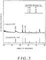
- Fig. 5 shows an XRD profile of the vanadium oxide composite body with aluminum as a solid solution obtained through the first process.
- a peak is observed at the same position as in the XRD profile of vanadium oxide (V 2 O 3 ) of ICDD, and it is confirmed that, as a result of the first process, the vanadium oxide with aluminum as a solid solution (V 1.8 Al 0.2 O 3 ) has the same crystal structure as the vanadium oxide (V 2 O 3 ), and impurities are not formed.
- Fig. 6 shows EDX surface analysis results of the lithium vanadium phosphate with aluminum as a solid solution obtained through the second process.
- the colored regions in the image indicate the distribution state of O, P, C, V, and Al. From Fig. 6 , it can be observed that O, P, and V indicating the lithium vanadium phosphate are dispersed in the same manner as the Al. In this way, in the lithium vanadium phosphate with aluminum as a solid solution obtained from the first process and the second process, it is understood that the aluminum is dispersed approximately uniformly without being unevenly distributed in the vanadium phosphate and forms a solid solution.
- Fig. 7 is an HRTEM image of the lithium vanadium phosphate composite body with aluminum as a solid solution bonded to the CNF surface.
- the arrows indicate the particles of the lithium vanadium phosphate with aluminum as a solid solution, and the rod-shaped substances are the CNF.
- the lithium vanadium phosphate with aluminum as a solid solution is dispersed in particle form with a particle size from 10 nm to 100 nm.
- an image is obtained in which the particles and the CNF are focused on, it can be confirmed that the particles and the CNF are at the same height, and from this it is understood that these particles are bonded to the surface of the CNF.
- the lithium vanadium phosphate with aluminum as a solid solution is in a state of being bonded to the surface of the CNF in particle form with a particle size from 10 nm to 100 nm.
- Fig. 8 shows an HRTEM image of the lithium vanadium phosphate and a particle size distribution.
- Fig. 8 shows an HRTEM image and a particle size distribution of each of (a) a composite body of V 2 O 3 /CNF, (b) a composite body of V 1.8 Al 0.2 O 3 /CNF, (c) a composite body of Li 3 V 2 (PO 4 ) 3 /CNF, and (d) a composite body of Li 3 V 1.8 Al 0.2 (PO 4 ) 3 /CNF.
- the particle size of the lithium vanadium phosphate carried by the CNF is obtained by measuring the particle size of the particles of the lithium vanadium phosphate images in the HRTEM image.
- the number of particles is also obtained by counting the number of lithium vanadium phosphate particles in this HRTEM image.
- the particle size distributions in Fig. 8 are created from the particle size measured from the HRTEM image and the number of particles counted in the HRTEM image.
- This composite body powder was introduced into SUS mesh welded on an SUS board along with polyvinylidene fluoride PVDF serving as a binder, thereby forming a working electrode W.E.
- the introduction ratio for Li 3 V 1.8 Al 0.2 (PO 4 ) 3 :CNF:PVDF was 63:27:10, by weight.
- a separator and an opposite pole C.E. were provided on the working electrode W.E., along with a Li foil serving as a reference pole.
- An electrolyte was provided as a cell permeated with 1.0 M lithium hexafluorophosphate (LiPF 6 )/ethylene carbonate (EC) and dimethyl carbonate (DEC). The ratio of LIPF 6 /EC:DEC was 1:1 by weight.
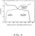
- Fig. 9 is a graph showing the charging/discharging characteristic of the cathode material including the lithium vanadium phosphate with aluminum as a solid solution.
- the horizontal axis indicates the discharge capacity and the vertical axis indicates the potential. As shown in Fig.
- the charge capacity was 126 mAhg -1 , which is slightly higher than the theoretical capacity 117.9 mAhg -1 calculated when the theoretical capacity is reduced by an amount corresponding to doping with aluminum, and this indicates a capacity expression rate of 107%.
- the discharge capacity was 124 mAhg -1 , which is slightly higher than the theoretical capacity 117.9 mAhg -1 , and this indicates a capacity expression rate of 105%.
- Fig. 10 shows a first process in a manufacturing method of a lithium vanadium phosphate composite body of the first reference example using an alkali clumping precipitation technique.
- CNF and vanadium chloride (III) were added to distilled water (H 2 O), and the UC process was performed on this mixture.
- sodium hydroxide (NaOH) was added to adjust the mixture to have a pH of 7, thereby hydrolyzing the vanadium chloride (III) and generating vanadium hydroxide (III) (V(OH) 3 ).
- the UC process was performed for 2 minutes.
- the impurities were then filtered from the solution and vacuum drying was performed at 80°C, after which sintering was performed for 5 minutes at 800°C in a nitrogen atmosphere. With this sintering, a dehydration condensation reaction occurred in the vanadium hydroxide (III), and vanadium oxide (III) (V 2 O 3 ) bonded to the surface of the CNF was formed.
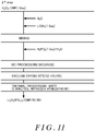
- Fig. 11 shows a second process in the manufacturing method of a lithium vanadium phosphate composite body of the first reference example using the alkali clumping precipitation technique.
- an equivalent weight of 1.5 of lithium acetate (LiOAc) and distilled water was added to and mixed with a solution containing an equivalent weight of 1.0 of the composite body including the CNF and the vanadium oxide (III) (V 2 O 3 ), and then an equivalent weight of 1.5 of phosphate (H 3 PO 4 ) and distilled water was added and the UC process was performed for 5 minutes.
- the obtained mixed solution was dried overnight at 80°C in a vacuum, and was then sintered for 5 minutes at 800°C in a nitrogen atmosphere.
- crystallization of the lithium vanadium phosphate progresses, and a composite body powder is obtained in which the lithium vanadium phosphate is carried by the CNF.
- Fig. 12 is an HRTEM image showing the entire image of the lithium vanadium phosphate manufactured using the alkali clumping precipitation technique.
- Fig. 13 is an HRTEM image showing an enlarged portion of the lithium vanadium phosphate manufactured using the alkali clumping precipitation technique.
- the lithium vanadium phosphate manufactured using the alkali clumping precipitation technique is a mixture of plate-shaped crystals with sizes from 50 nm to 500 nm and particle-shaped crystals with sizes from 3 nm to 6 nm bonded to the CNF.
- This composite body powder was introduced into SUS mesh welded on an SUS board along with polyvinylidene fluoride PVDF serving as a binder, thereby forming a working electrode W.E.
- the introduction ratio for Li 3 V 2 (PO 4 ) 3 :CNF:PVDF was 63:27:10, by weight.
- a separator and an opposite pole C.E. were provided on the working electrode W.E., along with a Li foil serving as a reference pole.
- An electrolyte was provided as a cell permeated with 1.0 M lithium hexafluorophosphate (LiPF 6 )/ethylene carbonate (EC) and dimethyl carbonate (DEC). The ratio of LIPF 6 /EC:DEC was 1:1 by weight.
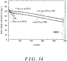
- FIG. 14 shows the discharge rate characteristics.
- the horizontal axis indicates the C rate and the vertical axis indicates the discharge capacity.
- conventional discharge rate characteristics that have been disclosed up to now are included in the graph.
- the cathode material made of the composite body of CNF and the lithium vanadium phosphate with aluminum as a solid solution has a discharge capacity of 85 mAhg -1 at a high C rate of 480 C, which is a significant improvement over the discharge capacity at the C rate disclosed in X.
- the cathode material according to the reference example had a discharge capacity of 80 mAhg -1 at 480 C, and the cathode material shown in the present embodiment example was able to ensure a higher discharge capacity than the first reference example.
- Fig. 15 is a schematic view of a crystal structure of the lithium vanadium phosphate with aluminum as a solid solution.
- the left side of the drawing shows the crystal structure of lithium vanadium phosphate and the right side of the drawing shows the crystal structure of lithium vanadium phosphate including aluminum.
- the lithium vanadium phosphate has an Na super ionic conductor structure in which an octahedron of VO 6 and a tetrahedron of PO 4 share a vertex and are arranged three-dimensionally.
- the lithium vanadium phosphate with aluminum as a solid solution has an Na super ionic conductor structure that is the same as that of the lithium vanadium phosphate, and includes an octahedron of AlO 6 replaced by aluminum at sites of vanadium atoms in a portion thereof.
- the lithium vanadium phosphate with aluminum as a solid solution is expressed by the general formula Li 3 V (2-x) Al x (PO 4 ) 3 , where 0 ⁇ x ⁇ 0.5.
- the valence of the vanadium changes from 3 to 4 or 5, due to the removal and insertion of lithium ions that accompanies the charging/discharging.
- the aluminum that is a solid solution is not involved in the electrochemical reaction. Therefore, even when removal and insertion of lithium ions occurs along with the charging/discharging, the valence of the aluminum remains at 3 without changing.
- the crystal structure of the lithium vanadium phosphate with aluminum as a solid solution it is believed that the crystal structure in which aluminum atoms have replaced the atoms at the sites of vanadium atoms does not experience a change in volume, since the valence of the aluminum does not change due to the removal and insertion of lithium. In this way, it is believed that in the vanadium phosphate crystal structure including a portion that is a crystal structure that does not experience a change in volume, even when lithium ions are removed and inserted along with the charging/discharging of a secondary battery, the aluminum restricts the change in volume in other crystal structures.
- the diffusion rate of the lithium ions can be increased and the discharge capacity characteristic at a high C rate can be increased compared to lithium vanadium phosphate without aluminum as a solid solution.
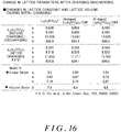
- Fig. 16 is a table showing lattice parameter changes of the cathode material before and after charging/discharging and change in volume calculated from these lattice parameters.
- An XRD measurement of the cathode material was made before and after the charging/discharging, and upon calculating lattice parameter change and the volume change (volume strain), the volume change of the lithium vanadium phosphate of the first reference example was found to be 6.4% and the volume change of the lithium vanadium phosphate with aluminum as a solid solution was found to be 4.4%. In this way, it was confirmed that, by including the aluminum as a solid solution, it is possible to restrict the volume change of the crystal structure caused by the removal and insertion of lithium that accompanies the charging/discharging of the secondary battery.
- Fig. 17 is a graph showing a discharge cycle characteristic.
- Fig. 17 shows the discharge cycle characteristic of the cathode material including the lithium vanadium phosphate with aluminum as a solid solution.
- the horizontal axis indicates the number of cycles and the vertical axis indicates the discharge capacity.
- the cathode material including the lithium vanadium phosphate with aluminum as a solid solution maintained a discharge capacity of 100 mAhg -1 , indicating a capacity maintenance ratio of 89%. From this, it is understood that the cathode material including lithium vanadium phosphate has excellent durability.
- an equivalent weight of 0.05 of aluminum nitrate was mixed with an equivalent weight of 0.95 of ammonium metavanadate, in the mixed solution used in the first process, to create cathode material made from a composite body powder of carbon nanofiber and lithium vanadium phosphate with 5% aluminum as a solid solution (LiV 1.9 Al 0.1 (PO 4 ) 3 ).
- a working electrode W.E and a cell were created using the same procedure as in the first embodiment example.
- a C.C. mode constant current mode set in which the discharge rate is 1 C and the working voltage of this cell is from 2.5 V to 4.3 V, the charging/discharging characteristic was examined.
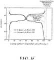
- Fig. 18 shows charging/discharging characteristics of the cathode material including the lithium vanadium phosphate composite body.
- Fig. 18 shows the charging/discharging characteristic of a cell including the cathode material that includes the lithium vanadium phosphate with 5% aluminum as a solid solution according to the second embodiment example and the charging/discharging characteristic of a cell including the cathode material that includes the lithium vanadium phosphate according to the first reference example.
- the horizontal axis indicates the discharge capacity and the vertical axis indicates the potential.
- the discharge capacity of the cathode material including cathode material that includes the lithium vanadium phosphate with 5% aluminum as a solid solution was 123 mAhg -1 , which is slightly lower than the theoretical capacity 125 mAhg -1 calculated when the theoretical capacity is reduced by an amount corresponding to doping with aluminum, and this indicates a capacity expression rate of 95.2%.
- the discharge capacity of the cathode material including lithium vanadium phosphate according to the first reference example was 123 mAhg -1 , which is slightly lower than the theoretical capacity 131 mAhg -1 , and this indicates a capacity expression rate of 90.8%.
- the cathode material including the lithium vanadium phosphate with 5% aluminum as a solid solution exhibited a higher capacity expression rate than the cathode material including the lithium vanadium phosphate without aluminum as a solid solution.
- Fig. 19 shows charge rate characteristics.
- Fig. 19 shows the charge rate characteristic of the cathode material including the lithium vanadium phosphate with 5% aluminum as a solid solution and the charge rate characteristic of the cathode material including the lithium vanadium phosphate.
- the horizontal axis indicates the C rate and the vertical axis indicates the charge capacity.
- the cathode material including the lithium vanadium phosphate with 5% aluminum as a solid solution exhibited a higher charge capacity than the cathode material including the lithium vanadium phosphate at a high C rate from 50 C to 480 C. In this way, it is understood that the cathode material including the lithium vanadium phosphate with 5% aluminum as a solid solution can obtain a higher charge capacity characteristic at a high C rate than the cathode material including the lithium vanadium phosphate without aluminum as a solid solution.
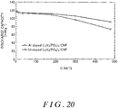
- Fig. 20 shows discharge rate characteristics.
- Fig. 20 shows the discharge rate characteristic of the cathode material including the lithium vanadium phosphate with 5% aluminum as a solid solution and the discharge rate characteristic of the cathode material including the lithium vanadium phosphate.
- the horizontal axis indicates the C rate and the vertical axis indicates the discharge capacity.
- the cathode material including the lithium vanadium phosphate with 5% aluminum as a solid solution exhibited a higher discharge capacity than the cathode material including the lithium vanadium phosphate at a high C rate from 50 C to 480 C. In this way, it is understood that the cathode material including the lithium vanadium phosphate with 5% aluminum as a solid solution can obtain a higher discharge capacity characteristic at a high C rate than the cathode material including the lithium vanadium phosphate without aluminum as a solid solution.
- Fig. 21 shows discharge cycle characteristics.
- Fig. 21 shows the cycle characteristic of the cathode material including the lithium vanadium phosphate with 5% aluminum as a solid solution and the cycle characteristic of the cathode material including the lithium vanadium phosphate.
- the horizontal axis indicates the number of cycles and the vertical axis indicates the discharge capacity.
- the cathode material including the lithium vanadium phosphate with 5% aluminum as a solid solution maintained a discharge capacity of 100 mAhg -1 , indicating a capacity maintenance ratio of 92.4%.
- the cathode material including the lithium vanadium phosphate maintained a discharge capacity of 96 mAhg -1 , indicating a capacity maintenance ratio of 89.4%.
- the cathode material including lithium vanadium phosphate with 5% aluminum as a solid solution has better durability than the cathode material including lithium vanadium phosphate without aluminum as a solid solution.
- the cathode material including lithium vanadium phosphate with 5% aluminum as a solid solution is superior to the cathode material including lithium vanadium phosphate without aluminum as a solid solution with respect to the capacity expression rate, the charge rate characteristic, the discharge rate characteristic, and the durability.
- the aluminum can restrict volume change of the crystal structure of the vanadium phosphate due to the removal and insertion of lithium, and can stabilize the crystal structure. Therefore, the cathode material including lithium vanadium phosphate with 5% aluminum as a solid solution has an excellent capacity expression rate, charge rate characteristic, discharge rate characteristic, and durability.
- Fig. 22 is a flow chart showing the manufacturing procedure of a first process of the lithium vanadium phosphate composite body with the gallium or indium as a solid solution.
- a mixed solvent was created by adding an equivalent weight of 0.95 of the ammonium metavanadate (NH 4 VO 3 ), an equivalent weight of 1.0 of citric acid, an equivalent weight of 4.0 of ethylene glycol, an equivalent weight of 0.05 of gallium nitrate or an equivalent weight of 0.05 of indium nitrate, and the CNF to distilled water (H 2 O).
- the UC process was performed on the created mixture in an environment with a temperature of 80°C.
- the UC process included rotating the inner tube 120 with a rotational speed of 50 m/s to apply a centrifugal force of 66000 N(kgms -2 ) to the mixture over a period of 5 minutes.
- the impurities were filtered from the mixed solution and vacuum drying was performed at 130°C for 12 hours, after which thermal processing was performed for 3 hours at 300°C. After this, sintering was performed for 30 minutes at 800°C in a nitrogen atmosphere. In this way, bonding to the CNF surface is achieved to form vanadium oxide with indium or vanadium as a solid solution (V 1.9 M 0.1 O 3 ).
- the second process is the same as the process described in Fig. 4 , and therefore a detailed description of the second process is omitted.
- Fig. 23 shows charging/discharging characteristics.
- Fig. 23 shows the charging/discharging characteristic of the cathode material including the lithium vanadium phosphate with gallium as a solid solution and the charging/discharging characteristic of the cathode material including the lithium vanadium phosphate with indium as a solid solution.
- the vertical axis indicates the potential and the horizontal axis indicates the discharge capacity.
- the lithium vanadium phosphate with gallium as a solid solution and the lithium vanadium phosphate with indium as a solid solution were electrochemically active.
- Fig. 24 shows discharge rate characteristics.
- Fig. 24 shows the discharge rate characteristics of the cathode material including the lithium vanadium phosphate with gallium as a solid solution, the cathode material including the lithium vanadium phosphate with indium as a solid solution, and the cathode material including the lithium vanadium phosphate.
- the horizontal axis indicates the C rate and the vertical axis indicates the discharge capacity. From Fig. 24 , it is understood that the discharge capacity of the cathode material including the lithium vanadium phosphate with gallium as a solid solution is lower than the discharge capacity of the cathode material including the lithium vanadium phosphate at a low C rate of 1 C. This is caused by a decrease in the theoretical capacity as a result of including a solid solution of gallium, which is not involved in the electrochemical reaction.
- the discharge capacity of the cathode material including the lithium vanadium phosphate with gallium as a solid solution is higher than that of the cathode material including the lithium vanadium phosphate.
- the cathode material including the lithium vanadium phosphate with gallium as a solid solution is understood to realize a high discharge capacity characteristic at a high C rate.
- the discharge capacity of the cathode material including the lithium vanadium phosphate with indium as a solid solution is lower than the discharge capacity of the cathode material including the lithium vanadium phosphate at a low C rate of 1 C.
- the discharge capacity of the cathode material including the lithium vanadium phosphate with indium as a solid solution is higher than that of the cathode material including the lithium vanadium phosphate.
- the cathode material including the lithium vanadium phosphate with indium as a solid solution is understood to realize a high discharge capacity characteristic at a high C rate.
- Fig. 25 shows charge rate characteristics.
- Fig. 25 shows the charge rate characteristics of the cathode material including the lithium vanadium phosphate with gallium as a solid solution, the cathode material including the lithium vanadium phosphate with indium as a solid solution, and the cathode material including the lithium vanadium phosphate.
- the horizontal axis indicates the C rate and the vertical axis indicates the charge capacity. From Fig. 25 , it is understood that the charge capacity of the cathode material including the lithium vanadium phosphate with gallium as a solid solution is lower than the charge capacity of the cathode material including the lithium vanadium phosphate at a low C rate of 1 C. However, at a high C rate of 480 C, the charge capacity of the cathode material including the lithium vanadium phosphate with gallium as a solid solution is higher than that of the cathode material including the lithium vanadium phosphate. In this way, the cathode material including the lithium vanadium phosphate with gallium as a solid solution is understood to realize a high charge capacity characteristic at a high C rate.
- the charge capacity of the cathode material including the lithium vanadium phosphate with indium as a solid solution is lower than the charge capacity of the cathode material including the lithium vanadium phosphate at a low C rate of 1 C.
- the charge capacity of the cathode material including the lithium vanadium phosphate with indium as a solid solution is higher than that of the cathode material including the lithium vanadium phosphate.
- the cathode material including the lithium vanadium phosphate with indium as a solid solution is understood to realize a high charge capacity characteristic at a high C rate.
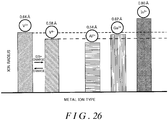
- Fig. 26 is a drawing for describing the ion radius of the metal ions.
- the height in the bar graph indicates the size of the ion radius.
- a high bar graph indicates a large ion radius
- a low bar graph indicates a small ion radius.
- the ion radius of the aluminum as a solid solution in the vanadium is 0.54 .
- the ion radius of the gallium as a solid solution in the vanadium is 0.62
- the ion radius of the indium as a solid solution in the vanadium is 0.80 .
- any one of the metals forming a solid solution in the vanadium in the present embodiment example is a metal that has a valence of 3 in the same manner as the vanadium ions and does not change its valence due to the removal and insertion of lithium ions, and it is possible to improve the capacity characteristic in a high C rate condition regardless of the size of the ion radius in these metals.
- Fig. 27 is a graph showing a theoretical capacity of the lithium vanadium phosphate with aluminum as a solid solution.
- the aluminum is not involved in the electrochemical reaction, and therefore the theoretical capacity of the cathode material was calculated with the theoretical capacity being reduced by an amount corresponding to doping with aluminum.
- the upper limit of the aluminum solid solution amount to be less than or equal to 25%, the lithium vanadium phosphate with aluminum as a solid solution can be guaranteed to have a theoretical capacity of 100 mAhg -1 .
- the lithium vanadium phosphate with aluminum as a solid solution is expressed by the general formula Li 3 V (2-x) Al x (PO 4 ) 3 , it is preferable that 0 ⁇ x ⁇ 0.5.
- the lithium vanadium phosphate includes aluminum, it is possible to increase the discharge capacity characteristic at a high C rate with the pillar structure described above.
- the theoretical capacity is reduced when aluminum is included, but by making x less than or equal to 0.5, it is possible to make the upper limit of the aluminum solid solution amount less than or equal to 25%. In this way, it is possible to guarantee a theoretical capacity greater than or equal to 100 mAhg -1 for the lithium vanadium phosphate with aluminum as a solid solution.
- the present embodiment shows an example of lithium vanadium phosphate with aluminum or the like as a solid solution, but the aluminum or the like does not need to be a solid solution.
- Lithium vanadium phosphate in which the aluminum is not a solid solution is manufactured using the Pechini method in the same manner as the present embodiment example, but the aluminum nitrate serving as the aluminum source is not included.
- Fig. 28 is an HRTEM image of a lithium vanadium phosphate composite body in which the aluminum is not a solid solution, manufactured using the Pechini method.
- the black portion indicates the lithium vanadium phosphate composite body and the light gray portion indicates the CNF.
- the lithium vanadium phosphate obtained through the manufacturing method shown in the present embodiment example is dispersed as particle-shaped crystals with a particle size from 10 nm to 200 nm that are each bonded to the CNF.
- the lithium vanadium phosphate composite body in which the aluminum is not a solid solution is dispersed as particle-shaped crystals with a particle size from 10 nm to 200 nm that are bonded to the CNF, and this dispersion state has high durability and high discharge capacity at a high C rate.
- Fig. 29 shows the discharge cycle characteristic.
- Fig. 29 shows the discharge cycle characteristic of the lithium vanadium phosphate composite body in which the aluminum is not a solid solution, manufactured using the Pechini method.
- the cathode material formed from the lithium vanadium phosphate composite body in which particle-shaped crystals with a particle size from 10 nm to 200 nm, and manufactured using the Pechini method was able to maintain a discharge capacity of 99 mAhg -1 even after 9500 cycles of charging/discharging were performed.
- the cathode material formed from the lithium vanadium phosphate composite body manufactured using the alkali clumping precipitation technique shown in the first reference example had a discharge capacity of 95 mAhg -1 after 9500 cycles of charging/discharging were performed.
- the alkali clumping precipitation technique shown in the first reference example damages the surface of the conductive carbon material or the VCl 3 which generates the hydrogen chloride or chlorine resulting from the dissolution of the vanadium chloride, and so it is necessary to use NaOH providing an irreversible capacity.
- the manufacturing method shown in the first embodiment example does not use VCl 3 , and therefore hydrogen chloride and chlorine are not generated, so that the manufacturing method is more environmentally friendly.
- manufacturing is performed without adding NaOH, the surface of the conductive carbon material is not damaged. Therefore, it is possible to restrict the increase of the initial irreversible capacity, thereby achieving a favorable durability.
- CNF is used as the conductive carbon material.
- the conductive carbon material is not limited to CNF, and may be Ketjen black (Registered Trademark).
- Ketjen black (Registered Trademark) is conductive carbon black having a hollow shell structure, and is suitable as a conductive carbon material in the same manner as CNF.
Landscapes
- Chemical & Material Sciences (AREA)
- Chemical Kinetics & Catalysis (AREA)
- Electrochemistry (AREA)
- General Chemical & Material Sciences (AREA)
- Inorganic Chemistry (AREA)
- Composite Materials (AREA)
- Crystallography & Structural Chemistry (AREA)
- Engineering & Computer Science (AREA)
- Materials Engineering (AREA)
- Battery Electrode And Active Subsutance (AREA)
Claims (12)
- Matière de cathode fabriquée par un procédé comprenant :une premier processus incluant une étape d'application d'une contrainte de cisaillement et d'une force centrifuge à l'intérieur d'un récipient réactionnel de filage à une solution aqueuse d'un mélange comportant une source de vanadium, une matière carbonée conductrice, un composé organique ayant une pluralité de groupes carboxyles et un alcool ayant une pluralité de groupes hydrogène, pour lier de l'oxyde de vanadium à une surface de la matière carbonée conductrice ; etun deuxième processus incluant une étape d'addition d'une source de phosphate et d'une source de lithium au mélange et d'application d'une contrainte de cisaillement et d'une force centrifuge au mélange à l'intérieur du récipient réactionnel de filage, pour produire du phosphate de lithium et de vanadium avec des formes de particules liées à la surface de la matière carbonée conductrice, oùle premier processus inclut en outre, après l'étape de liaison de l'oxyde de vanadium à la surface de la matière carbonée conductrice,une étape de séchage du mélange ; etune étape de frittage du mélange ; etle deuxième processus comporte en outre, après l'étape de production du phosphate de lithium et de vanadium avec des formes de particules liées à la surface de la matière carbonée conductrice :une étape de séchage du phosphate de lithium et de vanadium ; etune étape de frittage du phosphate de lithium et de vanadium, où la matière de cathode comprend :du phosphate de lithium et de vanadium incluant du vanadium avec une valence qui varie entre 3 et 5 à cause du retrait et de l'insertion d'ions lithium ; etde la matière carbonée conductrice ;le phosphate de lithium et de vanadium est lié à une surface de la matière carbonée conductrice,le phosphate de lithium et de vanadium comporte un métal M choisi parmi l'aluminium, le gallium et l'indium, le métal forme une solution solide dans le phosphate de lithium et de vanadium, le phosphate de lithium et de vanadium incluant le métal peut être exprimé par une formule générale Li3V2-xMx(PO4)3 ou LiV2-xMx(PO4)3, où 0 < x ≤ 0,5, et 90 % ou plus de phosphate de lithium et de vanadium pour le poids total sont des cristaux de forme particulaire avec des diamètres de 10 nm à 200 nm.
- Matière de cathode selon l'une quelconque des revendications précédentes, dans laquelle le diamètre du phosphate de lithium et de vanadium est de 10 nm 100 nm.
- Matière de cathode selon l'une quelconque des revendications précédentes, dans laquelle la matière carbonée conductrice est de la nanofibre de carbone.
- Matière de cathode selon l'une quelconque des revendications précédentes, dans laquelle la matière carbonée conductrice est du noir de carbone conducteur ayant une structure en coque creuse.
- Matière de cathode selon l'une quelconque des revendications précédentes, dans laquelle le métal est l'aluminium.
- Matière de cathode selon les revendications précédentes, dans laquelle le phosphate de lithium et de vanadium incluant l'aluminium peut être exprimé par une formule générale LiV2 -xAlx(PO4)3, où 0 < x ≤ 0,5.
- Batterie secondaire (10) comprenant une cathode (18) incluant la matière de cathode selon l'une quelconque des revendications précédentes, une anode (20) et un conducteur d'ion (14) et un séparateur (16).
- Procédé de fabrication d'une matière de cathode comprenant :une premier processus incluant une étape d'application d'une contrainte de cisaillement et d'une force centrifuge à l'intérieur d'un récipient réactionnel de filage à une solution aqueuse d'un mélange comportant une source de vanadium, et un métal M choisi parmi une source d'aluminium, une source de gallium et une source d'indium, une matière carbonée conductrice, un composé organique ayant une pluralité de groupes carboxyles et un alcool ayant une pluralité de groupes hydrogène, pour lier de l'oxyde de vanadium à une surface de la matière carbonée conductrice ; etun deuxième processus incluant une étape d'addition d'une source de phosphate et d'une source de lithium au mélange et d'application d'une contrainte de cisaillement et d'une force centrifuge au mélange à l'intérieur du récipient réactionnel de filage, pour produire du phosphate de lithium et de vanadium avec des formes de particules liées à la surface de la matière carbonée conductrice, le phosphate de lithium et de vanadium comportant(i) le métal étant exprimé par une formule générale Li3V2-xMx(PO4)3 ou LiV2-xMx(PO4)3, où 0 < x ≤ 0,5, où le métal forme une solution solide dans le phosphate de lithium et de vanadium,(ii) du vanadium avec une valence qui varie entre 3 et 5 à cause du retrait et de l'insertion d'ions lithium, et 90 % ou plus de phosphate de lithium et de vanadium pour le poids total sont des cristaux de forme particulaire avec des diamètres de 10 nm à 200 nm, oùle premier processus comporte en outre, après l'étape de liaison de l'oxyde de vanadium à la surface de la matière carbonée conductrice :une étape de séchage du mélange ; etune étape de frittage du mélange ; etle deuxième processus comporte en outre, après l'étape de production du phosphate de lithium et de vanadium avec des formes de particules liées à la surface de la matière carbonée conductrice :une étape de séchage du phosphate de lithium et de vanadium ; etune étape de frittage du phosphate de lithium et de vanadium.
- Procédé de fabrication d'une matière de cathode selon la revendication précédente, dans lequel l'étape de séchage du mélange comporte en outre une étape d'évaporation :du composé organique ayant la pluralité de groupes carboxyles ;de l'alcool ayant la pluralité de groupes hydrogène ; etd'un composé organique produit par une réaction d'estérification entre le composé organique ayant la pluralité de groupes carboxyles et l'alcool ayant la pluralité de groupes hydrogène.
- Procédé de fabrication d'une matière de cathode selon l'une quelconque des revendications précédentes, dans lequel, dans l'étape de liaison de l'oxyde de vanadium à la surface de la matière carbonée conductrice, la source d'aluminium est choisie en tant que métal.
- Procédé de fabrication d'une matière de cathode selon l'une quelconque des revendications précédentes, dans lequel la source de vanadium et la source d'aluminium sont mélangées l'une à l'autre de sorte que le nombre de moles d'aluminium dans la source d'aluminium est dans une plage supérieure à 0 à inférieure ou égale à 0,33 pour 1 mole de vanadium dans la source de vanadium.
- Procédé de fabrication d'une batterie secondaire, comprenant le procédé de fabrication de la matière de cathode selon l'une quelconque des revendications de procédé précédentes.
Applications Claiming Priority (2)
| Application Number | Priority Date | Filing Date | Title |
|---|---|---|---|
| JP2014107342 | 2014-05-23 | ||
| PCT/JP2015/064730 WO2015178479A1 (fr) | 2014-05-23 | 2015-05-22 | Matière d'électrode positive, batterie rechargeable, procédé de fabrication de matière d'électrode positive, et procédé de fabrication de batterie rechargeable |
Publications (3)
| Publication Number | Publication Date |
|---|---|
| EP3147975A1 EP3147975A1 (fr) | 2017-03-29 |
| EP3147975A4 EP3147975A4 (fr) | 2017-05-31 |
| EP3147975B1 true EP3147975B1 (fr) | 2021-07-07 |
Family
ID=54554138
Family Applications (1)
| Application Number | Title | Priority Date | Filing Date |
|---|---|---|---|
| EP15795693.9A Active EP3147975B1 (fr) | 2014-05-23 | 2015-05-22 | Matière d'électrode positive, batterie rechargeable, procédé de fabrication de matière d'électrode positive, et procédé de fabrication de batterie rechargeable |
Country Status (4)
| Country | Link |
|---|---|
| EP (1) | EP3147975B1 (fr) |
| JP (1) | JP6650871B2 (fr) |
| CN (1) | CN106575767B (fr) |
| WO (1) | WO2015178479A1 (fr) |
Families Citing this family (5)
| Publication number | Priority date | Publication date | Assignee | Title |
|---|---|---|---|---|
| CN106410193A (zh) * | 2016-11-11 | 2017-02-15 | 攀钢集团攀枝花钢铁研究院有限公司 | 制备钠离子电池用正极材料磷酸钒钠及磷酸钒的方法 |
| CN106328943A (zh) * | 2016-11-11 | 2017-01-11 | 攀钢集团攀枝花钢铁研究院有限公司 | 一种制备锂离子电池正极材料磷酸钒锂的方法 |
| JP7609562B2 (ja) * | 2020-03-31 | 2025-01-07 | 日本ケミコン株式会社 | 電極材料および電極材料の製造方法 |
| CN112233911B (zh) * | 2020-10-16 | 2022-07-15 | 成都先进金属材料产业技术研究院股份有限公司 | 二氧化钒纳米碳纤维复合材料及其制备方法和用途 |
| CN114572957B (zh) * | 2022-02-22 | 2023-03-28 | 鞍钢集团北京研究院有限公司 | 一种磷酸钒钠材料的制备方法 |
Family Cites Families (10)
| Publication number | Priority date | Publication date | Assignee | Title |
|---|---|---|---|---|
| JP2949229B1 (ja) * | 1998-09-16 | 1999-09-13 | 大阪大学長 | 燐酸リチウム・バナジウム複合化合物及び同複合化合物からなるリチウムイオン二次電池用正極材料 |
| CA2638410A1 (fr) * | 2008-07-28 | 2010-01-28 | Hydro-Quebec | Materiau d'electrode composite |
| JP5604217B2 (ja) * | 2010-08-09 | 2014-10-08 | 日本化学工業株式会社 | リン酸バナジウムリチウム炭素複合体の製造方法 |
| US8808909B2 (en) * | 2011-06-23 | 2014-08-19 | Melecular Rebar Design, LLC | Lithium ion batteries using discrete carbon nanotubes, methods for production thereof and products obtained therefrom |
| JP5871543B2 (ja) * | 2011-09-29 | 2016-03-01 | 富士重工業株式会社 | 改質リン酸バナジウムリチウム炭素複合体、その製造方法、リチウム二次電池正極活物質及びリチウム二次電池 |
| CN103891013B (zh) * | 2011-10-29 | 2016-11-09 | 日本贵弥功株式会社 | 电极材料的制造方法 |
| JP6358493B2 (ja) * | 2011-11-15 | 2018-07-18 | デンカ株式会社 | 複合粒子、その製造方法、二次電池用電極材料及び二次電池 |
| JP5921929B2 (ja) * | 2012-03-28 | 2016-05-24 | 日本ケミコン株式会社 | 二次電池用電極材料及びその製造方法 |
| KR101436828B1 (ko) * | 2012-04-25 | 2014-09-18 | 전남대학교산학협력단 | 고율 충방전 조건에서 향상된 레이트 특성을 나타내는 전기화학소자용 고용량 활물질의 제조 방법 |
| WO2014051147A1 (fr) * | 2012-09-28 | 2014-04-03 | 日本ケミコン株式会社 | Matériau d'électrode et son procédé de fabrication |
-
2015
- 2015-05-22 CN CN201580037607.XA patent/CN106575767B/zh active Active
- 2015-05-22 EP EP15795693.9A patent/EP3147975B1/fr active Active
- 2015-05-22 WO PCT/JP2015/064730 patent/WO2015178479A1/fr not_active Ceased
- 2015-05-22 JP JP2016521160A patent/JP6650871B2/ja active Active
Non-Patent Citations (1)
| Title |
|---|
| None * |
Also Published As
| Publication number | Publication date |
|---|---|
| CN106575767B (zh) | 2020-02-21 |
| EP3147975A4 (fr) | 2017-05-31 |
| CN106575767A (zh) | 2017-04-19 |
| JP6650871B2 (ja) | 2020-02-19 |
| WO2015178479A1 (fr) | 2015-11-26 |
| EP3147975A1 (fr) | 2017-03-29 |
| JPWO2015178479A1 (ja) | 2017-04-20 |
Similar Documents
| Publication | Publication Date | Title |
|---|---|---|
| Wang et al. | Facile synthesis of porous LiMn2O4 spheres as cathode materials for high-power lithium ion batteries | |
| Pang et al. | Mesoporous NaTi 2 (PO 4) 3/CMK-3 nanohybrid as anode for long-life Na-ion batteries | |
| EP3158600B1 (fr) | Électrode nanostructurée en silicium poreux et procédé associé | |
| KR101846587B1 (ko) | 금속 산화물 나노 입자와 카본의 복합체, 그의 제조 방법, 이 복합체를 이용한 전극 및 전기 화학 소자 | |
| Liu et al. | Electrospun Sn-doped LiTi 2 (PO 4) 3/C nanofibers for ultra-fast charging and discharging | |
| Yang et al. | Synthesis and electrochemical properties of Zn-doped, carbon coated lithium vanadium phosphate cathode materials for lithium-ion batteries | |
| Li et al. | Structural and electrochemical characteristics of SiO2 modified Li4Ti5O12 as anode for lithium-ion batteries | |
| Guo et al. | TiO 2 (B) nanofiber bundles as a high performance anode for a Li-ion battery | |
| JP2011181452A (ja) | リチウムイオン電池用正極活物質の製造方法及びリチウムイオン電池用電極並びにリチウムイオン電池 | |
| EP3147975B1 (fr) | Matière d'électrode positive, batterie rechargeable, procédé de fabrication de matière d'électrode positive, et procédé de fabrication de batterie rechargeable | |
| Zhou et al. | Comparative study of LiMnPO 4 cathode materials synthesized by solvothermal methods using different manganese salts | |
| Ma et al. | Facile solvothermal synthesis of anatase TiO 2 microspheres with adjustable mesoporosity for the reversible storage of lithium ions | |
| Liu et al. | Hierarchically porous anatase TiO 2 microspheres composed of tiny octahedra with enhanced electrochemical properties in lithium-ion batteries | |
| KR20160091172A (ko) | 잔류 리튬이 감소된 양극활물질의 제조 방법 및 이에 의하여 제조된 잔류 리튬이 감소된 양극활물질 | |
| WO2010150857A1 (fr) | Matériau d'électrode nanoporeux composite, son procédé de fabrication et batterie secondaire au lithium | |
| Ding et al. | Advanced and safer lithium-ion battery based on sustainable electrodes | |
| He et al. | Template-assisted molten-salt synthesis of hierarchical lithium-rich layered oxide nanowires as high-rate and long-cycling cathode materials | |
| Zhu et al. | Designed synthesis of LiNi 0.5 Mn 1.5 O 4 hollow microspheres with superior electrochemical properties as high-voltage cathode materials for lithium-ion batteries | |
| JP6119123B2 (ja) | 活物質材料、電池、および活物質材料の製造方法 | |
| Liu et al. | Enhancement of cathode superior kinetics and Li-storage properties of LiMn0. 5Fe0. 5PO4@ C cathode materials by Ni doping strategy | |
| Zhang et al. | Enhanced electrochemical properties of MgF2 and C co-coated Li3V2 (PO4) 3 composite for Li-ion batteries | |
| Xia et al. | Synthesis and electrochemical properties of W-doped Li3V2 (PO4) 3/C cathode materials for lithium ion batteries | |
| US10640391B2 (en) | LTO coated LRMO cathode and synthesis | |
| Liu et al. | A promising sol-gel method to synthesize NaVO3 as anode material for lithium ion batteries | |
| JP6186568B2 (ja) | 電気化学デバイス電極材料用一次元ナノ構造体、エレクトロスピニング法による製造方法 |
Legal Events
| Date | Code | Title | Description |
|---|---|---|---|
| STAA | Information on the status of an ep patent application or granted ep patent |
Free format text: STATUS: THE INTERNATIONAL PUBLICATION HAS BEEN MADE |
|
| PUAI | Public reference made under article 153(3) epc to a published international application that has entered the european phase |
Free format text: ORIGINAL CODE: 0009012 |
|
| STAA | Information on the status of an ep patent application or granted ep patent |
Free format text: STATUS: REQUEST FOR EXAMINATION WAS MADE |
|
| 17P | Request for examination filed |
Effective date: 20161220 |
|
| AK | Designated contracting states |
Kind code of ref document: A1 Designated state(s): AL AT BE BG CH CY CZ DE DK EE ES FI FR GB GR HR HU IE IS IT LI LT LU LV MC MK MT NL NO PL PT RO RS SE SI SK SM TR |
|
| AX | Request for extension of the european patent |
Extension state: BA ME |
|
| A4 | Supplementary search report drawn up and despatched |
Effective date: 20170504 |
|
| RIC1 | Information provided on ipc code assigned before grant |
Ipc: H01M 4/36 20060101ALI20170426BHEP Ipc: H01M 4/62 20060101ALI20170426BHEP Ipc: H01M 4/66 20060101ALI20170426BHEP Ipc: H01M 4/58 20100101AFI20170426BHEP |
|
| DAV | Request for validation of the european patent (deleted) | ||
| DAX | Request for extension of the european patent (deleted) | ||
| STAA | Information on the status of an ep patent application or granted ep patent |
Free format text: STATUS: EXAMINATION IS IN PROGRESS |
|
| 17Q | First examination report despatched |
Effective date: 20181011 |
|
| GRAP | Despatch of communication of intention to grant a patent |
Free format text: ORIGINAL CODE: EPIDOSNIGR1 |
|
| STAA | Information on the status of an ep patent application or granted ep patent |
Free format text: STATUS: GRANT OF PATENT IS INTENDED |
|
| INTG | Intention to grant announced |
Effective date: 20210222 |
|
| GRAS | Grant fee paid |
Free format text: ORIGINAL CODE: EPIDOSNIGR3 |
|
| GRAA | (expected) grant |
Free format text: ORIGINAL CODE: 0009210 |
|
| STAA | Information on the status of an ep patent application or granted ep patent |
Free format text: STATUS: THE PATENT HAS BEEN GRANTED |
|
| AK | Designated contracting states |
Kind code of ref document: B1 Designated state(s): AL AT BE BG CH CY CZ DE DK EE ES FI FR GB GR HR HU IE IS IT LI LT LU LV MC MK MT NL NO PL PT RO RS SE SI SK SM TR |
|
| REG | Reference to a national code |
Ref country code: GB Ref legal event code: FG4D |
|
| REG | Reference to a national code |
Ref country code: AT Ref legal event code: REF Ref document number: 1409450 Country of ref document: AT Kind code of ref document: T Effective date: 20210715 |
|
| REG | Reference to a national code |
Ref country code: DE Ref legal event code: R096 Ref document number: 602015071133 Country of ref document: DE |
|
| REG | Reference to a national code |
Ref country code: IE Ref legal event code: FG4D |
|
| REG | Reference to a national code |
Ref country code: LT Ref legal event code: MG9D |
|
| REG | Reference to a national code |
Ref country code: NL Ref legal event code: MP Effective date: 20210707 |
|
| REG | Reference to a national code |
Ref country code: AT Ref legal event code: MK05 Ref document number: 1409450 Country of ref document: AT Kind code of ref document: T Effective date: 20210707 |
|
| PG25 | Lapsed in a contracting state [announced via postgrant information from national office to epo] |
Ref country code: NO Free format text: LAPSE BECAUSE OF FAILURE TO SUBMIT A TRANSLATION OF THE DESCRIPTION OR TO PAY THE FEE WITHIN THE PRESCRIBED TIME-LIMIT Effective date: 20211007 Ref country code: PT Free format text: LAPSE BECAUSE OF FAILURE TO SUBMIT A TRANSLATION OF THE DESCRIPTION OR TO PAY THE FEE WITHIN THE PRESCRIBED TIME-LIMIT Effective date: 20211108 Ref country code: NL Free format text: LAPSE BECAUSE OF FAILURE TO SUBMIT A TRANSLATION OF THE DESCRIPTION OR TO PAY THE FEE WITHIN THE PRESCRIBED TIME-LIMIT Effective date: 20210707 Ref country code: ES Free format text: LAPSE BECAUSE OF FAILURE TO SUBMIT A TRANSLATION OF THE DESCRIPTION OR TO PAY THE FEE WITHIN THE PRESCRIBED TIME-LIMIT Effective date: 20210707 Ref country code: FI Free format text: LAPSE BECAUSE OF FAILURE TO SUBMIT A TRANSLATION OF THE DESCRIPTION OR TO PAY THE FEE WITHIN THE PRESCRIBED TIME-LIMIT Effective date: 20210707 Ref country code: LT Free format text: LAPSE BECAUSE OF FAILURE TO SUBMIT A TRANSLATION OF THE DESCRIPTION OR TO PAY THE FEE WITHIN THE PRESCRIBED TIME-LIMIT Effective date: 20210707 Ref country code: BG Free format text: LAPSE BECAUSE OF FAILURE TO SUBMIT A TRANSLATION OF THE DESCRIPTION OR TO PAY THE FEE WITHIN THE PRESCRIBED TIME-LIMIT Effective date: 20211007 Ref country code: AT Free format text: LAPSE BECAUSE OF FAILURE TO SUBMIT A TRANSLATION OF THE DESCRIPTION OR TO PAY THE FEE WITHIN THE PRESCRIBED TIME-LIMIT Effective date: 20210707 Ref country code: RS Free format text: LAPSE BECAUSE OF FAILURE TO SUBMIT A TRANSLATION OF THE DESCRIPTION OR TO PAY THE FEE WITHIN THE PRESCRIBED TIME-LIMIT Effective date: 20210707 Ref country code: SE Free format text: LAPSE BECAUSE OF FAILURE TO SUBMIT A TRANSLATION OF THE DESCRIPTION OR TO PAY THE FEE WITHIN THE PRESCRIBED TIME-LIMIT Effective date: 20210707 Ref country code: HR Free format text: LAPSE BECAUSE OF FAILURE TO SUBMIT A TRANSLATION OF THE DESCRIPTION OR TO PAY THE FEE WITHIN THE PRESCRIBED TIME-LIMIT Effective date: 20210707 |
|
| PG25 | Lapsed in a contracting state [announced via postgrant information from national office to epo] |
Ref country code: PL Free format text: LAPSE BECAUSE OF FAILURE TO SUBMIT A TRANSLATION OF THE DESCRIPTION OR TO PAY THE FEE WITHIN THE PRESCRIBED TIME-LIMIT Effective date: 20210707 Ref country code: LV Free format text: LAPSE BECAUSE OF FAILURE TO SUBMIT A TRANSLATION OF THE DESCRIPTION OR TO PAY THE FEE WITHIN THE PRESCRIBED TIME-LIMIT Effective date: 20210707 Ref country code: GR Free format text: LAPSE BECAUSE OF FAILURE TO SUBMIT A TRANSLATION OF THE DESCRIPTION OR TO PAY THE FEE WITHIN THE PRESCRIBED TIME-LIMIT Effective date: 20211008 |
|
| REG | Reference to a national code |
Ref country code: DE Ref legal event code: R097 Ref document number: 602015071133 Country of ref document: DE |
|
| PG25 | Lapsed in a contracting state [announced via postgrant information from national office to epo] |
Ref country code: DK Free format text: LAPSE BECAUSE OF FAILURE TO SUBMIT A TRANSLATION OF THE DESCRIPTION OR TO PAY THE FEE WITHIN THE PRESCRIBED TIME-LIMIT Effective date: 20210707 |
|
| PLBE | No opposition filed within time limit |
Free format text: ORIGINAL CODE: 0009261 |
|
| STAA | Information on the status of an ep patent application or granted ep patent |
Free format text: STATUS: NO OPPOSITION FILED WITHIN TIME LIMIT |
|
| PG25 | Lapsed in a contracting state [announced via postgrant information from national office to epo] |
Ref country code: SM Free format text: LAPSE BECAUSE OF FAILURE TO SUBMIT A TRANSLATION OF THE DESCRIPTION OR TO PAY THE FEE WITHIN THE PRESCRIBED TIME-LIMIT Effective date: 20210707 Ref country code: SK Free format text: LAPSE BECAUSE OF FAILURE TO SUBMIT A TRANSLATION OF THE DESCRIPTION OR TO PAY THE FEE WITHIN THE PRESCRIBED TIME-LIMIT Effective date: 20210707 Ref country code: RO Free format text: LAPSE BECAUSE OF FAILURE TO SUBMIT A TRANSLATION OF THE DESCRIPTION OR TO PAY THE FEE WITHIN THE PRESCRIBED TIME-LIMIT Effective date: 20210707 Ref country code: EE Free format text: LAPSE BECAUSE OF FAILURE TO SUBMIT A TRANSLATION OF THE DESCRIPTION OR TO PAY THE FEE WITHIN THE PRESCRIBED TIME-LIMIT Effective date: 20210707 Ref country code: CZ Free format text: LAPSE BECAUSE OF FAILURE TO SUBMIT A TRANSLATION OF THE DESCRIPTION OR TO PAY THE FEE WITHIN THE PRESCRIBED TIME-LIMIT Effective date: 20210707 Ref country code: AL Free format text: LAPSE BECAUSE OF FAILURE TO SUBMIT A TRANSLATION OF THE DESCRIPTION OR TO PAY THE FEE WITHIN THE PRESCRIBED TIME-LIMIT Effective date: 20210707 |
|
| 26N | No opposition filed |
Effective date: 20220408 |
|
| PG25 | Lapsed in a contracting state [announced via postgrant information from national office to epo] |
Ref country code: IT Free format text: LAPSE BECAUSE OF FAILURE TO SUBMIT A TRANSLATION OF THE DESCRIPTION OR TO PAY THE FEE WITHIN THE PRESCRIBED TIME-LIMIT Effective date: 20210707 |
|
| REG | Reference to a national code |
Ref country code: CH Ref legal event code: PL |
|
| REG | Reference to a national code |
Ref country code: BE Ref legal event code: MM Effective date: 20220531 |
|
| PG25 | Lapsed in a contracting state [announced via postgrant information from national office to epo] |
Ref country code: MC Free format text: LAPSE BECAUSE OF FAILURE TO SUBMIT A TRANSLATION OF THE DESCRIPTION OR TO PAY THE FEE WITHIN THE PRESCRIBED TIME-LIMIT Effective date: 20210707 Ref country code: LU Free format text: LAPSE BECAUSE OF NON-PAYMENT OF DUE FEES Effective date: 20220522 Ref country code: LI Free format text: LAPSE BECAUSE OF NON-PAYMENT OF DUE FEES Effective date: 20220531 Ref country code: CH Free format text: LAPSE BECAUSE OF NON-PAYMENT OF DUE FEES Effective date: 20220531 |
|
| PG25 | Lapsed in a contracting state [announced via postgrant information from national office to epo] |
Ref country code: IE Free format text: LAPSE BECAUSE OF NON-PAYMENT OF DUE FEES Effective date: 20220522 Ref country code: FR Free format text: LAPSE BECAUSE OF NON-PAYMENT OF DUE FEES Effective date: 20220531 |
|
| PG25 | Lapsed in a contracting state [announced via postgrant information from national office to epo] |
Ref country code: BE Free format text: LAPSE BECAUSE OF NON-PAYMENT OF DUE FEES Effective date: 20220531 |
|
| P01 | Opt-out of the competence of the unified patent court (upc) registered |
Effective date: 20230731 |
|
| PG25 | Lapsed in a contracting state [announced via postgrant information from national office to epo] |
Ref country code: HU Free format text: LAPSE BECAUSE OF FAILURE TO SUBMIT A TRANSLATION OF THE DESCRIPTION OR TO PAY THE FEE WITHIN THE PRESCRIBED TIME-LIMIT; INVALID AB INITIO Effective date: 20150522 |
|
| PG25 | Lapsed in a contracting state [announced via postgrant information from national office to epo] |
Ref country code: MK Free format text: LAPSE BECAUSE OF FAILURE TO SUBMIT A TRANSLATION OF THE DESCRIPTION OR TO PAY THE FEE WITHIN THE PRESCRIBED TIME-LIMIT Effective date: 20210707 Ref country code: CY Free format text: LAPSE BECAUSE OF FAILURE TO SUBMIT A TRANSLATION OF THE DESCRIPTION OR TO PAY THE FEE WITHIN THE PRESCRIBED TIME-LIMIT Effective date: 20210707 |
|
| PG25 | Lapsed in a contracting state [announced via postgrant information from national office to epo] |
Ref country code: MT Free format text: LAPSE BECAUSE OF FAILURE TO SUBMIT A TRANSLATION OF THE DESCRIPTION OR TO PAY THE FEE WITHIN THE PRESCRIBED TIME-LIMIT Effective date: 20210707 |
|
| PGFP | Annual fee paid to national office [announced via postgrant information from national office to epo] |
Ref country code: DE Payment date: 20250521 Year of fee payment: 11 |
|
| PGFP | Annual fee paid to national office [announced via postgrant information from national office to epo] |
Ref country code: GB Payment date: 20250521 Year of fee payment: 11 |
|
| PG25 | Lapsed in a contracting state [announced via postgrant information from national office to epo] |
Ref country code: TR Free format text: LAPSE BECAUSE OF FAILURE TO SUBMIT A TRANSLATION OF THE DESCRIPTION OR TO PAY THE FEE WITHIN THE PRESCRIBED TIME-LIMIT Effective date: 20210707 |