EP3147983A1 - Verfahren zur herstellung einer brennstoffzelle und vorrichtung zur herstellung einer brennstoffzelle - Google Patents
Verfahren zur herstellung einer brennstoffzelle und vorrichtung zur herstellung einer brennstoffzelle Download PDFInfo
- Publication number
- EP3147983A1 EP3147983A1 EP15795720.0A EP15795720A EP3147983A1 EP 3147983 A1 EP3147983 A1 EP 3147983A1 EP 15795720 A EP15795720 A EP 15795720A EP 3147983 A1 EP3147983 A1 EP 3147983A1
- Authority
- EP
- European Patent Office
- Prior art keywords
- fuel cell
- cell manufacturing
- disposed
- path forming
- coils
- Prior art date
- Legal status (The legal status is an assumption and is not a legal conclusion. Google has not performed a legal analysis and makes no representation as to the accuracy of the status listed.)
- Granted
Links
Images


Classifications
-
- H—ELECTRICITY
- H01—ELECTRIC ELEMENTS
- H01M—PROCESSES OR MEANS, e.g. BATTERIES, FOR THE DIRECT CONVERSION OF CHEMICAL ENERGY INTO ELECTRICAL ENERGY
- H01M8/00—Fuel cells; Manufacture thereof
- H01M8/02—Details
- H01M8/0271—Sealing or supporting means around electrodes, matrices or membranes
- H01M8/0286—Processes for forming seals
-
- B—PERFORMING OPERATIONS; TRANSPORTING
- B32—LAYERED PRODUCTS
- B32B—LAYERED PRODUCTS, i.e. PRODUCTS BUILT-UP OF STRATA OF FLAT OR NON-FLAT, e.g. CELLULAR OR HONEYCOMB, FORM
- B32B37/00—Methods or apparatus for laminating, e.g. by curing or by ultrasonic bonding
- B32B37/0076—Methods or apparatus for laminating, e.g. by curing or by ultrasonic bonding characterised in that the layers are not bonded on the totality of their surfaces
-
- B—PERFORMING OPERATIONS; TRANSPORTING
- B32—LAYERED PRODUCTS
- B32B—LAYERED PRODUCTS, i.e. PRODUCTS BUILT-UP OF STRATA OF FLAT OR NON-FLAT, e.g. CELLULAR OR HONEYCOMB, FORM
- B32B37/00—Methods or apparatus for laminating, e.g. by curing or by ultrasonic bonding
- B32B37/06—Methods or apparatus for laminating, e.g. by curing or by ultrasonic bonding characterised by the heating method
- B32B37/065—Methods or apparatus for laminating, e.g. by curing or by ultrasonic bonding characterised by the heating method resulting in the laminate being partially bonded
-
- B—PERFORMING OPERATIONS; TRANSPORTING
- B32—LAYERED PRODUCTS
- B32B—LAYERED PRODUCTS, i.e. PRODUCTS BUILT-UP OF STRATA OF FLAT OR NON-FLAT, e.g. CELLULAR OR HONEYCOMB, FORM
- B32B37/00—Methods or apparatus for laminating, e.g. by curing or by ultrasonic bonding
- B32B37/12—Methods or apparatus for laminating, e.g. by curing or by ultrasonic bonding characterised by using adhesives
- B32B37/1207—Heat-activated adhesive
-
- B—PERFORMING OPERATIONS; TRANSPORTING
- B32—LAYERED PRODUCTS
- B32B—LAYERED PRODUCTS, i.e. PRODUCTS BUILT-UP OF STRATA OF FLAT OR NON-FLAT, e.g. CELLULAR OR HONEYCOMB, FORM
- B32B37/00—Methods or apparatus for laminating, e.g. by curing or by ultrasonic bonding
- B32B37/12—Methods or apparatus for laminating, e.g. by curing or by ultrasonic bonding characterised by using adhesives
- B32B37/1284—Application of adhesive
- B32B37/1292—Application of adhesive selectively, e.g. in stripes, in patterns
-
- B—PERFORMING OPERATIONS; TRANSPORTING
- B32—LAYERED PRODUCTS
- B32B—LAYERED PRODUCTS, i.e. PRODUCTS BUILT-UP OF STRATA OF FLAT OR NON-FLAT, e.g. CELLULAR OR HONEYCOMB, FORM
- B32B7/00—Layered products characterised by the relation between layers; Layered products characterised by the relative orientation of features between layers, or by the relative values of a measurable parameter between layers, i.e. products comprising layers having different physical, chemical or physicochemical properties; Layered products characterised by the interconnection of layers
- B32B7/04—Interconnection of layers
- B32B7/12—Interconnection of layers using interposed adhesives or interposed materials with bonding properties
- B32B7/14—Interconnection of layers using interposed adhesives or interposed materials with bonding properties applied in spaced arrangements, e.g. in stripes
-
- H—ELECTRICITY
- H01—ELECTRIC ELEMENTS
- H01M—PROCESSES OR MEANS, e.g. BATTERIES, FOR THE DIRECT CONVERSION OF CHEMICAL ENERGY INTO ELECTRICAL ENERGY
- H01M8/00—Fuel cells; Manufacture thereof
- H01M8/10—Fuel cells with solid electrolytes
- H01M8/1004—Fuel cells with solid electrolytes characterised by membrane-electrode assemblies [MEA]
-
- H—ELECTRICITY
- H01—ELECTRIC ELEMENTS
- H01M—PROCESSES OR MEANS, e.g. BATTERIES, FOR THE DIRECT CONVERSION OF CHEMICAL ENERGY INTO ELECTRICAL ENERGY
- H01M8/00—Fuel cells; Manufacture thereof
- H01M8/24—Grouping of fuel cells, e.g. stacking of fuel cells
- H01M8/2404—Processes or apparatus for grouping fuel cells
-
- H—ELECTRICITY
- H01—ELECTRIC ELEMENTS
- H01M—PROCESSES OR MEANS, e.g. BATTERIES, FOR THE DIRECT CONVERSION OF CHEMICAL ENERGY INTO ELECTRICAL ENERGY
- H01M8/00—Fuel cells; Manufacture thereof
- H01M8/24—Grouping of fuel cells, e.g. stacking of fuel cells
- H01M8/241—Grouping of fuel cells, e.g. stacking of fuel cells with solid or matrix-supported electrolytes
-
- H—ELECTRICITY
- H05—ELECTRIC TECHNIQUES NOT OTHERWISE PROVIDED FOR
- H05B—ELECTRIC HEATING; ELECTRIC LIGHT SOURCES NOT OTHERWISE PROVIDED FOR; CIRCUIT ARRANGEMENTS FOR ELECTRIC LIGHT SOURCES, IN GENERAL
- H05B6/00—Heating by electric, magnetic or electromagnetic fields
- H05B6/02—Induction heating
- H05B6/10—Induction heating apparatus, other than furnaces, for specific applications
-
- H—ELECTRICITY
- H05—ELECTRIC TECHNIQUES NOT OTHERWISE PROVIDED FOR
- H05B—ELECTRIC HEATING; ELECTRIC LIGHT SOURCES NOT OTHERWISE PROVIDED FOR; CIRCUIT ARRANGEMENTS FOR ELECTRIC LIGHT SOURCES, IN GENERAL
- H05B6/00—Heating by electric, magnetic or electromagnetic fields
- H05B6/02—Induction heating
- H05B6/36—Coil arrangements
- H05B6/365—Coil arrangements using supplementary conductive or ferromagnetic pieces
-
- B—PERFORMING OPERATIONS; TRANSPORTING
- B32—LAYERED PRODUCTS
- B32B—LAYERED PRODUCTS, i.e. PRODUCTS BUILT-UP OF STRATA OF FLAT OR NON-FLAT, e.g. CELLULAR OR HONEYCOMB, FORM
- B32B37/00—Methods or apparatus for laminating, e.g. by curing or by ultrasonic bonding
- B32B37/12—Methods or apparatus for laminating, e.g. by curing or by ultrasonic bonding characterised by using adhesives
- B32B2037/1253—Methods or apparatus for laminating, e.g. by curing or by ultrasonic bonding characterised by using adhesives curable adhesive
-
- B—PERFORMING OPERATIONS; TRANSPORTING
- B32—LAYERED PRODUCTS
- B32B—LAYERED PRODUCTS, i.e. PRODUCTS BUILT-UP OF STRATA OF FLAT OR NON-FLAT, e.g. CELLULAR OR HONEYCOMB, FORM
- B32B2250/00—Layers arrangement
- B32B2250/03—3 layers
-
- B—PERFORMING OPERATIONS; TRANSPORTING
- B32—LAYERED PRODUCTS
- B32B—LAYERED PRODUCTS, i.e. PRODUCTS BUILT-UP OF STRATA OF FLAT OR NON-FLAT, e.g. CELLULAR OR HONEYCOMB, FORM
- B32B2305/00—Condition, form or state of the layers or laminate
- B32B2305/72—Cured, e.g. vulcanised, cross-linked
-
- B—PERFORMING OPERATIONS; TRANSPORTING
- B32—LAYERED PRODUCTS
- B32B—LAYERED PRODUCTS, i.e. PRODUCTS BUILT-UP OF STRATA OF FLAT OR NON-FLAT, e.g. CELLULAR OR HONEYCOMB, FORM
- B32B2307/00—Properties of the layers or laminate
- B32B2307/20—Properties of the layers or laminate having particular electrical or magnetic properties, e.g. piezoelectric
- B32B2307/202—Conductive
-
- B—PERFORMING OPERATIONS; TRANSPORTING
- B32—LAYERED PRODUCTS
- B32B—LAYERED PRODUCTS, i.e. PRODUCTS BUILT-UP OF STRATA OF FLAT OR NON-FLAT, e.g. CELLULAR OR HONEYCOMB, FORM
- B32B2307/00—Properties of the layers or laminate
- B32B2307/20—Properties of the layers or laminate having particular electrical or magnetic properties, e.g. piezoelectric
- B32B2307/206—Insulating
-
- B—PERFORMING OPERATIONS; TRANSPORTING
- B32—LAYERED PRODUCTS
- B32B—LAYERED PRODUCTS, i.e. PRODUCTS BUILT-UP OF STRATA OF FLAT OR NON-FLAT, e.g. CELLULAR OR HONEYCOMB, FORM
- B32B2309/00—Parameters for the laminating or treatment process; Apparatus details
- B32B2309/02—Temperature
- B32B2309/022—Temperature vs pressure profiles
-
- B—PERFORMING OPERATIONS; TRANSPORTING
- B32—LAYERED PRODUCTS
- B32B—LAYERED PRODUCTS, i.e. PRODUCTS BUILT-UP OF STRATA OF FLAT OR NON-FLAT, e.g. CELLULAR OR HONEYCOMB, FORM
- B32B2457/00—Electrical equipment
- B32B2457/18—Fuel cells
-
- Y—GENERAL TAGGING OF NEW TECHNOLOGICAL DEVELOPMENTS; GENERAL TAGGING OF CROSS-SECTIONAL TECHNOLOGIES SPANNING OVER SEVERAL SECTIONS OF THE IPC; TECHNICAL SUBJECTS COVERED BY FORMER USPC CROSS-REFERENCE ART COLLECTIONS [XRACs] AND DIGESTS
- Y02—TECHNOLOGIES OR APPLICATIONS FOR MITIGATION OR ADAPTATION AGAINST CLIMATE CHANGE
- Y02E—REDUCTION OF GREENHOUSE GAS [GHG] EMISSIONS, RELATED TO ENERGY GENERATION, TRANSMISSION OR DISTRIBUTION
- Y02E60/00—Enabling technologies; Technologies with a potential or indirect contribution to GHG emissions mitigation
- Y02E60/30—Hydrogen technology
- Y02E60/50—Fuel cells
-
- Y—GENERAL TAGGING OF NEW TECHNOLOGICAL DEVELOPMENTS; GENERAL TAGGING OF CROSS-SECTIONAL TECHNOLOGIES SPANNING OVER SEVERAL SECTIONS OF THE IPC; TECHNICAL SUBJECTS COVERED BY FORMER USPC CROSS-REFERENCE ART COLLECTIONS [XRACs] AND DIGESTS
- Y02—TECHNOLOGIES OR APPLICATIONS FOR MITIGATION OR ADAPTATION AGAINST CLIMATE CHANGE
- Y02P—CLIMATE CHANGE MITIGATION TECHNOLOGIES IN THE PRODUCTION OR PROCESSING OF GOODS
- Y02P70/00—Climate change mitigation technologies in the production process for final industrial or consumer products
- Y02P70/50—Manufacturing or production processes characterised by the final manufactured product
Definitions
- the present invention relates to a manufacturing method of a fuel cell and a manufacturing device of a fuel cell.
- a technique to cure an adhesive that is disposed between members that configure a fuel cell by induction heating is known.
- a laminate obtained by stacking a multiplicity of membrane electrode assemblies (MEA) and separators is subjected to induction heating to cure an adhesive disposed on the outer perimeter part thereof.
- MEA membrane electrode assemblies
- the heating time can be shortened compared to indirect heating using a hot-blast stove, or the like.
- Patent Document 1 Japanese Laid Open Patent Application No. 2006-302741
- An electrolyte membrane and catalyst layers disposed on both sides thereof, etc., are positioned in the power generation reaction portion, where electrochemical reactions proceed. If this location is heated to a high temperature, there is the risk that the power generation performance of the fuel cell deteriorates, which is undesirable.
- an object of the present invention is to provide a fuel cell manufacturing method and a fuel cell manufacturing device with which it is possible to heat, in a localized manner, portions for which heating is desired.
- a site to be heated of a laminate obtained by stacking a membrane electrode assembly and a separator has an adhesive disposed thereon, and coils are disposed on both sides of the site in the stacking direction of the membrane electrode assembly and the separator such that current flows in the same direction as directions intersecting the stacking direction.
- electric current is passed through these coils to subject the site to be heated to induction heating.
- the fuel cell manufacturing device of the present invention comprises coils that are disposed on both sides of a site to be heated of a laminate, obtained by stacking a membrane electrode assembly with an adhesive disposed thereon, in the stacking direction of the membrane electrode assembly and the separator such that current flows in the same direction as directions intersecting the stacking direction.
- the fuel cell manufacturing device of the present invention comprises a power source that is electrically connected to these coils.
- induction current is selectively generated in a site to be heated by causing electric current to flow through coils, which are disposed on both sides of the site to be heated in the stacking direction, in the same direction as directions intersecting the stacking direction, it is possible to heat the site to be heated in a localized manner.
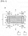
- the fuel cell manufacturing device 100 of the present embodiment comprises coils 101, 102, 103, 104, a plurality of magnetic path forming members 110, a pair of shielding members 120 (pressing fixture), a power source 130 and a control device 140, as illustrated in Figure 1 .
- the coils 101, 102 are disposed on both sides of one of a pair of sites 151 to be heated of the fuel-cell module 150 (laminate) in the stacking direction of a membrane electrode assembly 161 and a pair of separators 162.
- the coils 101, 102 extend in the same direction as the direction that is perpendicular to the stacking direction of the membrane electrode assembly 161 and the separators 162 (the direction perpendicular to the figure in Figure 1 ).
- the coils 103, 104 are also disposed on both sides of one of the sites 151 to be heated in the stacking direction.
- the coils 103, 104 extend in the same direction as the direction that is perpendicular to the stacking direction (the direction perpendicular to the plane in Figure 1 ).
- One of the magnetic path forming members 110 surrounds each of the coils 101, 102, 103, 104.
- An opening 111 is formed in each of the magnetic path forming members 110.
- the openings 111 face the sites 151 to be heated.
- the magnetic path forming members 110 are formed from a ferromagnetic material such as ferrite, magnetic steel sheets, and permalloy.
- the shielding members 120 are disposed in a site 152 in the fuel-cell module 150 that does not require heating (hereinafter referred to as heating-unnecessary site 152).
- the shielding members 120 are formed from a ferromagnetic material. Examples of ferromagnetic materials include ferrite, magnetic steel sheets, and permalloy.
- each of the shielding members 120 is disposed in the sites 151 to be heated.
- the ends 121 are oriented in the stacking direction.
- the shielding members 120 pressurize the fuel-cell module 150 in the stacking direction.
- the shielding members 120 are provided with a pressing force by, for example, an elastic member, such as a spring, so as to pressurize the fuel-cell module 150.
- the pressing force can be provided to the shielding members 120 by fastening the shielding members 120 to each other at the top and bottom.
- the power source 130 is electrically connected to the coils 101, 102, 103, 104.
- the power source 130 passes high-frequency current through the coils 101, 102, 103, 104.
- the power source 130 comprises a frequency regulator that controls the frequency of alternating current, and a transformer to increase or decrease the voltage.
- the control device 140 is electrically connected to the power source 130.
- the control device 140 sends and receives signals to and from the power source 130.
- the control device 140 controls the operation of the power source 130, and controls the electric current that flows through the coils 101, 102, 103, 104.
- the control device 140 is, for example, a computer such as a personal computer or an engineering workstation.
- the fuel-cell module 150 has a configuration obtained by stacking fuel cells 160.
- the fuel cell 160 has a configuration in which a membrane electrode assembly 161 is sandwiched by a pair of separators 162.
- the fuel cell 160 constitutes the minimum unit of a fuel-cell stack.
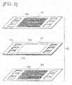
- the membrane electrode assembly 161 comprises an electrolyte membrane 161a, an electrode 161b formed on both surfaces of the electrolyte membrane 161a, and a frame 161 c that is provided around the electrode 161b on both surfaces of the electrolyte membrane 161a, as is illustrated in Figure 2 .
- the electrolyte membrane 161a is a proton conductive ion-exchange membrane formed from a solid polymer material such as fluorine-based resin, and exhibits good electrical conductivity in a wet state.
- the electrode 161b has a configuration in which a gas diffusion layer is formed on a catalyst layer.
- the catalyst layer of the electrode 161b formed on one surface of the electrolyte membrane 161a comprises a catalyst component having a catalytic effect in the reductive reaction of oxygen.
- the catalyst layer of the electrode 161 b formed on the other surface of the electrolyte membrane 161a comprises a catalyst component having a catalytic effect in the oxidative reaction of hydrogen.
- the gas diffusion layer that is provided on the catalyst layer has conductivity and gas diffusibility.
- the gas diffusion layer is formed from, for example, a wire mesh.
- the frame 161c is formed from, for example, resin.
- the separators 162 are formed from a conductive material.
- a conductive material is stainless steel (SUS).
- Other examples of conductive materials include iron, titanium, iron or titanium that contains carbon, and a material consisting of carbon and resin.
- a flow channel 162a is formed on both sides of each of the separators 162. Fuel gas, oxidant gas, or a cooling fluid flows through the flow channels 162a.
- the electrode 161b, the electrolyte membrane 161a between the electrodes 161b, and the flow channels 162a are positioned in the heating-unnecessary site 152.
- the heating-unnecessary site 152 is a power generation reaction portion in which electrochemical reactions proceed.
- the outer perimeter part of the membrane electrode assembly 161 (more specifically, the portion around the electrode 161b), and the outer perimeter part of the separators 162 (more specifically, the portion around the flow channels 162a) correspond to the sites 151 to be heated.
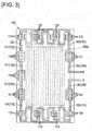
- the coils 101, 102, 103, 104 are disposed on the outer perimeter part of the fuel-cell module 150, which corresponds to the sites 151 to be heated, as is illustrated in Figure 3 .
- the coils 101, 103 are formed from the same wire material.
- the coils 102, 104 are formed from the same wire material.
- the number of magnetic path forming members 110 differs depending on the disposed location. In the example illustrated in Figure 3 , there is a location in which six magnetic path forming members 110 are disposed and a location in which three magnetic path forming members 110 are disposed.
- the saturation magnetic flux density differs depending on the number of magnetic path forming members 110 that are disposed. The saturation magnetic flux density is high in a location where many magnetic path forming members 110 are disposed, and the saturation magnetic flux density is low in a location where the number of magnetic path forming members 110 is small.
- the number and the locations of the magnetic path forming members 110 to be disposed are not particularly limited.
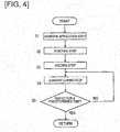
- the fuel cell manufacturing method comprises an adhesive application Step S1 for applying adhesive to a workpiece, a stacking Step S2 for stacking workpieces, a holding Step S3 for holding the stacked workpieces, and an adhesive curing Step S4 for curing the adhesive, as illustrated in Figure 4 .
- an adhesive is applied to the surface of the outer perimeter part of at least one of the membrane electrode assembly 161 and the separators 162, which are stacked and adjacent to each other.
- an adhesive is applied to the surface of the outer perimeter part of at least one of the separators 162 that are adjacent to each other between the fuel cell 160 and the fuel cell 160 when stacked.
- the application of the adhesive may be carried out while a nozzle that discharges the adhesive is moved, or may be carried out by screen printing.
- An example of an adhesive is a thermosetting resin, such as an epoxy resin.
- the separators 162 and the membrane electrode assembly 161 are stacked, and the fuel cell 160 as well as the fuel-cell module 150 are assembled.
- the assembled fuel-cell module 150 is disposed between the shielding members 120 ( Figure 1 ).
- the shielding members 120 pressurize and hold the fuel-cell module 150 in the stacking direction.
- Magnetic flux M is formed in the sites 151 to be heated, so as to be substantially perpendicular to the surfaces of the separators 162.
- induction current is generated in a location of each of the separators 162 that corresponds to the sites 151 to be heated, and heat that corresponds to the induction current is generated.
- the adhesive is cured by this heat, bonding the stacked members to each other.
- the control device 140 stops the current that flows in the coils 101, 102, 103, 104 after a predetermined time has elapsed and ends the heating (S5 in Figure 4 ).
- the completed fuel-cell module 150 is tested for gas leaks, power generation performance, and the like. Thereafter, a fuel cell stack is formed by stacking and fastening a multiplicity of fuel-cell modules 150. The fuel cell stack is also tested for gas leaks, power generation performance, and the like.
- electric current is passed through the coils 101, 102 (coils 103, 104), which are disposed on both sides of the sites 151 to be heated in the stacking direction, in the same direction as directions intersecting the stacking direction.
- magnetic flux M is selectively generated in the sites 151 to be heated, in a direction that is substantially perpendicular to the surfaces of the separators 162, and induction current is selectively generated in the separators 162 in locations that correspond to the sites 151 to be heated. Therefore, it is possible to heat the sites 151 to be heated in a localized manner.
- the Shielding members 120 are disposed in the heating-unnecessary site 152, the magnetic flux density that penetrates the heating-unnecessary site 152 is reduced. As a result, the induction current is reduced, and the generation of heat at the heating-unnecessary site 152 is suppressed.
- the ends 121 of the shielding members 120 which are formed from a ferromagnetic material, are located in the sites 151 to be heated, and are oriented in the stacking direction.
- the magnetic flux M is thereby induced at the sites 151 to be heated and easily converges. Accordingly, the magnetic flux density that is substantially perpendicular to the surfaces of the separators 162 is increased at the sites 151 to be heated, and, as a result, the induction current is increased, and the amount of generated heat at the sites 151 to be heated is increased. Therefore, it is possible to efficiently carry out localized induction heating of the sites 151 to be heated.
- the magnetic path forming members. 110 are disposed such that the openings 111 face the sites 151 to be heated.
- the magnetic flux M is thereby induced at the sites 151 to be heated and easily converges, and the magnetic flux density that is substantially perpendicular to the surfaces of the separators 162 is increased.
- the induction current is increased and the amount of generated heat at the sites 151 to be heated is increased; it is thereby possible to efficiently heat the sites 151 to be heated.
- the number of the magnetic path forming members 110 differs depending on the disposed location (refer to Figure 3 ), and, as a result, the saturation magnetic flux density changes depending on the location. Accordingly, it is possible to change the amount of generated heat depending on the location, and to carry out heating that is appropriate to that location. For example, a large number of magnetic path forming members 110 are disposed in a location for which heating to a relatively high temperature is desired in order to increase the amount of generated heat, and, conversely, the magnetic path forming members 110 are reduced in in number, or not disposed at all, in a location where it is desired to suppress the temperature, in order to suppress the amount of generated heat.
- the sites 151 to be heated is heated in a state of pressurization by the shielding members 120; therefore, the stacked members are attached to each other and bonded together. Therefore, the electrical conductivity between the members becomes excellent.
- the shielding members 120 play the role of a pressing fixture that pressurizes the fuel-cell module 150, it is not necessary to separately provide pressing fixtures; therefore, the device can be simplified.
- the fuel-cell module 150 is heated in the embodiment described above, but no limitation is thereby implied; one fuel cell 160 as a laminate may be heated.
- the present invention includes a fuel cell manufacturing device 200 in which the magnetic path forming members 110 and the shielding members 120 are omitted from the embodiment described above, as illustrated in Figure 6 .
- the other configurations of the fuel cell manufacturing device 200 are the same as the above-described embodiment, which are given the same codes as the fuel cell manufacturing device 100.
- the fuel cell manufacturing device 200 is also capable of heating the sites 151 to be heated in a localized manner by magnetic flux M that is generated by the coils 101, 102 (coils 103, 104),
- the present invention includes an embodiment in which one of the magnetic path forming members 110 or the shielding members 120 of the above-described embodiment is added to the fuel cell manufacturing device 200.
- the shielding members are not limited to the shielding members 120 of the above-described embodiment.
- the present invention includes a fuel cell manufacturing device 300 that has a pair of shielding members 320 that are different from the embodiment described above, as illustrated in Figure 7 .
- the other configurations of the fuel cell manufacturing device 300 are the same as the fuel cell manufacturing device 200.
- the ends 321 of the shielding members 320 are located in the sites 151 to be heated, but is not oriented in the stacking direction as is the case with the ends 121 of the shielding members 120 of the above-described embodiment; rather, the ends are oriented in a direction along the surface of the stacked members.
- the shielding members 320 are formed from a ferromagnetic material.
- the shielding members are not limited to the Shielding members 120, 320 that are formed from a ferromagnetic material, and include a shielding member that are formed from a non-magnetic metal body.
- the shielding members 420 illustrated in Figure 8 are formed from a non-magnetic metal body, and has different thicknesses.
- the thicknesses of the shielding members 420 are relatively thick at the heating-unnecessary site 152, and the thicknesses are relatively thin at ends 421 are is disposed in the sites 151 to be heated.
- Examples of a non-magnetic metal body that form each of the shielding members 420 include aluminum, copper, and austenitic SUS.
- the configurations of the fuel cell manufacturing device 400 other than the shielding members 420 are the same as the fuel cell manufacturing device 300.
- the shielding members 120 and the shielding members 320 which are formed from a ferromagnetic material (refer to Figure 5 and Figure 7 ), conduct shielding by inducing the magnetic flux M so as to avoid the heating-unnecessary site 152.
- a ferromagnetic material (refer to Figure 5 and Figure 7 )
- magnetic flux that cancels out this high-frequency magnetic flux is generated in the shielding members 420 that are formed from a non-magnetic metal body, and the high-frequency magnetic flux is thereby shielded.
- the induction current that generates the magnetic flux that cancels out the high-frequency magnetic flux will vary according to the electrical resistance. Since the shielding members 420 has different thicknesses and the electrical resistance differs depending on the site, the shielding effect also differs depending on the site.
- the electrical resistance is low in a thick location disposed in the heating-unnecessary site 152. Accordingly, when a high-frequency magnetic flux acts, the magnetic flux that cancels out the high-frequency magnetic flux is increased. Therefore, the shielding effect is high.
- the electrical resistance is high in the thin locations 421 disposed in the sites 151 to be heated. Accordingly, when high-frequency magnetic flux acts, the magnetic flux that cancels out the high-frequency magnetic flux is small. Therefore, the shielding effect is low.
- the shielding members 420 are formed from a non-magnetic metal body and has differing thicknesses, and the shielding effect against magnetic flux is thereby adjusted. Accordingly, the shielding members 420 are capable of controlling the distribution of the generated heat of the fuel-cell module 150 according to the magnitude of the thickness.
- a temperature sensor such as a thermocouple may be provided to the shielding members 120, 320, 420. If the control device 140 controls the electric current of the coils 101, 102, 103, 104 based on the temperature that is detected by the temperature sensor, it is possible to more appropriately adjust the heating temperature.
- the number of the magnetic path forming members 110 differs as a function of the disposed location, as illustrated in Figure 3 , and the saturation magnetic flux density is thereby varied; however, the method to vary the saturation magnetic flux density according to location is not limited in this way.
- the saturation magnetic flux density may be varied by changing the material or the volume material, or changing at least two from among the disposed number, the material, and the volume, of the magnetic path forming members 110, depending on the disposed location of the magnetic path forming members 110. Furthermore, the saturation magnetic flux density may be varied by changing the ratio (W/G) of the gap G between the magnetic path forming members 110 in the stacking direction illustrated in Figure 1 and the opening W depending on the disposed location of the magnetic path forming members 110.
- the present invention includes a fuel cell manufacturing device 500 in which non-magnetic metal plates 570 are disposed between shielding members 520 and the fuel-cell module 150 (laminate), as illustrated in Figure 9 .
- the fuel cell manufacturing device 500 comprises the coils 101, 102, 103, 104, the magnetic path forming members 110, the power source 130 and the control device 140.
- the coils 101-104, the magnetic path forming members 110, the power source 130, the control device 140, and the fuel-cell module 150 are substantially the same as in the above-described embodiment, so that the same reference numerals are provided in the drawings, and the associated explanations are omitted here.
- the shielding members 520 ae disposed in the heating-unnecessary sites 152 with the metal plates 570 interposed therebetween, and shields the magnetic flux from the coils 101-104.
- the material that forms the shielding members 520 is the same as the shielding members 120 of the above-described embodiment.
- the shielding members 520 have a smooth plate shape with a substantially constant thickness. The shielding members 520 pressurize the fuel-cell module 150 in the stacking direction.
- the shielding members 520 have substantially the same width as the heating-unnecessary site 152 in the planar direction. The ends of the shielding members 520 isare positioned further on the heating-unnecessary site 152 side than the sites 151 to be heated in the planar direction, and are not between the sites 151 to be heated and the magnetic path forming members 110.
- the metal plates 570 are disposed between the shielding member 520 and the heating-unnecessary site 152, are extended in the planar direction, and disposed at the sites 151 to be heated. Examples of materials that form the metal plates 570 include aluminum, copper, and austenitic SUS.
- heating-unnecessary site 152 heat generation is suppressed more compared to the sites 151 to be heated; however, when there is variation in the heat generating conditions in the stacking direction and the planar direction, it is conceivable that a portion of the heating-unnecessary site 152 becomes locally higher in temperature than the other portions.
- the metal plates 570 extend between the shielding members 520 and the heating-unnecessary site 152, and the heat generating conditions in the stacking direction and the planar direction are thereby made uniform in the heating-unnecessary site 152; therefore, it is possible to suppress the overall heat generation in the heating-unnecessary site 152 in a substantially uniform manner.
- the sites 151 to be heated generates heat at a relatively higher temperature than the heating-unnecessary site 152; however, when there is variation in the heat generating conditions in the stacking direction and the planar direction, it is conceivable that heat generation is suppressed in a portion of the sites 151 to be heated, or that a portion of the sites 151 to be heated will generate heat greater than or equal to a predetermined temperature.
- a metal plate 570 that extends in the planar direction is disposed in the sites 151 to be heated, and the heat generation conditions in the stacking direction and the planar direction are thereby made uniform in the sites 151 to be hated; therefore, it is possible to generate heat in the sites 151 to be heated over the entirety thereof in a substantially uniform manner.
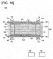
- the present invention includes a fuel cell manufacturing device 600 that pressurizes the fuel-cell module (laminate) with a pressing fixture 580 provided with a pair of non-conductive member 581 and a pair of fastening members 582, as is illustrated in Figure 10 .
- the fuel cell manufacturing device 600 is different from the aforementioned fuel cell manufacturing device 500 in that the pressing fixture 580 is included but is otherwise the same as the fuel cell manufacturing device 500 in other configurations; therefore, the same reference numerals are provided in the drawings, and redundant explanations are omitted.
- the non-conductive members 581 haves a smooth plate shape with a substantially constant thickness.
- the non-conductive members 581 are formed from, for example, resin.
- the non-conductive members 581 are disposed on both sides of the fuel-cell module 150 in the stacking direction and sandwiches same.
- the non-conductive members 581 are disposed between the shielding members 520 and the metal plates 570.
- the non-conductive members 581 are disposed in the site to be heated 512, is extended in the planar direction, and disposed in the sites 151 to be heated. In addition, the non-conductive members 581 protrude from the edge of the fuel-cell module 150 in the planar direction.
- the fastening members 582 each comprises a shaft-like member, on the outer perimeter of which is formed a screw groove, and a nut that is screwed to this shaft-like member.
- the fastening members 582 fasten the non-conductive members 581 to each other, by inserting the shaft-like member on which is formed a screw groove into the non-conductive member 581 and fastening same with a nut.
- the present modified example is configured to pressurize the fuel-cell module 150 with the non-conductive members 581; it is thereby possible to pressurize the sites 151 to be heated through which magnetic flux passes, and to cure the adhesive in a state in which members are placed more closely in contact with each other, and therefore it is possible to more firmly bond the members together.
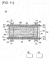
- the present invention includes a fuel cell manufacturing device 700 in which the non-conductive members 581 and the metal plates 770 are integrally formed, as is illustrated in Figure 11 .
- the fuel cell manufacturing device 700 is different from the aforementioned fuel cell manufacturing device 600 in that the non-conductive members 581 and the metal plates 770 are integrally formed, but is otherwise the same as the fuel cell manufacturing device 600 in other configurations; therefore, the same reference numerals are provided in the drawings, and redundant explanations are omitted.
- the metal plates 770 protrude from the edge of the fuel-cell module 150 in the planar direction, but other configurations thereof, such as the material that forms the metal plates 770, are the same as the metal plates 570.
- the pressing fixtures 780 of the present modified example include the metal plates 770, and pressurizes the fuel-cell module 150 by fastening the integrally formed metal plates 770 and the non-conductive members 581 with the fastening members 582.
- the metal plates 770 and the non-conductive members 581 are integrally formed and used for pressurizing the fuel-cell module 150, and the non-conductive members 581 are reinforced by the metal plates 770; therefore, it is possible to improve the durability of the non-conductive members 581.
Landscapes
- Life Sciences & Earth Sciences (AREA)
- Engineering & Computer Science (AREA)
- Manufacturing & Machinery (AREA)
- Sustainable Development (AREA)
- Sustainable Energy (AREA)
- Chemical & Material Sciences (AREA)
- Chemical Kinetics & Catalysis (AREA)
- Electrochemistry (AREA)
- General Chemical & Material Sciences (AREA)
- Physics & Mathematics (AREA)
- Electromagnetism (AREA)
- Fuel Cell (AREA)
Applications Claiming Priority (2)
| Application Number | Priority Date | Filing Date | Title |
|---|---|---|---|
| PCT/JP2014/063503 WO2015177892A1 (ja) | 2014-05-21 | 2014-05-21 | 燃料電池の製造方法および燃料電池の製造装置 |
| PCT/JP2015/064536 WO2015178432A1 (ja) | 2014-05-21 | 2015-05-20 | 燃料電池の製造方法および燃料電池の製造装置 |
Publications (3)
| Publication Number | Publication Date |
|---|---|
| EP3147983A4 EP3147983A4 (de) | 2017-03-29 |
| EP3147983A1 true EP3147983A1 (de) | 2017-03-29 |
| EP3147983B1 EP3147983B1 (de) | 2018-07-04 |
Family
ID=54553588
Family Applications (1)
| Application Number | Title | Priority Date | Filing Date |
|---|---|---|---|
| EP15795720.0A Not-in-force EP3147983B1 (de) | 2014-05-21 | 2015-05-20 | Verfahren zur herstellung einer brennstoffzelle und vorrichtung zur herstellung einer brennstoffzelle |
Country Status (6)
| Country | Link |
|---|---|
| US (1) | US10128524B2 (de) |
| EP (1) | EP3147983B1 (de) |
| JP (1) | JP6288256B2 (de) |
| CN (1) | CN106463757A (de) |
| CA (1) | CA2949769C (de) |
| WO (2) | WO2015177892A1 (de) |
Cited By (3)
| Publication number | Priority date | Publication date | Assignee | Title |
|---|---|---|---|---|
| WO2023072942A2 (de) | 2021-10-29 | 2023-05-04 | Volkswagen Aktiengesellschaft | Verfahren und vorrichtung zum laminieren von komponenten einer batteriezelle |
| DE102023122177A1 (de) | 2023-08-18 | 2025-02-20 | Friedrich-Alexander-Universität Erlangen-Nürnberg, Körperschaft des öffentlichen Rechts | Vorrichtung und Verfahren zur Herstellung eines Folienverbunds |
| DE102023135183A1 (de) * | 2023-12-14 | 2025-06-18 | Friedrich-Alexander-Universität Erlangen-Nürnberg, in Vertretung des Freistaates Bayern | Vorrichtung und Verfahren zur Herstellung eines Folienverbunds |
Families Citing this family (5)
| Publication number | Priority date | Publication date | Assignee | Title |
|---|---|---|---|---|
| JP6349961B2 (ja) * | 2014-05-26 | 2018-07-04 | 日産自動車株式会社 | 樹脂フレーム付き膜電極接合体の製造装置および製造方法 |
| JP7064113B2 (ja) * | 2017-03-06 | 2022-05-10 | 東洋インキScホールディングス株式会社 | 燃料電池用セルの製造方法 |
| JP6812945B2 (ja) * | 2017-10-18 | 2021-01-13 | トヨタ自動車株式会社 | 燃料電池用セパレータの製造方法 |
| JP6926999B2 (ja) * | 2017-12-05 | 2021-08-25 | トヨタ自動車株式会社 | 燃料電池セルの製造方法 |
| JP7031486B2 (ja) * | 2018-05-14 | 2022-03-08 | トヨタ自動車株式会社 | 燃料電池セパレータの表面処理方法及び表面処理装置 |
Family Cites Families (13)
| Publication number | Priority date | Publication date | Assignee | Title |
|---|---|---|---|---|
| GB1546367A (en) * | 1975-03-10 | 1979-05-23 | Electricity Council | Induction heating of strip and other elongate metal workpieces |
| JPS577082A (en) * | 1980-06-13 | 1982-01-14 | Riccar Sewing Machine Kk | Exciter for induction heater |
| US4561489A (en) * | 1982-03-25 | 1985-12-31 | Olin Corporation | Flux concentrator |
| JP2594332B2 (ja) * | 1987-09-02 | 1997-03-26 | 富士電機株式会社 | ダイスの誘導加熱装置 |
| JP3741768B2 (ja) * | 1996-02-07 | 2006-02-01 | 北芝電機株式会社 | 誘導加熱装置 |
| JP3596585B2 (ja) * | 1997-12-25 | 2004-12-02 | 三菱自動車工業株式会社 | 板金ワークのプリキュア装置 |
| FR2808163B1 (fr) | 2000-04-19 | 2002-11-08 | Celes | Dispositif de chauffage par induction a flux transverse a circuit magnetique de largeur variable |
| US20050061804A1 (en) * | 2003-09-22 | 2005-03-24 | Norman Golm | Induction flux concentrator utilized for forming heat exchangers |
| JP4411968B2 (ja) * | 2003-12-26 | 2010-02-10 | トヨタ自動車株式会社 | 燃料電池解体方法及び燃料電池 |
| JP2006134644A (ja) * | 2004-11-04 | 2006-05-25 | Nissan Motor Co Ltd | 燃料電池組み立て方法 |
| JP4835029B2 (ja) * | 2005-04-22 | 2011-12-14 | トヨタ自動車株式会社 | 燃料電池の製造方法 |
| JP5063755B2 (ja) * | 2010-08-09 | 2012-10-31 | 三井造船株式会社 | 誘導加熱装置および誘導加熱方法 |
| JP2013187036A (ja) * | 2012-03-08 | 2013-09-19 | Toyota Motor Corp | 燃料電池用部材の製造装置及び燃料電池用部材の製造方法 |
-
2014
- 2014-05-21 WO PCT/JP2014/063503 patent/WO2015177892A1/ja not_active Ceased
-
2015
- 2015-05-20 JP JP2016521138A patent/JP6288256B2/ja not_active Expired - Fee Related
- 2015-05-20 CA CA2949769A patent/CA2949769C/en not_active Expired - Fee Related
- 2015-05-20 WO PCT/JP2015/064536 patent/WO2015178432A1/ja not_active Ceased
- 2015-05-20 CN CN201580025638.3A patent/CN106463757A/zh active Pending
- 2015-05-20 US US15/308,390 patent/US10128524B2/en not_active Expired - Fee Related
- 2015-05-20 EP EP15795720.0A patent/EP3147983B1/de not_active Not-in-force
Cited By (5)
| Publication number | Priority date | Publication date | Assignee | Title |
|---|---|---|---|---|
| WO2023072942A2 (de) | 2021-10-29 | 2023-05-04 | Volkswagen Aktiengesellschaft | Verfahren und vorrichtung zum laminieren von komponenten einer batteriezelle |
| DE102021128348A1 (de) | 2021-10-29 | 2023-05-04 | Volkswagen Aktiengesellschaft | Verfahren und Vorrichung zum Laminieren von Komponenten einer Batteriezelle |
| WO2023072942A3 (de) * | 2021-10-29 | 2023-07-27 | Volkswagen Aktiengesellschaft | Verfahren und vorrichtung zum laminieren von komponenten einer batteriezelle |
| DE102023122177A1 (de) | 2023-08-18 | 2025-02-20 | Friedrich-Alexander-Universität Erlangen-Nürnberg, Körperschaft des öffentlichen Rechts | Vorrichtung und Verfahren zur Herstellung eines Folienverbunds |
| DE102023135183A1 (de) * | 2023-12-14 | 2025-06-18 | Friedrich-Alexander-Universität Erlangen-Nürnberg, in Vertretung des Freistaates Bayern | Vorrichtung und Verfahren zur Herstellung eines Folienverbunds |
Also Published As
| Publication number | Publication date |
|---|---|
| US10128524B2 (en) | 2018-11-13 |
| CA2949769A1 (en) | 2015-11-26 |
| WO2015178432A1 (ja) | 2015-11-26 |
| JP6288256B2 (ja) | 2018-03-07 |
| CN106463757A (zh) | 2017-02-22 |
| JPWO2015178432A1 (ja) | 2017-04-20 |
| EP3147983B1 (de) | 2018-07-04 |
| WO2015177892A1 (ja) | 2015-11-26 |
| US20170069928A1 (en) | 2017-03-09 |
| EP3147983A4 (de) | 2017-03-29 |
| CA2949769C (en) | 2017-12-12 |
Similar Documents
| Publication | Publication Date | Title |
|---|---|---|
| CA2949769C (en) | Manufacturing method of fuel cell and manufacturing device of fuel cell | |
| CA2910082C (en) | Insulating structure, fuel cell and fuel cell stack | |
| CA2776455C (en) | Polymer electrolyte membrane fuel cell assembly | |
| CN105210224A (zh) | 燃料电池的制造方法和制造装置 | |
| CN110140422B (zh) | 电加热器及其制造方法 | |
| JP2007296553A (ja) | 薄板の電磁成形装置 | |
| JP2010103071A (ja) | 電流測定装置 | |
| CN105229835B (zh) | 燃料电池用的分隔件组件的制造装置和制造方法 | |
| CN105210221B (zh) | 燃料电池用分隔件的制造方法和制造装置 | |
| JP2013187036A (ja) | 燃料電池用部材の製造装置及び燃料電池用部材の製造方法 | |
| JP5141281B2 (ja) | 燃料電池用電極集成体の製造方法 | |
| JP4835029B2 (ja) | 燃料電池の製造方法 | |
| JP2018531209A6 (ja) | フォースコンセントレーターパターンを有するバイポーラプレート | |
| JP4911951B2 (ja) | 燃料電池及びその製造方法 | |
| JP2019139993A (ja) | 燃料電池モジュールおよびその製造方法 | |
| JP2012152821A (ja) | 電磁溶接用平板状ワンターンコイル | |
| JP2006134644A (ja) | 燃料電池組み立て方法 | |
| JP2008041448A (ja) | 燃料電池用セパレータ、燃料電池および燃料電池の製造方法 | |
| JP2016131088A (ja) | 燃料電池 | |
| JP5664435B2 (ja) | 電流測定装置 | |
| JP2023119311A (ja) | 燃料電池及びその製造方法 | |
| JP2024030908A (ja) | 燃料電池用接着剤 | |
| JP2007299673A (ja) | 燃料電池スタック |
Legal Events
| Date | Code | Title | Description |
|---|---|---|---|
| STAA | Information on the status of an ep patent application or granted ep patent |
Free format text: STATUS: THE INTERNATIONAL PUBLICATION HAS BEEN MADE |
|
| PUAI | Public reference made under article 153(3) epc to a published international application that has entered the european phase |
Free format text: ORIGINAL CODE: 0009012 |
|
| STAA | Information on the status of an ep patent application or granted ep patent |
Free format text: STATUS: REQUEST FOR EXAMINATION WAS MADE |
|
| 17P | Request for examination filed |
Effective date: 20161221 |
|
| A4 | Supplementary search report drawn up and despatched |
Effective date: 20170213 |
|
| AK | Designated contracting states |
Kind code of ref document: A1 Designated state(s): AL AT BE BG CH CY CZ DE DK EE ES FI FR GB GR HR HU IE IS IT LI LT LU LV MC MK MT NL NO PL PT RO RS SE SI SK SM TR |
|
| AX | Request for extension of the european patent |
Extension state: BA ME |
|
| DAV | Request for validation of the european patent (deleted) | ||
| DAX | Request for extension of the european patent (deleted) | ||
| RIC1 | Information provided on ipc code assigned before grant |
Ipc: H05B 6/36 20060101ALI20171127BHEP Ipc: H01M 8/1004 20160101ALI20171127BHEP Ipc: H01M 8/10 20160101ALI20171127BHEP Ipc: B32B 37/06 20060101ALI20171127BHEP Ipc: H01M 8/24 20160101AFI20171127BHEP Ipc: B32B 37/12 20060101ALI20171127BHEP Ipc: H01M 8/0286 20160101ALI20171127BHEP Ipc: H05B 6/10 20060101ALI20171127BHEP Ipc: B32B 7/14 20060101ALI20171127BHEP Ipc: B32B 37/00 20060101ALI20171127BHEP |
|
| GRAP | Despatch of communication of intention to grant a patent |
Free format text: ORIGINAL CODE: EPIDOSNIGR1 |
|
| STAA | Information on the status of an ep patent application or granted ep patent |
Free format text: STATUS: GRANT OF PATENT IS INTENDED |
|
| INTG | Intention to grant announced |
Effective date: 20180105 |
|
| GRAS | Grant fee paid |
Free format text: ORIGINAL CODE: EPIDOSNIGR3 |
|
| GRAA | (expected) grant |
Free format text: ORIGINAL CODE: 0009210 |
|
| STAA | Information on the status of an ep patent application or granted ep patent |
Free format text: STATUS: THE PATENT HAS BEEN GRANTED |
|
| AK | Designated contracting states |
Kind code of ref document: B1 Designated state(s): AL AT BE BG CH CY CZ DE DK EE ES FI FR GB GR HR HU IE IS IT LI LT LU LV MC MK MT NL NO PL PT RO RS SE SI SK SM TR |
|
| REG | Reference to a national code |
Ref country code: GB Ref legal event code: FG4D |
|
| REG | Reference to a national code |
Ref country code: CH Ref legal event code: EP |
|
| REG | Reference to a national code |
Ref country code: AT Ref legal event code: REF Ref document number: 1015479 Country of ref document: AT Kind code of ref document: T Effective date: 20180715 |
|
| REG | Reference to a national code |
Ref country code: IE Ref legal event code: FG4D |
|
| REG | Reference to a national code |
Ref country code: DE Ref legal event code: R096 Ref document number: 602015013176 Country of ref document: DE |
|
| REG | Reference to a national code |
Ref country code: NL Ref legal event code: MP Effective date: 20180704 |
|
| REG | Reference to a national code |
Ref country code: LT Ref legal event code: MG4D |
|
| REG | Reference to a national code |
Ref country code: AT Ref legal event code: MK05 Ref document number: 1015479 Country of ref document: AT Kind code of ref document: T Effective date: 20180704 |
|
| PG25 | Lapsed in a contracting state [announced via postgrant information from national office to epo] |
Ref country code: NL Free format text: LAPSE BECAUSE OF FAILURE TO SUBMIT A TRANSLATION OF THE DESCRIPTION OR TO PAY THE FEE WITHIN THE PRESCRIBED TIME-LIMIT Effective date: 20180704 |
|
| PG25 | Lapsed in a contracting state [announced via postgrant information from national office to epo] |
Ref country code: CZ Free format text: LAPSE BECAUSE OF FAILURE TO SUBMIT A TRANSLATION OF THE DESCRIPTION OR TO PAY THE FEE WITHIN THE PRESCRIBED TIME-LIMIT Effective date: 20180704 Ref country code: PL Free format text: LAPSE BECAUSE OF FAILURE TO SUBMIT A TRANSLATION OF THE DESCRIPTION OR TO PAY THE FEE WITHIN THE PRESCRIBED TIME-LIMIT Effective date: 20180704 Ref country code: LT Free format text: LAPSE BECAUSE OF FAILURE TO SUBMIT A TRANSLATION OF THE DESCRIPTION OR TO PAY THE FEE WITHIN THE PRESCRIBED TIME-LIMIT Effective date: 20180704 Ref country code: BG Free format text: LAPSE BECAUSE OF FAILURE TO SUBMIT A TRANSLATION OF THE DESCRIPTION OR TO PAY THE FEE WITHIN THE PRESCRIBED TIME-LIMIT Effective date: 20181004 Ref country code: SE Free format text: LAPSE BECAUSE OF FAILURE TO SUBMIT A TRANSLATION OF THE DESCRIPTION OR TO PAY THE FEE WITHIN THE PRESCRIBED TIME-LIMIT Effective date: 20180704 Ref country code: NO Free format text: LAPSE BECAUSE OF FAILURE TO SUBMIT A TRANSLATION OF THE DESCRIPTION OR TO PAY THE FEE WITHIN THE PRESCRIBED TIME-LIMIT Effective date: 20181004 Ref country code: AT Free format text: LAPSE BECAUSE OF FAILURE TO SUBMIT A TRANSLATION OF THE DESCRIPTION OR TO PAY THE FEE WITHIN THE PRESCRIBED TIME-LIMIT Effective date: 20180704 Ref country code: FI Free format text: LAPSE BECAUSE OF FAILURE TO SUBMIT A TRANSLATION OF THE DESCRIPTION OR TO PAY THE FEE WITHIN THE PRESCRIBED TIME-LIMIT Effective date: 20180704 Ref country code: IS Free format text: LAPSE BECAUSE OF FAILURE TO SUBMIT A TRANSLATION OF THE DESCRIPTION OR TO PAY THE FEE WITHIN THE PRESCRIBED TIME-LIMIT Effective date: 20181104 Ref country code: GR Free format text: LAPSE BECAUSE OF FAILURE TO SUBMIT A TRANSLATION OF THE DESCRIPTION OR TO PAY THE FEE WITHIN THE PRESCRIBED TIME-LIMIT Effective date: 20181005 Ref country code: RS Free format text: LAPSE BECAUSE OF FAILURE TO SUBMIT A TRANSLATION OF THE DESCRIPTION OR TO PAY THE FEE WITHIN THE PRESCRIBED TIME-LIMIT Effective date: 20180704 |
|
| PG25 | Lapsed in a contracting state [announced via postgrant information from national office to epo] |
Ref country code: LV Free format text: LAPSE BECAUSE OF FAILURE TO SUBMIT A TRANSLATION OF THE DESCRIPTION OR TO PAY THE FEE WITHIN THE PRESCRIBED TIME-LIMIT Effective date: 20180704 Ref country code: ES Free format text: LAPSE BECAUSE OF FAILURE TO SUBMIT A TRANSLATION OF THE DESCRIPTION OR TO PAY THE FEE WITHIN THE PRESCRIBED TIME-LIMIT Effective date: 20180704 Ref country code: HR Free format text: LAPSE BECAUSE OF FAILURE TO SUBMIT A TRANSLATION OF THE DESCRIPTION OR TO PAY THE FEE WITHIN THE PRESCRIBED TIME-LIMIT Effective date: 20180704 Ref country code: AL Free format text: LAPSE BECAUSE OF FAILURE TO SUBMIT A TRANSLATION OF THE DESCRIPTION OR TO PAY THE FEE WITHIN THE PRESCRIBED TIME-LIMIT Effective date: 20180704 |
|
| REG | Reference to a national code |
Ref country code: DE Ref legal event code: R097 Ref document number: 602015013176 Country of ref document: DE |
|
| PG25 | Lapsed in a contracting state [announced via postgrant information from national office to epo] |
Ref country code: EE Free format text: LAPSE BECAUSE OF FAILURE TO SUBMIT A TRANSLATION OF THE DESCRIPTION OR TO PAY THE FEE WITHIN THE PRESCRIBED TIME-LIMIT Effective date: 20180704 Ref country code: IT Free format text: LAPSE BECAUSE OF FAILURE TO SUBMIT A TRANSLATION OF THE DESCRIPTION OR TO PAY THE FEE WITHIN THE PRESCRIBED TIME-LIMIT Effective date: 20180704 Ref country code: RO Free format text: LAPSE BECAUSE OF FAILURE TO SUBMIT A TRANSLATION OF THE DESCRIPTION OR TO PAY THE FEE WITHIN THE PRESCRIBED TIME-LIMIT Effective date: 20180704 |
|
| PLBE | No opposition filed within time limit |
Free format text: ORIGINAL CODE: 0009261 |
|
| STAA | Information on the status of an ep patent application or granted ep patent |
Free format text: STATUS: NO OPPOSITION FILED WITHIN TIME LIMIT |
|
| PG25 | Lapsed in a contracting state [announced via postgrant information from national office to epo] |
Ref country code: SK Free format text: LAPSE BECAUSE OF FAILURE TO SUBMIT A TRANSLATION OF THE DESCRIPTION OR TO PAY THE FEE WITHIN THE PRESCRIBED TIME-LIMIT Effective date: 20180704 Ref country code: SM Free format text: LAPSE BECAUSE OF FAILURE TO SUBMIT A TRANSLATION OF THE DESCRIPTION OR TO PAY THE FEE WITHIN THE PRESCRIBED TIME-LIMIT Effective date: 20180704 Ref country code: DK Free format text: LAPSE BECAUSE OF FAILURE TO SUBMIT A TRANSLATION OF THE DESCRIPTION OR TO PAY THE FEE WITHIN THE PRESCRIBED TIME-LIMIT Effective date: 20180704 |
|
| 26N | No opposition filed |
Effective date: 20190405 |
|
| PG25 | Lapsed in a contracting state [announced via postgrant information from national office to epo] |
Ref country code: SI Free format text: LAPSE BECAUSE OF FAILURE TO SUBMIT A TRANSLATION OF THE DESCRIPTION OR TO PAY THE FEE WITHIN THE PRESCRIBED TIME-LIMIT Effective date: 20180704 |
|
| REG | Reference to a national code |
Ref country code: CH Ref legal event code: PL |
|
| PG25 | Lapsed in a contracting state [announced via postgrant information from national office to epo] |
Ref country code: CH Free format text: LAPSE BECAUSE OF NON-PAYMENT OF DUE FEES Effective date: 20190531 Ref country code: MC Free format text: LAPSE BECAUSE OF FAILURE TO SUBMIT A TRANSLATION OF THE DESCRIPTION OR TO PAY THE FEE WITHIN THE PRESCRIBED TIME-LIMIT Effective date: 20180704 Ref country code: LI Free format text: LAPSE BECAUSE OF NON-PAYMENT OF DUE FEES Effective date: 20190531 |
|
| REG | Reference to a national code |
Ref country code: BE Ref legal event code: MM Effective date: 20190531 |
|
| PG25 | Lapsed in a contracting state [announced via postgrant information from national office to epo] |
Ref country code: LU Free format text: LAPSE BECAUSE OF NON-PAYMENT OF DUE FEES Effective date: 20190520 |
|
| PG25 | Lapsed in a contracting state [announced via postgrant information from national office to epo] |
Ref country code: TR Free format text: LAPSE BECAUSE OF FAILURE TO SUBMIT A TRANSLATION OF THE DESCRIPTION OR TO PAY THE FEE WITHIN THE PRESCRIBED TIME-LIMIT Effective date: 20180704 |
|
| PG25 | Lapsed in a contracting state [announced via postgrant information from national office to epo] |
Ref country code: IE Free format text: LAPSE BECAUSE OF NON-PAYMENT OF DUE FEES Effective date: 20190520 |
|
| PG25 | Lapsed in a contracting state [announced via postgrant information from national office to epo] |
Ref country code: BE Free format text: LAPSE BECAUSE OF NON-PAYMENT OF DUE FEES Effective date: 20190531 |
|
| PG25 | Lapsed in a contracting state [announced via postgrant information from national office to epo] |
Ref country code: PT Free format text: LAPSE BECAUSE OF FAILURE TO SUBMIT A TRANSLATION OF THE DESCRIPTION OR TO PAY THE FEE WITHIN THE PRESCRIBED TIME-LIMIT Effective date: 20181104 |
|
| PGFP | Annual fee paid to national office [announced via postgrant information from national office to epo] |
Ref country code: DE Payment date: 20200506 Year of fee payment: 6 Ref country code: FR Payment date: 20200414 Year of fee payment: 6 |
|
| PGFP | Annual fee paid to national office [announced via postgrant information from national office to epo] |
Ref country code: GB Payment date: 20200513 Year of fee payment: 6 |
|
| PG25 | Lapsed in a contracting state [announced via postgrant information from national office to epo] |
Ref country code: CY Free format text: LAPSE BECAUSE OF FAILURE TO SUBMIT A TRANSLATION OF THE DESCRIPTION OR TO PAY THE FEE WITHIN THE PRESCRIBED TIME-LIMIT Effective date: 20180704 |
|
| PG25 | Lapsed in a contracting state [announced via postgrant information from national office to epo] |
Ref country code: HU Free format text: LAPSE BECAUSE OF FAILURE TO SUBMIT A TRANSLATION OF THE DESCRIPTION OR TO PAY THE FEE WITHIN THE PRESCRIBED TIME-LIMIT; INVALID AB INITIO Effective date: 20150520 Ref country code: MT Free format text: LAPSE BECAUSE OF FAILURE TO SUBMIT A TRANSLATION OF THE DESCRIPTION OR TO PAY THE FEE WITHIN THE PRESCRIBED TIME-LIMIT Effective date: 20180704 |
|
| REG | Reference to a national code |
Ref country code: DE Ref legal event code: R119 Ref document number: 602015013176 Country of ref document: DE |
|
| GBPC | Gb: european patent ceased through non-payment of renewal fee |
Effective date: 20210520 |
|
| PG25 | Lapsed in a contracting state [announced via postgrant information from national office to epo] |
Ref country code: GB Free format text: LAPSE BECAUSE OF NON-PAYMENT OF DUE FEES Effective date: 20210520 Ref country code: DE Free format text: LAPSE BECAUSE OF NON-PAYMENT OF DUE FEES Effective date: 20211201 |
|
| PG25 | Lapsed in a contracting state [announced via postgrant information from national office to epo] |
Ref country code: FR Free format text: LAPSE BECAUSE OF NON-PAYMENT OF DUE FEES Effective date: 20210531 |
|
| PG25 | Lapsed in a contracting state [announced via postgrant information from national office to epo] |
Ref country code: MK Free format text: LAPSE BECAUSE OF FAILURE TO SUBMIT A TRANSLATION OF THE DESCRIPTION OR TO PAY THE FEE WITHIN THE PRESCRIBED TIME-LIMIT Effective date: 20180704 |