EP3148004A1 - Draht-öse-erfassungssystem und -verfahren - Google Patents
Draht-öse-erfassungssystem und -verfahren Download PDFInfo
- Publication number
- EP3148004A1 EP3148004A1 EP16190627.6A EP16190627A EP3148004A1 EP 3148004 A1 EP3148004 A1 EP 3148004A1 EP 16190627 A EP16190627 A EP 16190627A EP 3148004 A1 EP3148004 A1 EP 3148004A1
- Authority
- EP
- European Patent Office
- Prior art keywords
- hole
- diameter
- shank
- threaded
- captivation
- Prior art date
- Legal status (The legal status is an assumption and is not a legal conclusion. Google has not performed a legal analysis and makes no representation as to the accuracy of the status listed.)
- Granted
Links
Images


Classifications
-
- H—ELECTRICITY
- H01—ELECTRIC ELEMENTS
- H01R—ELECTRICALLY-CONDUCTIVE CONNECTIONS; STRUCTURAL ASSOCIATIONS OF A PLURALITY OF MUTUALLY-INSULATED ELECTRICAL CONNECTING ELEMENTS; COUPLING DEVICES; CURRENT COLLECTORS
- H01R4/00—Electrically-conductive connections between two or more conductive members in direct contact, i.e. touching one another; Means for effecting or maintaining such contact; Electrically-conductive connections having two or more spaced connecting locations for conductors and using contact members penetrating insulation
- H01R4/28—Clamped connections, spring connections
- H01R4/30—Clamped connections, spring connections utilising a screw or nut clamping member
- H01R4/34—Conductive members located under head of screw
-
- H—ELECTRICITY
- H01—ELECTRIC ELEMENTS
- H01R—ELECTRICALLY-CONDUCTIVE CONNECTIONS; STRUCTURAL ASSOCIATIONS OF A PLURALITY OF MUTUALLY-INSULATED ELECTRICAL CONNECTING ELEMENTS; COUPLING DEVICES; CURRENT COLLECTORS
- H01R4/00—Electrically-conductive connections between two or more conductive members in direct contact, i.e. touching one another; Means for effecting or maintaining such contact; Electrically-conductive connections having two or more spaced connecting locations for conductors and using contact members penetrating insulation
- H01R4/28—Clamped connections, spring connections
- H01R4/30—Clamped connections, spring connections utilising a screw or nut clamping member
- H01R4/301—Clamped connections, spring connections utilising a screw or nut clamping member having means for preventing complete unscrewing of screw or nut
-
- H—ELECTRICITY
- H01—ELECTRIC ELEMENTS
- H01R—ELECTRICALLY-CONDUCTIVE CONNECTIONS; STRUCTURAL ASSOCIATIONS OF A PLURALITY OF MUTUALLY-INSULATED ELECTRICAL CONNECTING ELEMENTS; COUPLING DEVICES; CURRENT COLLECTORS
- H01R43/00—Apparatus or processes specially adapted for manufacturing, assembling, maintaining, or repairing of line connectors or current collectors or for joining electric conductors
-
- F—MECHANICAL ENGINEERING; LIGHTING; HEATING; WEAPONS; BLASTING
- F16—ENGINEERING ELEMENTS AND UNITS; GENERAL MEASURES FOR PRODUCING AND MAINTAINING EFFECTIVE FUNCTIONING OF MACHINES OR INSTALLATIONS; THERMAL INSULATION IN GENERAL
- F16B—DEVICES FOR FASTENING OR SECURING CONSTRUCTIONAL ELEMENTS OR MACHINE PARTS TOGETHER, e.g. NAILS, BOLTS, CIRCLIPS, CLAMPS, CLIPS OR WEDGES; JOINTS OR JOINTING
- F16B41/00—Measures against loss of bolts, nuts, or pins; Measures against unauthorised operation of bolts, nuts or pins
- F16B41/002—Measures against loss of bolts, nuts or pins
-
- H—ELECTRICITY
- H01—ELECTRIC ELEMENTS
- H01R—ELECTRICALLY-CONDUCTIVE CONNECTIONS; STRUCTURAL ASSOCIATIONS OF A PLURALITY OF MUTUALLY-INSULATED ELECTRICAL CONNECTING ELEMENTS; COUPLING DEVICES; CURRENT COLLECTORS
- H01R11/00—Individual connecting elements providing two or more spaced connecting locations for conductive members which are, or may be, thereby interconnected, e.g. end pieces for wires or cables supported by the wire or cable and having means for facilitating electrical connection to some other wire, terminal, or conductive member, blocks of binding posts
- H01R11/11—End pieces or tapping pieces for wires, supported by the wire and for facilitating electrical connection to some other wire, terminal or conductive member
- H01R11/12—End pieces terminating in an eye, hook, or fork
Definitions
- the present invention is related to electric connection and, in particular, to facilitate connecting feeder lug to a terminal block.
- a machine such as a dynamoelectric machine
- a vehicle such as an air craft.
- a dynamoelectric machine is any type of machine that can generate motion from electricity or vice-versa and includes, for example, motors and generators. Regardless of whether the machine is a motor or a generator, feeder lines are used to transfer electrical power either into or out of the internal portions of the machine. Of course other types of machines on a vehicle such as an aircraft may also be powered by feeder lines.
- a feeder line 10 that is to be connected to a terminal block 12 of a machine via a feeder lug 14.
- electrical power is transferred between the feeder line 10 and an internal connection 16 a machine 13.
- the connection path includes the feeder lug 14 which is attached to and secured on a terminal stud 18 by a fastener or nut 20.
- An optional washer 22 may also be included.
- the terminal stud 18 is also in electrical communication with a terminal lead 22 that is in electrical communication with the internal connection 16.
- other means of transferring electrical power to the internal connection may exist.
- the feeder lug 14 placed over the stud 18 and then the nut/washer (20, 22) combo is attached.
- the feeder line 10 may be difficult to arrange requiring that the installer hold it and the lug 14 on the terminal 12 and place the nut/washer (20, 22) combo on with the other hand. In those cases (and others), one or both of the nut 20 and washer 22 may fall or otherwise become unreachable in the installation.
- FIG. 2 Another approach is to use a terminal block 12 as shown in FIG. 2 .
- the block 12 includes a threaded insert 26 into which a bolt 24 is inserted.
- a threaded insert 26 into which a bolt 24 is inserted.
- such a configuration may be difficult to attach the lug 14 to and one or both of the bolt and washer 22 may be dropped/lost.
- a wire lug captivation system that includes a bolt having a head, a shank adjacent the head and a threaded portion, the shank having a diameter that is smaller than a diameter of the threaded portion is disclosed.
- the system also includes a captivation device including an upper portion, a lower portion and a connecting member that joins the upper and lower portions, the captivation device configured to receive a wire lug between the upper portion and the lower portion and including a threaded hole in the upper portion having diameter that is greater than the diameter of the shank.
- an assembly that includes a bolt having a head, a shank adjacent the head and a threaded portion, the shank having a diameter that is smaller than a diameter of the threaded portion.
- the system also includes a captivation device including an upper portion, a lower portion and a connecting member that joins the upper and lower portions, the upper portion including a threaded hole having a diameter that is greater than the diameter of the shank and a lower hole in the lower portion that is larger than and concentric with the threaded hole and a wire lug including at least partially disposed between the upper portion and the lower portion and including a lug hole aligned with the threaded hole and the lower hole.
- the bolt passes through the threaded hole, the lower hole and the lug hole such that the shank portion is within the threaded hole.
- a method of connecting a terminal lug to a terminal includes: providing a bolt having a head, a shank adjacent the head and a threaded portion, the shank having a diameter that is smaller than a diameter of the threaded portion; providing a captivation device including an upper portion, a lower portion and a connecting member that joins the upper and lower portions, the upper portion including a threaded hole having a diameter that is greater than the diameter of the shank and a lower hole in the lower portion that is larger than and concentric with the threaded hole; disposing a wire lug including at least partially disposed between the upper portion and the lower portion and including a lug hole aligned with the threaded hole and the lower hole; and threading and urging the bolt through the upper portion until the bolt passes through the threaded hole, the lower hole and the lug hole such that the shank portion is within the threaded hole.
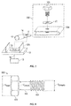
- FIG. 3 shows an example of a wire lug captivation system according to one embodiment.
- the system 300 is to be connected to include a feeder line 10 that is to be connected to a terminal block 12 of a machine via a feeder lug 14. As illustrated, electrical power is transferred between the feeder line 10 and an internal connection 16 a machine 13.
- the terminal block 12 in this embodiment includes a threaded insert 26 into which a bolt 302 is inserted.
- the bolt 302 is, in one embodiment, includes a head 400, a shank 402 and a threaded portion 404.
- the shank 402 has a diameter, d shank , that is less than the diameter, d threads , of the threads 400.
- the head 400 could be any shape and may be manipulated (e.g., turned) by any type of device).
- the head 400 could be a hex-head that that is turned by a socket wrench or it could a slot or phillips-shaped groove such that in can be rotated by a screw driver.
- the head 400 has a diameter, d head , that is greater than both d shank and d threads in one embodiment. As illustrated, the shank 402 does not include threads.
- the system 300 also includes a captivation device 304.
- the captivation device 304 is sized and arranged such that the lug 14 may be inserted into it and then the bolt 302 passed through both the captivation device 304 and the hole 15 in lug 14 and then screwed into the threads 26 in the insert 12.
- the bolt 302 may also pass through optional washer 22 before passing through the captivation device 304.
- the captivation device 304 may include an upper portion 502 and a lower portion 504.
- the upper and lower portions 502, 504 are connected by a connection portion 510.
- the connecting portion 510 is arcuate. While not illustrated it shall be understood that another connecting portion may be included on an opposing side of the upper and lower portions 502, 504 in one embodiment. Further, the particular shape of the connecting member 510 is not limited to arcuate.
- captivation device 304 may be formed by compressing a tubular section of a conductive metal (e.g., copper_ pipe.
- the upper portion 502 includes a hole 508 formed there through that includes threads 506.
- An inner diameter of the threads 506 is larger than the diameter of the shank d shank in one embodiment.
- the lower portion 504 includes a hole 511 that is concentric with hole 508 and has a diameter larger than the diameter of the threads d threads .
- lug 14 may be inserted between the upper and lower portions 502, 504. Then, the bolt 302 be threaded through the threads in the upper portion 502, and passed through the lower portion 504 (and optionally, the washer 22).
- the shank 402 may extend slightly below the lower portion 502 in one embodiment but in another it may only extent beyond a bottom edge of the threads 506 ( FIG. 5 ) of the upper portion 502.
- the assembly of the lug 14, bolt, 302 and captivation device 304 will stay together and can then be easily arranged over and screwed into the threads 26 of the terminal 12.
- such a configuration may lead to reduction is the dropping or loss of the bolt 302 as was experience in some instances as described above.
Landscapes
- Engineering & Computer Science (AREA)
- Manufacturing & Machinery (AREA)
- Connections By Means Of Piercing Elements, Nuts, Or Screws (AREA)
Applications Claiming Priority (1)
| Application Number | Priority Date | Filing Date | Title |
|---|---|---|---|
| US14/864,970 US20170093051A1 (en) | 2015-09-25 | 2015-09-25 | Wire lug captivation system and method |
Publications (2)
| Publication Number | Publication Date |
|---|---|
| EP3148004A1 true EP3148004A1 (de) | 2017-03-29 |
| EP3148004B1 EP3148004B1 (de) | 2021-03-10 |
Family
ID=57189740
Family Applications (1)
| Application Number | Title | Priority Date | Filing Date |
|---|---|---|---|
| EP16190627.6A Active EP3148004B1 (de) | 2015-09-25 | 2016-09-26 | Draht-öse-erfassungssystem und -verfahren |
Country Status (2)
| Country | Link |
|---|---|
| US (1) | US20170093051A1 (de) |
| EP (1) | EP3148004B1 (de) |
Families Citing this family (3)
| Publication number | Priority date | Publication date | Assignee | Title |
|---|---|---|---|---|
| DE102020203056A1 (de) * | 2020-03-10 | 2021-09-16 | Te Connectivity Germany Gmbh | Elektrische Schaltvorrichtung, insbesondere ein Stromschütz oder ein Relais, mit Kontaktierungselement und Befestigungselement |
| CN111376210A (zh) * | 2020-04-09 | 2020-07-07 | 峰飞国际有限公司 | 一种导电紧固机构 |
| DE102021103069A1 (de) * | 2021-02-10 | 2022-08-11 | Endress+Hauser SE+Co. KG | Erdanschlussklemme |
Citations (5)
| Publication number | Priority date | Publication date | Assignee | Title |
|---|---|---|---|---|
| DE726300C (de) * | 1939-12-24 | 1942-10-10 | Stotz Kontakt Gmbh | Nockenklemme |
| FR2333362A1 (fr) * | 1975-11-26 | 1977-06-24 | Alsthom Cgee | Borne a vis a serrage sous tete |
| DE4142034A1 (de) * | 1991-12-19 | 1993-06-24 | Bosch Gmbh Robert | Schraube |
| DE19821160C1 (de) * | 1998-05-12 | 1999-10-28 | Lemfoerder Lenksaeulen Gmbh | Befestigungssystem |
| WO2011106935A1 (en) * | 2010-03-04 | 2011-09-09 | Huawei Technologies Co., Ltd. | Screw support for securing a plurality of screws |
Family Cites Families (4)
| Publication number | Priority date | Publication date | Assignee | Title |
|---|---|---|---|---|
| US3340494A (en) * | 1965-09-13 | 1967-09-05 | Illinois Tool Works | Electrical connector device |
| GB1493220A (en) * | 1976-10-12 | 1977-11-30 | Pye Ltd | Screw or nut and a washer intended to be held captive thereon |
| US5951223A (en) * | 1998-03-23 | 1999-09-14 | San-O Industrial Corporation | Self-retaining snap-in clip |
| US9543104B2 (en) * | 2015-04-17 | 2017-01-10 | Hamilton Sundstrand Corporation | Fuse assemblies |
-
2015
- 2015-09-25 US US14/864,970 patent/US20170093051A1/en not_active Abandoned
-
2016
- 2016-09-26 EP EP16190627.6A patent/EP3148004B1/de active Active
Patent Citations (5)
| Publication number | Priority date | Publication date | Assignee | Title |
|---|---|---|---|---|
| DE726300C (de) * | 1939-12-24 | 1942-10-10 | Stotz Kontakt Gmbh | Nockenklemme |
| FR2333362A1 (fr) * | 1975-11-26 | 1977-06-24 | Alsthom Cgee | Borne a vis a serrage sous tete |
| DE4142034A1 (de) * | 1991-12-19 | 1993-06-24 | Bosch Gmbh Robert | Schraube |
| DE19821160C1 (de) * | 1998-05-12 | 1999-10-28 | Lemfoerder Lenksaeulen Gmbh | Befestigungssystem |
| WO2011106935A1 (en) * | 2010-03-04 | 2011-09-09 | Huawei Technologies Co., Ltd. | Screw support for securing a plurality of screws |
Also Published As
| Publication number | Publication date |
|---|---|
| US20170093051A1 (en) | 2017-03-30 |
| EP3148004B1 (de) | 2021-03-10 |
Similar Documents
| Publication | Publication Date | Title |
|---|---|---|
| US9385493B2 (en) | Adjustable bus bar for power distribution equipment | |
| US9318817B2 (en) | Cable connectors of an electrical module | |
| US8647159B2 (en) | Apparatus and method for effecting electrical termination with a plurality of types of termination structures | |
| US9017112B1 (en) | Electrical wire nut with detachable break-off connectors | |
| US8500475B2 (en) | Harness connector | |
| WO2017182283A1 (de) | Leistungskontakt mit auswechselbarem kontaktbereich | |
| EP3148004B1 (de) | Draht-öse-erfassungssystem und -verfahren | |
| US8672701B2 (en) | Cable connection device | |
| US9598061B2 (en) | Electrohydraulic or electromechanical motor vehicle control device | |
| US9873392B2 (en) | Terminal connection assembly for vehicle power distribution device | |
| RU162466U1 (ru) | Штепсельный узел элементов электрической цепи | |
| US9871331B2 (en) | Modular switchgear connection and method of electrically connecting a modular compartment to a switchgear assembly | |
| JP2017208303A (ja) | プラグコネクタ及び電源回路遮断装置 | |
| KR101744660B1 (ko) | 컷아우트스위치의 상하 접속부 배전선로 연결체 | |
| US20110281460A1 (en) | Twisted Quick Connector | |
| US20080166930A1 (en) | Electrical connector | |
| JP5637364B2 (ja) | ボルト締結構造 | |
| US10181710B1 (en) | Electrical connection box | |
| EP3696917A1 (de) | Elektrisches steckverbindersystem | |
| CN206712053U (zh) | 一种集成式接线端子及控制器 | |
| CN109149162A (zh) | 一种机车线缆接线装置 | |
| DE102009031224B3 (de) | Geräteschalter für elektrisch gebremste Elektrowerkzeuge | |
| EP3086352A1 (de) | Sicherungsanordnungen | |
| US20150099405A1 (en) | Mechanical Lug | |
| EP1932224B1 (de) | Verbinder |
Legal Events
| Date | Code | Title | Description |
|---|---|---|---|
| PUAI | Public reference made under article 153(3) epc to a published international application that has entered the european phase |
Free format text: ORIGINAL CODE: 0009012 |
|
| STAA | Information on the status of an ep patent application or granted ep patent |
Free format text: STATUS: THE APPLICATION HAS BEEN PUBLISHED |
|
| AK | Designated contracting states |
Kind code of ref document: A1 Designated state(s): AL AT BE BG CH CY CZ DE DK EE ES FI FR GB GR HR HU IE IS IT LI LT LU LV MC MK MT NL NO PL PT RO RS SE SI SK SM TR |
|
| AX | Request for extension of the european patent |
Extension state: BA ME |
|
| STAA | Information on the status of an ep patent application or granted ep patent |
Free format text: STATUS: REQUEST FOR EXAMINATION WAS MADE |
|
| 17P | Request for examination filed |
Effective date: 20170928 |
|
| RBV | Designated contracting states (corrected) |
Designated state(s): AL AT BE BG CH CY CZ DE DK EE ES FI FR GB GR HR HU IE IS IT LI LT LU LV MC MK MT NL NO PL PT RO RS SE SI SK SM TR |
|
| STAA | Information on the status of an ep patent application or granted ep patent |
Free format text: STATUS: EXAMINATION IS IN PROGRESS |
|
| 17Q | First examination report despatched |
Effective date: 20190329 |
|
| GRAP | Despatch of communication of intention to grant a patent |
Free format text: ORIGINAL CODE: EPIDOSNIGR1 |
|
| STAA | Information on the status of an ep patent application or granted ep patent |
Free format text: STATUS: GRANT OF PATENT IS INTENDED |
|
| INTG | Intention to grant announced |
Effective date: 20200414 |
|
| RIC1 | Information provided on ipc code assigned before grant |
Ipc: F16B 41/00 20060101ALN20200330BHEP Ipc: H01R 4/30 20060101AFI20200330BHEP |
|
| RAP1 | Party data changed (applicant data changed or rights of an application transferred) |
Owner name: HAMILTON SUNDSTRAND CORPORATION |
|
| GRAJ | Information related to disapproval of communication of intention to grant by the applicant or resumption of examination proceedings by the epo deleted |
Free format text: ORIGINAL CODE: EPIDOSDIGR1 |
|
| STAA | Information on the status of an ep patent application or granted ep patent |
Free format text: STATUS: EXAMINATION IS IN PROGRESS |
|
| INTC | Intention to grant announced (deleted) | ||
| GRAP | Despatch of communication of intention to grant a patent |
Free format text: ORIGINAL CODE: EPIDOSNIGR1 |
|
| STAA | Information on the status of an ep patent application or granted ep patent |
Free format text: STATUS: GRANT OF PATENT IS INTENDED |
|
| RIC1 | Information provided on ipc code assigned before grant |
Ipc: F16B 41/00 20060101ALN20200831BHEP Ipc: H01R 4/30 20060101AFI20200831BHEP |
|
| INTG | Intention to grant announced |
Effective date: 20200928 |
|
| GRAS | Grant fee paid |
Free format text: ORIGINAL CODE: EPIDOSNIGR3 |
|
| GRAA | (expected) grant |
Free format text: ORIGINAL CODE: 0009210 |
|
| STAA | Information on the status of an ep patent application or granted ep patent |
Free format text: STATUS: THE PATENT HAS BEEN GRANTED |
|
| AK | Designated contracting states |
Kind code of ref document: B1 Designated state(s): AL AT BE BG CH CY CZ DE DK EE ES FI FR GB GR HR HU IE IS IT LI LT LU LV MC MK MT NL NO PL PT RO RS SE SI SK SM TR |
|
| REG | Reference to a national code |
Ref country code: GB Ref legal event code: FG4D |
|
| REG | Reference to a national code |
Ref country code: AT Ref legal event code: REF Ref document number: 1370836 Country of ref document: AT Kind code of ref document: T Effective date: 20210315 Ref country code: CH Ref legal event code: EP |
|
| REG | Reference to a national code |
Ref country code: IE Ref legal event code: FG4D |
|
| REG | Reference to a national code |
Ref country code: DE Ref legal event code: R096 Ref document number: 602016053919 Country of ref document: DE |
|
| RAP4 | Party data changed (patent owner data changed or rights of a patent transferred) |
Owner name: HAMILTON SUNDSTRAND CORPORATION |
|
| REG | Reference to a national code |
Ref country code: LT Ref legal event code: MG9D |
|
| PG25 | Lapsed in a contracting state [announced via postgrant information from national office to epo] |
Ref country code: NO Free format text: LAPSE BECAUSE OF FAILURE TO SUBMIT A TRANSLATION OF THE DESCRIPTION OR TO PAY THE FEE WITHIN THE PRESCRIBED TIME-LIMIT Effective date: 20210610 Ref country code: HR Free format text: LAPSE BECAUSE OF FAILURE TO SUBMIT A TRANSLATION OF THE DESCRIPTION OR TO PAY THE FEE WITHIN THE PRESCRIBED TIME-LIMIT Effective date: 20210310 Ref country code: GR Free format text: LAPSE BECAUSE OF FAILURE TO SUBMIT A TRANSLATION OF THE DESCRIPTION OR TO PAY THE FEE WITHIN THE PRESCRIBED TIME-LIMIT Effective date: 20210611 Ref country code: FI Free format text: LAPSE BECAUSE OF FAILURE TO SUBMIT A TRANSLATION OF THE DESCRIPTION OR TO PAY THE FEE WITHIN THE PRESCRIBED TIME-LIMIT Effective date: 20210310 Ref country code: LT Free format text: LAPSE BECAUSE OF FAILURE TO SUBMIT A TRANSLATION OF THE DESCRIPTION OR TO PAY THE FEE WITHIN THE PRESCRIBED TIME-LIMIT Effective date: 20210310 Ref country code: BG Free format text: LAPSE BECAUSE OF FAILURE TO SUBMIT A TRANSLATION OF THE DESCRIPTION OR TO PAY THE FEE WITHIN THE PRESCRIBED TIME-LIMIT Effective date: 20210610 |
|
| REG | Reference to a national code |
Ref country code: AT Ref legal event code: MK05 Ref document number: 1370836 Country of ref document: AT Kind code of ref document: T Effective date: 20210310 |
|
| REG | Reference to a national code |
Ref country code: NL Ref legal event code: MP Effective date: 20210310 |
|
| PG25 | Lapsed in a contracting state [announced via postgrant information from national office to epo] |
Ref country code: SE Free format text: LAPSE BECAUSE OF FAILURE TO SUBMIT A TRANSLATION OF THE DESCRIPTION OR TO PAY THE FEE WITHIN THE PRESCRIBED TIME-LIMIT Effective date: 20210310 Ref country code: LV Free format text: LAPSE BECAUSE OF FAILURE TO SUBMIT A TRANSLATION OF THE DESCRIPTION OR TO PAY THE FEE WITHIN THE PRESCRIBED TIME-LIMIT Effective date: 20210310 Ref country code: RS Free format text: LAPSE BECAUSE OF FAILURE TO SUBMIT A TRANSLATION OF THE DESCRIPTION OR TO PAY THE FEE WITHIN THE PRESCRIBED TIME-LIMIT Effective date: 20210310 |
|
| PG25 | Lapsed in a contracting state [announced via postgrant information from national office to epo] |
Ref country code: NL Free format text: LAPSE BECAUSE OF FAILURE TO SUBMIT A TRANSLATION OF THE DESCRIPTION OR TO PAY THE FEE WITHIN THE PRESCRIBED TIME-LIMIT Effective date: 20210310 |
|
| PG25 | Lapsed in a contracting state [announced via postgrant information from national office to epo] |
Ref country code: CZ Free format text: LAPSE BECAUSE OF FAILURE TO SUBMIT A TRANSLATION OF THE DESCRIPTION OR TO PAY THE FEE WITHIN THE PRESCRIBED TIME-LIMIT Effective date: 20210310 Ref country code: EE Free format text: LAPSE BECAUSE OF FAILURE TO SUBMIT A TRANSLATION OF THE DESCRIPTION OR TO PAY THE FEE WITHIN THE PRESCRIBED TIME-LIMIT Effective date: 20210310 Ref country code: AT Free format text: LAPSE BECAUSE OF FAILURE TO SUBMIT A TRANSLATION OF THE DESCRIPTION OR TO PAY THE FEE WITHIN THE PRESCRIBED TIME-LIMIT Effective date: 20210310 Ref country code: SM Free format text: LAPSE BECAUSE OF FAILURE TO SUBMIT A TRANSLATION OF THE DESCRIPTION OR TO PAY THE FEE WITHIN THE PRESCRIBED TIME-LIMIT Effective date: 20210310 |
|
| PG25 | Lapsed in a contracting state [announced via postgrant information from national office to epo] |
Ref country code: SK Free format text: LAPSE BECAUSE OF FAILURE TO SUBMIT A TRANSLATION OF THE DESCRIPTION OR TO PAY THE FEE WITHIN THE PRESCRIBED TIME-LIMIT Effective date: 20210310 Ref country code: RO Free format text: LAPSE BECAUSE OF FAILURE TO SUBMIT A TRANSLATION OF THE DESCRIPTION OR TO PAY THE FEE WITHIN THE PRESCRIBED TIME-LIMIT Effective date: 20210310 Ref country code: ES Free format text: LAPSE BECAUSE OF FAILURE TO SUBMIT A TRANSLATION OF THE DESCRIPTION OR TO PAY THE FEE WITHIN THE PRESCRIBED TIME-LIMIT Effective date: 20210310 Ref country code: PL Free format text: LAPSE BECAUSE OF FAILURE TO SUBMIT A TRANSLATION OF THE DESCRIPTION OR TO PAY THE FEE WITHIN THE PRESCRIBED TIME-LIMIT Effective date: 20210310 Ref country code: PT Free format text: LAPSE BECAUSE OF FAILURE TO SUBMIT A TRANSLATION OF THE DESCRIPTION OR TO PAY THE FEE WITHIN THE PRESCRIBED TIME-LIMIT Effective date: 20210712 Ref country code: IS Free format text: LAPSE BECAUSE OF FAILURE TO SUBMIT A TRANSLATION OF THE DESCRIPTION OR TO PAY THE FEE WITHIN THE PRESCRIBED TIME-LIMIT Effective date: 20210710 |
|
| REG | Reference to a national code |
Ref country code: DE Ref legal event code: R097 Ref document number: 602016053919 Country of ref document: DE |
|
| PLBE | No opposition filed within time limit |
Free format text: ORIGINAL CODE: 0009261 |
|
| STAA | Information on the status of an ep patent application or granted ep patent |
Free format text: STATUS: NO OPPOSITION FILED WITHIN TIME LIMIT |
|
| PG25 | Lapsed in a contracting state [announced via postgrant information from national office to epo] |
Ref country code: AL Free format text: LAPSE BECAUSE OF FAILURE TO SUBMIT A TRANSLATION OF THE DESCRIPTION OR TO PAY THE FEE WITHIN THE PRESCRIBED TIME-LIMIT Effective date: 20210310 Ref country code: DK Free format text: LAPSE BECAUSE OF FAILURE TO SUBMIT A TRANSLATION OF THE DESCRIPTION OR TO PAY THE FEE WITHIN THE PRESCRIBED TIME-LIMIT Effective date: 20210310 |
|
| 26N | No opposition filed |
Effective date: 20211213 |
|
| PG25 | Lapsed in a contracting state [announced via postgrant information from national office to epo] |
Ref country code: SI Free format text: LAPSE BECAUSE OF FAILURE TO SUBMIT A TRANSLATION OF THE DESCRIPTION OR TO PAY THE FEE WITHIN THE PRESCRIBED TIME-LIMIT Effective date: 20210310 |
|
| REG | Reference to a national code |
Ref country code: DE Ref legal event code: R119 Ref document number: 602016053919 Country of ref document: DE |
|
| PG25 | Lapsed in a contracting state [announced via postgrant information from national office to epo] |
Ref country code: IT Free format text: LAPSE BECAUSE OF FAILURE TO SUBMIT A TRANSLATION OF THE DESCRIPTION OR TO PAY THE FEE WITHIN THE PRESCRIBED TIME-LIMIT Effective date: 20210310 |
|
| REG | Reference to a national code |
Ref country code: CH Ref legal event code: PL |
|
| REG | Reference to a national code |
Ref country code: BE Ref legal event code: MM Effective date: 20210930 |
|
| PG25 | Lapsed in a contracting state [announced via postgrant information from national office to epo] |
Ref country code: IS Free format text: LAPSE BECAUSE OF FAILURE TO SUBMIT A TRANSLATION OF THE DESCRIPTION OR TO PAY THE FEE WITHIN THE PRESCRIBED TIME-LIMIT Effective date: 20210710 Ref country code: MC Free format text: LAPSE BECAUSE OF FAILURE TO SUBMIT A TRANSLATION OF THE DESCRIPTION OR TO PAY THE FEE WITHIN THE PRESCRIBED TIME-LIMIT Effective date: 20210310 |
|
| PG25 | Lapsed in a contracting state [announced via postgrant information from national office to epo] |
Ref country code: LU Free format text: LAPSE BECAUSE OF NON-PAYMENT OF DUE FEES Effective date: 20210926 Ref country code: IE Free format text: LAPSE BECAUSE OF NON-PAYMENT OF DUE FEES Effective date: 20210926 Ref country code: DE Free format text: LAPSE BECAUSE OF NON-PAYMENT OF DUE FEES Effective date: 20220401 Ref country code: BE Free format text: LAPSE BECAUSE OF NON-PAYMENT OF DUE FEES Effective date: 20210930 |
|
| PG25 | Lapsed in a contracting state [announced via postgrant information from national office to epo] |
Ref country code: LI Free format text: LAPSE BECAUSE OF NON-PAYMENT OF DUE FEES Effective date: 20210930 Ref country code: CH Free format text: LAPSE BECAUSE OF NON-PAYMENT OF DUE FEES Effective date: 20210930 |
|
| PG25 | Lapsed in a contracting state [announced via postgrant information from national office to epo] |
Ref country code: HU Free format text: LAPSE BECAUSE OF FAILURE TO SUBMIT A TRANSLATION OF THE DESCRIPTION OR TO PAY THE FEE WITHIN THE PRESCRIBED TIME-LIMIT; INVALID AB INITIO Effective date: 20160926 |
|
| P01 | Opt-out of the competence of the unified patent court (upc) registered |
Effective date: 20230522 |
|
| PG25 | Lapsed in a contracting state [announced via postgrant information from national office to epo] |
Ref country code: CY Free format text: LAPSE BECAUSE OF FAILURE TO SUBMIT A TRANSLATION OF THE DESCRIPTION OR TO PAY THE FEE WITHIN THE PRESCRIBED TIME-LIMIT Effective date: 20210310 |
|
| PG25 | Lapsed in a contracting state [announced via postgrant information from national office to epo] |
Ref country code: MK Free format text: LAPSE BECAUSE OF FAILURE TO SUBMIT A TRANSLATION OF THE DESCRIPTION OR TO PAY THE FEE WITHIN THE PRESCRIBED TIME-LIMIT Effective date: 20210310 |
|
| PG25 | Lapsed in a contracting state [announced via postgrant information from national office to epo] |
Ref country code: TR Free format text: LAPSE BECAUSE OF FAILURE TO SUBMIT A TRANSLATION OF THE DESCRIPTION OR TO PAY THE FEE WITHIN THE PRESCRIBED TIME-LIMIT Effective date: 20210310 |
|
| PG25 | Lapsed in a contracting state [announced via postgrant information from national office to epo] |
Ref country code: MT Free format text: LAPSE BECAUSE OF FAILURE TO SUBMIT A TRANSLATION OF THE DESCRIPTION OR TO PAY THE FEE WITHIN THE PRESCRIBED TIME-LIMIT Effective date: 20210310 |
|
| PGFP | Annual fee paid to national office [announced via postgrant information from national office to epo] |
Ref country code: GB Payment date: 20250820 Year of fee payment: 10 |
|
| PGFP | Annual fee paid to national office [announced via postgrant information from national office to epo] |
Ref country code: FR Payment date: 20250820 Year of fee payment: 10 |