EP3148019A1 - Steckverbinder, gummielement und ringelement - Google Patents
Steckverbinder, gummielement und ringelement Download PDFInfo
- Publication number
- EP3148019A1 EP3148019A1 EP15796380.2A EP15796380A EP3148019A1 EP 3148019 A1 EP3148019 A1 EP 3148019A1 EP 15796380 A EP15796380 A EP 15796380A EP 3148019 A1 EP3148019 A1 EP 3148019A1
- Authority
- EP
- European Patent Office
- Prior art keywords
- rubber member
- circumferential surface
- plug
- ring member
- rubber
- Prior art date
- Legal status (The legal status is an assumption and is not a legal conclusion. Google has not performed a legal analysis and makes no representation as to the accuracy of the status listed.)
- Withdrawn
Links
Images



Classifications
-
- H—ELECTRICITY
- H01—ELECTRIC ELEMENTS
- H01T—SPARK GAPS; OVERVOLTAGE ARRESTERS USING SPARK GAPS; SPARKING PLUGS; CORONA DEVICES; GENERATING IONS TO BE INTRODUCED INTO NON-ENCLOSED GASES
- H01T13/00—Sparking plugs
- H01T13/02—Details
- H01T13/04—Means providing electrical connection to sparking plugs
-
- F—MECHANICAL ENGINEERING; LIGHTING; HEATING; WEAPONS; BLASTING
- F02—COMBUSTION ENGINES; HOT-GAS OR COMBUSTION-PRODUCT ENGINE PLANTS
- F02P—IGNITION, OTHER THAN COMPRESSION IGNITION, FOR INTERNAL-COMBUSTION ENGINES; TESTING OF IGNITION TIMING IN COMPRESSION-IGNITION ENGINES
- F02P13/00—Sparking plugs structurally combined with other parts of internal-combustion engines
-
- F—MECHANICAL ENGINEERING; LIGHTING; HEATING; WEAPONS; BLASTING
- F02—COMBUSTION ENGINES; HOT-GAS OR COMBUSTION-PRODUCT ENGINE PLANTS
- F02P—IGNITION, OTHER THAN COMPRESSION IGNITION, FOR INTERNAL-COMBUSTION ENGINES; TESTING OF IGNITION TIMING IN COMPRESSION-IGNITION ENGINES
- F02P7/00—Arrangements of distributors, circuit-makers or -breakers, e.g. of distributor and circuit-breaker combinations or pick-up devices
- F02P7/02—Arrangements of distributors, circuit-makers or -breakers, e.g. of distributor and circuit-breaker combinations or pick-up devices of distributors
-
- H—ELECTRICITY
- H01—ELECTRIC ELEMENTS
- H01R—ELECTRICALLY-CONDUCTIVE CONNECTIONS; STRUCTURAL ASSOCIATIONS OF A PLURALITY OF MUTUALLY-INSULATED ELECTRICAL CONNECTING ELEMENTS; COUPLING DEVICES; CURRENT COLLECTORS
- H01R13/00—Details of coupling devices of the kinds covered by groups H01R12/70 or H01R24/00 - H01R33/00
- H01R13/46—Bases; Cases
- H01R13/533—Bases, cases made for use in extreme conditions, e.g. high temperature, radiation, vibration, corrosive environment, pressure
-
- F—MECHANICAL ENGINEERING; LIGHTING; HEATING; WEAPONS; BLASTING
- F02—COMBUSTION ENGINES; HOT-GAS OR COMBUSTION-PRODUCT ENGINE PLANTS
- F02P—IGNITION, OTHER THAN COMPRESSION IGNITION, FOR INTERNAL-COMBUSTION ENGINES; TESTING OF IGNITION TIMING IN COMPRESSION-IGNITION ENGINES
- F02P1/00—Installations having electric ignition energy generated by magneto- or dynamo- electric generators without subsequent storage
-
- F—MECHANICAL ENGINEERING; LIGHTING; HEATING; WEAPONS; BLASTING
- F02—COMBUSTION ENGINES; HOT-GAS OR COMBUSTION-PRODUCT ENGINE PLANTS
- F02P—IGNITION, OTHER THAN COMPRESSION IGNITION, FOR INTERNAL-COMBUSTION ENGINES; TESTING OF IGNITION TIMING IN COMPRESSION-IGNITION ENGINES
- F02P3/00—Other installations
Definitions
- the present invention relates to a plug connector such as a plug cap for connection to a spark plug.
- the present invention also relates to a rubber member and a ring member of the plug connector.
- a spark plug is used in an internal combustion engine, with a plug connector such as plug cap or plug cord attached to the spark plug.
- a plug cap of the type that includes: a hollow insulating member made of a rubber material (hereinafter referred to as "rubber member") and having a front end portion engageable with a terminal electrode of a spark plug and a rear end portion engageable with a high-voltage cord for power supply to the spark plug; and a resistor disposed in a hollow portion of the rubber member (see e.g. Patent Document 1).
- This plug cap establishes a seal between the rubber member and an outer circumferential surface of an insulator of the spark plug by contact of the front end portion of the rubber member with the outer circumferential surface of the insulator of the spark plug, so as to prevent current leakage (i.e. leakage of electric current) through between an inner circumferential surface of the rubber member and the outer circumferential surface of the insulator.
- Patent Document 1 Japanese Unexamined Utility Model Application Publication No. S52-19685
- the present invention has been made to address at least part of the above problems and can be embodied as the following application examples.
- a plug connector comprising:
- the contact pressure between an inner circumferential surface of the rubber member and an outer circumferential surface of the insulator of the spark plug is increased by the ring member. It is therefore possible to increase the sealing between the rubber member and the spark plug and improve the current leakage resistance of the plug connector.
- the conductive part includes a metal connector member connectable to the terminal electrode; and wherein a rear end of the at least one ring member is located on a rear side with respect to a front end of the metal connector member.
- Vibration of the plug connector leads to the generation of a powder (e.g. metal powder) from the conductive part inside the plug connector.
- a powder e.g. metal powder
- Such a metal powder becomes a cause of current leakage.
- the rear end of the ring member which is higher in hardness than the rubber member, is located on the rear side with respect to the front end of the metal connector member so that vibration of the plug connector is suppressed. It is thus possible to increase the vibration resistance of the plug connector for further improvement in current leakage resistance.
- the plug connector according to Application Example 1 or 2 further comprising a high hardness part arranged on an outer circumference of the conductive part and having higher hardness than that of the rubber member, wherein the rubber member covers the high hardness part.
- the ring member which is higher in hardness than the rubber member, is located on the rear side with respect to the front end of the high hardness part, which is higher in hardness than the rubber member, so that the vibration resistance of the plug connector is further increased. It is thus possible to further improve the current leakage resistance of the plug connector.
- the plug connector according to any one of Application Examples 1 to 4, wherein the rubber member has at least one of a recess and a protrusion formed on an outer circumferential surface thereof according to the shape of an inner circumferential surface portion including at least a part of an inner circumferential surface of the at least one ring member.
- the plug connector according to Application Example 1 further comprising at least one of a metal connector member and a high hardness part, the metal connector member being connectable to the terminal electrode and covered by the rubber member, the high hardness part being arranged on an outer circumference of the conductive part and having higher hardness than that of the rubber member, wherein the at least one ring member includes a contact portion located at a position overlapping the at least one of the metal connector member and the high hardness part in an axis direction of the plug connector and brought into contact with an outer circumferential surface of the rubber member.
- the ring member is brought into contact with the rubber member at the location where the relatively hard ring member and the relatively hard metal connector member or high hardness part overlap in position in the axis direction. It is thus possible to further improve the vibration resistance of the plug connector.
- the contact portion of the ring member is brought into contact with the rubber member at adequate pressure. It is thus possible to further improve the vibration resistance of the plug connector.
- the first protrusion of the contact portion of the ring member is brought into contact with the outer circumferential surface of the rubber member so that the contact pressure between the contact portion and the rubber member is stabilized. It is thus possible to further improve the vibration resistance of the plug connector.
- the second protrusion of the rubber member is brought into contact with the inner circumferential surface of the contact portion of the ring member so that the contact pressure between the contact portion and the rubber member is stabilized. It is thus possible to further improve the vibration resistance of the plug connector.
- the contact portion of the ring member is brought into contact with the rubber member at more adequate pressure. It is thus possible to further improve the vibration resistance of the plug connector.
- the ring member is arranged on the outer circumference of the rubber member to enhance the press contact between the insulator of the spark plug and the rubber member. Further, displacement of the ring member relative to the rubber member is suppressed by the recess or protrusion. It is therefore possible to increase the sealing between the rubber member and the spark plug for improvement in current leakage resistance.
- a ring member for use with a rubber member the rubber member covering a conductive part that provides electrical connection between a spark plug and a power supply member for power supply to the spark plug, the spark plug comprising an insulator and a terminal electrode protruding toward the rear from a rear end of the insulator, wherein the ring member is arranged on an outer circumference of the rubber member so as to, when the spark plug is inserted in one end portion of the rubber member, increase a contact pressure between the insulator and the rubber member.
- the ring member is arranged to enhance the press contact between the insulator of the spark plug and the rubber member. It is therefore possible to increase the sealing between the rubber member and the spark plug for improvement in current leakage resistance.
- the ring member according to Application Example 12 wherein the ring member has at least one of a recess and a protrusion formed on an inner circumferential surface thereof.
- the present invention can be embodied in various forms such as not only a plug cap for a spark plug but also a plug cord for a spark plug, an ignition coil unit for a spark plug and the like.
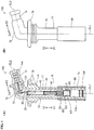
- FIG. 1 shows a plug cap 100 according to the first embodiment of the present invention, where FIG. 1(A) is a cross-sectional view of the plug cap 100; and FIG. 1(B) is an external view of the plug cap 100.
- the plug cap 100 includes a resin part 10, a cord fixing screw 20, a metal plate 40, a connection spring 40, a resistor 50, a metal connector member 60, a rubber member 70 and a ring member 80 in the first embodiment.
- the resin part 10 is made of a high heat-resistant thermosetting resin such as unsaturated polyester resin or phenol resin. Namely, the resin part 10 is made of a resin material having higher hardness than that of the rubber member 70. The resin part 10 is accordingly also called "high hardness part”.
- the expression "hardness” used herein refers to a hardness value as measured according to the method defined by JIS K 6253:2012 (i.e. durometer type spring method).
- the resin part 10 includes a first structure portion 11 formed in a cylindrical shape along a first axis CL1 and a second structure portion 12 formed in a cylindrical shape along a second axis CL2.
- the cylindrical shape is not necessarily perfect circular cylindrical and may be substantially cylindrical.
- the outer or inner diameter of the cylindrical shape may vary depending on the position in the axis direction
- first direction D1 the direction toward the lower side of FIG. 1 in parallel to the first axis CL1
- second direction D2 the direction toward the upper side of FIG. 1 in parallel to the first axis CL1
- third direction D3 the direction from the lower left side to the upper right side of FIG. 1 in parallel to the second axis CL2
- fourth direction D4 the direction from the upper right side to the lower left side of FIG. 1 in parallel to the second axis CL2
- the angle formed between the first axis CL1 and the second axis CL2, i.e., the angle (minor angle) formed between the first structure portion 11 and the second structure portion 12 is set to about 100 degrees.
- the angle between the first and second structure portions 11 and 12 is not however limited to this value and may be set to any other value e.g. 60 degrees, 90 degrees or 120 degrees.
- the first structure portion 11 has a first hole 11A formed therein with a first direction D1 end thereof open and a second direction D2 end thereof closed.
- the first hole 11A is circular cylindrical in shape along the first axis CL1.
- the second structure portion 12 has a second hole 12A formed therein with a third direction D1 end thereof open and a fourth direction D4 end thereof closed.
- the second hole 12A is circular cylindrical in shape along the second axis CL2.
- the cord fixing screw 20 is made of a conductive metal material (such as brass).
- the cord fixing screw 20 includes a head portion oriented in the fourth direction D4 and a male thread portion oriented in the third direction D3.
- the head portion of the cord fixing screw 20 is embedded in a region of the resin part 10 between the first hole 11A and the second hole 12A.
- the male thread portion of the cord fixing screw 20 is arranged inside the second hole 12A.
- the cord fixing screw 20 is used to connect a plug cord (not shown) to the plug cap 100.
- the plug cord serves as a power supply member for power supply to a spark plug.
- an end portion of the plug cord is inserted in the second hole 12A and screwed onto the cord fixing screw 20.
- a lead wire inside the plug cord is electrically connected to the cord fixing screw 20.
- the spring 40 is made of a conductive metal member (such as stainless steel) and is arranged inside the first hole 11A in a state of being compressed in the direction of the first axis CL1.
- the metal plate 30 is made of a conductive metal material (such as brass) and is embedded in a region of the resin part 10 between the bottom of the first hole 11A and the bottom of the second hole 12A. A second direction D2 end of the metal plate 30 is brought into contact with the head portion of the cord fixing screw 20. A first direction D1 end of the metal plate 30 is exposed inside the first hole 11A and brought into contact with a spring bearing 31.
- the spring bearing 31 is provided with a recess such that the connection spring 40 is fixed in the spring bearing 31 by placing a second direction D2 end of the connection spring 40 in the recess and crimping the spring bearing 31 from the radially outer circumferential side.
- the resistor 50 is cylindrical-shaped and arranged inside the first hole 11A at a location on the first direction D1 side with respect to the connection spring 40. A second direction D2 end of the resistor 50 is brought into contact with a first direction D1 end of the connection spring 40.
- the resistor 50 is made of a conductive ceramic material with a predetermined resistance (e.g. 5 k ⁇ ) and is used for suppression of electrical noise.
- the metal connector member 60 is made of a conductive metal material (such as brass) in a cylindrical shape.
- the metal connector member 60 includes a head portion 61 and an exposure portion 63 arranged on the first direction D1 side of the head portion 61.
- the head portion 61 is fixed by screwing in the first hole 11A of the first structure portion 11.
- a second direction D2 end of the head portion 61 is brought into contact with a first direction D1 end of the resistor 50.
- the exposure portion 63 is exposed from the open end of the first hole 11A of the first structure portion 11, that is, protrudes in the first direction D1 from a first direction D1 end of the first structure portion 11.
- a plug insertion hole 65 is formed in the exposure portion 63 such that, at the time of use of the plug cap 100, a terminal electrode on the rear end of the spark plug (not shown) is inserted in the plug insertion hole 65 from the first direction D1 side toward the second direction D2 side.
- a groove 631 is formed in an outer circumference of the exposure portion 63 such that an annular connector spring 3 is engaged in the groove 631.
- a cut is formed in the groove 631 in communication with the plug insertion hole 65.
- a part of the connector spring 3, when engaged in the groove 631, is exposed to the plug insertion hole 65 through the cut.
- the terminal electrode of the spark plug inserted in the plug insertion hole 65 is fixed in the plug insertion hole 65 by the part of the connector spring 3 exposed to the plug insertion hole 65.
- the cord fixing screw 20, the metal plate 30, the spring bearing 31, the connection spring 40, the resistor 50 and the metal connector member 60 are electrically conductive and electrically connected to one another.
- These conductive components 20 to 60 function together as a conductive part to provide electrical connection between the plug cord and the spark plug upon connection of the plug cord to the cord fixing screw 20 and connection of the spark plug to the metal connector member 60.
- the resin part 10 functions as a resin insulator arranged around the conductive components 20 to 60.
- the rubber member 70 is made of a rubber material such as silicone rubber. In the first embodiment, the rubber member 70 is arranged to cover not only the resin part 10 but also the whole of the conductive components 20 to 60.
- the rubber member 70 includes a first body portion 71 arranged on an outer circumference of the first structure portion 11 of the resin part 10 and a second body portion 72 arranged on an outer circumference of the second structure portion 12 of the resin part 10.
- the rubber member 70 also includes a plug cover portion 73 arranged on the first direction D1 side of the first body portion 71 and a cord cover portion 74 arranged on the third direction D3 side of the second body portion 72.
- the plug cover portion 73 has a cylindrical shape with a hole 73A defined by an inner circumferential surface 73F thereof.
- the inner circumferential surface 73F of the plug cover portion 73 is brought into intimate contact with an outer circumferential surface of the spark plug so as to prevent the occurrence of current leakage through between the inner circumferential surface 73F and an outer circumferential surface of an insulator (insulating part) IN of the spark plug SP and to avoid the entry of water from the outside into the plug cap 100 and thereby reduce the possibility of current leakage caused by such water entry.
- the outer diameter of the first body portion 71 is set equal to the outer diameter of the plug cover portion 73.
- the cord cover portion 74 has a cylindrical shape with a hole 74A defined by an inner circumferential surface thereof. In a state where the plug cord (not shown) is connected to the cord fixing screw 20 of the plug cap 100, the inner circumferential surface of the cord cover portion 74 is brought into intimate contact with an outer circumferential surface of the plug cord so as to prevent the occurrence of current leakage and to avoid the entry of water from the outside into the plug cap 100.
- the rubber member 70 is brought at one end portion (third direction D3 side portion) thereof into contact with the outer circumferential surface of the plug cord and at the other end portion (first direction D1 end portion) thereof into contact with the outer circumferential surface of the spark plug during use of the plug cap 100.
- a fixing portion 75 is formed on an outer circumference of the first body portion 71 such that the plug cap 100 is fixed in a plug hole of an internal combustion engine (not shown) by means of the fixing portion 75.
- the ring member 80 is made of a material having higher hardness than that of the rubber member 70.
- the ring member 80 can be made of a thermosetting resin such as unsaturated polyester resin or phenol resin as in the case of the resin part 10.
- FIG. 2 is a cross-sectional view of the vicinity of the ring member 80 of the plug cap 100 in a state where the spark plug SP is connected to the plug cap 100 by insertion in one end portion (plug cover 73 side end portion) of the rubber member 70.
- the spark plug SP has the insulator IN and the terminal electrode TE protruding toward the rear (second direction D2 side) from a rear end (second direction D2 end) of the insulator IN.
- the terminal electrode TE is inserted in the plug insertion hole 65 of the metal connector member 60.
- the insulator IN is arranged in the hole 73A of the plug cover portion 73. In this state, the outer circumferential surface of the insulator IN of the spark plug SP is brought into contact with the inner circumferential surface of the plug cover portion 73.
- the ring member 80 is arranged on an outer circumference of the rubber member 70 (more specifically, on outer circumferences of the first body portion 71 and the plug cover portion 73).
- the ring member 80 has a first direction D1 end 81 located at the same position in the axis direction (i.e. the direction of the axis CL1) as a first direction D1 end of the plug cover portion 73.
- the first direction D1 end 81 of the ring member 80 is located on the front side (first direction D1 side) with respect to the rear end (second direction D2 end) of the insulator IN of the spark plug SP in the axis direction during use of the plug cap.
- the ring member 80 has a second direction D2 end 82 located on the second direction D2 side with respect to the position P1 of a first direction D1 end of the metal connector member 60 in the axis direction and, at the same time, on the second direction D2 side with respect to the position P2 of the first direction D1 end of the first structure portion 11 of the resin part 10 in the axis direction. Further, the second direction D2 end 82 of the ring member 80 is located on the first direction D1 side with respect to the second direction D2 end of the rubber member 70 in the axis direction.
- the outer circumferential surface of the insulator IN of the spark plug SP is brought into contact with the inner circumferential surface of the plug cover portion 73 such that pressure is applied from the outer circumferential surface of the insulator IN to the inner circumferential surface of the plug cover portion 73.
- the inner diameter of the ring member 80 is set smaller than the outer diameter of the plug cover portion 73 of the rubber member 70 such that pressure is applied from the inner circumferential surface of the ring member 80 to the outer circumferential surface of the plug cover portion 73.
- the front end (first direction D1 end 81) of the ring member 80 is located on the front side (first direction D1 side) with respect to the rear end (second direction D2 end) of the insulator IN of the spark plug SP. That is, the insulator IN of the spark plug SP is arranged radially inside the inner circumferential surface of the ring member 80 with the rubber member disposed therebetween.
- the pressure of contact (contact pressure) between the inner circumferential surface of the plug cover portion 73 of the rubber member 70 and the outer circumferential surface of the insulator IN of the spark plug SP is increased to increase the sealing between the rubber member and the spark plug and improve the current leakage resistance of the plug cap 100.
- the ring member 80 prevents the plug cover portion 73 from expanding radially outwardly and thereby increases the contact pressure between the inner circumferential surface of the plug cover portion 73 and the outer circumferential surface of the insulator IN of the spark plug SP. It is therefore possible to increase the sealing between the rubber member and the spark plug and improve the current leakage resistance of the plug cap so that, for example, the entry of water into the plug cap 100 is avoided to suppress a flow of leak current.
- the rear end (second direction D2 end 82) of the ring member 80 is located on the rear side (second direction D2 side) with respect to the front end (first direction D1 end) of the metal connector member 60 (see FIG. 2 ). It is thus possible to further improve the current leakage resistance of the plug cap.
- the rear end of the ring member 80 which is higher in hardness than the rubber member 70, is located on the rear side with respect to the front end of the metal connector member 60 so that vibration of the plug cap 100 is suppressed. It is thus possible to increase the vibration resistance of the plug cap 100, prevent the generation of a metal powder and thereby further improve the current leakage resistance of the plug cap 100.
- the resin part 10 (high hardness part), which is higher in hardness than the rubber member 70, is provided in the plug cap 100. It is thus possible to increase the strength of the plug cap 100 so that, for example, the vibration resistance of the plug cap 100 is further increased to suppress the generation of a metal powder and improve the current leakage resistance.
- the rear end (second direction D2 end 82) of the ring member 80 is located on the rear side with respect to the front end (first direction D1 end) of the resin part 10. That is, the rear end of the ring member 80, which is higher in hardness than the rubber member 70, is located on the rear side with respect to the front end of the resin part 10, which is higher in hardness than the rubber member 70.
- the ring member 80 and the resin part 10, both of which are relatively high in hardness, are arranged to overlap each other when viewed in the radial direction. In this arrangement, the entire outer circumference of the metal connector member 60 is covered by at least either the relatively hard ring member 80 or resin part 10 so that the vibration resistance of the plug cap 100 is further increased. It is thus possible to further improve the current leakage resistance of the plug cap 100.
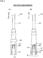
- FIG. 3 shows a plug cord 200 according to a second embodiment of the present invention, where FIG. 3(A) is a schematic view of the plug cord 200 in a state where a spark plug SP is not connected to the plug cord; and FIG. 3(B) is a schematic view of the plug cord 200 in a state where the spark plug SP is connected to the plug cord.
- the plug cord 200 includes a cord body CD, a rubber member 270 arranged on the front side (first direction D1 side) of the cord body CD, a metal connector member 260 arranged inside the rubber member 270 and a ring member 280.
- the rubber member 270 is made of a material similar to the material of the rubber member 70 of the first embodiment.
- the rubber member 270 has a cylindrical shape with its diameter gradually increasing from a second direction D2 end thereof toward the first direction D1.
- a hole 270A is formed in the rubber member 270 so as to be open in the front direction D1.
- the metal connector member 260 is used for connection of a terminal electrode TE of the spark plug SP as in the case of the metal connector member 60 of the first embodiment.
- the cord body CD is electrically connected to a second direction D2 end of the metal connector member 260.
- the metal connector member 260 functions as a conductive part to provide electrical connection between the plug cord and the spark plug in the second embodiment. It can be said that the metal connector member 260 and the rubber member 270 are configured as a simple plug cap without the resistor 50 and the connection spring 40 according to a modification of the first embodiment.
- a recess 278 is formed in a region of the outer circumferential surface of the rubber member 270 close to a first direction D1 end of the rubber member 270 over the entire circumference of the rubber member 270. As shown in FIG. 3(B) , the position of the recess 278 in the axis direction corresponds to the position of an insulator IN of the spark plug SP in the state where the spark plug SP is connected to the plug cord 200.
- the ring member 280 is made of a material similar to the material of the ring member 80 of the first embodiment, i.e., made of a material having higher hardness than that of the rubber member 270.
- the length of the ring member 280 in the axis direction is set substantially equal to the length of the recess 278 in the axis direction; and the inner diameter of the ring member 280 is set slightly smaller than the outer diameter of the recess 278.
- the recess 278 is shaped according to the shape of a portion including an inner circumferential surface of the ring member 280.
- the ring member 280 is hence shifted in the first direction D1 relative to the position of FIG. 2(A) and engaged in the recess 278.
- the terminal electrode TE of the spark plug SP is connected to the metal connector member 260 during use of the plug cord 200.
- the ring member 280 is engaged in the recess 278 of the rubber member 270 during use.
- the inner circumferential surface of the ring member 280 is consequently brought into contact with the outer circumferential surface of the recess 278 of the rubber member 270 during use of the plug cord 200 such that pressure is applied from the inner circumferential surface of the ring member 280 to the outer circumferential surface of the recess 278.
- the plug cord 200 of the second embodiment is characterized in that the front end (first direction D1 end) of the ring member 280 is located on the front side (first direction D1 side) with respect to the rear end (second direction D2 end) of the insulator IN of the spark plug SP.
- the contact pressure between the inner circumferential surface of the rubber member 270 and the outer circumferential surface of the insulator IN of the spark plug SP is increased. It is therefore possible to increase the sealing between the rubber member 270 and the spark plug SP and improve the current leakage resistance.
- the recess 278 is formed in the outer circumference of the rubber member 270 in accordance with the shape of a portion including an inner circumferential surface of the ring member 280. In this configuration, it is possible to suppress displacement of the ring member 280 relative to the rubber member 270 and avoid deterioration in the current leakage resistance of the plug cord 200 caused by displacement of the ring member 280 during use of the plug cord.
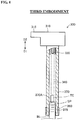
- FIG. 4 is a schematic view of an ignition coil-integrated plug cap 300 according to a third embodiment of the present invention.
- the ignition coil-integrated plug cap 300 is used by insertion into a plug hole of an internal combustion engine (not shown).
- the ignition coil-integrated plug cap 300 includes a coil unit 310, a connection spring 340, a rubber member 370 and a ring member 380.
- the coil unit 310 has an ignition coil (not shown) installed therein, a connector 315 for connection of the ignition coil to a power source (e.g. battery) and an output terminal 320 for output of power supply from the ignition coil to a spark plug SP.
- the output terminal 320 thus functions as a power supply member for power supply to the spark plug SP in the third embodiment.
- the rubber member 370 is made of a material similar to the material of the rubber member 70 of the first embodiment.
- the rubber member 370 has a cylindrical shape with a through hole 370A formed therein.
- the spark plug SP is inserted in the through hole 370A from a first direction D1 end of the rubber member 370.
- the output terminal 320 of the coil unit 310 is inserted in the through hole 370A from a second direction D2 end of the rubber member 370.
- a recess 378 is formed in a region of the outer circumferential surface of the rubber member 370 close to the first direction D1 end of the rubber member 370 over the entire circumference of the rubber member 370. As shown in FIG. 4 , the position of the recess 378 in the axis direction corresponds to the position of an insulator IN of the spark plug SP in a state where the spark plug SP is connected to the ignition coil-integrated plug cap 300.
- connection spring 340 is arranged inside the through hole 370A of the rubber member 370, in a state of being compressed in the axis direction (first direction D1 and second direction D2), at a position between the output terminal 320 of the coil unit 310 and a terminal electrode TE of the spark plug SP.
- a second direction D2 end of the connection spring 340 is brought into press contact with the output terminal 320.
- a first direction D1 end of the connection spring 340 is brought into press contact with the terminal electrode TE of the spark plug SP.
- the connection spring 340 functions as a conductive part to provide electrical connection between the output terminal 320 and the spark plug SP.
- the ring member 380 is made of a material similar to the material of the ring member 80 of the first embodiment.
- the length of the ring member 380 in the axis direction is set substantially equal to the length of the recess 378 in the axis direction; and the inner diameter of the ring member 380 is set slightly smaller than the outer diameter of the recess 378.
- the recess 378 is shaped according to the shape of a portion including an inner circumferential surface of the ring member 380. The ring member 380 is hence engaged in the recess 378.
- the terminal electrode TE of the spark plug SP is connected to the metal connector member 360 during use of the ignition coil-integrated plug cap 300.
- the inner circumferential surface of the ring member 380 is consequently brought into contact with the outer circumferential surface of the recess 378 of the rubber member 370 during use of the ignition coil-integrated plug cap 300 such that pressure is applied to the outer circumferential surface of the recess 378 as in the case of the second embodiment.
- the ignition coil-integrated plug cap 300 of the third embodiment attains the same effects as the plug cord 200 of the second embodiment. More specifically, the ignition coil-integrated plug cap 300 of the third embodiment is also characterized in that the front end (first direction D1 end) of the ring member 380 is located on the front side (first direction D1 side) with respect to the rear end (second direction D2 end) of the insulator IN of the spark plug SP. As a result, the contact pressure between the inner circumferential surface of the rubber member 370 and the outer circumferential surface of the insulator IN of the spark plug SP is increased. It is therefore possible to increase the sealing between the rubber member 370 and the spark plug SP and improve the current leakage resistance.
- the recess 378 is formed in the outer circumference of the rubber member 370, it is possible to avoid deterioration in the current leakage resistance of the ignition coil-integrated plug cap 300 caused by displacement of the ring member 380 during use of the ignition coil-integrated plug cap 300.
- FIG. 5 is a cross-sectional view of the vicinity of a ring member 80 of a plug cap according to a fourth embodiment of the present invention.
- the fourth embodiment shown in FIG. 5 is different from the first embodiment shown in FIG. 2 in that a region 73G of the inner circumferential surface of the rubber member 70 is not brought into the metal connector member 60.
- the other configurations of the plug cap of the fourth embodiment are the same as those of the first embodiment.
- the inner diameter of the rubber member 70 before attachment to the resin part 10 is set smaller than the outer diameter of the resin part 10 (first structure portion 11) and greater than the outer diameter of the exposure portion 63 of the metal connector member 60.
- the inner circumferential surface of the rubber member 70 is consequently brought into contact with the outer circumferential surface of the resin part 10 (first structure portion 11) at a certain degree of pressure. It is thus unlikely that the rubber member 70 will be circumferentially inwardly deformed.
- the inner diameter of the ring member 80 is set smaller than or equal to the outer diameter of the rubber member 70 after attachment to the resin part 10 (first structure portion 11), i.e., the outer diameter of a region of the rubber member 70 from the axial position P2 to the axial position P3 in FIG. 5 .
- the inner circumferential surface of a region of the ring member 80 from the axial position P2 to the axial position P3 in FIG. 5 is hence securely brought into contact with the outer circumferential surface of the rubber member 70 at a certain degree of pressure.
- the axial position P2 corresponds to the position of the front end of the resin part 10 (first structure portion 11); and the axial position P3 corresponds to the position of the rear end of the ring member 80.
- the portion of the ring member 80 extending from the axial position P2 to the axial position P3 for secure contact with the outer circumferential surface of the rubber member 70 is herein called "contact portion 85".
- the resin part 10 (first structure portion 11) is one example of high hardness part that is arranged around the outer circumference of the conductive part (such as resistor 50) and covered by the rubber member 70 and has higher hardness than that of the rubber member 70.
- the contact portion 85 is located at a position axially overlapping the resin part 10, as the high hardness part, and brought into contact with the outer circumferential surface of the rubber member 70.
- the length of the contact portion 85 in the axis direction is defined as "contact length L1".
- the contact portion 85 is provided in the plug cap so that the ring member 80 is brought into contact with the rubber member 70 at the location where two component parts of relatively high hardness (that is, the resin part 10 and the ring member 80) axially overlap in position as explained above. It is therefore possible to enhance the mating between the resin part 10 and the ring member 80 and further improve the vibration resistance of the plug cap.
- evaluation samples Twelve kinds of samples of the plug cap according to the fourth embodiment (referred to as “evaluation samples”) and one kind of comparative plug cap sample (referred to as “comparative sample”) were prepared and evaluated by vibration test.
- comparative sample twelve kinds of samples of the plug cap according to the fourth embodiment
- comparative plug cap sample one kind of comparative plug cap sample
- the dimensions of the ring member 80 were varied among the twelve kinds of evaluation samples.
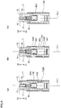
- FIG. 6 shows a cross section of the plug cap as taken along line A-A of FIG. 5 .
- FIG. 6(a) is a cross-sectional view of the plug cap as taken along line A-A of FIG. 5 , i.e., as taken though the contact portion 85 in the direction perpendicular to the axis direction.
- the metal connector member 60 is omitted from FIG. 6(a) and (b).
- FIG. 6(b) is a cross-sectional view of the plug cap as taken along line A-A of FIG. 5 in a state where the ring member 80 is not yet arranged. As shown in FIG.
- each of the outer circumferential surface of the resin part 10 (first structure portion 11), the outer circumferential surface of the rubber member 70 and the inner circumferential surface of the contact portion 85 of the ring member 80 is circular in cross section. It is now assumed that: R1 is the outer diameter of the resin part 10 (first structure portion 11) as shown in FIG. 6(a) and (b) ; R2 is the inner diameter of the ring member 80 (contact portion 85) as shown in FIG. 6(a) ; and R3 is the outer diameter of the rubber member 70 in an uncompressed state as shown in FIG. 6(b) .
- the uncompressed state herein refers to a state where the ring member 80 is not arranged on the outer circumference of the rubber member 70, that is, the rubber member 70 is not compressed radially inwardly by the inner circumferential surface of the ring member 80.
- S1 is the area occupied by the rubber member 70, i.e., the area inside a circle representing the inner circumferential surface of the contact portion 85 and outside a circle representing the outer circumferential surface of the resin part 10 in the cross section of FIG. 6(A)
- S2 is the area occupied by the rubber member 70, i.e., the area of the rubber member 70 in the uncompressed state in the cross section of FIG. 6(B) .
- the inner diameter R2 of the ring member 80 was smaller than the outer diameter R3 of the rubber member 70 in the uncompressed state (R3 ⁇ R2) so that the rubber member 70 was compressed radially inwardly by the inner circumferential surface of the ring member 80.
- Each of the four sample groups of different ratio values (S1/S2) was provided with three kinds of samples.
- the contact length L1 shown in FIG. 5 was set to different values of 5 mm, 10 mm and 15 mm.
- the evaluation samples with a ratio value (S1/S2) of 0.96 or smaller were not provided because the inner diameter R2 of the ring member 80 was too small relative to the outer diameter R3 of the rubber member 70 so that it was impossible to arrange the ring member 80 around the rubber member 70.
- the configurations of the comparative sample were the same as those of the evaluation samples except that the ring member 80 was not arranged.
- the vibration test was performed on each of the evaluation samples and the comparative sample by mounting a front end portion of a spark plug SP to a vibration test machine, with the sample attached to the spark plug SP, and then, vibrating the spark plug SP in a direction perpendicular to the axis direction.
- the spark plug SP was subjected to log sweep vibration with an acceleration of 30 G.
- the log sweep vibration was herein applied by 20 hours of repeated vibration cycles, in each of which frequency was increased from 50 Hz to 500 Hz at a logarithmic sweep rate and then decreased from 500 Hz to 50 Hz at a logarithmic sweep rate. One cycle was conducted over 6 minutes.
- the plug cap sample was detached from the spark plug SP and visually tested for the amount of a metal powder adhered to the inside of the rubber member 70.
- the metal powder was generated by shaving of the metal connector member 60 due to friction between a terminal electrode TE of the spark plug SP and the metal connector member 60. Since the metal powder becomes a cause of current leakage, it can be said that the less the amount of the metal powder generated by the vibration, the higher the vibration resistance of the sample.
- the amount of the metal powder found in the evaluation sample was evaluated with reference to the amount of the metal powder found in the comparative example.
- the evaluation grade of the comparative sample was set as "D".
- the evaluation grade of the evaluation sample was set as "A” in the case where there was found almost no metal powder.
- the evaluation grade of the evaluation sample was set as "B” in the case where the metal powder was found in a slight amount but would not be a cause of current leakage.
- the evaluation grade of the evaluation sample was set as "C” in the case where the metal powder was found in a certain amount such that the possibility of current leakage could not be denied.
- TABLE 1 shows the evaluation test results. All of the evaluation samples had an evaluation grade of "C” or higher. There was no evaluation sample with an evaluation grade of "D”. It has been apparent from these results that it is possible to improve the vibration resistance of the plug cap by the arrangement of the ring member 80.
- the three evaluation samples in which the ratio (S1/S2) was 1 had an evaluation grade of "C” irrespective of the contact length L1.
- the nine evaluation samples in which the ratio (S1/S2) was 0.99 or smaller had an evaluation grade of "B” or higher.
- the plug cap of the fourth embodiment it has been shown by the evaluation test results that it is preferable for the plug cap of the fourth embodiment to satisfy the condition of 0.97 ⁇ (S1/S2) ⁇ 0.99.
- the contact portion 85 of the ring member 80 is brought into contact with the rubber member 70 at adequate pressure. It is thus possible to further improve the vibration resistance of the plug cap.
- the contact length L1 is smaller than or equal to 10 mm.
- the ring member 80 is brought into contact with the rubber member 70 at adequate pressure without causing excessive mating force between the resin part 10 and the ring member 80. It is thus possible to further improve the vibration resistance of the plug cap.
- the present invention is suitably applicable to a plug connector such as plug cap and to a rubber member and a ring member of the plug connector.
Landscapes
- Engineering & Computer Science (AREA)
- Chemical & Material Sciences (AREA)
- Combustion & Propulsion (AREA)
- Mechanical Engineering (AREA)
- General Engineering & Computer Science (AREA)
- Ignition Installations For Internal Combustion Engines (AREA)
- Spark Plugs (AREA)
Applications Claiming Priority (2)
| Application Number | Priority Date | Filing Date | Title |
|---|---|---|---|
| JP2014103862 | 2014-05-19 | ||
| PCT/JP2015/063835 WO2015178278A1 (ja) | 2014-05-19 | 2015-05-13 | プラグ接続具、ゴム部材、および、リング部材 |
Publications (2)
| Publication Number | Publication Date |
|---|---|
| EP3148019A1 true EP3148019A1 (de) | 2017-03-29 |
| EP3148019A4 EP3148019A4 (de) | 2018-01-24 |
Family
ID=54553951
Family Applications (1)
| Application Number | Title | Priority Date | Filing Date |
|---|---|---|---|
| EP15796380.2A Withdrawn EP3148019A4 (de) | 2014-05-19 | 2015-05-13 | Steckverbinder, gummielement und ringelement |
Country Status (5)
| Country | Link |
|---|---|
| US (1) | US10079475B2 (de) |
| EP (1) | EP3148019A4 (de) |
| JP (1) | JP6067871B2 (de) |
| CA (1) | CA2945273C (de) |
| WO (1) | WO2015178278A1 (de) |
Families Citing this family (2)
| Publication number | Priority date | Publication date | Assignee | Title |
|---|---|---|---|---|
| JP4320870B2 (ja) * | 1999-10-18 | 2009-08-26 | 住友化学株式会社 | (+)−トランス第一菊酸の製造方法 |
| DE102018108292B4 (de) * | 2017-11-17 | 2023-05-11 | Borgwarner Ludwigsburg Gmbh | Verbindungsstecker zum Anschließen einer Zündspule an eine Zündkerze sowie Schutzrohr für einen Verbindungsstecker |
Family Cites Families (22)
| Publication number | Priority date | Publication date | Assignee | Title |
|---|---|---|---|---|
| US2730562A (en) * | 1951-01-11 | 1956-01-10 | Nat Products Corp | Waterproof spark plug shield |
| US3219864A (en) | 1962-09-13 | 1965-11-23 | Harvey G Allman | Spark plug connection |
| FR2312126A1 (fr) * | 1975-05-21 | 1976-12-17 | Mayer Ferdy | Dispositif antiparasites pour moteur a explosions |
| JPS5219685U (de) | 1975-07-30 | 1977-02-12 | ||
| SE436671B (sv) | 1983-08-05 | 1985-01-14 | Saab Scania Ab | Anslutningsdon vid tendsystem till en forbrenningsmotors tendstift |
| DE3600511A1 (de) * | 1985-05-31 | 1986-12-04 | Robert Bosch Gmbh, 7000 Stuttgart | Zuendkerze fuer brennkraftmaschinen |
| DE3701396A1 (de) | 1987-01-20 | 1988-07-28 | Bremicker Auto Elektrik | Zuendkerzenentstoerstecker |
| FR2643194B1 (fr) * | 1989-02-14 | 1993-12-17 | Musorb Application Ferrites | Dispositif de connexion electrique d'un cable, notamment d'allumage, sur un plot |
| US5145433A (en) * | 1989-07-14 | 1992-09-08 | Yazaki Corporation | High tension cable device and process of producing the same |
| JP2695738B2 (ja) * | 1992-07-17 | 1998-01-14 | 川崎重工業株式会社 | 点火プラグキャップ |
| US5297971A (en) * | 1992-07-17 | 1994-03-29 | Kawasaki Jukogyo Kabushiki Kaisha | Spark plug cap |
| DE4342899C1 (de) * | 1993-12-16 | 1995-06-08 | Bosch Gmbh Robert | Stecker, insbesondere für Zünd- oder Glühkerzen |
| US5716223A (en) * | 1996-02-29 | 1998-02-10 | General Motors Corporation | Spark plug boot insulator |
| US5813872A (en) * | 1996-03-06 | 1998-09-29 | Cooper Technologies Company | Automotive spark plug cover |
| JP3327151B2 (ja) | 1996-12-25 | 2002-09-24 | 住友電装株式会社 | 高圧電線の端末部カバー構造 |
| JP2001085139A (ja) * | 1999-09-16 | 2001-03-30 | Mitsubishi Electric Corp | 内燃機関用点火装置の高圧接続部構造 |
| JP4431266B2 (ja) * | 2000-11-13 | 2010-03-10 | 日本特殊陶業株式会社 | 圧力センサ内蔵型スパークプラグユニット |
| JP4793857B2 (ja) * | 2005-12-27 | 2011-10-12 | 本田技研工業株式会社 | 自動二輪車のプラグキャップ取付構造体 |
| US8198791B2 (en) * | 2008-04-02 | 2012-06-12 | Ngk Spark Plug Co., Ltd. | Spark plug, and method for manufacturing the same |
| CN103227420A (zh) * | 2009-01-23 | 2013-07-31 | 日本特殊陶业株式会社 | 内燃机用火花塞 |
| JP5185990B2 (ja) * | 2009-12-21 | 2013-04-17 | 日本特殊陶業株式会社 | スパークプラグ及びその製造方法 |
| CN102820585B (zh) * | 2012-08-31 | 2014-11-05 | 中国电子科技集团公司第四十研究所 | 高温大电流高压连接器插头 |
-
2015
- 2015-05-13 WO PCT/JP2015/063835 patent/WO2015178278A1/ja not_active Ceased
- 2015-05-13 US US15/307,400 patent/US10079475B2/en active Active
- 2015-05-13 JP JP2015541357A patent/JP6067871B2/ja active Active
- 2015-05-13 EP EP15796380.2A patent/EP3148019A4/de not_active Withdrawn
- 2015-05-13 CA CA2945273A patent/CA2945273C/en active Active
Also Published As
| Publication number | Publication date |
|---|---|
| US20170054273A1 (en) | 2017-02-23 |
| CA2945273C (en) | 2020-03-31 |
| WO2015178278A1 (ja) | 2015-11-26 |
| EP3148019A4 (de) | 2018-01-24 |
| US10079475B2 (en) | 2018-09-18 |
| CA2945273A1 (en) | 2015-11-26 |
| JPWO2015178278A1 (ja) | 2017-04-20 |
| JP6067871B2 (ja) | 2017-01-25 |
Similar Documents
| Publication | Publication Date | Title |
|---|---|---|
| US8851915B2 (en) | Plug cap | |
| JP5592899B2 (ja) | 空気/燃料混合のための可撓性イグナイターアセンブリおよびその構成方法 | |
| US9194359B2 (en) | Ignition coil, spark plug, and ignition set-up including an ignition coil and spark plug | |
| EP3051640B1 (de) | Verfahren zur inspektion eines isolators für eine zündkerze | |
| EP3131164A1 (de) | Zündkerze | |
| US8384278B2 (en) | Leadless package housing having an insulator and composition | |
| JP6597005B2 (ja) | 内燃機関用の点火コイル | |
| EP3280012B1 (de) | Zündkerze und zündvorrichtung | |
| US10079475B2 (en) | Plug connector, rubber member, and ring member | |
| JP5747756B2 (ja) | 内燃機関用の点火コイル | |
| US10389091B2 (en) | Spark plug for internal combustion engine and ignition system having spark plug | |
| CN107077962B (zh) | 内燃机用点火线圈 | |
| KR101579022B1 (ko) | 점화 플러그 | |
| RU2753101C2 (ru) | Свеча зажигания с улучшенной герметичностью | |
| US10090648B1 (en) | Spark plug | |
| JP4758124B2 (ja) | スパークプラグ | |
| GB2518708A (en) | Spark plug for internal combustion engine | |
| US10686299B2 (en) | Spark plug of internal combustion engine | |
| JP6669185B2 (ja) | 内燃機関用のスパークプラグ及びこれを備えた点火装置 | |
| JP2024060204A (ja) | 内燃機関用の点火コイル及びこれを備えた内燃機関 | |
| JP2011257198A (ja) | センサ | |
| JP2023008033A (ja) | 点火プラグ | |
| CN110648830A (zh) | 用于内燃发动机中的点火线圈单元以及点火系统 | |
| KR19980025926A (ko) | 스파크 플러그의 메탈 실(Seal) | |
| JP2008274875A (ja) | 内燃機関用点火コイル |
Legal Events
| Date | Code | Title | Description |
|---|---|---|---|
| STAA | Information on the status of an ep patent application or granted ep patent |
Free format text: STATUS: THE INTERNATIONAL PUBLICATION HAS BEEN MADE |
|
| PUAI | Public reference made under article 153(3) epc to a published international application that has entered the european phase |
Free format text: ORIGINAL CODE: 0009012 |
|
| STAA | Information on the status of an ep patent application or granted ep patent |
Free format text: STATUS: REQUEST FOR EXAMINATION WAS MADE |
|
| 17P | Request for examination filed |
Effective date: 20161006 |
|
| AK | Designated contracting states |
Kind code of ref document: A1 Designated state(s): AL AT BE BG CH CY CZ DE DK EE ES FI FR GB GR HR HU IE IS IT LI LT LU LV MC MK MT NL NO PL PT RO RS SE SI SK SM TR |
|
| AX | Request for extension of the european patent |
Extension state: BA ME |
|
| DAV | Request for validation of the european patent (deleted) | ||
| DAX | Request for extension of the european patent (deleted) | ||
| A4 | Supplementary search report drawn up and despatched |
Effective date: 20171222 |
|
| RIC1 | Information provided on ipc code assigned before grant |
Ipc: H01T 13/04 20060101AFI20171218BHEP Ipc: F02P 3/00 20060101ALN20171218BHEP Ipc: F02P 7/02 20060101ALI20171218BHEP Ipc: F02P 13/00 20060101ALI20171218BHEP Ipc: F02P 1/00 20060101ALN20171218BHEP Ipc: H01R 13/533 20060101ALI20171218BHEP |
|
| STAA | Information on the status of an ep patent application or granted ep patent |
Free format text: STATUS: EXAMINATION IS IN PROGRESS |
|
| 17Q | First examination report despatched |
Effective date: 20210621 |
|
| RIC1 | Information provided on ipc code assigned before grant |
Ipc: F02P 3/00 20060101ALN20230130BHEP Ipc: F02P 1/00 20060101ALN20230130BHEP Ipc: F02P 7/02 20060101ALI20230130BHEP Ipc: H01R 13/533 20060101ALI20230130BHEP Ipc: F02P 13/00 20060101ALI20230130BHEP Ipc: H01T 13/04 20060101AFI20230130BHEP |
|
| GRAP | Despatch of communication of intention to grant a patent |
Free format text: ORIGINAL CODE: EPIDOSNIGR1 |
|
| STAA | Information on the status of an ep patent application or granted ep patent |
Free format text: STATUS: GRANT OF PATENT IS INTENDED |
|
| RIC1 | Information provided on ipc code assigned before grant |
Ipc: F02P 3/00 20060101ALN20230301BHEP Ipc: F02P 1/00 20060101ALN20230301BHEP Ipc: F02P 7/02 20060101ALI20230301BHEP Ipc: H01R 13/533 20060101ALI20230301BHEP Ipc: F02P 13/00 20060101ALI20230301BHEP Ipc: H01T 13/04 20060101AFI20230301BHEP |
|
| INTG | Intention to grant announced |
Effective date: 20230320 |
|
| RAP3 | Party data changed (applicant data changed or rights of an application transferred) |
Owner name: NGK SPARK PLUG CO., LTD. |
|
| STAA | Information on the status of an ep patent application or granted ep patent |
Free format text: STATUS: THE APPLICATION IS DEEMED TO BE WITHDRAWN |
|
| 18D | Application deemed to be withdrawn |
Effective date: 20230801 |