EP3148024B1 - Cable tray coupling system - Google Patents
Cable tray coupling system Download PDFInfo
- Publication number
- EP3148024B1 EP3148024B1 EP15894517.0A EP15894517A EP3148024B1 EP 3148024 B1 EP3148024 B1 EP 3148024B1 EP 15894517 A EP15894517 A EP 15894517A EP 3148024 B1 EP3148024 B1 EP 3148024B1
- Authority
- EP
- European Patent Office
- Prior art keywords
- tray
- joint
- lateral wall
- trays
- tab
- Prior art date
- Legal status (The legal status is an assumption and is not a legal conclusion. Google has not performed a legal analysis and makes no representation as to the accuracy of the status listed.)
- Active
Links
Images

Classifications
-
- H—ELECTRICITY
- H02—GENERATION; CONVERSION OR DISTRIBUTION OF ELECTRIC POWER
- H02G—INSTALLATION OF ELECTRIC CABLES OR LINES, OR OF COMBINED OPTICAL AND ELECTRIC CABLES OR LINES
- H02G3/00—Installations of electric cables or lines or protective tubing therefor in or on buildings, equivalent structures or vehicles
- H02G3/02—Details
- H02G3/06—Joints for connecting lengths of protective tubing or channels, to each other or to casings, e.g. to distribution boxes; Ensuring electrical continuity in the joint
- H02G3/0608—Joints for connecting non cylindrical conduits, e.g. channels
-
- H—ELECTRICITY
- H02—GENERATION; CONVERSION OR DISTRIBUTION OF ELECTRIC POWER
- H02G—INSTALLATION OF ELECTRIC CABLES OR LINES, OR OF COMBINED OPTICAL AND ELECTRIC CABLES OR LINES
- H02G3/00—Installations of electric cables or lines or protective tubing therefor in or on buildings, equivalent structures or vehicles
- H02G3/02—Details
- H02G3/06—Joints for connecting lengths of protective tubing or channels, to each other or to casings, e.g. to distribution boxes; Ensuring electrical continuity in the joint
Definitions
- the object of the present application is to register a joint for cable holder trays of the types used in industrial installations for the passage of electrical conduits.
- the invention proposes the development of a joint for cable holder trays, the tray being formed by a sheet folded substantially in a U shape which has a base and two lateral walls which includes a male section with a transversal section with smaller dimensions with respect to the rest of the sheet which allows an assembly of the trays in a linear manner, that is to say, they are coupled by approximating one cable holder tray towards the other adjacent tray, also providing an improved fixing and resistance to bending in the joint area between trays.
- the present invention has been developed with the aim of providing a joint for cable holder trays which is configured as a novelty within the field of application and resolves the previously mentioned drawbacks, also providing other additional advantages which will be evident from the description which is included below.
- the invention is characterized in that it comprises a joint piece formed from a folded body which defines two fins which adopt a general configuration substantially in an L shape in which each one of the two fins has a tab couplable by way of a snap-in connection such as a clip in respective through-holes present on the male section, the fin of the joint piece which is connected to the lateral wall of the tray having coupling means provided for being coupled to the lateral wall of the tray.
- the coupling of cable holder trays is carried out in a linear manner, that is to say, without having to fit the trays from above or from below, but rather in an opposing manner together with a joint piece, also ensuring the linearity of the installation, thus avoiding bulges along an installation formed by a plurality of cable holder trays and ensures rapid and secure fixing due to the presence of the joint piece, also improving the resistance to bending and ensuring suitable electric continuity owing to the fit pressure exerted especially by the tab present on the horizontal section of the joint piece.
- the tab of the joint piece connected to the lateral wall of the tray protrudes outwards in an inclined manner with respect to the surface of the fin from which it protrudes such that in a coupling situation, the manual separation of the two adjacent and coupled trays is prevented since the return movement of the coupled tray is prevented.
- the coupling means consist of two folded portions which protrude from the exterior face of the fin connected to the lateral wall of the tray, such portions being capable of being folded and passing through-holes made into the lateral wall of the tray.
- the joint piece previously described may be made of metal material.
- the joint for cable holder trays is provided for allowing trays (1) to be joined which are each formed by a sheet folded substantially in a U shape which has a base (10) and two lateral walls (11) provided at the top with a reinforcement band (12).
- One of the ends of the tray (1) includes a male section (13) with a predetermined length with a transversal section with smaller dimensions with respect to the rest of the sheet, the male section being free of the reinforcement band (12).
- the male section (13) may be coupled into an opposing end of an adjacent sheet such that in a condition where the two adjacent trays are coupled one above the other, the lateral walls (11) and the base (10) of the trays are overlapping each other in which the male section is located in the interior of the adjacent sheet in a coplanar manner.
- an upper cover may be provided (not shown) for covering the interior housing defined by each tray (1).
- a pair of joint pieces (2) is provided situated on the lateral walls (11), each of these being formed from a stamped metal body which is defined by two fins (20, 21) which adopt a general configuration substantially in an L shape.
- Each one of the two fins (20, 21) has a tab (22, 23) which is coupled by a snap-in connection or clip into respective through-holes (14, 15) present in the male section (13), the fin of the joint piece (2) that is connected to the lateral wall of the tray (1) having coupling means provided for being coupled to the lateral wall of the tray, which will be explained in greater detail below.
- the tab (23) consists of a centered depression which is inserted manually by means of applying pressure exerted laterally until the tab (23) reaches or fits into the through-hole (15) which provides a pressure area on the two trays, thus reducing the degree of impedance, that is to say, it improves the electric continuity value between trays.
- the tab (22) once the trays are placed in a coupling condition, prevents the separation of both since it prevents the return movement of the male section (13) with respect to the tray to which the cited male section (13) is fixed. This is a result of the tab (22) connected to the lateral wall of the tray protruding outwards in an inclined manner with respect to the surface of the fin from which it protrudes.
- the coupling means consist of two foldable portions (24) which protrude from the exterior face of the fin connected to the lateral wall of the tray, such portions being capable of being folded and passing through through-holes (16) made into the lateral wall of the tray (1), as may be seen in Figure 5 . More specifically, the two foldable portions (24) extend from two opposing laterals of a section (25) which, in an assembled condition of the joint piece, are hidden and face the lateral wall (11) of the tray (1).
Landscapes
- Engineering & Computer Science (AREA)
- Architecture (AREA)
- Civil Engineering (AREA)
- Structural Engineering (AREA)
- Details Of Indoor Wiring (AREA)
- Packaging Of Annular Or Rod-Shaped Articles, Wearing Apparel, Cassettes, Or The Like (AREA)
Description
- The object of the present application is to register a joint for cable holder trays of the types used in industrial installations for the passage of electrical conduits.
- More specifically, the invention proposes the development of a joint for cable holder trays, the tray being formed by a sheet folded substantially in a U shape which has a base and two lateral walls which includes a male section with a transversal section with smaller dimensions with respect to the rest of the sheet which allows an assembly of the trays in a linear manner, that is to say, they are coupled by approximating one cable holder tray towards the other adjacent tray, also providing an improved fixing and resistance to bending in the joint area between trays.
- It is abundantly known when using trays for the passage and guidance of electric cables in industrial installations such that the cables are hidden and protected with the possibility of placing an upper cover. One embodiment of a known joint is that described in the patent no.
ES 2 156 487 EP2280463A2 discloses a system to connect two consecutive cable trays using a single piece joint. - In addition, the applicant who is the holder of various industrial property registrations related to cable holder trays does not known of any invention which has all the characteristics which are described in this specification.
- The present invention has been developed with the aim of providing a joint for cable holder trays which is configured as a novelty within the field of application and resolves the previously mentioned drawbacks, also providing other additional advantages which will be evident from the description which is included below.
- It is therefore an object of the present invention to provide a joint for cable holder trays in which the tray is formed by a sheet folded substantially in a U shape which has a base and two lateral walls provided with a band which includes a male section with a predetermined length with a transversal section with smaller dimensions with respect to the rest of the sheet, the male section being free from the band and being couplable into an opposing end of an adjacent sheet such that in a coupling condition of two adjacent trays, the lateral walls and the base of the trays are overlapping each other in which the male section is located in the interior of the adjacent sheet.
- More particularly, the invention is characterized in that it comprises a joint piece formed from a folded body which defines two fins which adopt a general configuration substantially in an L shape in which each one of the two fins has a tab couplable by way of a snap-in connection such as a clip in respective through-holes present on the male section, the fin of the joint piece which is connected to the lateral wall of the tray having coupling means provided for being coupled to the lateral wall of the tray.
- Owing to these characteristics, the coupling of cable holder trays is carried out in a linear manner, that is to say, without having to fit the trays from above or from below, but rather in an opposing manner together with a joint piece, also ensuring the linearity of the installation, thus avoiding bulges along an installation formed by a plurality of cable holder trays and ensures rapid and secure fixing due to the presence of the joint piece, also improving the resistance to bending and ensuring suitable electric continuity owing to the fit pressure exerted especially by the tab present on the horizontal section of the joint piece.
- Preferably, the tab of the joint piece connected to the lateral wall of the tray protrudes outwards in an inclined manner with respect to the surface of the fin from which it protrudes such that in a coupling situation, the manual separation of the two adjacent and coupled trays is prevented since the return movement of the coupled tray is prevented.
- Another advantage with no less important of this type of joint described above is the absence of screw elements for fixing the trays, as a result no type of specialist tool is necessary.
- According to the invention, the coupling means consist of two folded portions which protrude from the exterior face of the fin connected to the lateral wall of the tray, such portions being capable of being folded and passing through-holes made into the lateral wall of the tray.
- Preferably, the joint piece previously described may be made of metal material.
- Other characteristics and advantages of the joint for cable holder trays object of the present invention will be evident from the description of a preferred, but not exclusive embodiment which is illustrated by way of nonlimiting example in the drawings which are included, in which:
-
-
Figure 1 is a perspective view of two cable holder trays prior to being coupled together; -
Figure 2 is a perspective view of two cable holder trays coupled to the joint system according to the invention; -
Figure 3 is a detail front perspective view of the joint piece, the folded portions being extended prior to being folded for the assembly thereof; -
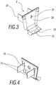
Figure 4 is a detail rear perspective view of the joint piece, represented inFigure 3 ; and -
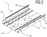
Figure 5 is a view of an individual tray. - In view of the mentioned figures, and in accordance with the adopted numeration, in said figures a preferred exemplary embodiment of the invention may be observed which comprises the parts and elements which are indicated and described in detail below.
- The joint for cable holder trays is provided for allowing trays (1) to be joined which are each formed by a sheet folded substantially in a U shape which has a base (10) and two lateral walls (11) provided at the top with a reinforcement band (12). One of the ends of the tray (1) includes a male section (13) with a predetermined length with a transversal section with smaller dimensions with respect to the rest of the sheet, the male section being free of the reinforcement band (12). The male section (13) may be coupled into an opposing end of an adjacent sheet such that in a condition where the two adjacent trays are coupled one above the other, the lateral walls (11) and the base (10) of the trays are overlapping each other in which the male section is located in the interior of the adjacent sheet in a coplanar manner. Optionally, an upper cover may be provided (not shown) for covering the interior housing defined by each tray (1).
- In order to ensure the fixing in the joint between the trays, a pair of joint pieces (2) is provided situated on the lateral walls (11), each of these being formed from a stamped metal body which is defined by two fins (20, 21) which adopt a general configuration substantially in an L shape. Each one of the two fins (20, 21) has a tab (22, 23) which is coupled by a snap-in connection or clip into respective through-holes (14, 15) present in the male section (13), the fin of the joint piece (2) that is connected to the lateral wall of the tray (1) having coupling means provided for being coupled to the lateral wall of the tray, which will be explained in greater detail below. In this embodiment, the tab (23) consists of a centered depression which is inserted manually by means of applying pressure exerted laterally until the tab (23) reaches or fits into the through-hole (15) which provides a pressure area on the two trays, thus reducing the degree of impedance, that is to say, it improves the electric continuity value between trays.
- In this way, the use of screws such as tools is not necessary for carrying out the screwing action to integrally connect two adjacent trays, especially relating to the joint of the trays at their base. In addition, the tab (22), once the trays are placed in a coupling condition, prevents the separation of both since it prevents the return movement of the male section (13) with respect to the tray to which the cited male section (13) is fixed. This is a result of the tab (22) connected to the lateral wall of the tray protruding outwards in an inclined manner with respect to the surface of the fin from which it protrudes.
- As may be seen more clearly in
Figure 4 , the coupling means consist of two foldable portions (24) which protrude from the exterior face of the fin connected to the lateral wall of the tray, such portions being capable of being folded and passing through through-holes (16) made into the lateral wall of the tray (1), as may be seen inFigure 5 . More specifically, the two foldable portions (24) extend from two opposing laterals of a section (25) which, in an assembled condition of the joint piece, are hidden and face the lateral wall (11) of the tray (1). - The details, the forms, the dimensions and other accessory elements used in obtaining the joint of the invention could be conveniently substituted for others which do not depart from the scope defined by the claims which are included below.
Claims (4)
- A system comprising a cable tray and a joint for the cable tray in which the tray (1) is formed by a sheet folded substantially in a U shape which has a base (10) and two lateral (11) walls provided with a band (12), which includes a male section (13) with a predetermined length with a transversal section with smaller dimensions with respect to the rest of the sheet, the male section (13) being free of the band (12) and being couplable into an opposing end of an adjacent sheet, such that in a coupling condition of two adjacent trays to each other, the lateral walls and the base of the trays are overlapping each other, the male section (13) being located in the interior of the adjacent sheet in a coplanar manner, the joint comprising at least one joint piece (2) characterized in that the joint piece (2) is formed from a folded body which defines two fins (20, 21) which adopt a general configuration substantially in an L shape in which each one of the two fins (20, 21) has a tab (22, 23) couplable by way of a snap-in connection in through-holes (14, 15) present on the male section (13), the fin (20) of the joint piece (2) which is connected to the lateral wall (11) of the tray (1) having coupling means provided for being coupled to the lateral wall (11) of the tray (1), and the coupling means consist of two portions capable of being folded in an assembled condition which protrude from an additional section (25) present on the exterior face of the fin connected to the lateral wall of the tray, such foldable portions being capable of being folded and passing through through-holes made in the lateral wall of the tray.
- The system according to claim 1, characterized in that the tab (22) of the joint piece connected to the lateral wall (11) of the tray (1) protrudes outwards in an inclined manner with respect to the surface of the fin (20) from which it protrudes.
- The system according to claim 1, characterized in that the tab (23) of the joint which is connected to the base of the cable tray consists of a centered depression which is inserted manually by means of applying pressure exerted laterally until the tab (23) reaches or fits into the through-hole (15).
- The system according to claim 1, characterized in that the joint piece is made of metal material.
Applications Claiming Priority (2)
| Application Number | Priority Date | Filing Date | Title |
|---|---|---|---|
| ES201530712U ES1140762Y (en) | 2015-06-17 | 2015-06-17 | UNION FOR PORTABLE TRAYS |
| PCT/ES2015/070763 WO2016203068A1 (en) | 2015-06-17 | 2015-10-22 | Cable tray coupling system |
Publications (3)
| Publication Number | Publication Date |
|---|---|
| EP3148024A1 EP3148024A1 (en) | 2017-03-29 |
| EP3148024A4 EP3148024A4 (en) | 2018-02-14 |
| EP3148024B1 true EP3148024B1 (en) | 2020-04-15 |
Family
ID=53487795
Family Applications (1)
| Application Number | Title | Priority Date | Filing Date |
|---|---|---|---|
| EP15894517.0A Active EP3148024B1 (en) | 2015-06-17 | 2015-10-22 | Cable tray coupling system |
Country Status (3)
| Country | Link |
|---|---|
| EP (1) | EP3148024B1 (en) |
| ES (2) | ES1140762Y (en) |
| WO (1) | WO2016203068A1 (en) |
Families Citing this family (3)
| Publication number | Priority date | Publication date | Assignee | Title |
|---|---|---|---|---|
| CA3140089A1 (en) | 2019-05-13 | 2020-11-19 | Eaton Intelligent Power Limited | Wireway and wireway connector for wireway system |
| ES2987886T3 (en) * | 2020-07-15 | 2024-11-18 | Basor Electric S A | Gasket for cable trays and cable tray |
| KR102635643B1 (en) * | 2023-08-17 | 2024-02-14 | 주식회사 광명엔지니어링건축사사무소 | Hanger type cable tray device for apartment house |
Family Cites Families (8)
| Publication number | Priority date | Publication date | Assignee | Title |
|---|---|---|---|---|
| DE8102851U1 (en) * | 1981-02-04 | 1982-07-22 | OBO Bettermann oHG, 5750 Menden | Cable tray as a carrier for electrical cables |
| FR2686141B1 (en) * | 1992-01-14 | 1994-04-22 | Mavil | COMBINATION OF CABLE PATH AND CONNECTION SIDES AND METHOD OF IMPLEMENTING SAID COMBINATION. |
| FR2723167B1 (en) * | 1994-07-29 | 1996-10-25 | Krieg & Zivy Ind | SLIDE FOR CABLES |
| ES2156487B1 (en) | 1997-07-02 | 2003-04-01 | Basor Electric S A | PACK FOR PORTABLE TRAYS. |
| BE1018514A3 (en) * | 2009-03-26 | 2011-02-01 | Vergokan | CONICAL CABLE JOB. |
| ES1070765Y (en) * | 2009-06-16 | 2010-06-25 | Pemsa Pequeno Material Electri | COUPLING MODULE OF PORTABLE TRAY |
| FR2948504B1 (en) * | 2009-07-27 | 2012-12-14 | Cts Cable Tray Systems Sas | LOCKING SYSTEM FOR CABLES AND CABLES PROVIDED WITH SUCH A SYSTEM |
| FR3009450B1 (en) * | 2013-07-31 | 2015-10-02 | Gewiss France Sas | CABLE PATH DEVICE AND METHOD FOR CONNECTING THE CABLE PATH DEVICE WITH A CABLE PATH TRUNK |
-
2015
- 2015-06-17 ES ES201530712U patent/ES1140762Y/en not_active Expired - Fee Related
- 2015-10-22 WO PCT/ES2015/070763 patent/WO2016203068A1/en not_active Ceased
- 2015-10-22 EP EP15894517.0A patent/EP3148024B1/en active Active
- 2015-10-22 ES ES15894517T patent/ES2797098T3/en active Active
Non-Patent Citations (1)
| Title |
|---|
| None * |
Also Published As
| Publication number | Publication date |
|---|---|
| ES1140762Y (en) | 2015-09-23 |
| EP3148024A1 (en) | 2017-03-29 |
| ES1140762U (en) | 2015-07-02 |
| WO2016203068A1 (en) | 2016-12-22 |
| EP3148024A4 (en) | 2018-02-14 |
| ES2797098T3 (en) | 2020-12-01 |
Similar Documents
| Publication | Publication Date | Title |
|---|---|---|
| USD861450S1 (en) | Electronic torque screwdriver | |
| US6132238A (en) | Connector for electrical conductors | |
| US9243723B2 (en) | Universal mounting clamp | |
| EP3148024A1 (en) | Cable tray coupling system | |
| WO2018041774A3 (en) | Conductor terminal | |
| USD797061S1 (en) | Paddle switch with externally facing electrical connector port or ports | |
| EP3159976B1 (en) | Label-holder element for electric wires | |
| US7222394B2 (en) | Bushing for metal studs and the like | |
| US9982695B2 (en) | Fitting for strut channel | |
| JP6992621B2 (en) | Connector and socket | |
| EP3941685A4 (en) | ELECTRICALLY INSULATED TOOL WITH NON-CONDUCTIVE TORQUE TRANSFER COMPONENT | |
| US3127471A (en) | Strain relief clamp | |
| JP5438508B2 (en) | Noise absorber | |
| US7150661B2 (en) | Electrical and mechanical connecting device for an electrical connection unit | |
| EP2764796A1 (en) | Slide rail assembly for use in rack system and reinforcement member thereof | |
| CN108028475A (en) | Connection equipment for conductor | |
| SE432037B (en) | ELECTRICAL INSTALLATION CONNECTION | |
| EP1717920A1 (en) | Device for supporting electrical components and wiring accessories | |
| EP2498355B1 (en) | Sheet metal tray module for channelling cables | |
| US753714A (en) | Conduit for electrical conductors. | |
| JP2018518932A5 (en) | ||
| CN104953334B (en) | Structures for holding electrical/electronic components with wires | |
| US20240388048A1 (en) | A connector | |
| JP6283950B2 (en) | Air conditioner | |
| EP2892110A1 (en) | Field-replaceable terminal block divider |
Legal Events
| Date | Code | Title | Description |
|---|---|---|---|
| STAA | Information on the status of an ep patent application or granted ep patent |
Free format text: STATUS: UNKNOWN |
|
| STAA | Information on the status of an ep patent application or granted ep patent |
Free format text: STATUS: THE INTERNATIONAL PUBLICATION HAS BEEN MADE |
|
| PUAI | Public reference made under article 153(3) epc to a published international application that has entered the european phase |
Free format text: ORIGINAL CODE: 0009012 |
|
| STAA | Information on the status of an ep patent application or granted ep patent |
Free format text: STATUS: REQUEST FOR EXAMINATION WAS MADE |
|
| 17P | Request for examination filed |
Effective date: 20161215 |
|
| AK | Designated contracting states |
Kind code of ref document: A1 Designated state(s): AL AT BE BG CH CY CZ DE DK EE ES FI FR GB GR HR HU IE IS IT LI LT LU LV MC MK MT NL NO PL PT RO RS SE SI SK SM TR |
|
| AX | Request for extension of the european patent |
Extension state: BA ME |
|
| A4 | Supplementary search report drawn up and despatched |
Effective date: 20180115 |
|
| RIC1 | Information provided on ipc code assigned before grant |
Ipc: H02G 3/06 20060101AFI20180109BHEP |
|
| RIC1 | Information provided on ipc code assigned before grant |
Ipc: H02G 3/06 20060101AFI20180423BHEP |
|
| DAV | Request for validation of the european patent (deleted) | ||
| DAX | Request for extension of the european patent (deleted) | ||
| STAA | Information on the status of an ep patent application or granted ep patent |
Free format text: STATUS: EXAMINATION IS IN PROGRESS |
|
| 17Q | First examination report despatched |
Effective date: 20190116 |
|
| GRAP | Despatch of communication of intention to grant a patent |
Free format text: ORIGINAL CODE: EPIDOSNIGR1 |
|
| STAA | Information on the status of an ep patent application or granted ep patent |
Free format text: STATUS: GRANT OF PATENT IS INTENDED |
|
| INTG | Intention to grant announced |
Effective date: 20200205 |
|
| GRAS | Grant fee paid |
Free format text: ORIGINAL CODE: EPIDOSNIGR3 |
|
| GRAA | (expected) grant |
Free format text: ORIGINAL CODE: 0009210 |
|
| STAA | Information on the status of an ep patent application or granted ep patent |
Free format text: STATUS: THE PATENT HAS BEEN GRANTED |
|
| AK | Designated contracting states |
Kind code of ref document: B1 Designated state(s): AL AT BE BG CH CY CZ DE DK EE ES FI FR GB GR HR HU IE IS IT LI LT LU LV MC MK MT NL NO PL PT RO RS SE SI SK SM TR |
|
| REG | Reference to a national code |
Ref country code: CH Ref legal event code: EP |
|
| REG | Reference to a national code |
Ref country code: DE Ref legal event code: R096 Ref document number: 602015050931 Country of ref document: DE |
|
| REG | Reference to a national code |
Ref country code: IE Ref legal event code: FG4D |
|
| REG | Reference to a national code |
Ref country code: AT Ref legal event code: REF Ref document number: 1258406 Country of ref document: AT Kind code of ref document: T Effective date: 20200515 |
|
| REG | Reference to a national code |
Ref country code: NL Ref legal event code: MP Effective date: 20200415 |
|
| REG | Reference to a national code |
Ref country code: LT Ref legal event code: MG4D |
|
| PG25 | Lapsed in a contracting state [announced via postgrant information from national office to epo] |
Ref country code: SE Free format text: LAPSE BECAUSE OF FAILURE TO SUBMIT A TRANSLATION OF THE DESCRIPTION OR TO PAY THE FEE WITHIN THE PRESCRIBED TIME-LIMIT Effective date: 20200415 Ref country code: PT Free format text: LAPSE BECAUSE OF FAILURE TO SUBMIT A TRANSLATION OF THE DESCRIPTION OR TO PAY THE FEE WITHIN THE PRESCRIBED TIME-LIMIT Effective date: 20200817 Ref country code: LT Free format text: LAPSE BECAUSE OF FAILURE TO SUBMIT A TRANSLATION OF THE DESCRIPTION OR TO PAY THE FEE WITHIN THE PRESCRIBED TIME-LIMIT Effective date: 20200415 Ref country code: NL Free format text: LAPSE BECAUSE OF FAILURE TO SUBMIT A TRANSLATION OF THE DESCRIPTION OR TO PAY THE FEE WITHIN THE PRESCRIBED TIME-LIMIT Effective date: 20200415 Ref country code: IS Free format text: LAPSE BECAUSE OF FAILURE TO SUBMIT A TRANSLATION OF THE DESCRIPTION OR TO PAY THE FEE WITHIN THE PRESCRIBED TIME-LIMIT Effective date: 20200815 Ref country code: GR Free format text: LAPSE BECAUSE OF FAILURE TO SUBMIT A TRANSLATION OF THE DESCRIPTION OR TO PAY THE FEE WITHIN THE PRESCRIBED TIME-LIMIT Effective date: 20200716 Ref country code: NO Free format text: LAPSE BECAUSE OF FAILURE TO SUBMIT A TRANSLATION OF THE DESCRIPTION OR TO PAY THE FEE WITHIN THE PRESCRIBED TIME-LIMIT Effective date: 20200715 Ref country code: FI Free format text: LAPSE BECAUSE OF FAILURE TO SUBMIT A TRANSLATION OF THE DESCRIPTION OR TO PAY THE FEE WITHIN THE PRESCRIBED TIME-LIMIT Effective date: 20200415 |
|
| REG | Reference to a national code |
Ref country code: AT Ref legal event code: MK05 Ref document number: 1258406 Country of ref document: AT Kind code of ref document: T Effective date: 20200415 |
|
| PG25 | Lapsed in a contracting state [announced via postgrant information from national office to epo] |
Ref country code: BG Free format text: LAPSE BECAUSE OF FAILURE TO SUBMIT A TRANSLATION OF THE DESCRIPTION OR TO PAY THE FEE WITHIN THE PRESCRIBED TIME-LIMIT Effective date: 20200715 Ref country code: HR Free format text: LAPSE BECAUSE OF FAILURE TO SUBMIT A TRANSLATION OF THE DESCRIPTION OR TO PAY THE FEE WITHIN THE PRESCRIBED TIME-LIMIT Effective date: 20200415 Ref country code: RS Free format text: LAPSE BECAUSE OF FAILURE TO SUBMIT A TRANSLATION OF THE DESCRIPTION OR TO PAY THE FEE WITHIN THE PRESCRIBED TIME-LIMIT Effective date: 20200415 Ref country code: LV Free format text: LAPSE BECAUSE OF FAILURE TO SUBMIT A TRANSLATION OF THE DESCRIPTION OR TO PAY THE FEE WITHIN THE PRESCRIBED TIME-LIMIT Effective date: 20200415 |
|
| REG | Reference to a national code |
Ref country code: ES Ref legal event code: FG2A Ref document number: 2797098 Country of ref document: ES Kind code of ref document: T3 Effective date: 20201201 |
|
| PG25 | Lapsed in a contracting state [announced via postgrant information from national office to epo] |
Ref country code: AL Free format text: LAPSE BECAUSE OF FAILURE TO SUBMIT A TRANSLATION OF THE DESCRIPTION OR TO PAY THE FEE WITHIN THE PRESCRIBED TIME-LIMIT Effective date: 20200415 |
|
| REG | Reference to a national code |
Ref country code: DE Ref legal event code: R097 Ref document number: 602015050931 Country of ref document: DE |
|
| PG25 | Lapsed in a contracting state [announced via postgrant information from national office to epo] |
Ref country code: RO Free format text: LAPSE BECAUSE OF FAILURE TO SUBMIT A TRANSLATION OF THE DESCRIPTION OR TO PAY THE FEE WITHIN THE PRESCRIBED TIME-LIMIT Effective date: 20200415 Ref country code: IT Free format text: LAPSE BECAUSE OF FAILURE TO SUBMIT A TRANSLATION OF THE DESCRIPTION OR TO PAY THE FEE WITHIN THE PRESCRIBED TIME-LIMIT Effective date: 20200415 Ref country code: CZ Free format text: LAPSE BECAUSE OF FAILURE TO SUBMIT A TRANSLATION OF THE DESCRIPTION OR TO PAY THE FEE WITHIN THE PRESCRIBED TIME-LIMIT Effective date: 20200415 Ref country code: AT Free format text: LAPSE BECAUSE OF FAILURE TO SUBMIT A TRANSLATION OF THE DESCRIPTION OR TO PAY THE FEE WITHIN THE PRESCRIBED TIME-LIMIT Effective date: 20200415 Ref country code: EE Free format text: LAPSE BECAUSE OF FAILURE TO SUBMIT A TRANSLATION OF THE DESCRIPTION OR TO PAY THE FEE WITHIN THE PRESCRIBED TIME-LIMIT Effective date: 20200415 Ref country code: SM Free format text: LAPSE BECAUSE OF FAILURE TO SUBMIT A TRANSLATION OF THE DESCRIPTION OR TO PAY THE FEE WITHIN THE PRESCRIBED TIME-LIMIT Effective date: 20200415 Ref country code: DK Free format text: LAPSE BECAUSE OF FAILURE TO SUBMIT A TRANSLATION OF THE DESCRIPTION OR TO PAY THE FEE WITHIN THE PRESCRIBED TIME-LIMIT Effective date: 20200415 |
|
| PLBE | No opposition filed within time limit |
Free format text: ORIGINAL CODE: 0009261 |
|
| STAA | Information on the status of an ep patent application or granted ep patent |
Free format text: STATUS: NO OPPOSITION FILED WITHIN TIME LIMIT |
|
| PG25 | Lapsed in a contracting state [announced via postgrant information from national office to epo] |
Ref country code: SK Free format text: LAPSE BECAUSE OF FAILURE TO SUBMIT A TRANSLATION OF THE DESCRIPTION OR TO PAY THE FEE WITHIN THE PRESCRIBED TIME-LIMIT Effective date: 20200415 Ref country code: PL Free format text: LAPSE BECAUSE OF FAILURE TO SUBMIT A TRANSLATION OF THE DESCRIPTION OR TO PAY THE FEE WITHIN THE PRESCRIBED TIME-LIMIT Effective date: 20200415 |
|
| 26N | No opposition filed |
Effective date: 20210118 |
|
| REG | Reference to a national code |
Ref country code: DE Ref legal event code: R119 Ref document number: 602015050931 Country of ref document: DE |
|
| PG25 | Lapsed in a contracting state [announced via postgrant information from national office to epo] |
Ref country code: SI Free format text: LAPSE BECAUSE OF FAILURE TO SUBMIT A TRANSLATION OF THE DESCRIPTION OR TO PAY THE FEE WITHIN THE PRESCRIBED TIME-LIMIT Effective date: 20200415 |
|
| REG | Reference to a national code |
Ref country code: CH Ref legal event code: PL |
|
| GBPC | Gb: european patent ceased through non-payment of renewal fee |
Effective date: 20201022 |
|
| PG25 | Lapsed in a contracting state [announced via postgrant information from national office to epo] |
Ref country code: LU Free format text: LAPSE BECAUSE OF NON-PAYMENT OF DUE FEES Effective date: 20201022 Ref country code: MC Free format text: LAPSE BECAUSE OF FAILURE TO SUBMIT A TRANSLATION OF THE DESCRIPTION OR TO PAY THE FEE WITHIN THE PRESCRIBED TIME-LIMIT Effective date: 20200415 |
|
| REG | Reference to a national code |
Ref country code: BE Ref legal event code: MM Effective date: 20201031 |
|
| PG25 | Lapsed in a contracting state [announced via postgrant information from national office to epo] |
Ref country code: FR Free format text: LAPSE BECAUSE OF NON-PAYMENT OF DUE FEES Effective date: 20201031 Ref country code: DE Free format text: LAPSE BECAUSE OF NON-PAYMENT OF DUE FEES Effective date: 20210501 |
|
| PG25 | Lapsed in a contracting state [announced via postgrant information from national office to epo] |
Ref country code: BE Free format text: LAPSE BECAUSE OF NON-PAYMENT OF DUE FEES Effective date: 20201031 Ref country code: CH Free format text: LAPSE BECAUSE OF NON-PAYMENT OF DUE FEES Effective date: 20201031 Ref country code: LI Free format text: LAPSE BECAUSE OF NON-PAYMENT OF DUE FEES Effective date: 20201031 Ref country code: GB Free format text: LAPSE BECAUSE OF NON-PAYMENT OF DUE FEES Effective date: 20201022 |
|
| PG25 | Lapsed in a contracting state [announced via postgrant information from national office to epo] |
Ref country code: IE Free format text: LAPSE BECAUSE OF NON-PAYMENT OF DUE FEES Effective date: 20201022 |
|
| PG25 | Lapsed in a contracting state [announced via postgrant information from national office to epo] |
Ref country code: TR Free format text: LAPSE BECAUSE OF FAILURE TO SUBMIT A TRANSLATION OF THE DESCRIPTION OR TO PAY THE FEE WITHIN THE PRESCRIBED TIME-LIMIT Effective date: 20200415 Ref country code: MT Free format text: LAPSE BECAUSE OF FAILURE TO SUBMIT A TRANSLATION OF THE DESCRIPTION OR TO PAY THE FEE WITHIN THE PRESCRIBED TIME-LIMIT Effective date: 20200415 Ref country code: CY Free format text: LAPSE BECAUSE OF FAILURE TO SUBMIT A TRANSLATION OF THE DESCRIPTION OR TO PAY THE FEE WITHIN THE PRESCRIBED TIME-LIMIT Effective date: 20200415 |
|
| PG25 | Lapsed in a contracting state [announced via postgrant information from national office to epo] |
Ref country code: MK Free format text: LAPSE BECAUSE OF FAILURE TO SUBMIT A TRANSLATION OF THE DESCRIPTION OR TO PAY THE FEE WITHIN THE PRESCRIBED TIME-LIMIT Effective date: 20200415 |
|
| PGFP | Annual fee paid to national office [announced via postgrant information from national office to epo] |
Ref country code: ES Payment date: 20251230 Year of fee payment: 11 |