EP3148029B1 - Fehlerschutzvorrichtungen und verfahren für stromversorgungssysteme - Google Patents
Fehlerschutzvorrichtungen und verfahren für stromversorgungssysteme Download PDFInfo
- Publication number
- EP3148029B1 EP3148029B1 EP16190395.0A EP16190395A EP3148029B1 EP 3148029 B1 EP3148029 B1 EP 3148029B1 EP 16190395 A EP16190395 A EP 16190395A EP 3148029 B1 EP3148029 B1 EP 3148029B1
- Authority
- EP
- European Patent Office
- Prior art keywords
- channel
- current
- ground fault
- protection device
- fault protection
- Prior art date
- Legal status (The legal status is an assumption and is not a legal conclusion. Google has not performed a legal analysis and makes no representation as to the accuracy of the status listed.)
- Active
Links
Images

Classifications
-
- H—ELECTRICITY
- H01—ELECTRIC ELEMENTS
- H01H—ELECTRIC SWITCHES; RELAYS; SELECTORS; EMERGENCY PROTECTIVE DEVICES
- H01H83/00—Protective switches, e.g. circuit-breaking switches, or protective relays operated by abnormal electrical conditions otherwise than solely by excess current
- H01H83/02—Protective switches, e.g. circuit-breaking switches, or protective relays operated by abnormal electrical conditions otherwise than solely by excess current operated by earth fault currents
-
- H—ELECTRICITY
- H02—GENERATION; CONVERSION OR DISTRIBUTION OF ELECTRIC POWER
- H02H—EMERGENCY PROTECTIVE CIRCUIT ARRANGEMENTS
- H02H3/00—Emergency protective circuit arrangements for automatic disconnection directly responsive to an undesired change from normal electric working condition with or without subsequent reconnection ; integrated protection
- H02H3/16—Emergency protective circuit arrangements for automatic disconnection directly responsive to an undesired change from normal electric working condition with or without subsequent reconnection ; integrated protection responsive to fault current to earth, frame or mass
-
- H—ELECTRICITY
- H02—GENERATION; CONVERSION OR DISTRIBUTION OF ELECTRIC POWER
- H02H—EMERGENCY PROTECTIVE CIRCUIT ARRANGEMENTS
- H02H3/00—Emergency protective circuit arrangements for automatic disconnection directly responsive to an undesired change from normal electric working condition with or without subsequent reconnection ; integrated protection
- H02H3/26—Emergency protective circuit arrangements for automatic disconnection directly responsive to an undesired change from normal electric working condition with or without subsequent reconnection ; integrated protection responsive to difference between voltages or between currents; responsive to phase angle between voltages or between currents
- H02H3/32—Emergency protective circuit arrangements for automatic disconnection directly responsive to an undesired change from normal electric working condition with or without subsequent reconnection ; integrated protection responsive to difference between voltages or between currents; responsive to phase angle between voltages or between currents involving comparison of the voltage or current values at corresponding points in different conductors of a single system, e.g. of currents in go and return conductors
- H02H3/33—Emergency protective circuit arrangements for automatic disconnection directly responsive to an undesired change from normal electric working condition with or without subsequent reconnection ; integrated protection responsive to difference between voltages or between currents; responsive to phase angle between voltages or between currents involving comparison of the voltage or current values at corresponding points in different conductors of a single system, e.g. of currents in go and return conductors using summation current transformers
-
- H—ELECTRICITY
- H02—GENERATION; CONVERSION OR DISTRIBUTION OF ELECTRIC POWER
- H02H—EMERGENCY PROTECTIVE CIRCUIT ARRANGEMENTS
- H02H7/00—Emergency protective circuit arrangements specially adapted for specific types of electric machines or apparatus or for sectionalised protection of cable or line systems, and effecting automatic switching in the event of an undesired change from normal working conditions
- H02H7/26—Sectionalised protection of cable or line systems, e.g. for disconnecting a section on which a short-circuit, earth fault, or arc discharge has occured
- H02H7/261—Sectionalised protection of cable or line systems, e.g. for disconnecting a section on which a short-circuit, earth fault, or arc discharge has occured involving signal transmission between at least two stations
-
- H—ELECTRICITY
- H02—GENERATION; CONVERSION OR DISTRIBUTION OF ELECTRIC POWER
- H02H—EMERGENCY PROTECTIVE CIRCUIT ARRANGEMENTS
- H02H7/00—Emergency protective circuit arrangements specially adapted for specific types of electric machines or apparatus or for sectionalised protection of cable or line systems, and effecting automatic switching in the event of an undesired change from normal working conditions
- H02H7/26—Sectionalised protection of cable or line systems, e.g. for disconnecting a section on which a short-circuit, earth fault, or arc discharge has occured
- H02H7/268—Sectionalised protection of cable or line systems, e.g. for disconnecting a section on which a short-circuit, earth fault, or arc discharge has occured for DC systems
Definitions
- the present disclosure relates to power systems, and more particular to ground fault protection devices for power systems and relates to a method of protecting such power systems from ground fault.
- Power systems commonly include alternating current (AC) power sources that supply direct current (DC) power to devices requiring DC power through power converters.
- the power converters convert AC power from the AC power into DC power that may be supplied to one or more DC-powered devices.
- the AC power may be converted into the high-voltage direct current (HVDC) power that is routed to other power converters that change the voltage of the DC power such that it is suitable the DC-powered devices.
- Electrical isolation between various power system components typically limits current leakage between the power system and ground to a few milliamps or less to prevent current leakage between power system components.
- current leakages can develop within the power system between conductors and/or energized components and ground. In vehicular power systems such leakages can cause the power system neutral-to-ground voltage differential to shift.
- Current leakages can also occur from distributed capacitance, which can result in the sympathetic or nuisance trips during power system operation. Such current leakage can influence reliability of the power system.
- a power system as defined by claim 1. A method of protecting a power system from ground faults according to claim 11.
- FIG. 1 a partial view of an exemplary embodiment of a ground fault protection device in accordance with the disclosure is shown in Fig. 1 and is designated generally by reference character 100.
- FIGs. 2 - 5 Other embodiments of ground fault protection devices and methods of protecting electrical devices from ground fault events in accordance with the disclosure, or aspects thereof, are provided in Figs. 2 - 5 , as will be described.
- the systems and methods described herein can be used for electric power distribution systems, such as in power distribution architectures for more-electric vehicles.
- Power system 10 includes a vehicle chassis 12 and a power generation and distribution system 14.
- Power generation and distribution system 14 includes a generator 16 connected to an active rectifier 32 through a first contactor 40.
- Active rectifier 32 is connected to a high-voltage direct current (HVDC) power bus 34 through a second contactor 42, and therethrough to a plurality of electrical loads, e.g. a first electrical load 18, a second electrical load 20, and a third electrical load 21, by a power management and distribution system 22.
- HVDC high-voltage direct current
- generator 16 includes an alternating current (AC) permanent magnet generator (PMG) with an A-phase winding 24, a B-phase winding 26, and a C-phase winding 28 arranged in a Y-connected stator winding arranged.
- Generator 16 has a generator neutral 30 that is isolated from vehicle chassis 12.
- A-phase winding 24, B-phase winding 26, and C-phase winding 28 are connected to active rectifier 32.
- Active rectifier 32 is configured to receive AC power from generator 16, convert the AC power into direct current (DC) power, and provide the DC power to a HVDC bus
- HVDC bus 34 is connected to power management and distribution system 22, and therethrough to aplurality of DC channels, e.g., a first DC channel 36, a second DC channel 38 and a third DC channel 39.
- the DC channels provide DC power to DC loads through a solid-state power controller (SSPC) connected to DC channel, e.g., a first SSPC 102 providing power to a first channel load, a second SSPC 104 providing power to a second channel load and a third SSPC 105 providing power to a third channel load.
- Power generation and distribution system 14 is electrically isolated from chassis 12 such that substantially no current flows from power generation and distribution system 14 to chassis 12.
- the SSPC devices are integral with a power management and distribution system 22 and may include embedded channel ground fault protection devices (shown in Fig. 3 ).
- HVDC high-voltage direct current
- G 1 showing a generator ground fault
- G 2 showing a rectifier ground fault
- G 3 showing a DC bus ground fault
- G 4 showing a ground fault on a first DC channel
- G 5 showing a ground fault on a second DC channel.
- HVDC refers to voltages carried by conductors and/or electrical components that greater than 300 volts, for example in power distribution architectures carrying voltages between 300 and 600 volts.
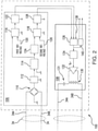
- Bus ground fault protection device 100 includes a leakage current module 106 that is optically coupled to an AC signal injection module 108. Leakage current module 106 and AC signal injection module 108 are connected to HVDC bus 34. Leakage current module 106 is configured to determine whether current leakage from HVDC bus 34 exceeds a predetermined HVDC current imbalance threshold. Upon determining that current leakage from HVDC bus 34 exceeds a predetermined current leakage threshold of HVDC bus 34, leakage current module 106 provides an optical indication to AC signal injection module 108 that current leakage from HVDC bus 34 exceeds the current leakage threshold of HVDC bus 34.
- DC channel ground fault protection devices are coupled to HVDC bus 34, e.g., DC channel ground fault protection device 150 couples to first DC channel 36 (each shown in Fig. 1 ).
- DC channel ground fault protection device 151 couples to a second DC channel 38 (each shown in Fig.
- DC channel ground fault protection device 151 couples to third DC channel 39 (each shown in Fig.1 ), receive the AC signal in DC power supplied to the DC channel, measure current imbalances in first DC channel 36 and/or second DC channel 38, and based on the measured current imbalance, determine whether to disconnect first DC channel 36 and/or second DC channel 38 from HVDC bus 34.
- Leakage current module 106 includes a wheatstone bridge 110, a voltage divider 112, and an absolute value module 114.
- Wheatstone bridge 110 is connected between a positive HVDC lead 34A and a negative HVDC lead 34B of HVDC bus 34, and is configured to current leakage within power generation and distribution system 14 by determining current imbalance at different locations within power generation and distribution system 14.
- Voltage divider 112 is connected to a center point of wheatstone bridge 110.
- Absolute value module 114 is connected to voltage divider 112, and is configured to output a voltage that corresponds (e.g. is proportional) to current leakage from HVDC bus 34 corresponding to measurements acquired from wheatstone bridge 110.
- Absolute value module 114 is connected to a first voltage comparator 116 and a second voltage comparator 118.
- First voltage comparator 116 includes a first reference voltage lead 120, and is configured to compare voltages received from absolute value module 114 and first reference voltage lead 120. Based on the comparison, first voltage comparator 116 outputs an enable signal to a first optocoupler 122, which is optically coupled to AC signal injection module 108.
- Absolute value module 114 is connected to second voltage comparator 118 through a low pass filter 124.
- Low pass filer 124 and a second reference voltage lead 126 are connected to second voltage comparator 118, which compares the voltage received with a reference voltage received through second reference voltage lead 126. Based on the comparison, second voltage comparator 118 outputs an enable signal to a second optocoupler 128, which is optically coupled to AC signal injection module 108.
- the second reference voltage received by second voltage comparator 118 through second reference voltage lead 126 is greater than the first reference voltage received by first voltage comparator 116 through first reference voltage lead 120, and corresponds to a bus current leakage threshold associated with power generation and distribution system 14 above which disconnect is warranted.
- indication of current leakage from HVDC bus 34 may be indicated by current imbalance between positive and return leads, and may be associated with ground fault.
- AC signal injection module 108 includes an isolation transformer 130, an amplifier 132, and a signal generator 134.
- An enable OR logic module 136 is connected to signal generator 134, and is configured to cause signal generator to output a fixed signal of predetermined frequency for injection through amplifier 132 and isolation transformer 130 on to DC power flowing through HVDC bus 34.
- enable OR logic module 136 includes first and second optical inputs, that are individually optically coupled to first optocoupler 122 and second optocouplers 128, and a power-up lead 138, which receives voltage when power generation and distribution system 14 is powered up for self-test purposes. When any one of the leads to enable OR logic module 136 have voltage applied, enable OR logic module 136 causes signal generator 134 to output a signal to amplifier 132.
- Amplifier 132 applies the signal to HVDC bus 34 through isolation transformer 130, which is connected to HVDC bus 34 through a secondary winding and a DC current blocking capacitor 131.
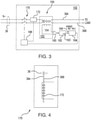
- First SSPC 102 includes a DC channel ground fault protection device 150.
- DC channel ground fault protection device 150 includes a common mode current sensor 152 with a sense inductor 154, a channel positive lead inductor 156, and channel return lead inductor 158.
- Channel positive lead inductor 156 is connected in series with a DC channel positive lead 36A of first DC channel 36.
- Channel return lead inductor 158 is connected in series with DC channel return lead 36B of first DC channel 36.
- Sense inductor 154 is electromagnetically coupled to both DC channel positive lead 36A and DC channel return lead 36B.
- Common mode current sensor 152 is sensitive to current imbalance conditions, which in turn may indicate ground fault events (occurrences).
- Sense inductor 154 of common mode current sensor 152 is connected to an amplifier 160.
- Amplifier 160 is arranged to apply an amplifier output to a synchronous detector module 162, which converts the amplifier output to a sense voltage corresponding to a current induced in sense inductor 154 by current imbalance between channel positive lead inductor and channel return lead inductor.
- a ground fault event is initially detected by leakage current module 106 of ground fault protection device 100, and AC signal is placed on HVDC bus 34 to identify the solid-state power converter (i.e. first SSPC 102, second SSPC 104, etc.) responsible for the ground fault event.
- the AC signal is selected at the output of synchronous detector module 162, which includes a narrowband selective filter 163.
- Synchronous detector module 162 applies the voltage to a comparator 164, which compares the voltage to a channel reference voltage received through a channel reference voltage reference lead 166.
- comparator 164 Based on the comparison of the sense voltage and the reference voltage, comparator 164 provides a disconnect signal to a disconnect controller 168 operatively associated with a disconnect switch connected in series with first DC channel 36. This causes DC channel ground fault protection device 150 to disconnect first SSPC 102 and loads connected thereto from first DC channel 36.
- a DC current sensor 172 is also connected in series with first DC channel 36 and is operatively associated with disconnect controller 168 to disconnect first SSPC 102 from first DC channel 36 in the event that overcurrent is detected, such as through incorporation of OR logic into disconnect controller 168.
- second SSPC 104 may also include a DC channel ground fault protection device 150 that provides corresponding ground fault protection to second DC channel 38 in response to the AC signal applied to HVDC power provided by HVDC bus 34.
- common mode current sensor 170 is shown according to another embodiment.
- Common mode current sensor 170 is similar to common mode current sensor 152 with the difference that, instead of three inductors (i.e. channel positive lead inductor 156, channel return lead inductor 158, and sense inductor 154, each shown in Fig. 3 ), common mode current sensor 170 includes a DC current sensor 172, e.g. a coil, extending about both DC channel positive lead 36A and DC channel return lead 36B and electromagnetically coupled thereto.
- DC current sensor 172 e.g. a coil
- AC signal injection module 108 also includes a delay logic module 140.
- Delay logic module 140 is operatively connected to first contactor 11 of active rectifier 32 (shown in Fig. 1 ) through a second contractor 42.
- delay logic module 140 opens a disconnect switch of first contactor 11 and/or second contactor 13. As will be appreciated, opening the disconnect switch disconnects HVDC bus 34 from either generator 16 or from both generator 16 (shown in Fig. 1 ) and active rectifier 32 (shown in Fig.
- the delay interval provides an escalation in response to the recognition of current imbalance on HVDC bus 34 wherein, in the event that no imbalance is located on a DC channel connected to HVDC bus 34, HVDC bus 34 is disconnected from its power source.
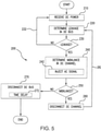
- Method 200 includes receiving HVDC power, e.g., through HVDC bus 34 (shown in Fig. 1 ), as shown with box 210.
- Current leakage from the HVDC bus is determined, such as by using HVDC bus ground fault protection device 100 (shown in Fig. 1 ), as shown with box 220.
- the determined current leakage from the HVDC bus is compared against a current leakage threshold of HVDC bus, as shown with box 230, and if the determined current leakage is below the threshold, monitoring continues as shown with arrow 232.
- current imbalance in one or more DC channels is determined, as shown with box 240. This may include causing DC channel ground fault protection devices connected to the DC to determine current imbalance in the respective channels, as shown with box 242.
- determining current imbalance in a given DC channel can include measuring and comparing current flow through positive and return leads of DC channels that are connected to the DC bus. Current imbalance in a given DC channel is compared to a DC channel current imbalance threshold, as shown in box 250.
- the DC channel is disconnected, as shown with box 260. Imbalance in the DC bus is thereafter checked, as shown with arrow 262, to determine whether disconnecting the DC channel returned current leakage from the HVDC bus to below current leakage threshold of the HVDC bus.
- the HVDC bus is disconnected from the power source, as shown with box 270. It is contemplated that the DC bus be disconnected from the power source after tolling of a time delay interval, as shown with box 272.
- the time delay is (a) triggered by the application AC signal to DC power flowing through the HVDC bus, and (b) is of sufficient duration to allow the DC channels connected to the DC bus to determine current imbalance within the respective DC channels, but is sufficiently short to prevent damage to power system components.
- ground fault protection provides for power systems with superior properties including improved ground fault protection.
- electronic components experiencing ground faults may be isolated from electronic components not experiencing ground faults.
- ground fault detection may be improved by reducing (or eliminating) sympathetic tripping and/or nuisance tripping.
- the size of the common mode current sensor may be reduced.
Landscapes
- Engineering & Computer Science (AREA)
- Power Engineering (AREA)
- Emergency Protection Circuit Devices (AREA)
Claims (13)
- Stromversorgungssystem, umfassend:einen DC-Kanal (36), der mit einem Hochspannungsgleichstrombus (34) ,Abkürzung HVDC-Bus;eine HVDC-Bus-Erdkurzschlussschutzvorrichtung (100), die mit dem HVDC-Bus verbunden ist; undeine DC-Kanal-Erdkurzschlussschutzvorrichtung (150), die mit dem DC-Kanal verbunden ist,wobei die HVDC-Bus-Erdkurzschlussschutzvorrichtung durch den DC-Kanal betriebswirksam mit der DC-Kanal-Erdkurzschlussschutzvorrichtung verbunden ist und dazu konfiguriert ist, die DC-Kanal- Erdkurzschlussschutzvorrichtung dazu zu veranlassen, den DC-Kanal von dem HVDC-Bus zu trennen basierend auf einem Erkennen eines Stromlecks in dem HVDC-Bus durch Verwenden der HVDC-Bus-Erdkurzschlussschutzvorrichtung und dann ein Erkennen eines aktuellen Ungleichgewichts in dem DC-Kanal durch Verwenden der DC-Kanal-Erdkurzschlussschutzvorrichtung;dadurch gekennzeichnet, dass die DC-Kanal-Erdkurzschlussschutzvorrichtung einen Gleichtaktstromsensor (152) beinhaltet, der empfindlich auf ein Stromungleichgewicht ist und an den DC-Kanal gekoppelt ist, und wobei die DC-Kanal-Erdkurzschlussschutzvorrichtung ferner Folgendes beinhaltet:einen Verstärker (160), der mit dem Gleichtaktstromsensor verbunden ist;einen Synchrondetektor (162), der mit dem Verstärker verbunden ist;einen Komparator (164), der mit dem Synchrondetektor und einer Kanalreferenzspannungsleitung verbunden ist; undwobei der Komparator dazu konfiguriert ist, ein Trennsignal basierend auf einem Vergleich des spannungsentsprechenden Stromungleichgewichts in dem DC-Kanal und einer Referenzspannung auszugeben, die durch die Kanalreferenzspannungsleitung empfangen wird.
- Stromversorgungssystem nach Anspruch 1, wobei die HVDC-Bus-Erdkurzschlussschutzvorrichtung ein Leckstrommodul (106) beinhaltet, das optisch an ein AC-Signal-Einspeisemodul (108) gekoppelt ist.
- Stromversorgungssystem nach Anspruch 2, wobei das AC-Signal-Einspeisemodul einen Isolationstransformator (130) beinhaltet, der mit einem DC-Stromsperrkondensator (131) in Reihe geschaltet ist, wobei der DC-Stromsperrkondensator zwischen einer Plus- und Minusleitung des HVDC-Busses geschaltet ist.
- Stromversorgungssystem nach Anspruch 2, wobei das Leckstrommodul eine Wheatstone-Brücke (110) beinhaltet, die zwischen einer Plus- und Minusleitung des HVDC-Busses geschaltet ist.
- Stromversorgungssystem nach einem der vorstehenden Ansprüche, ferner beinhaltend eine Stromquelle und einen Trennschalter, der mit dem HVDC-Bus in Reihe geschaltet ist, und bei dem der Trennschalter vorzugsweise mit der HVDC-Bus-Erdkurzschlussschutzvorrichtung betriebswirksam verbunden ist.
- Stromversorgungssystem nach Anspruch 5, wobei die Stromquelle eine Wechselstromquelle (AC-Quelle) (16) mit Permanentmagnetgenerator beinhaltet, oder wobei die Stromquelle einen aktiven Gleichrichter beinhaltet.
- Stromversorgungssystem nach einem der vorstehenden Ansprüche, wobei die HVDC-Bus-Erdkurzschlussschutzvorrichtung ein Verzögerungsmodul (140) beinhaltet, das dazu konfiguriert ist, den HVDC-Bus nach einem vorgegebenen Verzögerungsintervall von einer Stromquelle zu trennen.
- Stromversorgungssystem nach einem der vorstehenden Ansprüche, wobei der DC-Kanal einen Festkörper-Stromrichter (102) beinhaltet, wobei die DC-Kanal-Erdkurzschlussschutzvorrichtung betriebswirksam mit dem Festkörper-Stromrichter verbunden ist.
- Stromversorgungssystem nach Anspruch 1, wobei die DC-Kanal-Erdkurzschlussschutzvorrichtung Folgendes beinhaltet:einen Trennschalter, der mit dem DC-Kanal verbunden ist;einen DC-Stromsensor (172), der mit dem DC-Kanal verbunden ist;undeine Trennsteuerung (168), die mit dem DC-Stromsensor, dem Gleichtaktsensor und dem Trennschalter verbunden ist, um den DC-Kanal basierend auf Eingängen von dem DC-Stromsensor und dem Gleichtaktsensor zu trennen.
- Stromversorgungssystem nach Anspruch 1, wobei der Gleichtaktstromsensor eine Erfassungswicklung (154) beinhaltet, die elektromagnetisch mit der Plus- und Minusleitung des DC-Kanals verbunden ist.
- Verfahren zum Schutz eines Stromversorgungssystems vor Erdkurzschlüssen, umfassend:Empfangen von Gleichstrom, Abkürzung DC, an einem HVDC-Bus;Bestimmen eines Leckstroms von dem HVDC-Bus unter Verwendung einer HVDC-Bus-Erdkurzschlussschutzvorrichtung;Bestimmen eines Stromungleichgewichts in einem DC-Kanal, der mit dem HVDC-Bus verbunden ist, unter Verwendung einer DC-Kanal-Erdkurzschlussschutzvorrichtung, wenn der HVDC-Bus-Leckstrom einen HVDC-Bus-Leckstromschwellenwert überschreitet; undTrennen des DC-Kanals von dem HVDC-Bus, wenn das Stromungleichgewicht auf dem DC-Kanal einen DC-Kanal-Stromungleichgewichtsschwellenwert überschreitet; unddadurch gekennzeichnet, dass die DC-Kanal-Erdkurzschlussschutzvorrichtung einen Gleichtaktstromsensor (152) beinhaltet, an den DC-Kanal gekoppelt ist, und wobei die DC-Kanal-Erdkurzschlussschutzvorrichtung ferner Folgendes beinhaltet:einen Verstärker (160), der mit dem Gleichtaktstromsensor verbunden ist;einen Synchrondetektor (162), der mit dem Verstärker verbunden ist;einen Komparator (164), der mit dem Synchrondetektor und einer Kanalreferenzspannungsleitung verbunden ist; undwobei der Komparator ein Trennsignal basierend auf einem Vergleich des spannungsentsprechenden Stromungleichgewichts in dem DC-Kanal und einer Referenzspannung ausgibt, die durch die Kanalreferenzspannungsleitung empfangen wird.
- Verfahren nach Anspruch 11, wobei ein Bestimmen des Stromungleichgewichts in dem DC-Kanal das Einspeisen eines Wechselstromsignals (AC-Signals) in die DC-Stromversorgung beinhaltet, oder wobei ein Bestimmen eines Stromungleichgewichts in dem DC-Kanal ein Bestimmen des Stromungleichgewichts beinhaltet, wenn ein AC-Stromsignal in der dem DC-Kanal zugeführten DC-Stromversorgung vorhanden ist.
- Verfahren nach Anspruch 11, ferner beinhaltend ein Trennen des HVDC-Busses von einer Stromquelle, wenn der Leckstrom aus dem HVDC den HVDC-Bus-Leckstromschwellenwert für ein vorbestimmtes Zeitintervall überschreitet.
Applications Claiming Priority (1)
| Application Number | Priority Date | Filing Date | Title |
|---|---|---|---|
| US14/862,833 US9859085B2 (en) | 2015-09-23 | 2015-09-23 | Fault protection devices and methods for power systems |
Publications (2)
| Publication Number | Publication Date |
|---|---|
| EP3148029A1 EP3148029A1 (de) | 2017-03-29 |
| EP3148029B1 true EP3148029B1 (de) | 2022-03-23 |
Family
ID=56990354
Family Applications (1)
| Application Number | Title | Priority Date | Filing Date |
|---|---|---|---|
| EP16190395.0A Active EP3148029B1 (de) | 2015-09-23 | 2016-09-23 | Fehlerschutzvorrichtungen und verfahren für stromversorgungssysteme |
Country Status (2)
| Country | Link |
|---|---|
| US (1) | US9859085B2 (de) |
| EP (1) | EP3148029B1 (de) |
Families Citing this family (16)
| Publication number | Priority date | Publication date | Assignee | Title |
|---|---|---|---|---|
| CN106374978A (zh) * | 2016-08-29 | 2017-02-01 | 阳光电源股份有限公司 | 电力载波信号耦合电路及通信系统 |
| DE102017215006A1 (de) * | 2017-08-28 | 2019-02-28 | Siemens Aktiengesellschaft | Erkennen eines Fehlers in einem Gleichstromübertragungssystem |
| US10976762B2 (en) * | 2018-10-26 | 2021-04-13 | Rolls-Royce North American Technologies, Inc. | Control of an electrical power system responsive to sensing a ground fault |
| CN109921391B (zh) | 2019-03-14 | 2021-08-24 | 中国电力科学研究院有限公司 | 一种基于电流突变量的直流输电线路保护的启动方法及系统 |
| US10946865B1 (en) * | 2019-10-14 | 2021-03-16 | GM Global Technology Operations LLC | Fault isolation, prognosis, and mitigation for vehicle component electrical power circuit |
| EP3820031B1 (de) | 2019-11-05 | 2025-02-26 | Hamilton Sundstrand Corporation | Leistungsvorrichtungsgesundheitsüberwachung unter verwendung einer brückenanordnung |
| EP3893346A1 (de) | 2020-04-09 | 2021-10-13 | HS Elektronik Systeme GmbH | Elektrische sicherheitsschaltung |
| CN111983377A (zh) * | 2020-07-14 | 2020-11-24 | 国网江苏省电力有限公司电力科学研究院 | 高压直流输电线路故障判定方法和装置 |
| WO2022055863A1 (en) * | 2020-09-08 | 2022-03-17 | Commscope Technologies Llc | Apparatuses and methods for averting human harm due to high voltage powerlines |
| US12081014B2 (en) | 2020-12-23 | 2024-09-03 | Hamilton Sundstrand Corporation | Fault clearing in midpoint grounded systems |
| DE102022116360A1 (de) | 2021-07-08 | 2023-01-12 | Cummins Power Generation Ip, Inc. | Systeme und verfahren zum bereitstellen von erdschlussschutz bei gleichstromleistungsversorgung von motorbauteilen |
| CN115097231B (zh) * | 2022-05-25 | 2024-08-06 | 国网安徽省电力有限公司电力科学研究院 | 一种中性线直通的漏电保护器不停电测试装置及方法 |
| US12519412B2 (en) | 2022-06-09 | 2026-01-06 | Hamilton Sundstrand Corporation | Common mode current feed fault protection |
| US12352825B2 (en) | 2022-06-09 | 2025-07-08 | Hamilton Sundstrand Corporation | Common mode voltage feed fault protection |
| US12123905B2 (en) * | 2022-06-09 | 2024-10-22 | Hamilton Sundstrand Corporation | Common mode current feed fault protection |
| US12445044B2 (en) * | 2023-08-10 | 2025-10-14 | Chroma Ate Inc. | Two-way AC power conversion device |
Family Cites Families (23)
| Publication number | Priority date | Publication date | Assignee | Title |
|---|---|---|---|---|
| US4837519A (en) | 1985-09-06 | 1989-06-06 | Southern California Edison Company | Fault detection |
| US20040136125A1 (en) | 1998-09-16 | 2004-07-15 | Nemir David C. | Leakage current detection based upon load sharing conductors |
| US6856137B2 (en) | 2002-02-19 | 2005-02-15 | Bae Systems Controls Inc. | Ground fault detection system and method |
| US6678132B1 (en) | 2002-09-06 | 2004-01-13 | Bae Systems Controls, Inc. | Ground fault detection system |
| GB0509045D0 (en) | 2005-05-04 | 2005-06-08 | Deepstream Technologies Ltd | Circuit protection device and test facility to simulate a fault condition |
| US7459914B2 (en) | 2006-10-31 | 2008-12-02 | Caterpillar Inc. | Systems and methods for electrical leakage detection |
| US7626396B2 (en) | 2006-12-27 | 2009-12-01 | Caterpillar Inc. | Systems and methods for electrical leakage detection and compensation |
| US7649360B2 (en) | 2008-01-18 | 2010-01-19 | Gm Global Technology Operations, Inc. | Apparatus and systems for common mode voltage-based AC fault detection, verification and/or identification |
| US8022710B2 (en) | 2008-01-18 | 2011-09-20 | GM Global Technology Operations LLC | Methods for common mode voltage-based AC fault detection, verification and/or identification |
| US7978446B2 (en) | 2008-02-29 | 2011-07-12 | Caterpillar Inc. | High voltage ground fault detection system |
| US8288954B2 (en) * | 2008-12-07 | 2012-10-16 | Cirrus Logic, Inc. | Primary-side based control of secondary-side current for a transformer |
| US8278934B2 (en) | 2009-02-13 | 2012-10-02 | Bae Systems Controls Inc. | Robust AC chassis fault detection using PWM sideband harmonics |
| US8040139B2 (en) | 2009-02-16 | 2011-10-18 | Maxim Integrated Products, Inc. | Fault detection method for detecting leakage paths between power sources and chassis |
| JP5401250B2 (ja) | 2009-10-06 | 2014-01-29 | 日立オートモティブシステムズ株式会社 | 地絡検出装置 |
| US8598897B2 (en) | 2010-01-26 | 2013-12-03 | Maxim Integrated Products, Inc. | Isolation monitoring system and method utilizing a variable emulated inductance |
| WO2012010193A1 (en) | 2010-07-19 | 2012-01-26 | Abb Technology Ag | Device and method for detecting a ground fault |
| US8710850B2 (en) | 2010-12-27 | 2014-04-29 | Renault S.A.S. | System and method for detecting an earth ground fault of an external power supply connected to a vehicle |
| EP2566010A1 (de) * | 2011-08-31 | 2013-03-06 | Nokia Siemens Networks Oy | Verfahren, Vorrichtung und System zur Stromsteuerung |
| US9274158B2 (en) | 2012-11-15 | 2016-03-01 | Ford Global Technologies, Llc | Hybrid/electrical vehicle HV AC system leakage and ground fault detection |
| CN104037929B (zh) * | 2013-03-06 | 2017-06-27 | 华为技术有限公司 | 一种供电方法及装置 |
| US9099936B2 (en) * | 2013-03-14 | 2015-08-04 | General Electric Company | High voltage direct current (HVDC) converter system and method of operating the same |
| US9270119B2 (en) * | 2013-05-24 | 2016-02-23 | Eaton Corporation | High voltage direct current transmission and distribution system |
| US9692223B2 (en) | 2013-10-31 | 2017-06-27 | General Electric Company | Power distribution systems and methods of testing a power distribution system |
-
2015
- 2015-09-23 US US14/862,833 patent/US9859085B2/en active Active
-
2016
- 2016-09-23 EP EP16190395.0A patent/EP3148029B1/de active Active
Also Published As
| Publication number | Publication date |
|---|---|
| US20170084414A1 (en) | 2017-03-23 |
| US9859085B2 (en) | 2018-01-02 |
| EP3148029A1 (de) | 2017-03-29 |
Similar Documents
| Publication | Publication Date | Title |
|---|---|---|
| EP3148029B1 (de) | Fehlerschutzvorrichtungen und verfahren für stromversorgungssysteme | |
| AU2008280932B2 (en) | Charging monitor | |
| RU2542494C2 (ru) | Устройство и способ для детектирования короткого замыкания на землю | |
| US4412169A (en) | Circuit for detecting and indicating faults and operating anomalies in a system for recharging electric accumulators | |
| US9007735B2 (en) | Fault detection, isolation, location and reconnection systems and methods | |
| US8842401B2 (en) | Protection system for an electrical power network | |
| CN102395891B (zh) | 用于监测it网隔离的方法和设备 | |
| US10569895B2 (en) | Systems, methods, and devices for bipolar high voltage direct current ground fault detection | |
| US20090167314A1 (en) | Method and Device for Detecting Ground Faults in a Supply Cable | |
| KR20140041622A (ko) | 절연 결함의 검출 | |
| EP2772770B1 (de) | Rotorerdungsfehlerschutz für eine doppelt eingespeiste Induktionsmaschine mit elektrisch variabler Drehzahl | |
| US20090015973A1 (en) | Increased Voltage Vehicle Electrical System | |
| US4173774A (en) | Parallel AC electrical system with differential protection immune to high current through faults | |
| EP2196812A1 (de) | Überwachungsvorrichtung zur Erfassung von Erdschlüssen | |
| CN112564058B (zh) | 具有监控和诊断系统的、电连接的ac充电器 | |
| KR20260028841A (ko) | 개별 고장 전류가 모니터링되는 주 전압 출력 지점 및 중앙 고장 전류 의존형 스위치 오프를 갖는 차량 측 교류 발생기 | |
| EP2651026B1 (de) | Automatische Fehlerisolierungsmethodologie | |
| KR20240136396A (ko) | 충전 스테이션 서지 보호 조치를 고려한 모니터링식 충전 방법 | |
| US11588322B2 (en) | Fault detection for a solid state power converter | |
| RU2662449C1 (ru) | Устройство для резервирования защит тяговых подстанций | |
| RU2239269C1 (ru) | Устройство для защиты от замыканий на землю и контроля сопротивления изоляции электроустановки переменного тока | |
| KR102927515B1 (ko) | It계통의 누전 검출 장치 및 방법 | |
| SU907669A1 (ru) | Устройство дл контрол изол ции и защиты обмотки статора блочного генератора от замыканий на землю | |
| SU1705901A1 (ru) | Устройство дл защиты цепи возбуждени генератора | |
| KR20210119637A (ko) | 누전 및 감전보호 기능을 구비한 콘센트 |
Legal Events
| Date | Code | Title | Description |
|---|---|---|---|
| PUAI | Public reference made under article 153(3) epc to a published international application that has entered the european phase |
Free format text: ORIGINAL CODE: 0009012 |
|
| STAA | Information on the status of an ep patent application or granted ep patent |
Free format text: STATUS: THE APPLICATION HAS BEEN PUBLISHED |
|
| AK | Designated contracting states |
Kind code of ref document: A1 Designated state(s): AL AT BE BG CH CY CZ DE DK EE ES FI FR GB GR HR HU IE IS IT LI LT LU LV MC MK MT NL NO PL PT RO RS SE SI SK SM TR |
|
| AX | Request for extension of the european patent |
Extension state: BA ME |
|
| STAA | Information on the status of an ep patent application or granted ep patent |
Free format text: STATUS: REQUEST FOR EXAMINATION WAS MADE |
|
| 17P | Request for examination filed |
Effective date: 20170927 |
|
| RBV | Designated contracting states (corrected) |
Designated state(s): AL AT BE BG CH CY CZ DE DK EE ES FI FR GB GR HR HU IE IS IT LI LT LU LV MC MK MT NL NO PL PT RO RS SE SI SK SM TR |
|
| RIC1 | Information provided on ipc code assigned before grant |
Ipc: H02H 3/33 20060101AFI20210224BHEP Ipc: H02H 3/16 20060101ALI20210224BHEP Ipc: H02H 7/26 20060101ALI20210224BHEP |
|
| GRAP | Despatch of communication of intention to grant a patent |
Free format text: ORIGINAL CODE: EPIDOSNIGR1 |
|
| STAA | Information on the status of an ep patent application or granted ep patent |
Free format text: STATUS: GRANT OF PATENT IS INTENDED |
|
| INTG | Intention to grant announced |
Effective date: 20210421 |
|
| GRAJ | Information related to disapproval of communication of intention to grant by the applicant or resumption of examination proceedings by the epo deleted |
Free format text: ORIGINAL CODE: EPIDOSDIGR1 |
|
| STAA | Information on the status of an ep patent application or granted ep patent |
Free format text: STATUS: REQUEST FOR EXAMINATION WAS MADE |
|
| INTC | Intention to grant announced (deleted) | ||
| GRAP | Despatch of communication of intention to grant a patent |
Free format text: ORIGINAL CODE: EPIDOSNIGR1 |
|
| STAA | Information on the status of an ep patent application or granted ep patent |
Free format text: STATUS: GRANT OF PATENT IS INTENDED |
|
| GRAJ | Information related to disapproval of communication of intention to grant by the applicant or resumption of examination proceedings by the epo deleted |
Free format text: ORIGINAL CODE: EPIDOSDIGR1 |
|
| GRAP | Despatch of communication of intention to grant a patent |
Free format text: ORIGINAL CODE: EPIDOSNIGR1 |
|
| INTG | Intention to grant announced |
Effective date: 20211014 |
|
| INTG | Intention to grant announced |
Effective date: 20211027 |
|
| GRAS | Grant fee paid |
Free format text: ORIGINAL CODE: EPIDOSNIGR3 |
|
| GRAA | (expected) grant |
Free format text: ORIGINAL CODE: 0009210 |
|
| STAA | Information on the status of an ep patent application or granted ep patent |
Free format text: STATUS: THE PATENT HAS BEEN GRANTED |
|
| AK | Designated contracting states |
Kind code of ref document: B1 Designated state(s): AL AT BE BG CH CY CZ DE DK EE ES FI FR GB GR HR HU IE IS IT LI LT LU LV MC MK MT NL NO PL PT RO RS SE SI SK SM TR |
|
| REG | Reference to a national code |
Ref country code: GB Ref legal event code: FG4D |
|
| REG | Reference to a national code |
Ref country code: CH Ref legal event code: EP |
|
| REG | Reference to a national code |
Ref country code: IE Ref legal event code: FG4D |
|
| REG | Reference to a national code |
Ref country code: DE Ref legal event code: R096 Ref document number: 602016070212 Country of ref document: DE |
|
| REG | Reference to a national code |
Ref country code: AT Ref legal event code: REF Ref document number: 1478104 Country of ref document: AT Kind code of ref document: T Effective date: 20220415 |
|
| REG | Reference to a national code |
Ref country code: LT Ref legal event code: MG9D |
|
| REG | Reference to a national code |
Ref country code: NL Ref legal event code: MP Effective date: 20220323 |
|
| PG25 | Lapsed in a contracting state [announced via postgrant information from national office to epo] |
Ref country code: SE Free format text: LAPSE BECAUSE OF FAILURE TO SUBMIT A TRANSLATION OF THE DESCRIPTION OR TO PAY THE FEE WITHIN THE PRESCRIBED TIME-LIMIT Effective date: 20220323 Ref country code: RS Free format text: LAPSE BECAUSE OF FAILURE TO SUBMIT A TRANSLATION OF THE DESCRIPTION OR TO PAY THE FEE WITHIN THE PRESCRIBED TIME-LIMIT Effective date: 20220323 Ref country code: NO Free format text: LAPSE BECAUSE OF FAILURE TO SUBMIT A TRANSLATION OF THE DESCRIPTION OR TO PAY THE FEE WITHIN THE PRESCRIBED TIME-LIMIT Effective date: 20220623 Ref country code: LT Free format text: LAPSE BECAUSE OF FAILURE TO SUBMIT A TRANSLATION OF THE DESCRIPTION OR TO PAY THE FEE WITHIN THE PRESCRIBED TIME-LIMIT Effective date: 20220323 Ref country code: HR Free format text: LAPSE BECAUSE OF FAILURE TO SUBMIT A TRANSLATION OF THE DESCRIPTION OR TO PAY THE FEE WITHIN THE PRESCRIBED TIME-LIMIT Effective date: 20220323 Ref country code: BG Free format text: LAPSE BECAUSE OF FAILURE TO SUBMIT A TRANSLATION OF THE DESCRIPTION OR TO PAY THE FEE WITHIN THE PRESCRIBED TIME-LIMIT Effective date: 20220623 |
|
| REG | Reference to a national code |
Ref country code: AT Ref legal event code: MK05 Ref document number: 1478104 Country of ref document: AT Kind code of ref document: T Effective date: 20220323 |
|
| PG25 | Lapsed in a contracting state [announced via postgrant information from national office to epo] |
Ref country code: LV Free format text: LAPSE BECAUSE OF FAILURE TO SUBMIT A TRANSLATION OF THE DESCRIPTION OR TO PAY THE FEE WITHIN THE PRESCRIBED TIME-LIMIT Effective date: 20220323 Ref country code: GR Free format text: LAPSE BECAUSE OF FAILURE TO SUBMIT A TRANSLATION OF THE DESCRIPTION OR TO PAY THE FEE WITHIN THE PRESCRIBED TIME-LIMIT Effective date: 20220624 Ref country code: FI Free format text: LAPSE BECAUSE OF FAILURE TO SUBMIT A TRANSLATION OF THE DESCRIPTION OR TO PAY THE FEE WITHIN THE PRESCRIBED TIME-LIMIT Effective date: 20220323 |
|
| PG25 | Lapsed in a contracting state [announced via postgrant information from national office to epo] |
Ref country code: NL Free format text: LAPSE BECAUSE OF FAILURE TO SUBMIT A TRANSLATION OF THE DESCRIPTION OR TO PAY THE FEE WITHIN THE PRESCRIBED TIME-LIMIT Effective date: 20220323 |
|
| PG25 | Lapsed in a contracting state [announced via postgrant information from national office to epo] |
Ref country code: SM Free format text: LAPSE BECAUSE OF FAILURE TO SUBMIT A TRANSLATION OF THE DESCRIPTION OR TO PAY THE FEE WITHIN THE PRESCRIBED TIME-LIMIT Effective date: 20220323 Ref country code: SK Free format text: LAPSE BECAUSE OF FAILURE TO SUBMIT A TRANSLATION OF THE DESCRIPTION OR TO PAY THE FEE WITHIN THE PRESCRIBED TIME-LIMIT Effective date: 20220323 Ref country code: RO Free format text: LAPSE BECAUSE OF FAILURE TO SUBMIT A TRANSLATION OF THE DESCRIPTION OR TO PAY THE FEE WITHIN THE PRESCRIBED TIME-LIMIT Effective date: 20220323 Ref country code: PT Free format text: LAPSE BECAUSE OF FAILURE TO SUBMIT A TRANSLATION OF THE DESCRIPTION OR TO PAY THE FEE WITHIN THE PRESCRIBED TIME-LIMIT Effective date: 20220725 Ref country code: ES Free format text: LAPSE BECAUSE OF FAILURE TO SUBMIT A TRANSLATION OF THE DESCRIPTION OR TO PAY THE FEE WITHIN THE PRESCRIBED TIME-LIMIT Effective date: 20220323 Ref country code: EE Free format text: LAPSE BECAUSE OF FAILURE TO SUBMIT A TRANSLATION OF THE DESCRIPTION OR TO PAY THE FEE WITHIN THE PRESCRIBED TIME-LIMIT Effective date: 20220323 Ref country code: CZ Free format text: LAPSE BECAUSE OF FAILURE TO SUBMIT A TRANSLATION OF THE DESCRIPTION OR TO PAY THE FEE WITHIN THE PRESCRIBED TIME-LIMIT Effective date: 20220323 Ref country code: AT Free format text: LAPSE BECAUSE OF FAILURE TO SUBMIT A TRANSLATION OF THE DESCRIPTION OR TO PAY THE FEE WITHIN THE PRESCRIBED TIME-LIMIT Effective date: 20220323 |
|
| PG25 | Lapsed in a contracting state [announced via postgrant information from national office to epo] |
Ref country code: PL Free format text: LAPSE BECAUSE OF FAILURE TO SUBMIT A TRANSLATION OF THE DESCRIPTION OR TO PAY THE FEE WITHIN THE PRESCRIBED TIME-LIMIT Effective date: 20220323 Ref country code: IS Free format text: LAPSE BECAUSE OF FAILURE TO SUBMIT A TRANSLATION OF THE DESCRIPTION OR TO PAY THE FEE WITHIN THE PRESCRIBED TIME-LIMIT Effective date: 20220723 Ref country code: AL Free format text: LAPSE BECAUSE OF FAILURE TO SUBMIT A TRANSLATION OF THE DESCRIPTION OR TO PAY THE FEE WITHIN THE PRESCRIBED TIME-LIMIT Effective date: 20220323 |
|
| REG | Reference to a national code |
Ref country code: DE Ref legal event code: R097 Ref document number: 602016070212 Country of ref document: DE |
|
| PLBE | No opposition filed within time limit |
Free format text: ORIGINAL CODE: 0009261 |
|
| STAA | Information on the status of an ep patent application or granted ep patent |
Free format text: STATUS: NO OPPOSITION FILED WITHIN TIME LIMIT |
|
| PG25 | Lapsed in a contracting state [announced via postgrant information from national office to epo] |
Ref country code: DK Free format text: LAPSE BECAUSE OF FAILURE TO SUBMIT A TRANSLATION OF THE DESCRIPTION OR TO PAY THE FEE WITHIN THE PRESCRIBED TIME-LIMIT Effective date: 20220323 |
|
| 26N | No opposition filed |
Effective date: 20230102 |
|
| PG25 | Lapsed in a contracting state [announced via postgrant information from national office to epo] |
Ref country code: MC Free format text: LAPSE BECAUSE OF FAILURE TO SUBMIT A TRANSLATION OF THE DESCRIPTION OR TO PAY THE FEE WITHIN THE PRESCRIBED TIME-LIMIT Effective date: 20220323 |
|
| REG | Reference to a national code |
Ref country code: CH Ref legal event code: PL |
|
| REG | Reference to a national code |
Ref country code: BE Ref legal event code: MM Effective date: 20220930 |
|
| PG25 | Lapsed in a contracting state [announced via postgrant information from national office to epo] |
Ref country code: SI Free format text: LAPSE BECAUSE OF FAILURE TO SUBMIT A TRANSLATION OF THE DESCRIPTION OR TO PAY THE FEE WITHIN THE PRESCRIBED TIME-LIMIT Effective date: 20220323 |
|
| P01 | Opt-out of the competence of the unified patent court (upc) registered |
Effective date: 20230522 |
|
| PG25 | Lapsed in a contracting state [announced via postgrant information from national office to epo] |
Ref country code: LU Free format text: LAPSE BECAUSE OF NON-PAYMENT OF DUE FEES Effective date: 20220923 |
|
| PG25 | Lapsed in a contracting state [announced via postgrant information from national office to epo] |
Ref country code: LI Free format text: LAPSE BECAUSE OF NON-PAYMENT OF DUE FEES Effective date: 20220930 Ref country code: IT Free format text: LAPSE BECAUSE OF FAILURE TO SUBMIT A TRANSLATION OF THE DESCRIPTION OR TO PAY THE FEE WITHIN THE PRESCRIBED TIME-LIMIT Effective date: 20220323 Ref country code: IE Free format text: LAPSE BECAUSE OF NON-PAYMENT OF DUE FEES Effective date: 20220923 Ref country code: CH Free format text: LAPSE BECAUSE OF NON-PAYMENT OF DUE FEES Effective date: 20220930 |
|
| PG25 | Lapsed in a contracting state [announced via postgrant information from national office to epo] |
Ref country code: BE Free format text: LAPSE BECAUSE OF NON-PAYMENT OF DUE FEES Effective date: 20220930 |
|
| PG25 | Lapsed in a contracting state [announced via postgrant information from national office to epo] |
Ref country code: HU Free format text: LAPSE BECAUSE OF FAILURE TO SUBMIT A TRANSLATION OF THE DESCRIPTION OR TO PAY THE FEE WITHIN THE PRESCRIBED TIME-LIMIT; INVALID AB INITIO Effective date: 20160923 |
|
| PG25 | Lapsed in a contracting state [announced via postgrant information from national office to epo] |
Ref country code: CY Free format text: LAPSE BECAUSE OF FAILURE TO SUBMIT A TRANSLATION OF THE DESCRIPTION OR TO PAY THE FEE WITHIN THE PRESCRIBED TIME-LIMIT Effective date: 20220323 |
|
| PG25 | Lapsed in a contracting state [announced via postgrant information from national office to epo] |
Ref country code: MK Free format text: LAPSE BECAUSE OF FAILURE TO SUBMIT A TRANSLATION OF THE DESCRIPTION OR TO PAY THE FEE WITHIN THE PRESCRIBED TIME-LIMIT Effective date: 20220323 |
|
| PG25 | Lapsed in a contracting state [announced via postgrant information from national office to epo] |
Ref country code: TR Free format text: LAPSE BECAUSE OF FAILURE TO SUBMIT A TRANSLATION OF THE DESCRIPTION OR TO PAY THE FEE WITHIN THE PRESCRIBED TIME-LIMIT Effective date: 20220323 |
|
| PG25 | Lapsed in a contracting state [announced via postgrant information from national office to epo] |
Ref country code: MT Free format text: LAPSE BECAUSE OF FAILURE TO SUBMIT A TRANSLATION OF THE DESCRIPTION OR TO PAY THE FEE WITHIN THE PRESCRIBED TIME-LIMIT Effective date: 20220323 |
|
| PGFP | Annual fee paid to national office [announced via postgrant information from national office to epo] |
Ref country code: DE Payment date: 20250820 Year of fee payment: 10 |
|
| PGFP | Annual fee paid to national office [announced via postgrant information from national office to epo] |
Ref country code: GB Payment date: 20250827 Year of fee payment: 10 |
|
| PGFP | Annual fee paid to national office [announced via postgrant information from national office to epo] |
Ref country code: FR Payment date: 20250821 Year of fee payment: 10 |