EP3148032B1 - Stromversorgungssystem für eine anordnung von parallel angeschlossenen lasten an einen bus mit kontinuierlicher stromversorgung - Google Patents
Stromversorgungssystem für eine anordnung von parallel angeschlossenen lasten an einen bus mit kontinuierlicher stromversorgung Download PDFInfo
- Publication number
- EP3148032B1 EP3148032B1 EP15306514.9A EP15306514A EP3148032B1 EP 3148032 B1 EP3148032 B1 EP 3148032B1 EP 15306514 A EP15306514 A EP 15306514A EP 3148032 B1 EP3148032 B1 EP 3148032B1
- Authority
- EP
- European Patent Office
- Prior art keywords
- power supply
- bus
- power
- loads
- supply system
- Prior art date
- Legal status (The legal status is an assumption and is not a legal conclusion. Google has not performed a legal analysis and makes no representation as to the accuracy of the status listed.)
- Active
Links
Images


Classifications
-
- H—ELECTRICITY
- H02—GENERATION; CONVERSION OR DISTRIBUTION OF ELECTRIC POWER
- H02M—APPARATUS FOR CONVERSION BETWEEN AC AND AC, BETWEEN AC AND DC, OR BETWEEN DC AND DC, AND FOR USE WITH MAINS OR SIMILAR POWER SUPPLY SYSTEMS; CONVERSION OF DC OR AC INPUT POWER INTO SURGE OUTPUT POWER; CONTROL OR REGULATION THEREOF
- H02M1/00—Details of apparatus for conversion
- H02M1/44—Circuits or arrangements for compensating for electromagnetic interference in converters or inverters
-
- H—ELECTRICITY
- H02—GENERATION; CONVERSION OR DISTRIBUTION OF ELECTRIC POWER
- H02H—EMERGENCY PROTECTIVE CIRCUIT ARRANGEMENTS
- H02H7/00—Emergency protective circuit arrangements specially adapted for specific types of electric machines or apparatus or for sectionalised protection of cable or line systems, and effecting automatic switching in the event of an undesired change from normal working conditions
- H02H7/26—Sectionalised protection of cable or line systems, e.g. for disconnecting a section on which a short-circuit, earth fault, or arc discharge has occured
- H02H7/268—Sectionalised protection of cable or line systems, e.g. for disconnecting a section on which a short-circuit, earth fault, or arc discharge has occured for DC systems
-
- H—ELECTRICITY
- H02—GENERATION; CONVERSION OR DISTRIBUTION OF ELECTRIC POWER
- H02H—EMERGENCY PROTECTIVE CIRCUIT ARRANGEMENTS
- H02H7/00—Emergency protective circuit arrangements specially adapted for specific types of electric machines or apparatus or for sectionalised protection of cable or line systems, and effecting automatic switching in the event of an undesired change from normal working conditions
- H02H7/22—Emergency protective circuit arrangements specially adapted for specific types of electric machines or apparatus or for sectionalised protection of cable or line systems, and effecting automatic switching in the event of an undesired change from normal working conditions for distribution gear, e.g. bus-bar systems; for switching devices
-
- H—ELECTRICITY
- H02—GENERATION; CONVERSION OR DISTRIBUTION OF ELECTRIC POWER
- H02J—ELECTRIC POWER NETWORKS; CIRCUIT ARRANGEMENTS OR SYSTEMS FOR SUPPLYING OR DISTRIBUTING ELECTRIC POWER; SYSTEMS FOR STORING ELECTRIC ENERGY
- H02J3/00—Circuit arrangements for AC mains or AC distribution networks
- H02J3/36—Arrangements for transfer of electric power between AC networks via high-voltage DC [HVDC] links; Arrangements for transfer of electric power between generators and networks via HVDC links
-
- H—ELECTRICITY
- H02—GENERATION; CONVERSION OR DISTRIBUTION OF ELECTRIC POWER
- H02M—APPARATUS FOR CONVERSION BETWEEN AC AND AC, BETWEEN AC AND DC, OR BETWEEN DC AND DC, AND FOR USE WITH MAINS OR SIMILAR POWER SUPPLY SYSTEMS; CONVERSION OF DC OR AC INPUT POWER INTO SURGE OUTPUT POWER; CONTROL OR REGULATION THEREOF
- H02M7/00—Conversion of AC power input into DC power output; Conversion of DC power input into AC power output
- H02M7/42—Conversion of DC power input into AC power output without possibility of reversal
- H02M7/44—Conversion of DC power input into AC power output without possibility of reversal by static converters
-
- H—ELECTRICITY
- H02—GENERATION; CONVERSION OR DISTRIBUTION OF ELECTRIC POWER
- H02J—ELECTRIC POWER NETWORKS; CIRCUIT ARRANGEMENTS OR SYSTEMS FOR SUPPLYING OR DISTRIBUTING ELECTRIC POWER; SYSTEMS FOR STORING ELECTRIC ENERGY
- H02J3/00—Circuit arrangements for AC mains or AC distribution networks
- H02J3/36—Arrangements for transfer of electric power between AC networks via high-voltage DC [HVDC] links; Arrangements for transfer of electric power between generators and networks via HVDC links
- H02J2003/365—Reducing harmonics or oscillations in HVDC
-
- Y—GENERAL TAGGING OF NEW TECHNOLOGICAL DEVELOPMENTS; GENERAL TAGGING OF CROSS-SECTIONAL TECHNOLOGIES SPANNING OVER SEVERAL SECTIONS OF THE IPC; TECHNICAL SUBJECTS COVERED BY FORMER USPC CROSS-REFERENCE ART COLLECTIONS [XRACs] AND DIGESTS
- Y02—TECHNOLOGIES OR APPLICATIONS FOR MITIGATION OR ADAPTATION AGAINST CLIMATE CHANGE
- Y02E—REDUCTION OF GREENHOUSE GAS [GHG] EMISSIONS, RELATED TO ENERGY GENERATION, TRANSMISSION OR DISTRIBUTION
- Y02E60/00—Enabling technologies; Technologies with a potential or indirect contribution to GHG emissions mitigation
- Y02E60/60—Arrangements for transfer of electric power between AC networks or generators via a high voltage DC link [HVCD]
Definitions
- the present invention relates to electric charge supply systems intended in particular, but not exclusively, for submarine applications.
- It relates more particularly to a system for supplying loads powered in parallel from a common DC power supply bus.
- the feeds can be of various kinds and be constituted for example by AC motors powered by power lines connected in parallel to the DC bus via a DC / AC converter.
- the converter constitutes an inverter which can for example be made from switching cells which can be controlled by pulse width modulation.
- the length of the DC side feed line extending between the DC bus and the converter, and the length of the AC side feed line between the converter and the load can be relatively large and vary significantly from one power line to another.
- the loads for example electric motors, may have different powers.
- the electrical loads connected to the parallel supply lines are likely to include power electronics components that can generate homopolar signals that propagate in the DC bus and to the other power lines.
- a system for supplying an ac load from an alternating network which comprises a rectifier comprising controllable electronic switches for converting an alternating current supplied by the electrical network into a direct current and a control device electronic switches capable of limiting the absolute value of the voltage between the electrical ground and a phase of the alternating current delivered to a load in the presence of an overvoltage in the load.
- the object of the invention is to propose a system for supplying a set of charges connected in parallel capable of preventing the circulation of disturbances appearing. in a supply line of one of the loads and to prevent these disturbances from circulating in the other loads.
- the decoupling and damping means further comprise at least one connection capacity to the ground of the power bus.
- the decoupling and damping means Depending on the configuration of the decoupling and damping means, a reduction of the isolation stresses of the sensitive components (such as the motors, for example) by decoupling the supply lines, as well as a reduction and amortization of the homopolar currents circulating in the lines.
- a resistor is connected in parallel to the inductor.
- the supply system further comprises protection means acting in the event of a fault on a portion of the supply system.
- the protection means comprise a set of non-return diodes arranged on the supply lines so as to prevent a flow of current to the power supply bus.
- the protection means also preferably comprise a circuit breaker with electronic switching components controlled by a control system from the value of the current flowing in said portion of the supply system.
- An electromechanical switch can also be activated in the event of a fault on said portion of the protection system.
- the power supply lines comprise a DC / AC converter supplying said loads.
- FIG. 1 there is shown an example of implementation of a feed system of a set of loads.
- the power supply system comprises a DC BUS supply bus to which are connected a set of supply lines L1,..., Ln ensuring the supply of the loads themselves.
- the bus is a DCDC and MVDC power supply bus.
- the feeds are here constituted by AC motors.
- the motors are powered by the power supply lines via DC / AC converters.
- the loads and in particular the converters, are capable of generating voltages or homopolar currents which can cause the appearance of high voltages which may be harmful for the means of isolating the supply lines, the converters and engines.
- Z b1 and Z b2 respectively represent the equivalent impedances between the system (converter, load including the alternating portions of the supply lines and the impedances of the motors) and the earth
- Z a represents the equivalent impedance between the bus and the earth, continuous side
- Vzs 1 and Vzs 2 represent the homopolar voltage generated by the converters of the two supply lines
- V b1 and V b2 represent the voltage across the impedances Z b1 and Z b2 .
- the equivalent circuit is very dependent on the value of its parameters. For example, if Z b2 is negligible in front of Z a and Z b1 , the equivalent circuit becomes that of the figure 3 .
- V b1 V ZS2 - V zs1
- the voltage at the insulation of the motor can reach the sum of the zero sequence voltages Vzs1 and Vzs2.
- the DC bus is connected to the ground by means of a capacitor C.
- This capacitance will preferably be chosen so that its value is greater than Z b1 and Z b2 so that to minimize the interactions between the supply lines and to prevent homopolar signals from being added to the DC bus.
- the power supply system is preferably provided with decoupling and damping means, on each power supply line, comprising one or more common mode inductors Lh and one or more capacitors C connecting the DC bus to ground . Thanks to this arrangement, the voltage in the loads generated by the homopolar signals is reduced. It has been found that such an embodiment is particularly suitable for submarine applications.
- Figures 7a, 7b , 7c and 7d the electrical circuit and the structure of a noise filtering inductance produced by the zero sequence signals in the differential mode supply system ( Figures 7a and 7b ) and in common mode ( Figures 7c and 7d ).
- the inductance is made from two windings 1 and 2 coiled or fed in opposite directions around a core 3.
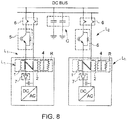
- the common bus DC BUS is recognized as well as the supply lines L1 and L2, here two in number for the sake of clarity, and the common mode decoupling and damping circuit comprising two capacitors C and the inductors Lh with the primary windings 1 and 2 and secondary 4 and the resistance R in parallel.
- the power system is completed by protection means.
- protection means comprise, for each line, a circuit breaker 5 with electronic components, here IGBT (for "Insulated Gate Bipolar Transistor", in English) controlled by a control circuit (not shown) from the value of the current flowing in the line provided by a suitable measurement sensor (not shown).
- IGBT Insulated Gate Bipolar Transistor
- the control circuit controls the opening of the power component.
- such a protection stage is particularly effective insofar as it is able to act very quickly to isolate a defective circuit portion.
- it may be insufficiently robust to the extent that it may itself be defective.
- the protection means comprise, for each line, an isolation means comprising an electromechanical or electromagnetic switch 6, for example an advantageously motorized switch, which may be longer to open but which presents improved insulation insofar as the opening of the circuit is carried out here mechanically.
- the protection means are completed by a non-return diode 7 preventing the flow of current from a converter or, in general, a defective charge to the common bus.
- step I With reference to the figure 9 when a short circuit appears on a line between the protection means 5 and the DC / AC converter, the DC / AC converter is stopped by opening its IGBT transistors (step I).
- phase II it causes the quick opening of the circuit breaker 5 to open the branch of the defective circuit and prevent the current of the short circuit flows to the DC bus and to the other loads.
- the anti-return diodes 7 prevent the flow of current from the converter of the defective line and that the capacitors of the other DC / AC converters are discharged in the defective power line.
- next phase III it causes the opening of the electromechanical switch 6 to mechanically isolate the defective circuit portion and safely allow the implementation of maintenance operations on this line.
Landscapes
- Engineering & Computer Science (AREA)
- Power Engineering (AREA)
- Physics & Mathematics (AREA)
- Electromagnetism (AREA)
- Inverter Devices (AREA)
- Direct Current Feeding And Distribution (AREA)
Claims (7)
- Versorgungssystem einer Gruppe von Lasten, das einen Gleichstrom-Versorgungsbus (DC BUS) und eine Gruppe von Versorgungsleitungen enthält, die parallel an den Versorgungsbus angeschlossen sind und die Versorgung der Lasten gewährleisten, dadurch gekennzeichnet, dass es Entkopplungs- und Dämpfungseinrichtungen (Lh, C) aufweist, die die Nullsignale reduzieren können, die bei der Versorgung der Lasten im Versorgungssystem zirkulieren, wobei die Entkopplungs- und Dämpfungseinrichtungen auf jeder Versorgungsleitung eine oder mehrere Drosselspulen (Lh), die in Reihe mit einem Wandler auf der Gleichstromseite angeordnet sind, und einem oder mehreren Kondensatoren (C) enthalten, die den Gleichstrombus mit der Masse verbinden.
- Versorgungssystem nach Anspruch 1, das einen Widerstand (R) enthält, der parallel an die Drosselspule angeschlossen ist.
- Versorgungssystem nach einem der Ansprüche 1 bis 2, das außerdem Schutzeinrichtungen (5, 6, 7) enthält, die im Fall einer Störung auf einen Abschnitt des Versorgungssystems einwirken.
- Versorgungssystem nach Anspruch 3, wobei die Schutzeinrichtungen eine Gruppe von Antirücklaufdioden (7) enthalten, die auf den Versorgungsleitungen angeordnet sind, um ein Fließen des Stroms zum Versorgungsbus zu verhindern.
- Versorgungssystem nach einem der Ansprüche 3 und 4, wobei die Schutzeinrichtungen einen Unterbrecher (5) mit elektronischen Schaltbauteilen aufweisen, der von einem Steuersystem ausgehend vom Wert des in dem Abschnitt des Versorgungssystems fließenden Stroms gesteuert wird.
- System nach einem der Ansprüche 3 bis 5, wobei die Schutzeinrichtungen einen elektromechanischen Schalter (6) aufweisen, der im Fall einer Störung in dem Abschnitt des Schutzsystems aktiviert wird.
- System nach einem der Ansprüche 1 bis 6, wobei die Versorgungsleitungen einen Stromwechselrichter enthalten, der die Lasten versorgt.
Priority Applications (3)
| Application Number | Priority Date | Filing Date | Title |
|---|---|---|---|
| EP15306514.9A EP3148032B1 (de) | 2015-09-28 | 2015-09-28 | Stromversorgungssystem für eine anordnung von parallel angeschlossenen lasten an einen bus mit kontinuierlicher stromversorgung |
| US15/762,566 US10972000B2 (en) | 2015-09-28 | 2016-09-26 | Supply system to a set of loads connected in parallel to a direct current supply bus |
| PCT/GB2016/052983 WO2017055817A1 (en) | 2015-09-28 | 2016-09-26 | Supply system for a plurality of loads connected in parallel to a direct current supply bus |
Applications Claiming Priority (1)
| Application Number | Priority Date | Filing Date | Title |
|---|---|---|---|
| EP15306514.9A EP3148032B1 (de) | 2015-09-28 | 2015-09-28 | Stromversorgungssystem für eine anordnung von parallel angeschlossenen lasten an einen bus mit kontinuierlicher stromversorgung |
Publications (2)
| Publication Number | Publication Date |
|---|---|
| EP3148032A1 EP3148032A1 (de) | 2017-03-29 |
| EP3148032B1 true EP3148032B1 (de) | 2018-03-28 |
Family
ID=54291215
Family Applications (1)
| Application Number | Title | Priority Date | Filing Date |
|---|---|---|---|
| EP15306514.9A Active EP3148032B1 (de) | 2015-09-28 | 2015-09-28 | Stromversorgungssystem für eine anordnung von parallel angeschlossenen lasten an einen bus mit kontinuierlicher stromversorgung |
Country Status (3)
| Country | Link |
|---|---|
| US (1) | US10972000B2 (de) |
| EP (1) | EP3148032B1 (de) |
| WO (1) | WO2017055817A1 (de) |
Families Citing this family (3)
| Publication number | Priority date | Publication date | Assignee | Title |
|---|---|---|---|---|
| CN107508262B (zh) * | 2017-08-22 | 2019-05-28 | 云南电网有限责任公司电力科学研究院 | 一种极保护电压采集回路及换流器零序过压保护方法 |
| US20190368315A1 (en) * | 2018-06-05 | 2019-12-05 | Saudi Arabian Oil Company | Power supply for offshore equipment and operations |
| CN113067375A (zh) * | 2021-03-26 | 2021-07-02 | 南华大学 | 交直流混合配电网广义综合负荷建模方法及模拟系统 |
Family Cites Families (12)
| Publication number | Priority date | Publication date | Assignee | Title |
|---|---|---|---|---|
| US6469485B2 (en) * | 2000-07-07 | 2002-10-22 | Honeywell International Inc. | Active filter and method for suppressing current harmonics |
| US8446037B2 (en) * | 2009-12-04 | 2013-05-21 | Kevin R. Williams | Energy storage system for peak-shaving of drilling rig power usage |
| FR2963509B1 (fr) * | 2010-07-29 | 2013-07-26 | Converteam Technology Ltd | Systeme d'alimentation d'une charge en courant alternatif a partir d'un reseau alternatif sans presence d'un transformateur entre le reseau et le systeme d'alimentation, et chaine d'entrainement comprenant un tel systeme |
| DE112011104777T5 (de) * | 2011-03-31 | 2013-10-31 | Mitsubishi Electric Corporation | Wechselstrommotor-Antriebsvorrichtung |
| US9083233B2 (en) * | 2011-10-05 | 2015-07-14 | General Electric Company | Dynamic break and distortion filter |
| DK2634885T3 (en) | 2012-02-29 | 2015-11-23 | Abb Technology Ltd | DC power system with system protection features |
| US9789973B2 (en) * | 2012-04-05 | 2017-10-17 | Hamilton Sundstrand Corporation | Power interruption bridge circuit |
| WO2014037583A2 (en) | 2012-09-10 | 2014-03-13 | Abb Technology Ag | Power distribution system for autonomous facilities |
| US9270119B2 (en) | 2013-05-24 | 2016-02-23 | Eaton Corporation | High voltage direct current transmission and distribution system |
| US9627862B2 (en) | 2013-12-26 | 2017-04-18 | General Electric Company | Methods and systems for subsea direct current power distribution |
| EP3197042B1 (de) * | 2014-09-16 | 2021-10-27 | Mitsubishi Electric Corporation | Windenergieerzeugungssystem |
| US9621101B2 (en) * | 2014-12-09 | 2017-04-11 | Johnson Controls Technology Company | Electromagnetic compatibility filter |
-
2015
- 2015-09-28 EP EP15306514.9A patent/EP3148032B1/de active Active
-
2016
- 2016-09-26 US US15/762,566 patent/US10972000B2/en active Active
- 2016-09-26 WO PCT/GB2016/052983 patent/WO2017055817A1/en not_active Ceased
Non-Patent Citations (1)
| Title |
|---|
| None * |
Also Published As
| Publication number | Publication date |
|---|---|
| WO2017055817A1 (en) | 2017-04-06 |
| US20180278155A1 (en) | 2018-09-27 |
| US10972000B2 (en) | 2021-04-06 |
| EP3148032A1 (de) | 2017-03-29 |
Similar Documents
| Publication | Publication Date | Title |
|---|---|---|
| EP2267880B1 (de) | Leistungswandler mit einem aus normalerweise geschlossenenTransistoren bestehenden Gleichrichter | |
| EP3105845B1 (de) | Gleichspannungsversorgungssystem zur vorladung eines glättungskondensators vor der speisung einer last | |
| EP3208909B1 (de) | System zur verteilung von gemischter elektrischer energie auf gleichstrom und wechselstrom zur stromversorgung von verbrauchern mit variabler frequenz und verbrauchern mit konstanter frequenz | |
| EP3148032B1 (de) | Stromversorgungssystem für eine anordnung von parallel angeschlossenen lasten an einen bus mit kontinuierlicher stromversorgung | |
| EP2677645B1 (de) | Ladungseinspeisungssystem, das einen mit einem Netz verbundenen Stromrichter umfasst sowie einen parallel zum Stromrichter geschalteten Transformator, um den Nullstrom zu begrenzen, und Antriebskette, die ein solches System umfasst | |
| EP2008357B1 (de) | Schaltnetzwerk zur reihenimplementierung von igbt-transistoren | |
| EP3255774A1 (de) | System zur umwandlung von elektrischer energie, die aus einem netz geliefert wird, und umwandlungsverfahren mittels eines solchen umwandlungssystems | |
| EP2413485B1 (de) | System zur Einspeisung einer Wechselstromladung aus einem Wechselstromnetz ohne Transformator zwischen dem Netz und dem Einspeisesystem sowie ein Antrieb, der ein solches System umfasst | |
| FR2955217A1 (fr) | Systeme d'alimentation d'un element, parmi un rotor et un stator d'une machine electrique, et procede de commande d'un tel systeme | |
| FR2947245A1 (fr) | Systeme et procede d'alimentation electrique d'un aeronef | |
| WO2020136333A1 (fr) | Protection contre les surtensions d'un système de génération d'énergie électrique à vitesse variable et fréquence constante | |
| FR2921211A1 (fr) | Systeme de redressement actif ameliore a correction du facteur de puissance. | |
| EP3657677A1 (de) | Stromversorgungsschaltkreis für steuerschaltungen von schaltern | |
| WO2012084389A2 (fr) | Convertisseur de puissance équipé en sortie d'un dispositif de filtrage | |
| EP2638632B1 (de) | Stromversorgungsschaltung für ein flugzeug mit einer asynchronmaschine | |
| EP3799671B1 (de) | System mit einer leistungsflusssteuervorrichtung zur steuerung der verteilung von strömen in einem stromnetz und mittel zum schutz dieser vorrichtung | |
| EP1964252B1 (de) | Rotierende elektrische maschine mit entkoppelten phasen | |
| EP3270515B1 (de) | Extrem schneller hochspannungsschalter | |
| EP4078755B1 (de) | Gleichspannungswandler mit einem schutzschalter | |
| EP2293422B1 (de) | Wandler eines Gleichstroms in einen anderen Gleichstrom mit Verschachtelung der Steuersignale und Einspeisungssystem, das einen solchen Wandler umfasst | |
| WO2012084572A2 (fr) | Convertisseur de puissance ac/dc a facteur de puissance et thdi ameliores | |
| FR3143235A1 (fr) | Procede de protection de convertisseurs contre les court-circuits aval | |
| FR3015146A1 (fr) | Systemes et procedes pour fournir un apport de courant auxiliaire dans des convertisseurs haute tension | |
| FR3158204A1 (fr) | Elimination de défaut dans les systèmes électriques avec signal injecté ou amplification de tension | |
| EP4651353A1 (de) | Vorrichtung zur steuerung der vorladung einer speicherkapazität und zur fehlererkennung in einer gleichstromschaltung |
Legal Events
| Date | Code | Title | Description |
|---|---|---|---|
| PUAI | Public reference made under article 153(3) epc to a published international application that has entered the european phase |
Free format text: ORIGINAL CODE: 0009012 |
|
| AK | Designated contracting states |
Kind code of ref document: A1 Designated state(s): AL AT BE BG CH CY CZ DE DK EE ES FI FR GB GR HR HU IE IS IT LI LT LU LV MC MK MT NL NO PL PT RO RS SE SI SK SM TR |
|
| AX | Request for extension of the european patent |
Extension state: BA ME |
|
| 17P | Request for examination filed |
Effective date: 20170901 |
|
| RIC1 | Information provided on ipc code assigned before grant |
Ipc: H02J 3/36 20060101ALI20170919BHEP Ipc: H02J 1/10 20060101AFI20170919BHEP Ipc: H02H 7/26 20060101ALI20170919BHEP |
|
| GRAP | Despatch of communication of intention to grant a patent |
Free format text: ORIGINAL CODE: EPIDOSNIGR1 |
|
| INTG | Intention to grant announced |
Effective date: 20171115 |
|
| GRAS | Grant fee paid |
Free format text: ORIGINAL CODE: EPIDOSNIGR3 |
|
| GRAA | (expected) grant |
Free format text: ORIGINAL CODE: 0009210 |
|
| AK | Designated contracting states |
Kind code of ref document: B1 Designated state(s): AL AT BE BG CH CY CZ DE DK EE ES FI FR GB GR HR HU IE IS IT LI LT LU LV MC MK MT NL NO PL PT RO RS SE SI SK SM TR |
|
| REG | Reference to a national code |
Ref country code: GB Ref legal event code: FG4D Free format text: NOT ENGLISH |
|
| REG | Reference to a national code |
Ref country code: CH Ref legal event code: EP |
|
| REG | Reference to a national code |
Ref country code: AT Ref legal event code: REF Ref document number: 984229 Country of ref document: AT Kind code of ref document: T Effective date: 20180415 |
|
| REG | Reference to a national code |
Ref country code: IE Ref legal event code: FG4D Free format text: LANGUAGE OF EP DOCUMENT: FRENCH |
|
| REG | Reference to a national code |
Ref country code: DE Ref legal event code: R096 Ref document number: 602015009292 Country of ref document: DE |
|
| PG25 | Lapsed in a contracting state [announced via postgrant information from national office to epo] |
Ref country code: LT Free format text: LAPSE BECAUSE OF FAILURE TO SUBMIT A TRANSLATION OF THE DESCRIPTION OR TO PAY THE FEE WITHIN THE PRESCRIBED TIME-LIMIT Effective date: 20180328 Ref country code: HR Free format text: LAPSE BECAUSE OF FAILURE TO SUBMIT A TRANSLATION OF THE DESCRIPTION OR TO PAY THE FEE WITHIN THE PRESCRIBED TIME-LIMIT Effective date: 20180328 Ref country code: NO Free format text: LAPSE BECAUSE OF FAILURE TO SUBMIT A TRANSLATION OF THE DESCRIPTION OR TO PAY THE FEE WITHIN THE PRESCRIBED TIME-LIMIT Effective date: 20180628 Ref country code: FI Free format text: LAPSE BECAUSE OF FAILURE TO SUBMIT A TRANSLATION OF THE DESCRIPTION OR TO PAY THE FEE WITHIN THE PRESCRIBED TIME-LIMIT Effective date: 20180328 |
|
| REG | Reference to a national code |
Ref country code: NL Ref legal event code: MP Effective date: 20180328 |
|
| REG | Reference to a national code |
Ref country code: LT Ref legal event code: MG4D |
|
| REG | Reference to a national code |
Ref country code: FR Ref legal event code: PLFP Year of fee payment: 4 |
|
| PG25 | Lapsed in a contracting state [announced via postgrant information from national office to epo] |
Ref country code: BG Free format text: LAPSE BECAUSE OF FAILURE TO SUBMIT A TRANSLATION OF THE DESCRIPTION OR TO PAY THE FEE WITHIN THE PRESCRIBED TIME-LIMIT Effective date: 20180628 Ref country code: GR Free format text: LAPSE BECAUSE OF FAILURE TO SUBMIT A TRANSLATION OF THE DESCRIPTION OR TO PAY THE FEE WITHIN THE PRESCRIBED TIME-LIMIT Effective date: 20180629 Ref country code: SE Free format text: LAPSE BECAUSE OF FAILURE TO SUBMIT A TRANSLATION OF THE DESCRIPTION OR TO PAY THE FEE WITHIN THE PRESCRIBED TIME-LIMIT Effective date: 20180328 Ref country code: LV Free format text: LAPSE BECAUSE OF FAILURE TO SUBMIT A TRANSLATION OF THE DESCRIPTION OR TO PAY THE FEE WITHIN THE PRESCRIBED TIME-LIMIT Effective date: 20180328 Ref country code: RS Free format text: LAPSE BECAUSE OF FAILURE TO SUBMIT A TRANSLATION OF THE DESCRIPTION OR TO PAY THE FEE WITHIN THE PRESCRIBED TIME-LIMIT Effective date: 20180328 |
|
| PG25 | Lapsed in a contracting state [announced via postgrant information from national office to epo] |
Ref country code: MT Free format text: LAPSE BECAUSE OF FAILURE TO SUBMIT A TRANSLATION OF THE DESCRIPTION OR TO PAY THE FEE WITHIN THE PRESCRIBED TIME-LIMIT Effective date: 20180328 |
|
| PG25 | Lapsed in a contracting state [announced via postgrant information from national office to epo] |
Ref country code: NL Free format text: LAPSE BECAUSE OF FAILURE TO SUBMIT A TRANSLATION OF THE DESCRIPTION OR TO PAY THE FEE WITHIN THE PRESCRIBED TIME-LIMIT Effective date: 20180328 Ref country code: PL Free format text: LAPSE BECAUSE OF FAILURE TO SUBMIT A TRANSLATION OF THE DESCRIPTION OR TO PAY THE FEE WITHIN THE PRESCRIBED TIME-LIMIT Effective date: 20180328 Ref country code: AL Free format text: LAPSE BECAUSE OF FAILURE TO SUBMIT A TRANSLATION OF THE DESCRIPTION OR TO PAY THE FEE WITHIN THE PRESCRIBED TIME-LIMIT Effective date: 20180328 Ref country code: ES Free format text: LAPSE BECAUSE OF FAILURE TO SUBMIT A TRANSLATION OF THE DESCRIPTION OR TO PAY THE FEE WITHIN THE PRESCRIBED TIME-LIMIT Effective date: 20180328 Ref country code: RO Free format text: LAPSE BECAUSE OF FAILURE TO SUBMIT A TRANSLATION OF THE DESCRIPTION OR TO PAY THE FEE WITHIN THE PRESCRIBED TIME-LIMIT Effective date: 20180328 Ref country code: IT Free format text: LAPSE BECAUSE OF FAILURE TO SUBMIT A TRANSLATION OF THE DESCRIPTION OR TO PAY THE FEE WITHIN THE PRESCRIBED TIME-LIMIT Effective date: 20180328 Ref country code: EE Free format text: LAPSE BECAUSE OF FAILURE TO SUBMIT A TRANSLATION OF THE DESCRIPTION OR TO PAY THE FEE WITHIN THE PRESCRIBED TIME-LIMIT Effective date: 20180328 |
|
| PG25 | Lapsed in a contracting state [announced via postgrant information from national office to epo] |
Ref country code: CZ Free format text: LAPSE BECAUSE OF FAILURE TO SUBMIT A TRANSLATION OF THE DESCRIPTION OR TO PAY THE FEE WITHIN THE PRESCRIBED TIME-LIMIT Effective date: 20180328 Ref country code: SM Free format text: LAPSE BECAUSE OF FAILURE TO SUBMIT A TRANSLATION OF THE DESCRIPTION OR TO PAY THE FEE WITHIN THE PRESCRIBED TIME-LIMIT Effective date: 20180328 Ref country code: SK Free format text: LAPSE BECAUSE OF FAILURE TO SUBMIT A TRANSLATION OF THE DESCRIPTION OR TO PAY THE FEE WITHIN THE PRESCRIBED TIME-LIMIT Effective date: 20180328 |
|
| REG | Reference to a national code |
Ref country code: AT Ref legal event code: MK05 Ref document number: 984229 Country of ref document: AT Kind code of ref document: T Effective date: 20180328 |
|
| PG25 | Lapsed in a contracting state [announced via postgrant information from national office to epo] |
Ref country code: PT Free format text: LAPSE BECAUSE OF FAILURE TO SUBMIT A TRANSLATION OF THE DESCRIPTION OR TO PAY THE FEE WITHIN THE PRESCRIBED TIME-LIMIT Effective date: 20180730 |
|
| REG | Reference to a national code |
Ref country code: DE Ref legal event code: R097 Ref document number: 602015009292 Country of ref document: DE |
|
| PG25 | Lapsed in a contracting state [announced via postgrant information from national office to epo] |
Ref country code: AT Free format text: LAPSE BECAUSE OF FAILURE TO SUBMIT A TRANSLATION OF THE DESCRIPTION OR TO PAY THE FEE WITHIN THE PRESCRIBED TIME-LIMIT Effective date: 20180328 Ref country code: DK Free format text: LAPSE BECAUSE OF FAILURE TO SUBMIT A TRANSLATION OF THE DESCRIPTION OR TO PAY THE FEE WITHIN THE PRESCRIBED TIME-LIMIT Effective date: 20180328 |
|
| PLBE | No opposition filed within time limit |
Free format text: ORIGINAL CODE: 0009261 |
|
| STAA | Information on the status of an ep patent application or granted ep patent |
Free format text: STATUS: NO OPPOSITION FILED WITHIN TIME LIMIT |
|
| 26N | No opposition filed |
Effective date: 20190103 |
|
| REG | Reference to a national code |
Ref country code: DE Ref legal event code: R119 Ref document number: 602015009292 Country of ref document: DE |
|
| PG25 | Lapsed in a contracting state [announced via postgrant information from national office to epo] |
Ref country code: MC Free format text: LAPSE BECAUSE OF FAILURE TO SUBMIT A TRANSLATION OF THE DESCRIPTION OR TO PAY THE FEE WITHIN THE PRESCRIBED TIME-LIMIT Effective date: 20180328 |
|
| REG | Reference to a national code |
Ref country code: CH Ref legal event code: PL |
|
| PG25 | Lapsed in a contracting state [announced via postgrant information from national office to epo] |
Ref country code: SI Free format text: LAPSE BECAUSE OF FAILURE TO SUBMIT A TRANSLATION OF THE DESCRIPTION OR TO PAY THE FEE WITHIN THE PRESCRIBED TIME-LIMIT Effective date: 20180328 |
|
| REG | Reference to a national code |
Ref country code: BE Ref legal event code: MM Effective date: 20180930 |
|
| REG | Reference to a national code |
Ref country code: IE Ref legal event code: MM4A |
|
| PG25 | Lapsed in a contracting state [announced via postgrant information from national office to epo] |
Ref country code: LU Free format text: LAPSE BECAUSE OF NON-PAYMENT OF DUE FEES Effective date: 20180928 |
|
| PG25 | Lapsed in a contracting state [announced via postgrant information from national office to epo] |
Ref country code: IE Free format text: LAPSE BECAUSE OF NON-PAYMENT OF DUE FEES Effective date: 20180928 Ref country code: DE Free format text: LAPSE BECAUSE OF NON-PAYMENT OF DUE FEES Effective date: 20190402 |
|
| PG25 | Lapsed in a contracting state [announced via postgrant information from national office to epo] |
Ref country code: LI Free format text: LAPSE BECAUSE OF NON-PAYMENT OF DUE FEES Effective date: 20180930 Ref country code: CH Free format text: LAPSE BECAUSE OF NON-PAYMENT OF DUE FEES Effective date: 20180930 Ref country code: BE Free format text: LAPSE BECAUSE OF NON-PAYMENT OF DUE FEES Effective date: 20180930 |
|
| PG25 | Lapsed in a contracting state [announced via postgrant information from national office to epo] |
Ref country code: TR Free format text: LAPSE BECAUSE OF FAILURE TO SUBMIT A TRANSLATION OF THE DESCRIPTION OR TO PAY THE FEE WITHIN THE PRESCRIBED TIME-LIMIT Effective date: 20180328 |
|
| PG25 | Lapsed in a contracting state [announced via postgrant information from national office to epo] |
Ref country code: CY Free format text: LAPSE BECAUSE OF FAILURE TO SUBMIT A TRANSLATION OF THE DESCRIPTION OR TO PAY THE FEE WITHIN THE PRESCRIBED TIME-LIMIT Effective date: 20180328 Ref country code: MK Free format text: LAPSE BECAUSE OF NON-PAYMENT OF DUE FEES Effective date: 20180328 Ref country code: HU Free format text: LAPSE BECAUSE OF FAILURE TO SUBMIT A TRANSLATION OF THE DESCRIPTION OR TO PAY THE FEE WITHIN THE PRESCRIBED TIME-LIMIT; INVALID AB INITIO Effective date: 20150928 |
|
| PG25 | Lapsed in a contracting state [announced via postgrant information from national office to epo] |
Ref country code: IS Free format text: LAPSE BECAUSE OF FAILURE TO SUBMIT A TRANSLATION OF THE DESCRIPTION OR TO PAY THE FEE WITHIN THE PRESCRIBED TIME-LIMIT Effective date: 20180728 |
|
| GBPC | Gb: european patent ceased through non-payment of renewal fee |
Effective date: 20190928 |
|
| PG25 | Lapsed in a contracting state [announced via postgrant information from national office to epo] |
Ref country code: GB Free format text: LAPSE BECAUSE OF NON-PAYMENT OF DUE FEES Effective date: 20190928 |
|
| PGFP | Annual fee paid to national office [announced via postgrant information from national office to epo] |
Ref country code: FR Payment date: 20250821 Year of fee payment: 11 |