EP3148095B1 - Datenübertragungsverfahren und -vorrichtung - Google Patents
Datenübertragungsverfahren und -vorrichtung Download PDFInfo
- Publication number
- EP3148095B1 EP3148095B1 EP15809165.2A EP15809165A EP3148095B1 EP 3148095 B1 EP3148095 B1 EP 3148095B1 EP 15809165 A EP15809165 A EP 15809165A EP 3148095 B1 EP3148095 B1 EP 3148095B1
- Authority
- EP
- European Patent Office
- Prior art keywords
- relationship
- codeword
- csi
- layer
- mapping
- Prior art date
- Legal status (The legal status is an assumption and is not a legal conclusion. Google has not performed a legal analysis and makes no representation as to the accuracy of the status listed.)
- Active
Links
Images

Classifications
-
- H—ELECTRICITY
- H04—ELECTRIC COMMUNICATION TECHNIQUE
- H04B—TRANSMISSION
- H04B7/00—Radio transmission systems, i.e. using radiation field
- H04B7/02—Diversity systems; Multi-antenna system, i.e. transmission or reception using multiple antennas
- H04B7/04—Diversity systems; Multi-antenna system, i.e. transmission or reception using multiple antennas using two or more spaced independent antennas
- H04B7/0413—MIMO systems
- H04B7/0456—Selection of precoding matrices or codebooks, e.g. using matrices antenna weighting
- H04B7/046—Selection of precoding matrices or codebooks, e.g. using matrices antenna weighting taking physical layer constraints into account
- H04B7/0473—Selection of precoding matrices or codebooks, e.g. using matrices antenna weighting taking physical layer constraints into account taking constraints in layer or codeword to antenna mapping into account
-
- H—ELECTRICITY
- H04—ELECTRIC COMMUNICATION TECHNIQUE
- H04B—TRANSMISSION
- H04B7/00—Radio transmission systems, i.e. using radiation field
- H04B7/02—Diversity systems; Multi-antenna system, i.e. transmission or reception using multiple antennas
- H04B7/04—Diversity systems; Multi-antenna system, i.e. transmission or reception using multiple antennas using two or more spaced independent antennas
- H04B7/0413—MIMO systems
- H04B7/0417—Feedback systems
-
- H—ELECTRICITY
- H04—ELECTRIC COMMUNICATION TECHNIQUE
- H04B—TRANSMISSION
- H04B7/00—Radio transmission systems, i.e. using radiation field
- H04B7/02—Diversity systems; Multi-antenna system, i.e. transmission or reception using multiple antennas
- H04B7/04—Diversity systems; Multi-antenna system, i.e. transmission or reception using multiple antennas using two or more spaced independent antennas
- H04B7/06—Diversity systems; Multi-antenna system, i.e. transmission or reception using multiple antennas using two or more spaced independent antennas at the transmitting station
- H04B7/0613—Diversity systems; Multi-antenna system, i.e. transmission or reception using multiple antennas using two or more spaced independent antennas at the transmitting station using simultaneous transmission
- H04B7/0615—Diversity systems; Multi-antenna system, i.e. transmission or reception using multiple antennas using two or more spaced independent antennas at the transmitting station using simultaneous transmission of weighted versions of same signal
- H04B7/0619—Diversity systems; Multi-antenna system, i.e. transmission or reception using multiple antennas using two or more spaced independent antennas at the transmitting station using simultaneous transmission of weighted versions of same signal using feedback from receiving side
- H04B7/0621—Feedback content
- H04B7/0626—Channel coefficients, e.g. channel state information [CSI]
-
- H—ELECTRICITY
- H04—ELECTRIC COMMUNICATION TECHNIQUE
- H04B—TRANSMISSION
- H04B7/00—Radio transmission systems, i.e. using radiation field
- H04B7/02—Diversity systems; Multi-antenna system, i.e. transmission or reception using multiple antennas
- H04B7/04—Diversity systems; Multi-antenna system, i.e. transmission or reception using multiple antennas using two or more spaced independent antennas
- H04B7/06—Diversity systems; Multi-antenna system, i.e. transmission or reception using multiple antennas using two or more spaced independent antennas at the transmitting station
- H04B7/0613—Diversity systems; Multi-antenna system, i.e. transmission or reception using multiple antennas using two or more spaced independent antennas at the transmitting station using simultaneous transmission
- H04B7/0615—Diversity systems; Multi-antenna system, i.e. transmission or reception using multiple antennas using two or more spaced independent antennas at the transmitting station using simultaneous transmission of weighted versions of same signal
- H04B7/0619—Diversity systems; Multi-antenna system, i.e. transmission or reception using multiple antennas using two or more spaced independent antennas at the transmitting station using simultaneous transmission of weighted versions of same signal using feedback from receiving side
- H04B7/0621—Feedback content
- H04B7/063—Parameters other than those covered in groups H04B7/0623 - H04B7/0634, e.g. channel matrix rank or transmit mode selection
-
- H—ELECTRICITY
- H04—ELECTRIC COMMUNICATION TECHNIQUE
- H04B—TRANSMISSION
- H04B7/00—Radio transmission systems, i.e. using radiation field
- H04B7/02—Diversity systems; Multi-antenna system, i.e. transmission or reception using multiple antennas
- H04B7/04—Diversity systems; Multi-antenna system, i.e. transmission or reception using multiple antennas using two or more spaced independent antennas
- H04B7/06—Diversity systems; Multi-antenna system, i.e. transmission or reception using multiple antennas using two or more spaced independent antennas at the transmitting station
- H04B7/0613—Diversity systems; Multi-antenna system, i.e. transmission or reception using multiple antennas using two or more spaced independent antennas at the transmitting station using simultaneous transmission
- H04B7/0615—Diversity systems; Multi-antenna system, i.e. transmission or reception using multiple antennas using two or more spaced independent antennas at the transmitting station using simultaneous transmission of weighted versions of same signal
- H04B7/0619—Diversity systems; Multi-antenna system, i.e. transmission or reception using multiple antennas using two or more spaced independent antennas at the transmitting station using simultaneous transmission of weighted versions of same signal using feedback from receiving side
- H04B7/0621—Feedback content
- H04B7/0632—Channel quality parameters, e.g. channel quality indicator [CQI]
-
- H—ELECTRICITY
- H04—ELECTRIC COMMUNICATION TECHNIQUE
- H04L—TRANSMISSION OF DIGITAL INFORMATION, e.g. TELEGRAPHIC COMMUNICATION
- H04L1/00—Arrangements for detecting or preventing errors in the information received
- H04L1/0001—Systems modifying transmission characteristics according to link quality, e.g. power backoff
- H04L1/0023—Systems modifying transmission characteristics according to link quality, e.g. power backoff characterised by the signalling
- H04L1/0026—Transmission of channel quality indication
-
- H—ELECTRICITY
- H04—ELECTRIC COMMUNICATION TECHNIQUE
- H04L—TRANSMISSION OF DIGITAL INFORMATION, e.g. TELEGRAPHIC COMMUNICATION
- H04L1/00—Arrangements for detecting or preventing errors in the information received
- H04L1/02—Arrangements for detecting or preventing errors in the information received by diversity reception
- H04L1/06—Arrangements for detecting or preventing errors in the information received by diversity reception using space diversity
Definitions
- aspects of the present disclosure relate to the communications field, and in particular, to a 3D-MIMO signal transmission technology.
- a multiple-input multiple-output (Multiple Input Multiple Output, MIMO) technology has been widely applied in a wireless communications system to improve a system capacity and ensure cell coverage.
- MIMO Multiple Input Multiple Output
- multi-antenna based transmit diversity, open-loop/closed-loop spatial multiplexing, and demodulation reference signal (Demodulation Reference Signal, DM-RS) based multi-stream transmission are used in downlink in a Long Term Evolution (Long Term Evolution, LTE) system.
- the DM-RS based multi-stream transmission is a main transmission mode used in an LTE Advanced (LTE-A) system and a follow-up system.
- LTE-A LTE Advanced
- a codeword-to-pilot-port mapping relationship of data is fixed when a quantity of transmission layers, that is, a rank is fixed.
- multiple mapping relationships exist, and are mainly a codeword-to-layer mapping (Codeword-to-layer mapping) and a layer-to-pilot-port mapping.
- a pilot port includes a channel state information-reference signal (CSI-RS) port and a demodulation reference sinal (DM-RS) port.
- CSI-RS channel state information-reference signal
- DM-RS demodulation reference sinal
- a mapping relationship between a layer and a corresponding CSI-RS port may be further classified into a mapping relationship between the layer and a corresponding demodulation reference signal (DM-RS) port and a mapping relationship between the corresponding DM-RS port and the corresponding CSI-RS port.
- DM-RS demodulation reference signal
- Each antenna port for transmitting a reference signal is mapped to four antenna elements or four radio frequency units.
- the antenna port for transmitting a reference signal refers to a logical port used for transmission.
- Different weighted values are used to weight different antenna elements or different transceiver radio units (TxRU, transceiver radio unit) to obtain beams in different directions.
- the weighted values are complex numbers. Weighting performed on an antenna element or a TxRU corresponding to an antenna port for transmitting a reference signal may be a mapping relationship.
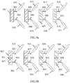
- FIG. 8a shows a case in which two antenna ports for transmitting a reference signal are mapped to four antenna elements.
- a port 0 (802) and a port 4 (803) are mapped to four antenna elements in the first column (801) in a first antenna array; a port 1 (805) and a port 5 (806) are mapped to four antenna elements in the second column (804) in the first antenna array; a port 2 (808) and a port 6 (809) are mapped to four antenna elements in the third column (807) in the first antenna array; and a port 3 (811) and a port 7 (812) are mapped to four antenna elements in the fourth column (810) in the first antenna array.
- the port 0 to the port 7 are antenna ports for transmitting a reference signal.
- the four antenna elements in the first column in the first antenna array are used as an example.
- Beams formed by using the four antenna elements in the first column in the first antenna array are formed by mapping the port 0 and the port 4 to the four antenna elements and by means of transmission. This specific mapping manner may be in a form of weighting. Weighted values that may be used for the port 0 are w0, w1, w2, and w3, and weighted values used for the port 4 that is mapped to the same four antenna elements (or TxRUs) are w4, w5, w6, and w7, where w0, w1, w2, w3, w4, w5, w6, and w7 are complex numbers.
- a direction of a beam, formed by performing weighting by using w0, w1, w2, and w3, of the port 0 is a first direction (813)
- a direction of a beam, formed by performing weighting by using w4, w5, w6, and w7, of the port 4 is a second direction (814).
- Specific beam orientations of the first direction and the second direction may be determined according to a scenario. For example, the first direction may point upwards relative to a horizontal plane, and the second direction may point downwards relative to the horizontal plane; or the first direction and the second direction may point to determined directions separately.
- FIG. 8b is a schematic diagram of mapping antenna ports for transmitting a reference signal to two antenna elements.
- a port 4 (824) is mapped to two antenna elements 841 and 842 in the first column in a first antenna array.
- a Port 0 (823) is mapped to the other two antenna elements in the first column in the first antenna array.
- a mapping relationship of another column is similar.
- the antenna elements 841 and 842 corresponding to the port 0 are weighted, and so on.
- the weighting described above may be precoding weighting, that is, when precoding is being performed on a signal by using a precoding matrix, weighting is performed by using the precoding matrix, which is equivalent to weighting performed on the signal.
- the weighting may be performed on a driver network of a radio frequency by using a circuit.
- the weighting may be driver network weighting; if the slashes indicate TxRU radio units, the weighting manner may be precoding weighting.
- the precoding weighting may be baseband weighting.
- EP 2 690 797 relates to signal transmitting method and device in a multi-node system.
- WO 2014/082266 relates to uplink MU-MIMO method and system.
- WO 2013/029482 relates to method and device for transmitting downlink control information.
- WO 2013/105811 relates to channel estimation method and apparatus using reference signal.
- aspects of the present disclosure provide a technical solution to implement high-efficient data transmission in 3D-MIMO.
- the invention is defined by the independent claims. Preferred embodiments of the invention are stipulated in the dependent claims. While several embodiments and/or examples have been disclosed in this description, the subject matter for which protection is sought is strictly and solely limited to those embodiments and/or examples encompassed by the scope of the appended claims. Embodiments and/or examples mentioned in the description that do not fall under the scope of the claims are useful for understanding the invention.
- the technical solutions in the present disclosure may be applied to various wireless communications systems, for example, a Global System for Mobile Communications (Global System for Mobile communications, GSM for short), a general packet radio service (General Packet Radio Service, GPRS for short) system, a Code Division Multiple Access (Code Division Multiple Access, CDMA for short) system, a CDMA2000 system, a Wideband Code Division Multiple Access (Wideband Code Division Multiple Access, WCDMA for short) system, a Long Term Evolution (Long Term Evolution, LTE for short) system, or a Worldwide Interoperability for Microwave Access (Worldwide Interoperability for Microwave Access, WiMAX for short) system.
- GSM Global System for Mobile communications
- GPRS General Packet Radio Service
- CDMA Code Division Multiple Access
- CDMA2000 Code Division Multiple Access
- Wideband Code Division Multiple Access Wideband Code Division Multiple Access
- WCDMA Worldwide Interoperability for Microwave Access
- WiMAX Worldwide Interoperability for Microwave Access
- a network device in the present disclosure may be a base station.
- the base station may be a base station controller (Base Station Controller, BSC for short) in the GSM system, the GPRS system, or the CDMA system, or may be an evolved NodeB (Evolved NodeB, eNB for short) in the LTE system, or may be a network element such as an access service network base station (Access Service Network Base Station, ASN BS for short) in a WiMAX network.
- UE may be a device such as a mobile phone or a tablet computer.
- the eNB and the UE are used as an example for description in some aspects of the present disclosure. However, types of the base station and a terminal apparatus are not limited.
- a codeword-to-port mapping relationship can be configured flexibly, thereby achieving purposes of improving channel quality and increasing a signal-to-noise ratio.
- apparatus aspects for implementing steps and methods in the foregoing method aspects are further provided. It should be understood that the steps in the method and system aspects of the present disclosure are merely an implementation solution, and the present disclosure sets no limitation to but requires protection of logical integration, splitting, and sequence adjustment to the steps of various solutions; the apparatuses, modules, units, and entities in the apparatus aspects of the present disclosure are merely an implementation solution, and the present disclosure sets no limitation to but requires protection of splitting, combination, or another logical modification to various apparatuses, modules, units, and entities.
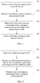
- FIG. 1 shows an aspect of a data transmission method in the present disclosure.
- the method is a method in which user equipment UE transmits data.
- the method may be applied to a network including the user equipment.
- the UE selects at least one mapping relationship set from at least one mapping relationship set, then selects a specific mapping relationship from the selected mapping relationship set, and transmits data according to the mapping relationship. Details are as follows:
- the mapping relationship set may include respective mapping relationships in multiple sets of the first relationship set, the second relationship set, and the third relationship set.
- the mapping relationship set may include a mapping relationship of mapping a codeword to a layer of the codeword in the first relationship set, and further includes a mapping relationship between a layer and a corresponding CSI-RS port in the third relationship set.
- the UE determines a mapping relationship between a codeword and a layer of the codeword from the first relationship set, and the UE further determines a mapping relationship between a layer and a corresponding CSI-RS port from the third relationship set.
- a determining sequence of the first relationship set, the second relationship set, and the third relationship set is not limited in the present disclosure.
- step 102 and step 103 may be: receiving the first reference signal sent by the network device; measuring the first reference signal to obtain a channel coefficient; calculating an equivalent channel coefficient of a channel according to the channel coefficient and a codebook; calculating a signal-to-noise ratio of each layer according to the equivalent channel coefficient of the channel; calculating a channel capacity of each codeword-to-layer mapping relationship in the first relationship set according to the signal-to-noise ratio of each layer; and determining a codeword-to-layer mapping relationship with a maximum channel capacity.
- the first reference signal is a CSI-RS signal.
- the UE measures the CSI-RS to obtain a transmission matrix of the channel.
- the first reference signal is a reference signal corresponding to configuration information of at least two CSI-RSs.
- the first reference signal corresponding to different CSI-RS configuration information is corresponding to different ports. For example, when a quantity of all configured CSI-RS ports is 8 and a quantity of transmission layers is 5, a first CSI-RS signal is corresponding to a port 0 to a port 3, and a second CSI-RS signal is corresponding to a port 4 to a port 7; and correspondingly, a CSI-RS of first configuration information is corresponding to the port 0 to the port 3, and a CSI-RS of second configuration information is corresponding to the port 4 to the port 7.
- a CSI-RS port index of the second configuration information may be numbered still from a port 0.
- the CSI-RS port index of the second configuration information is numbered from a port 4 herein.
- At least two reference signals included in the first reference signal that are corresponding to different CSI-RS configuration information are reference signals obtained by means of precoding weighting.
- at least two reference signals included in the first reference signal that are corresponding to different CSI-RS configuration information are reference signals obtained by means of different precoding weighting.
- the CSI-RS configuration information includes a location of a time-frequency resource occupied by a CSI-RS. As shown in Table 1, different frame structures may be configured according to different CSI-RSs.
- the CSI-RS configuration information includes a CSI-RS subframe configuration, for example, a CSI-RS sending period and a time offset (offset) in Table 2.
- Table 2 CSI-RS subframe configuration CSI-RS subframe configuration I CSI-RS CSI-RS period T CSI-RS (unit: subframe) CSI-RS subframe offset ⁇ CSI-RS (unit: subframe) 0 - 4 5 I CSI-RS 5 - 14 10 I CSI-RS - 5 15 - 34 20 I CSI-RS - 15 35 - 74 40 I CSI-RS - 35 75 - 154 80 I CSI-RS - 75
- CSI-RS port sets of different configuration information have different precoding weighted values. That is, a quantity of CSI-RS ports of the first configuration information is 4: the port 0 to the port 3; a quantity of CSI-RS ports of the second configuration information is 4: port4 ⁇ port7; and the port 0 to the port 3 and the port 4 to the port 7 have different precoding weighting.
- quantities of CSI-RS ports of different configuration information may be different.
- the UE measures a CSI-RS to obtain a channel matrix.
- the UE determines a quantity of layers and determines mapping relationships between the layers and different corresponding CSI-RS ports.
- ⁇ eff (x) indicates an equivalent channel coefficient of the x th layer.
- a signal-to-noise ratio of a corresponding layer is calculated by using an equivalent channel coefficient ⁇ eff (x) of the layer.
- an MMSE algorithm may be used for the calculation.
- the channel capacity of each codeword-to-layer mapping relationship in the first relationship set is calculated according to the signal-to-noise ratio of each layer.
- a capacity formula may be used for the calculation.
- a mapping relationship in the first relationship set is:
- a corresponding codeword 0 is mapped to the third and fourth layers, and a signal-to-noise ratio of the corresponding codeword 0 is SNR_CW(0).
- a corresponding codeword 1 is mapped to the 0 th , first, and second layers, and a signal-to-noise ratio of the corresponding codeword 1 is SNR_CW(1).
- each codeword-to-layer mapping relationship in the first relationship set is calculated in a traversal manner, and the codeword-to-layer mapping relationship corresponding to the maximum capacity is selected.
- mapping relationship is determined by measuring a throughput and by measuring a channel capacity and another parameter, or determined comprehensively by using multiple parameters.
- the present disclosure sets no limitation to but requires protection of all methods that meet selection of a mapping relationship from the first relationship set.
- the first relationship set includes at least a first mapping relationship and a second mapping relationship; in the first mapping relationship, a first codeword is mapped to a first transmission layer set, and a second codeword is mapped to a second transmission layer set; in the second mapping relationship, the first codeword is mapped to a third transmission layer set, and the second codeword is mapped to a fourth transmission layer set.
- Each transmission layer set includes at least one transmission layer, the first transmission layer set is different from the third transmission layer set, and the second transmission layer set is different from the fourth transmission layer set. It should be understood that differences between the sets may mean that an element included in the first transmission layer set is different from an element included in the third transmission layer set, and an element included in the second transmission layer set is different from an element included in the fourth transmission layer set. If there is no explanation, differences between sets involved in the present disclosure may be understood as the foregoing concept, and are not described again.
- At least one first relationship in at least one mapping relationship in the first relationship set meets a first condition, where the first condition is: in mapping relationships between k codewords and respective layers, if the i th codeword and the j th codeword meet i > j, m ⁇ n is met, where a layer with a minimum sequence number in the layer corresponding to the i th codeword is the m th layer, and a layer with a maximum sequence number in the layer corresponding to the j th codeword is the n th layer.
- the following first relationship mapping exists:
- the layer with the minimum sequence number in the layer corresponding to the i th codeword is the m th layer, that is, a minimum sequence number value m of a layer corresponding to the codeword 1 is 1;
- the layer with the maximum sequence number in the layer corresponding to the j th codeword is the n th layer, that is, a maximum sequence number value n of a layer corresponding to the codeword 0 is 4, where m ⁇ n is met.
- the first relationship set when the quantity of transmission layers is greater than or equal to 2, includes at least two first relationships.
- the two first relationships are first relationships of mapping different quantities of codewords to a same quantity of transmission layers.
- the first relationship set may include a case in which one codeword is mapped to five layers and a case in which two codewords are mapped to five layers.
- the base station may notify, by using dynamic signaling or higher layer signaling, the UE of a first relationship in the first relationship set, or a second relationship in the second relationship set, or a third relationship in the third relationship set that is used during scheduling this time to demodulate data.
- Step 104 Send a notification message to the network device, where the notification message is used to indicate the mapping relationship.
- mapping relationships may exist in cases in which rank indications are 2 to 8 and that are included in the first relationship set.
- the mapping relationship message sent by the UE to the network device may indicate one of at least two mapping relationships in the multiple mapping relationships between the codeword and the transmission layers when the quantity of transmission layers is determined.
- a manner of the indication may be sending an index, or the indication is performed in another manner, which is not limited in the present disclosure.
- the first relationship set, the second relationship set, and the third relationship set may be stored in, for example, the UE, or may be obtained from another device.
- a value of a CQI is determined according to the determined mapping relationship, and the channel quality indicator CQI is fed back to the network device. At least one of a quantity or the value of the CQI is obtained according to the determined at least one mapping relationship. It should be understood that manners for calculating the CQI are different because mapping relationships are different. Specifically, after a signal-to-noise ratio of a corresponding layer is calculated by using an equivalent channel coefficient ⁇ eff ( x ) of the layer, an SNR of a codeword is determined according to the signal-to-noise ratio of the corresponding layer (transmission layer). Further, a value of a CQI is obtained according to quantization of the SNR of the codeword.
- the third relationship is a mapping relationship between the DM-RS port and the CSI-RS port.
- mapping relationships included in the first relationship set, the second relationship set, and the third relationship set involved in the aspects of the present disclosure may include only one mapping relationship in some cases.
- a DM-RS port in the second relationship set and a CSI-RS port in the third relationship set may be other pilot ports.
- a codeword to CSI-RS mapping relationship is fixed.
- the UE obtains a difference between codeword to CSI-RS mapping relationships by using a channel quality measurement model, may calculate an optimized mapping relationship by means of measurement, and determines at least one mapping relationship from these mapping relationships, to adjust a codeword to CSI-RS mapping relationship of a channel, thereby improving system flexibility and increasing channel resource utilization.
- the UE determines the quantity of layers.
- the UE determines the quantity of layers according to the first channel matrix and the second channel matrix.
- the UE determines mapping relationships between the layers and a CSI-RS configuration.
- the determining process may be traversing mapping relationships between all the layers and different CSI-RSs.
- the determining process may be finding a mapping relationship that is between a layer and a CSI-RS configuration and that enables a throughput to be optimal or an SNR to be maximum.
- the quantity of layers that is determined by the UE is 5, and the five layers are a layer 0, a layer 1, a layer 2, a layer 3, and a layer 4.
- Respective mapping relationships between each layer and different CSI-RS configurations exist.
- the UE traverses the mapping relationships between all the layers and the different CSI-RSs to find a mapping relationship that is between each layer and a CSI-RS configuration and that enables a throughput to be optimal or an SNR to be maximum.
- the layer 0 and the layer 1 are mapped to a first CSI-RS configuration
- the layer 2, the layer 3, and the layer 4 are mapped to a second CSI-RS configuration.
- the UE feeds back the optimal mapping relationship between the layer and the different CSI-RS configurations to the base station in step 104.
- the mapping relationship may be a correspondence. For example, if the UE determines that the layer 0 in the first CSI-RS configuration is superior to that in the second CSI-RS configuration, the UE determines that the layer 0 is mapped to the first CSI-RS configuration. Cases for the layer 1 to the layer 4 are similar. Alternatively, a limited quantity of different configuration combinations of all layers may be traversed to determine an optimal case, and determine an optimal configuration corresponding to each layer.
- a layer 0 (i 1 ), a layer 1 (i 2 ), a layer 2 (i 3 ), a layer 3 (i 4 ), and a layer 4 (i 5 ) are configurations of five layers.
- i 1 1
- a first configuration is selected for the 0 th layer.
- i 1 2
- a second configuration is selected for the 0 th layer.
- Cases for i 2 to i 5 are similar. In this way, there are 2 5 configuration combinations in total.
- a system may traverse the 2 5 configurations and determine an optimal configuration manner.
- the configuration manner may be a CSI-RS configuration corresponding to each layer.
- a traversal range may be a subset of the foregoing 2 5 configurations. It should be understood that the configuration manner and value selection are merely an example.
- the correspondence between the layer and the CSI-RS configuration is the third mapping relationship.
- the UE After the UE determines the third mapping relationship, the UE further feeds back PMI (precoding matrix indication) precoding matrix indication information when a CSI-RS configuration is selected.
- PMI precoding matrix indication
- the layer 0 and the layer 1 are mapped to the first CSI-RS configuration; if four antenna ports exist, a precoding matrix W1 is determined according to configurations of the layer 0 and the layer 1.
- W1 is a 4 ⁇ 2 matrix.
- a quantity of rows is corresponding to the quantity of antenna ports, and a quantity of columns is a quantity of layers of the first CSI-RS configuration.
- the layer 2, the layer 3, and the layer 4 are mapped to the second CSI-RS configuration.
- a precoding matrix W2 is determined according to configurations of the layer 2, the layer 3, and the layer 4.
- W2 is a 4 ⁇ 3 matrix, that is, W2 has four rows and three columns.
- the third relationship may be a correspondence that is between the transmission layers and a CSI process and that is fed back by the UE, or correspondences that are between the transmission layers and different CSI-RS ports and that are fed back by the UE.
- a CSI process is defined as configuring, by the base station, a non-zero power CSI-RS and an interference measurement reference signal IMRS (interference measurement resource signal).
- the UE feeds back CSI (channel state information) by using the non-zero power CSI-RS and the IMRS.
- the base station may configure multiple CSI processes for the UE. Each CSI process has an index of the CSI process.
- the UE feeds back an optimal correspondence between the transmission layers and different CSI processes by using the CSI processes.
- a CSI-RS configuration includes multiple CSI-RS ports.
- the third relationship may be correspondences that are between different transmission layers and different CSI-RS ports and that are fed back by the UE by measuring a channel.
- the UE may further receive indication information sent by the network device.
- the UE feeds back a corresponding precoding matrix indication PMI and the CQI or feeds back only the third relationship and the CQI according to the feedback information.
- the CSI-RS configuration information fed back in the foregoing feedback process may be one or more indications used to instruct the eNB to determine corresponding configuration information according to the indication.
- the port to CSI-RS mapping relationship may also be selection information. For example, when the quantity of layers is 5, when the layer 0 is corresponding to the first CSI-RS configuration, 0 is fed back; when the layer 0 is corresponding to the second SCI-RS configuration, 1 is fed back. Cases for the layer 1 to the layer 5 are similar.
- the port to CSI-RS mapping relationship may be an all-layer joint indication. That is, a selection matrix or a selection indication is fed back to indicate CSI-RS configuration information corresponding to all the layers.
- FIG. 2 shows an aspect of a data transmission method in the present disclosure.
- the method is a method in which a network side device transmits data.
- the method may be applied to a network including a first network side device and specifically includes the following steps:
- the at least one mapping relationship is determined by the UE from the mapping relationship set according to the first reference signal.
- the mapping relationship set includes at least one of a first relationship set, a second relationship set, or a third relationship set.
- the first relationship set includes multiple mapping relationships between a codeword and transmission layers when a quantity of transmission layers is determined.
- the second relationship set includes multiple mapping relationships between the transmission layers and a demodulation reference signal DM-RS port.
- the third relationship set includes multiple mapping relationships between the transmission layers and a channel state information-reference signal CSI-RS port.
- the mapping relationship set may include multiple mapping relationships in the first relationship set, the second relationship set, and the third relationship set.
- the one mapping relationship may include a mapping relationship in the first relationship set, that is, a mapping relationship of mapping a codeword to a transmission layer of the codeword when the quantity of transmission layers is determined, and further includes a mapping relationship in the third relationship set, that is, a mapping relationship between a transmission layer and a corresponding CSI-RS port.
- the UE determines a mapping relationship between a codeword and a layer of the codeword from the first relationship set, and the UE further determines a mapping relationship between a layer and a corresponding CSI-RS port from the third relationship set.
- a determining sequence of the first relationship set, the second relationship set, and the third relationship set is not limited in the present disclosure.
- the third relationship is a mapping relationship between the DM-RS port and the CSI-RS port.
- the first reference signal is a CSI-RS signal. Further, the first reference signal includes at least two reference signals corresponding to different CSI-RS configuration information, and the reference signals corresponding to the different CSI-RS configuration information are corresponding to different ports.
- a channel quality indicator CQI sent by the UE is received, and at least one of a quantity of the CQIs or a value of the CQI is obtained according to the determined at least one mapping relationship.
- the first relationship set includes at least a first mapping relationship and a second mapping relationship; in the first mapping relationship, a first codeword is mapped to a first transmission layer set, and a second codeword is mapped to a second transmission layer set; in the second mapping relationship, the first codeword is mapped to a third transmission layer set, and the second codeword is mapped to a fourth transmission layer set.
- Each transmission layer set includes at least one transmission layer, the first transmission layer is different from the third transmission layer set, and the second transmission layer set is different from the fourth transmission layer set.
- At least one first relationship in at least one mapping relationship in the first relationship set meets a first condition, where the first condition is: in mapping relationships between k codewords and respective layers, if the i th codeword and the j th codeword meet i > j, m ⁇ n is met, where each codeword is mapped to at least one layer, a layer with a minimum sequence number in the layer corresponding to the i th codeword is the m th layer, and a layer with a maximum sequence number in the layer corresponding to the j th codeword is the n th layer.
- the first condition is: in mapping relationships between k codewords and respective layers, if the i th codeword and the j th codeword meet i > j, m ⁇ n is met, where each codeword is mapped to at least one layer, a layer with a minimum sequence number in the layer corresponding to the i th codeword is the m th layer, and a layer with a maximum sequence number
- the present disclosure provides a case of the first relationship set that may exist in cases in which rank indications are 2 to 8.
- the mapping relationship message received by the network device may indicate one of at least two mapping relationships in the multiple mapping relationships between the codeword and the transmission layers when the quantity of transmission layers is determined.
- a manner of the indication may be sending an index, or the indication is performed in another manner, which is not limited in the present disclosure.
- the first relationship set, the second relationship set, and the third relationship set may be stored in, for example, the network device, or may be obtained from another device.
- Step 203 The network device obtains the at least one mapping relationship from the mapping relationship set according to the mapping relationship message.
- a network device sends the first reference signal to UE, so that the UE obtains a difference between codeword to CSI-RS mapping relationships by using a channel quality measurement model and may calculate an optimized mapping relationship by means of measurement.
- the network device receives a mapping relationship message sent by the UE, determines a codeword to CSI-RS mapping relationship according to an indication of the mapping relationship message, and transmits data according to the mapping relationship, thereby increasing channel resource utilization by means of flexible configuration.
- step 202 of receiving, by the network device, a notification message that is sent by the UE and that is generated according to the first reference signal, where the notification message is used to indicate at least one mapping relationship in a mapping relationship set may include the following:
- the third relationship may be various corresponding third relationships in the aspect shown in FIG. 1 .
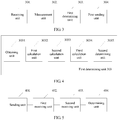
- FIG. 3 shows an apparatus aspect of user equipment UE in the present disclosure.
- the UE apparatus is configured to transmit data, and the apparatus may be applied to a network including the UE.
- the UE selects at least one mapping relationship set from at least one mapping relationship set, then selects a specific mapping relationship from the selected mapping relationship set, and transmits data according to the mapping relationship.
- the UE specifically includes a receiving unit 301, a measurement unit 302, a first determining unit 303, and a first sending unit 304.
- the receiving unit 301 is configured to receive a first reference signal sent by a network device.
- the measurement unit 302 is configured to measure the first reference signal to obtain a measurement result.
- the first determining unit 303 is configured to determine at least one mapping relationship from a mapping relationship set according to the measurement result, where the mapping relationship set includes at least one of a first relationship set, a second relationship set, or a third relationship set, the first relationship set includes multiple mapping relationships between a codeword and transmission layers when a quantity of transmission layers is determined, the second relationship set includes multiple mapping relationships between the transmission layers and a demodulation reference signal DM-RS port, and the third relationship set includes multiple mapping relationships between the transmission layers and a channel state information-reference signal CSI-RS port.
- the mapping relationship set may include multiple mapping relationships in the first relationship set, the second relationship set, and the third relationship set.
- the mapping relationship set may include a mapping relationship of mapping a codeword to a transmission layer of the codeword in the first relationship set when the quantity of transmission layers is determined, and further includes multiple mapping relationships between the transmission layers and a channel state information-reference signal CSI-RS port in the third relationship set.
- the UE determines a mapping relationship of mapping a codeword to a transmission layer of the codeword from the first relationship set when the quantity of transmission layers is determined, and the UE determines multiple mapping relationships between the transmission layers and a channel state information-reference signal CSI-RS port from the third relationship set.
- a determining sequence of the first relationship set, the second relationship set, and the third relationship set is not limited in the present disclosure.
- FIG. 4 shows an aspect of the first determining unit 303 in the present disclosure, and the first determining unit may include:
- the first reference signal may be a CSI-RS signal.
- the measurement unit 302 measures the CSI-RS to obtain a transmission matrix of the channel.
- the first reference signal includes at least two reference signals corresponding to different CSI-RS configuration information, and the reference signals corresponding to the different CSI-RS configuration information are corresponding to different ports. For example, when a quantity of ports is 8 and a quantity of layers is 5, a first CSI-RS signal is corresponding to a port 0 to a port 3, and a second CSI-RS signal is corresponding to a port 4 to a port 7.
- the obtaining unit 3031 obtains the channel coefficient according to the measurement result.
- the channel coefficient may be indicated in a form of a matrix.
- the obtaining unit obtains two channel matrices.
- the third calculation unit 3034 is configured to calculate the channel capacity of each codeword-to-layer mapping relationship in the first relationship set according to the signal-to-noise ratio of each layer.
- calculating the channel capacity of each codeword-to-transmission-layer mapping relationship in the first relationship set may be implemented by using multiple methods.
- a signal-to-noise ratio of a corresponding layer is calculated by using an equivalent channel coefficient ⁇ eff ( x ) of the layer.
- a minimum mean square error MMSE (Minimum Mean Square Error) algorithm may be used for the calculation.
- the channel capacity of each codeword-to-transmission-layer mapping relationship in the first relationship set is calculated according to the signal-to-noise ratio of each layer.
- a capacity formula may be used for the calculation.
- a mapping relationship in the first relationship set is:
- a corresponding codeword 0 is mapped to the third and fourth layers, and a signal-to-noise ratio of the corresponding codeword 0 is SNR_CW(0).
- a corresponding codeword 1 is mapped to the 0 th , first, and second layers, and a signal-to-noise ratio of the corresponding codeword 1 is SNR_CW(0).
- Each codeword-to-layer mapping relationship in the first relationship set is calculated according to the method.
- the second determining unit 3035 is configured to determine the codeword-to-layer mapping relationship with the maximum channel capacity. Optionally, the codeword-to-layer mapping relationship corresponding to the maximum capacity is selected.
- each codeword-to-transmission-layer mapping relationship described above is merely an example.
- the mapping relationship is determined by measuring a throughput and by measuring a channel capacity and another parameter, or determined comprehensively by using multiple parameters.
- the present disclosure sets no limitation to but requires protection of all methods that meet selection of a mapping relationship from the first relationship set.
- there may be logical combination, splitting, and modification to the apparatuses and units in this aspect.
- the first determining unit 303 may be a processor, and subunits included in the first determining unit 303 may be different or same adders and multipliers or other operation modules or processing modules of the processor.
- At least one first relationship in at least one mapping relationship in the first relationship set meets a first condition, where the first condition is: in mapping relationships between k codewords and respective layers, if the i th codeword and the j th codeword meet i > j, m ⁇ n is met, where each codeword is mapped to at least one layer, a layer with a minimum sequence number in the layer corresponding to the i th codeword is the m th layer, and a layer with a maximum sequence number in the layer corresponding to the j th codeword is the n th layer.
- the layer with the minimum sequence number in the layer corresponding to the i th codeword is the m th layer, that is, a minimum sequence number value m of a layer corresponding to the codeword 1 is 1;
- the layer with the maximum sequence number in the layer corresponding to the j th codeword is the n th layer, that is, a maximum sequence number value n of a layer corresponding to the codeword 0 is 4, where m ⁇ n is met.
- first relationship set there are some possible first relationship sets provided in the first relationship set aspect shown in FIG. 1 , and details are not described herein again.
- the first sending unit 304 is configured to send a notification message to the network device, where the notification message is used to indicate the mapping relationship determined by the first determining unit.
- a channel quality indicator CQI is fed back to the network device, and at least one of a quantity of the CQIs or a value of the CQI is obtained according to the determined at least one mapping relationship.
- the third relationship is a mapping relationship between the DM-RS port and the CSI-RS port.
- the present disclosure sets no limitation to integration, splitting, and logical modification to the modules or the units in the aspects.
- the first calculation unit, the second calculation unit, and the third calculation unit may be combined into one calculation unit.
- the UE When UE measures a first reference signal and determines channel quality, a codeword to CSI-RS mapping relationship is fixed.
- the UE obtains a difference between layer to CSI-RS mapping relationships by using a channel quality measurement model, may calculate an optimized mapping relationship by means of measurement, and determines at least one mapping relationship from these mapping relationships, to adjust a codeword to CSI-RS mapping relationship of a channel, thereby improving system flexibility and increasing channel resource utilization.
- the UE apparatus shown in FIG. 4 can also implement the aspect shown in FIG. 1 .
- FIG. 5 shows an apparatus aspect of a network device for implementing the present disclosure in the present disclosure.
- the apparatus is a network device, and the apparatus may be applied to a network including the network device.
- the apparatus is configured to send a first reference signal and receive a message indicating a mapping relationship.
- the apparatus specifically includes a sending unit 401, a first receiving unit 402, and a determining unit 404.
- the sending unit 401 is configured to send a reference signal to user equipment UE.
- the network device is an evolved NodeB eNB.
- the first receiving unit 402 is configured to receive a mapping relationship message that is sent by the UE and that is generated according to the first reference signal, where the notification message is used to indicate at least one mapping relationship in a mapping relationship set.
- the at least one mapping relationship is determined by the UE from the mapping relationship set according to the first reference signal.
- the mapping relationship set includes at least one of a first relationship set, a second relationship set, or a third relationship set.
- the first relationship set includes multiple mapping relationships between a codeword and transmission layers when a quantity of transmission layers is determined.
- the second relationship set includes multiple mapping relationships between the transmission layers and a demodulation reference signal DM-RS port.
- the third relationship set includes multiple mapping relationships between the transmission layers and a channel state information-reference signal CSI-RS port.
- the mapping relationship set may include multiple mapping relationships in the first relationship set, the second relationship set, and the third relationship set.
- the one mapping relationship may include a mapping relationship in the first relationship set, and further includes a mapping relationship in the third relationship set.
- the UE determines multiple mapping relationships between a codeword and the transmission layers from the first relationship set when the quantity of transmission layers is determined, and the UE further determines multiple mapping relationships between the transmission layers and a channel state information-reference signal CSI-RS port from the third relationship set.
- a determining sequence of the first relationship set, the second relationship set, and the third relationship set is not limited in the present disclosure.
- the third relationship further includes a mapping relationship between the corresponding DM-RS port and the corresponding CSI-RS port.
- the first reference signal is a CSI-RS signal. Further, the first reference signal includes at least two reference signals corresponding to different CSI-RS configuration information, and the reference signals corresponding to the different CSI-RS configuration information are corresponding to different ports.
- the apparatus further includes: a second receiving unit 403, configured to receive a channel quality indicator CQI sent by the UE. At least one of a quantity of the CQIs or a value of the CQI is obtained according to the determined at least one mapping relationship.
- the first relationship set includes at least a first mapping relationship and a second mapping relationship; in the first mapping relationship, a first codeword is mapped to a first transmission layer set, and a second codeword is mapped to a second transmission layer set; in the second mapping relationship, the first codeword is mapped to a third transmission layer set, and the second codeword is mapped to a fourth transmission layer set.
- Each transmission layer set includes at least one transmission layer, the first transmission layer is different from the third transmission layer set, and the second transmission layer set is different from the fourth transmission layer set.
- At least one first relationship in at least one mapping relationship in the first relationship set meets a first condition, where the first condition is: in mapping relationships between k codewords and respective layers, if the i th codeword and the j th codeword meet i > j, m ⁇ n is met, where each codeword is mapped to at least one layer, a layer with a minimum sequence number in the layer corresponding to the i th codeword is the m th layer, and a layer with a maximum sequence number in the layer corresponding to the j th codeword is the n th layer.
- step 103 in the aspect shown in FIG. 1 , and details are not described herein again.
- first relationship set there are some possible first relationship sets provided in the first relationship set aspect shown in FIG. 1 , and details are not described herein again.
- the mapping relationship message received by the network device may indicate one of at least two first mapping relationships.
- a manner of the indication may be sending an index, or the indication is performed in another manner, which is not limited in the present disclosure.
- the first relationship set, the second relationship set, and the third relationship set may be stored in, for example, the network device, or may be obtained from another device.
- the determining unit 404 is configured to obtain the at least one mapping relationship from the mapping relationship set according to the mapping relationship message.
- first receiving unit 402 and the second receiving unit 403 may be combined into one receiving unit.
- a sending unit in a network device sends a first reference signal to UE, so that the UE obtains a difference between codeword to CSI-RS mapping relationships by using a channel quality measurement model and may calculate an optimized mapping relationship by means of measurement.
- a receiving unit receives a mapping relationship message sent by the UE, determines a codeword to CSI-RS mapping relationship according to an indication of the mapping relationship message, and transmits data according to the mapping relationship, thereby increasing channel resource utilization by means of flexible configuration.
- FIG. 6 shows an aspect of another computer system in the present disclosure.
- the computer system may be specifically a processor-based computer, for example, a general purpose personal computer (PC) or a portable device such as a tablet computer or a smartphone.
- PC general purpose personal computer
- portable device such as a tablet computer or a smartphone.
- the foregoing computer system may include a bus, a processor 501, an input device 502, an output device 503, a communications interface 504, and a memory 505.
- the processor 501, the input device 502, the output device 503, the communications interface 504, and the memory 505 are connected to each other by using the bus.
- the bus may include a path for information transfer between components in the computer system.
- the processor 501 may be a general purpose processor, for example, a general purpose central processing unit (CPU), a network processor (Network Processor, NP for short), or a microprocessor, or may be an application-specific integrated circuit (application-specific integrated circuit, ASIC), or one or more integrated circuits configured to control execution of a program in the solutions in the present disclosure, or may be a digital signal processor (DSP), an application-specific integrated circuit (ASIC), a field programmable gate array (FPGA) or another programmable logic device, a discrete gate or transistor logic device, or a discrete hardware component.
- DSP digital signal processor
- ASIC application-specific integrated circuit
- FPGA field programmable gate array
- the memory 505 stores a program for executing the technical solutions in the present disclosure and may further store an operating system and another application program.
- the program may include program code, and the program code includes a computer operation instruction.
- the memory 505 may be a read-only memory (read-only memory, ROM), another type of static storage device that can store static information and a static instruction, a random access memory (random access memory, RAM), another type of dynamic storage device that can store information and an instruction, a magnetic disk storage, or the like.
- the input device 502 may include an apparatus, for example, a keyboard, a mouse, a camera, a scanner, a light pen, a voice input apparatus, or a touchscreen, that receives data and information that are input by a user.
- an apparatus for example, a keyboard, a mouse, a camera, a scanner, a light pen, a voice input apparatus, or a touchscreen, that receives data and information that are input by a user.
- the output device 503 may include an apparatus, for example, a display screen, a printer, or a speaker, that allows information to be output to a user.
- the communications interface 504 may include an apparatus using any transceiver or the like, to communicate with another device or a communications network, for example, the Ethernet, a radio access network (RAN), or a wireless local area network (WLAN).
- RAN radio access network
- WLAN wireless local area network
- the processor 501 executes the program stored in the memory 505 and is configured to implement a signal transmission method provided in any aspect of the present disclosure and implement any apparatus in this aspect.
- the mapping relationship and the one mapping relationship may be a single mapping relationship between ports, for example, a codeword-to-layer mapping relationship, multiple mapping relationships between layers and a DM-RS port, or a mapping relationship between a DM-RS port and a CSI-RS, or may be one mapping relationship that includes multiple mapping relationships from a perspective of a system.
- the one mapping relationship may include a codeword-to-layer mapping relationship, multiple mapping relationships between layers and a DM-RS port, and a mapping relationship between the DM-RS port and a CSI-RS port, or may be an independent codeword to CSI-RS mapping relationship.
- the following specifically describes an implementation method in the present disclosure by using an aspect. Specifically, this aspect may be used as a method for determining the second relationship.
- this aspect may be used as a method for determining the second relationship.
- the present disclosure provides method implementation manners from perspectives of UE and an eNB.
- the UE sends an SRS reference signal, where the SRS reference signal is used by the eNB to measure a channel.
- the UE receives a signal W ⁇ x obtained by performing precoding processing.
- the UE obtains a DM-RS reference signal x.
- the UE obtains, according to x and W ⁇ x, an equivalent channel H Rx ⁇ Tx W of ports corresponding to n antennas corresponding to the DM-RS reference signal x.
- the UE determines, according to H Rx ⁇ Tx W , a mapping relationship between the m layers and n corresponding DM-RS demodulation pilot ports.
- the foregoing method may be implemented inside the UE apparatus, and the sending an SRS reference signal may be implemented by a sending unit.
- the receiving, by the UE, a signal W ⁇ x obtained by performing precoding processing may be implemented by a receiving unit.
- the obtaining, by the UE according to x and W ⁇ x, an equivalent channel H Rx ⁇ Tx W of ports corresponding to n antennas corresponding to the DM-RS reference signal x may be implemented by an obtaining unit.
- the determining, by the UE according to H Rx ⁇ Tx W , a mapping relationship between the m layers and n corresponding DM-RS demodulation pilot ports may be implemented by a determining unit.
- the obtaining, by the UE, a DM-RS reference signal x may be implemented by a memory or an obtaining unit according to a structure of the UE or a predetermined method.
- the eNB receives the SRS signal.
- the eNB measures the SRS reference signal and obtains, according to the measurement result, the signal W ⁇ x obtained by performing precoding processing on the DM-RS reference signal.
- the eNB sends W ⁇ x to the UE.
- the foregoing method may be implemented inside the eNB apparatus, and the receiving, by the eNB, the SRS signal may be implemented by a receiving unit.
- the measuring, by the eNB, the SRS reference signal may be implemented by a measurement unit.
- the obtaining, according to the measurement result, the signal W ⁇ x obtained by performing precoding processing on the DM-RS reference signal may be implemented by an obtaining unit.
- the sending, by the eNB, W ⁇ x to the UE may be implemented by a sending unit.
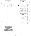
- FIG. 7 shows a system aspect of the present disclosure.
- a network device is an eNB. Details are as follows: Step 601: UE sends an SRS reference signal to the eNB.
- Step 602 The eNB receives the SRS signal.
- Step 603 The eNB measures the SRS reference signal and obtains an uplink channel coefficient H Tx ⁇ Rx according to the measurement result, where Tx is a quantity of antenna ports corresponding to the base station, and Rx is a quantity of antenna ports corresponding to the UE.
- the measurement process and the process of obtaining the uplink channel coefficient according to the measurement result in step 603 may be divided into two or more steps for execution, which is not limited in the present disclosure.
- Step 604 The eNB obtains a channel coefficient H Rx ⁇ Tx of a downlink channel according to channel reciprocity and the uplink channel coefficient H Tx ⁇ Rx .
- Step 605 The eNB obtains a precoding matrix according to the downlink channel coefficient H Rx ⁇ Tx .
- the precoding matrix W [ w 1 w 2 ⁇ w n ] may be obtained in a singular value decomposition manner, where w z is the z th column in W, and a quantity of columns in W is n. It should be understood that the present disclosure sets no limitation to a manner for obtaining W according to H Rx ⁇ Tx .
- Step 606 The eNB performs precoding processing on a DM-RS reference signal x according to W, to obtain a signal W ⁇ x obtained by performing precoding processing on the DM-RS reference signal.
- x may be pre-stored in the eNB and the UE; or optionally, x is stored in either the eNB or the UE and is notified to the peer end; or optionally, the eNB and/or the UE obtain or obtains x by receiving a message sent by another device.
- Step 607 The eNB sends W ⁇ x to the UE, where a port quantity of the DM-RS reference signal x is n.
- the present disclosure sets no limitation to a manner for obtaining H Rx ⁇ Tx W according to y and x, and the manner may be implemented by using a least square channel estimation algorithm or a minimum mean square error channel estimation algorithm.
- Step 609 Determine, according to H Rx ⁇ Tx W , a mapping relationship between the m layers and n corresponding DM-RS demodulation pilot ports.
- H Rx ⁇ Tx W [ H eff_ 1 H eff_ 2 ⁇ H eff_n ]
- H eff_v refers to an equivalent channel corresponding to the v th port corresponding to the v th column in H Rx ⁇ Tx W .
- a signal-to-noise ratio corresponding to H eff_v is obtained.
- the mapping relationship between the m layers and the n corresponding DM-RS demodulation pilot ports is determined according to the signal-to-noise ratio.
- some ports with a high signal-to-noise ratio are selected from all H eff_v , and the layers are mapped to the some selected ports with the high signal-to-noise ratio. It should be understood that a value of m is less than or equal to a value of n.
- the present disclosure may be implemented by hardware, firmware, or a combination thereof.
- the foregoing functions may be stored in a computer-readable medium or transmitted as one or more instructions or code in the computer-readable medium.
- the computer-readable medium includes a computer storage medium and a communications medium, where the communications medium includes any medium that enables a computer program to be transmitted from one place to another place.
- the storage medium may be any available medium accessible to a computer.
- the computer-readable medium may include a RAM, a ROM, an EEPROM, a CD-ROM, or another optical disc storage or disk storage medium, or another magnetic storage device, or any other medium that can carry or store expected program code in a form of an instruction or a data structure and can be accessed by a computer.
- any connection may be appropriately defined as a computer-readable medium.
- the coaxial cable, optical fiber/cable, twisted pair, DSL, or wireless technologies such as infrared ray, radio, and microwave are included in definition of a medium to which they belong.
- a disk (Disk) and disc (disc) used in the present disclosure include a compact disc (CD), a laser disc, an optical disc, a digital versatile disc (DVD), a floppy disk, and a Blu-ray disc, where the disk generally copies data by a magnetic means, and the disc copies data optically by a laser means.
Landscapes
- Engineering & Computer Science (AREA)
- Computer Networks & Wireless Communication (AREA)
- Signal Processing (AREA)
- Quality & Reliability (AREA)
- Physics & Mathematics (AREA)
- Mathematical Physics (AREA)
- Mobile Radio Communication Systems (AREA)
Claims (12)
- Signalübertragungsverfahren, durchgeführt durch eine Benutzerausrüstung, umfassend:Empfangen (101) eines ersten Referenzsignals, gesandt durch eine Netzwerkvorrichtung, wobei das erste Referenzsignal ein vorcodiertes Referenzsignal ist, vorcodiert unter Verwendung einer Vorcodierungsmatrix, bestimmt gemäß Abwärtsstrecken-Kanalkoeffizienten, erhalten aus Aufwärtsstrecken-Kanalmessungen eines Sondierungsreferenzsignals bzw. SRS-Signals, übertragen durch die Benutzerausrüstung;Messen (102) des ersten Referenzsignals, um ein Messergebnis zu erhalten;Bestimmen (103) einer Abbildungsbeziehung aus jeder von mehreren Abbildungsbeziehungsmengen gemäß dem Messergebnis, wobei die mehreren Abbildungsbeziehungsmengen eine erste Beziehungsmenge und mindestens eine einer zweiten Beziehungsmenge und einer dritten Beziehungsmenge umfassen, wobei die erste Beziehungsmenge mehrere Abbildungsbeziehungen zwischen einem Codewort und einer Übertragungsschicht umfasst, wenn eine Quantität von Übertragungsschichten bestimmt ist, die zweite Beziehungsmenge mehrere Abbildungsbeziehungen zwischen den Übertragungsschichten und einem Demodulationsreferenzsignal- bzw. DM-RS-Anschluss umfasst und die dritte Beziehungsmenge mehrere Abbildungsbeziehungen zwischen den Übertragungsschichten und einem Kanalzustandsinformationen-Referenzsignal- bzw. CSI-RS-Anschluss umfasst; undSenden (104) einer Benachrichtigungsnachricht an die Netzwerkvorrichtung, wobei die Benachrichtigungsnachricht verwendet wird, die bestimmten Abbildungsbeziehungen anzugeben;wobei Bestimmen einer Abbildungsbeziehung aus der zweiten Beziehungsmenge umfasst: Erhalten von Signal-zu-Rauschen-Verhältnissen korrespondierend mit einem effektiven Kanal korrespondierend mit jedem DM-RS-Demodulationspilotanschluss, wobei jeder effektive Kanal das Produkt der Abwärtsstrecken-Kanalkoeffizienten und der Vorcodierungsmatrix ist,Auswählen von zwei oder mehreren DM-RS-Demodulationspilotanschlüssen basierend auf Signal-zu-Rauschen-Verhältnissen und Abbilden einzelner Schichten auf ausgewählte DM-RS-Demodulationspilotanschlüsse; undwobei Bestimmen einer Abbildungsbeziehung aus der dritten Beziehungsmenge umfasst: Traversieren von Abbildungsbeziehungen zwischen jeder Übertragungsschicht und aus zwei oder mehreren CSI-RS-Konfigurationen ausgewählten verschiedenen CSI-RS-Konfigurationen und Auswählen einer Abbildungsbeziehung zwischen einer Übertragungsschicht und einer CSI-RS-Konfiguration mit maximalem Signal-zu-Rauschen-Verhältnis, und wobei das erste Referenzsignal CSI-RSs umfasst und mit den zwei oder mehreren CSI-RS-Konfigurationen korrespondiert.
- Verfahren nach Anspruch 1, ferner umfassend: Senden eines Kanalqualitätsindikators CQI an die Netzwerkvorrichtung, wobei mindestens eines einer Quantität der CQIs oder eines Werts des CQI gemäß den bestimmten Abbildungsbeziehungen erhalten wird.
- Verfahren nach Anspruch 1, wobei, wenn die Quantität von Übertragungsschichten größer als oder gleich 2 ist;
die erste Beziehungsmenge mindestens eine erste Abbildungsbeziehung und ein zweite Abbildungsbeziehung umfasst, in der ersten Abbildungsbeziehung ein erstes Codewort auf eine erste Übertragungsschichtmenge abgebildet ist und ein zweites Codewort auf eine zweite Übertragungsschichtmenge abgebildet ist; in der zweiten Abbildungsbeziehung das erste Codewort auf eine dritte Übertragungsschichtmenge abgebildet ist und das zweite Codewort auf eine vierte Übertragungsschichtmenge abgebildet ist; wobei
jede Übertragungsschichtmenge mindestens eine Übertragungsschicht umfasst, die erste Übertragungsschichtmenge von der dritten Übertragungsschichtmenge verschieden ist und die zweite Übertragungsschichtmenge von der vierten Übertragungsschichtmenge verschieden ist. - Verfahren nach Anspruch 1, wobei, wenn die Quantität von Übertragungsschichten größer als oder gleich 2 ist;
mindestens eine erste Beziehung in der bestimmten Abbildungsbeziehung in der ersten Beziehungsmenge eine erste Bedingung erfüllt, wobei die erste Bedingung ist:
in Abbildungsbeziehungen zwischen k Codeworten und jeweiligen Übertragungsschichten, wenn das i-te Codeword und das j-te Codewort i>j erfüllen, wird m<n erfüllt, wobei jedes Codewort auf mindestens eine Übertragungsschicht abgebildet ist, eine Schicht mit einer minimalen Folgenummer in der Schicht korrespondierend mit dem i-ten Codewort die m-te Übertragungsschicht ist und eine Schicht mit einer maximalen Folgenummer in der Schicht korrespondierend mit dem j-ten Codewort die n-te Übertragungsschicht ist. - Verfahren nach Anspruch 1, wobei das erste Referenzsignal ein CSI-RS-Signal ist.
- Verfahren nach Anspruch 5, wobei das erste Referenzsignal mindestens zwei Referenzsignale korrespondierend mit verschiedenen CSI-RS-Konfigurationsinformationen umfasst und die Referenzsignale korrespondierend mit den verschiedenen CSI-RS-Konfigurationsinformationen mit verschiedenen Anschlüssen korrespondieren; die in dem ersten Referenzsignal enthaltenen mindestens zwei Referenzsignale, die mit den verschiedenen CSI-RS-Konfigurationsinformationen korrespondieren, mittels Vorcodierungsgewichtung erhaltene Referenzsignale sind.
- Benutzerausrüstung UE, umfassend:eine Empfangseinheit (301), konfiguriert zum Empfangen eines durch eine Netzwerkvorrichtung gesandten ersten Referenzsignals, wobei das erste Referenzsignal ein vorcodiertes Referenzsignal ist, vorcodiert unter Verwendung einer Vorcodierungsmatrix, bestimmt gemäß Abwärtsstrecken-Kanalkoeffizienten, erhalten aus Aufwärtsstrecken-Kanalmessungen eines Sondierungsreferenzsignals bzw. SRS-Signals, übertragen durch die Benutzerausrüstung;eine Messungseinheit (302), konfiguriert zum Messen des ersten Referenzsignals, um ein Messergebnis zu erhalten;eine erste Bestimmungseinheit (303), konfiguriert zum Bestimmen einer Abbildungsbeziehung aus jeden von mehreren Abbildungsbeziehungsmengen gemäß dem Messergebnis, wobei die mehreren Abbildungsbeziehungsmengen eine erste Beziehungsmenge und mindestens eine einer zweiten Beziehungsmenge und einer dritten Beziehungsmenge umfassen, wobei die erste Beziehungsmenge mehrere Abbildungsbeziehungen zwischen einem Codewort und einer Übertragungsschicht umfasst, wenn eine Quantität von Übertragungsschichten bestimmt ist, die zweite Beziehungsmenge mehrere Abbildungsbeziehungen zwischen den Übertragungsschichten und einem Demodulationsreferenzsignal- bzw. DM-RS-Anschluss umfasst und die dritte Beziehungsmenge mehrere Abbildungsbeziehungen zwischen den Übertragungsschichten und einem Kanalzustandsinformationen-Referenzsignal- bzw. CSI-RS-Anschluss umfasst; undeine erste Sendeeinheit (304), konfiguriert zum Senden einer Benachrichtigungsnachricht an die Netzwerkvorrichtung, wobei die Benachrichtigungsnachricht verwendet wird, die bestimmten Abbildungsbeziehungen, bestimmt durch die erste Bestimmungseinheit, anzugeben;wobei die erste Bestimmungseinheit konfiguriert ist zum Bestimmen einer Abbildungsbeziehung aus der zweiten Beziehungsmenge durch: Erhalten von Signal-zu-Rauschen-Verhältnissen korrespondierend mit einem effektiven Kanal korrespondierend mit jedem DM-RS-Demodulationspilotanschluss, wobei jeder effektive Kanal das Produkt der Abwärtsstrecken-Kanalkoeffizienten und der Vorcodierungsmatrix ist,Auswählen von zwei oder mehreren DM-RS-Demodulationspilotanschlüssen basierend auf Signal-zu-Rauschen-Verhältnissen und Abbilden einzelner Schichten auf ausgewählte DM-RS-Demodulationspilotanschlüsse; undwobei die erste Bestimmungseinheit konfiguriert ist zum Bestimmen einer Abbildungsbeziehung aus der dritten Beziehungsmenge durch Traversieren von Abbildungsbeziehungen zwischen jeder Übertragungsschicht und aus zwei oder mehreren CSI-RS-Konfigurationen ausgewählten verschiedenen CSI-RS-Konfigurationen und Auswählen einer Abbildungsbeziehung zwischen einer Übertragungsschicht und einer CSI-RS-Konfiguration mit maximalem Signal-zu-Rauschen-Verhältnis, und wobei das erste Referenzsignal CSI-RSs umfasst und mit den zwei oder mehreren CSI-RS-Konfigurationen korrespondiert.
- Benutzerausrüstung nach Anspruch 7, ferner umfassend:eine zweite Sendeeinheit, konfiguriert zum Senden eines Kanalqualitätsindikators CQI an die Netzwerkvorrichtung, wobei mindestens eines einer Quantität der CQIs odereines Werts des CQI gemäß den bestimmten Abbildungsbeziehungen erhalten wird.
- Benutzerausrüstung nach Anspruch 7, wobei, wenn die Quantität von Übertragungsschichten größer als oder gleich 2 ist;
die erste Beziehungsmenge mindestens eine erste Abbildungsbeziehung und ein zweite Abbildungsbeziehung umfasst; in der ersten Abbildungsbeziehung ein erstes Codewort auf eine erste Übertragungsschichtmenge abgebildet ist und ein zweites Codewort auf eine zweite Übertragungsschichtmenge abgebildet ist; in der zweiten Abbildungsbeziehung das erste Codewort auf eine dritte Übertragungsschichtmenge abgebildet ist und das zweite Codewort auf eine vierte Übertragungsschichtmenge abgebildet ist; wobei
jede Übertragungsschichtmenge mindestens eine Übertragungsschicht umfasst, die erste Übertragungsschichtmenge von der dritten Übertragungsschichtmenge verschieden ist und die zweite Übertragungsschichtmenge von der vierten Übertragungsschichtmenge verschieden ist. - Benutzerausrüstung nach Anspruch 7, wobei, wenn die Quantität von Übertragungsschichten größer als oder gleich 2 ist;
mindestens eine erste Beziehung in der bestimmten Abbildungsbeziehung in der ersten Beziehungsmenge eine erste Bedingung erfüllt, wobei die erste Bedingung ist:in Abbildungsbeziehungen zwischen k Codeworten und jeweiligen Übertragungsschichten, wenn das i-te Codeword und das j-te Codewort i>j erfüllen, wird m<n erfüllt, wobei jedes Codewort auf mindestens eine Schicht abgebildet ist, eine Schicht mit einer minimalen Folgenummer in der Schicht korrespondierend mit dem i-ten Codewort die m-te Schicht ist und eine Schicht mit einer maximalen Folgenummer in der Schicht korrespondierend mit dem j-ten Codewort die n-te Schicht ist. - Benutzerausrüstung nach Anspruch 7, wobei das erste Referenzsignal ein CSI-RS-Signal ist.
- Benutzerausrüstung nach Anspruch 11, wobei das erste Referenzsignal mindestens zwei Referenzsignale korrespondierend mit verschiedenen CSI-RS-Konfigurationsinformationen umfasst und die Referenzsignale korrespondierend mit den verschiedenen CSI-RS-Konfigurationsinformationen mit verschiedenen Anschlüssen korrespondieren; die in dem ersten Referenzsignal enthaltenen mindestens zwei Referenzsignale, die mit den verschiedenen CSI-RS-Konfigurationsinformationen korrespondieren, mittels Vorcodierungsgewichtung erhaltene Referenzsignale sind.
Applications Claiming Priority (2)
| Application Number | Priority Date | Filing Date | Title |
|---|---|---|---|
| CN2014080028 | 2014-06-17 | ||
| PCT/CN2015/081715 WO2015192777A1 (zh) | 2014-06-17 | 2015-06-17 | 一种数据传输的方法和装置 |
Publications (3)
| Publication Number | Publication Date |
|---|---|
| EP3148095A1 EP3148095A1 (de) | 2017-03-29 |
| EP3148095A4 EP3148095A4 (de) | 2017-07-05 |
| EP3148095B1 true EP3148095B1 (de) | 2020-06-24 |
Family
ID=54934879
Family Applications (1)
| Application Number | Title | Priority Date | Filing Date |
|---|---|---|---|
| EP15809165.2A Active EP3148095B1 (de) | 2014-06-17 | 2015-06-17 | Datenübertragungsverfahren und -vorrichtung |
Country Status (5)
| Country | Link |
|---|---|
| US (2) | US10205497B2 (de) |
| EP (1) | EP3148095B1 (de) |
| JP (2) | JP6408614B2 (de) |
| CN (1) | CN106464325B (de) |
| WO (1) | WO2015192777A1 (de) |
Families Citing this family (19)
| Publication number | Priority date | Publication date | Assignee | Title |
|---|---|---|---|---|
| JP2017228813A (ja) * | 2014-11-06 | 2017-12-28 | シャープ株式会社 | 基地局装置、端末装置および通信方法 |
| CN106470096B (zh) * | 2015-08-14 | 2021-03-23 | 索尼公司 | 用于无线通信的基站侧和用户设备侧的装置及方法 |
| EP3461301A1 (de) * | 2016-05-20 | 2019-04-03 | Telefonaktiebolaget LM Ericsson (PUBL) | Verfahren zur ausnutzung der vollen antennenanordnungsleistung zum schätzen des strahles aus einer unteranordnung |
| US10945150B2 (en) * | 2016-12-07 | 2021-03-09 | Saguna Networks Ltd. | Methods, circuits, devices, systems and associated computer executable code for operating a wireless communication network |
| WO2018207100A1 (en) * | 2017-05-10 | 2018-11-15 | Nokia Technologies Oy | Low-overhead high-rank codebook |
| US10396871B2 (en) * | 2017-06-15 | 2019-08-27 | At&T Intellectual Property I, L.P. | Layer mapping subset restriction for 5G wireless communication systems |
| US10707939B2 (en) * | 2017-10-03 | 2020-07-07 | Mediatek Inc. | Codebook-based uplink transmission in wireless communications |
| WO2020030260A1 (en) * | 2018-08-08 | 2020-02-13 | Telefonaktiebolaget Lm Ericsson (Publ) | Variable-length coding in a noma-based communication system |
| CN111435846B (zh) * | 2019-01-11 | 2022-04-15 | 大唐移动通信设备有限公司 | 一种信道状态信息上报方法、终端和网络侧设备 |
| CN111586741B (zh) * | 2019-02-15 | 2022-07-12 | 大唐移动通信设备有限公司 | 一种信息上报方法及终端 |
| US11310726B2 (en) | 2019-03-19 | 2022-04-19 | Samsung Electronics Co., Ltd. | Resource allocation and timing handling in cellular mesh networks |
| US11233550B2 (en) | 2019-03-21 | 2022-01-25 | Samsung Electronics Co., Ltd. | Multi-user precoders based on partial reciprocity |
| US12047953B2 (en) | 2019-04-03 | 2024-07-23 | Mediatek Singapore Pte. Ltd. | Two-stage sidelink control information for sidelink communications |
| WO2020199211A1 (en) * | 2019-04-03 | 2020-10-08 | Mediatek Singapore Pte. Ltd. | 2-stage sci for v2x communication |
| CN110275628B (zh) * | 2019-06-26 | 2022-06-07 | 西南民族大学 | 一种基于机器视觉的机电式全自动鼠标操作装置 |
| CN112398620B (zh) * | 2019-08-16 | 2022-04-12 | 华为技术有限公司 | 一种参考信号的指示方法及装置 |
| CN114846748A (zh) * | 2020-01-14 | 2022-08-02 | 华为技术有限公司 | 用于信道测量的方法和装置 |
| WO2021243632A1 (en) * | 2020-06-04 | 2021-12-09 | Qualcomm Incorporated | Decoupled port selection and coefficients reporting |
| CN120034221A (zh) * | 2023-11-23 | 2025-05-23 | 华为技术有限公司 | 一种通信方法及相关设备 |
Family Cites Families (15)
| Publication number | Priority date | Publication date | Assignee | Title |
|---|---|---|---|---|
| KR101529736B1 (ko) | 2008-03-05 | 2015-06-29 | 엘지전자 주식회사 | 다중 안테나 시스템에서 데이터 전송 방법 |
| KR101734948B1 (ko) * | 2009-10-09 | 2017-05-12 | 삼성전자주식회사 | 파워 헤드룸 보고, 자원 할당 및 전력 제어 방법 |
| US8817904B2 (en) * | 2009-12-30 | 2014-08-26 | Telecom Italia S.P.A. | Method for selecting a precoding matrix in a multiple input multiple output (“MIMO”) system |
| KR20120125464A (ko) * | 2010-01-12 | 2012-11-15 | 주식회사 팬택 | 다중 사용자 다중입력 다중출력 시스템에서의 기지국 및 단말, 방법 |
| CN102088429B (zh) | 2010-02-11 | 2013-09-18 | 电信科学技术研究院 | 一种解调参考符号端口映射的方法及设备 |
| CN102281086A (zh) * | 2010-06-10 | 2011-12-14 | 华为技术有限公司 | 参考信号的传输方法及装置 |
| CN103763071B (zh) * | 2010-08-02 | 2017-04-12 | 华为技术有限公司 | 通知参考信号配置信息的方法及设备 |
| US9042475B2 (en) | 2011-03-21 | 2015-05-26 | Lg Electronics Inc. | Signal transmitting method and device in a multi-node system |
| CN102291212B (zh) | 2011-08-12 | 2014-06-18 | 电信科学技术研究院 | 信道状态信息的反馈方法和设备 |
| CN102299769B (zh) * | 2011-09-01 | 2014-06-25 | 电信科学技术研究院 | 一种下行控制信息传输方法及装置 |
| US10250364B2 (en) * | 2011-12-09 | 2019-04-02 | Nokia Corporation | Channel measurements supporting coordinated multi-point operation |
| WO2013105811A1 (ko) * | 2012-01-11 | 2013-07-18 | 엘지전자 주식회사 | 참조신호를 이용한 채널 추정 방법 및 장치 |
| CN102881086B (zh) * | 2012-07-18 | 2018-02-02 | 杨立超 | 移动设备供,充电及扣费组件 |
| CN107196689B (zh) * | 2012-11-29 | 2021-03-02 | 华为技术有限公司 | 一种上行mu-mimo的方法及系统 |
| US9674886B2 (en) * | 2013-01-07 | 2017-06-06 | Lg Electronics Inc. | Method and apparatus for transmitting signals to a plurality of transmission points |
-
2015
- 2015-06-17 JP JP2016573728A patent/JP6408614B2/ja not_active Expired - Fee Related
- 2015-06-17 WO PCT/CN2015/081715 patent/WO2015192777A1/zh not_active Ceased
- 2015-06-17 CN CN201580032983.XA patent/CN106464325B/zh active Active
- 2015-06-17 EP EP15809165.2A patent/EP3148095B1/de active Active
-
2016
- 2016-12-16 US US15/382,206 patent/US10205497B2/en not_active Expired - Fee Related
-
2018
- 2018-09-20 JP JP2018175865A patent/JP2019009814A/ja active Pending
-
2019
- 2019-02-11 US US16/272,428 patent/US10778297B2/en active Active
Non-Patent Citations (2)
| Title |
|---|
| "3rd Generation Partnership Project; Technical Specification Group Radio Access Network; Evolved Universal Terrestrial Radio Access (E-UTRA); Physical channels and modulation (Release 12)", 19 March 2014 (2014-03-19), XP050813460, Retrieved from the Internet <URL:http://www.3gpp.org/ftp/tsg_ran/WG1_RL1/DRAFT/> [retrieved on 20140319] * |
| ERICSSON ET AL: "Layer-to-DM RS port mapping for LTE-Advanced", 3GPP DRAFT; R1-100050 LAYER-TO-DM RS PORT MAPPING FOR LTE-ADVANCED, 3RD GENERATION PARTNERSHIP PROJECT (3GPP), MOBILE COMPETENCE CENTRE ; 650, ROUTE DES LUCIOLES ; F-06921 SOPHIA-ANTIPOLIS CEDEX ; FRANCE, vol. RAN WG1, no. Valencia, Spain; 20100118, 14 January 2010 (2010-01-14), XP050418348 * |
Also Published As
| Publication number | Publication date |
|---|---|
| JP2017525219A (ja) | 2017-08-31 |
| US10205497B2 (en) | 2019-02-12 |
| JP2019009814A (ja) | 2019-01-17 |
| US20190173539A1 (en) | 2019-06-06 |
| US10778297B2 (en) | 2020-09-15 |
| JP6408614B2 (ja) | 2018-10-17 |
| WO2015192777A1 (zh) | 2015-12-23 |
| EP3148095A4 (de) | 2017-07-05 |
| CN106464325A (zh) | 2017-02-22 |
| US20170099090A1 (en) | 2017-04-06 |
| EP3148095A1 (de) | 2017-03-29 |
| CN106464325B (zh) | 2020-03-31 |
Similar Documents
| Publication | Publication Date | Title |
|---|---|---|
| US10778297B2 (en) | Signal transmission method and apparatus | |
| JP7712367B2 (ja) | 角度および遅延相反性を使用してnrタイプiiチャネル状態情報フィードバックのオーバーヘッドを低減するための方法 | |
| JP6411367B2 (ja) | アドバンスト無線通信システムにおけるチャンネル状態情報フィードバック設計 | |
| EP3247164B1 (de) | Systeme und verfahren zur interferenzausrichtung in wi-fi | |
| US9596066B2 (en) | Multipoint channel state information reporting method and device | |
| US9532256B2 (en) | Receiver-aided multi-user MIMO and coordinated beamforming | |
| EP2942880B1 (de) | Verfahren und vorrichtungen zum melden und empfangen von kanalstatusinformationen | |
| JP6019502B2 (ja) | 協調マルチポイント送信のためのチャネルフィードバック | |
| EP3675378B1 (de) | Messverfahren, netzwerkvorrichtung und endgerätevorrichtung | |
| EP3143704B1 (de) | Verfahren und vorrichtung zur kalkulation von feedbackinformationen für 3d-mimo in einem drahtloskommunikationssystem | |
| EP3386113B1 (de) | Verfahren zur bestimmung der bit-grösse eines rangindikators in drahtloskommunikationssystem und vorrichtung dafür | |
| EP3952120A1 (de) | Kommunikationsverfahren und -vorrichtung | |
| US9374716B2 (en) | Method and apparatus for coordinated multi-point operations | |
| KR20170020287A (ko) | 채널 상태 정보 피드백 방법 및 장치 | |
| CN103716078A (zh) | 一种信道状态信息的处理方法及装置 | |
| EP4589858A1 (de) | Verfahren und vorrichtung zum senden von kanalstatusinformationen sowie verfahren und vorrichtung zum empfangen von kanalstatusinformationen | |
| CN105530036A (zh) | 信道状态信息反馈方法、设备及系统 | |
| JP6583409B2 (ja) | 無線通信制御方法、無線通信システム、受信装置および送信装置 | |
| US20200136693A1 (en) | Channel state information feedback and receiving methods, transmit-end device and receive-end device | |
| EP4443760A1 (de) | Verfahren und vorrichtung zur bestimmung eines vorcodierungsanzeigemodus | |
| CN104067531A (zh) | Mu-mimo系统中的下行链路传输 | |
| WO2016078615A1 (en) | System and method for intelligent channel state information selection | |
| US20130242764A1 (en) | Method and apparatus for providing feedback in multipoint transmissions | |
| US10404430B2 (en) | Method for transmitting pilot signal, base station, and user equipment |
Legal Events
| Date | Code | Title | Description |
|---|---|---|---|
| STAA | Information on the status of an ep patent application or granted ep patent |
Free format text: STATUS: THE INTERNATIONAL PUBLICATION HAS BEEN MADE |
|
| PUAI | Public reference made under article 153(3) epc to a published international application that has entered the european phase |
Free format text: ORIGINAL CODE: 0009012 |
|
| STAA | Information on the status of an ep patent application or granted ep patent |
Free format text: STATUS: REQUEST FOR EXAMINATION WAS MADE |
|
| 17P | Request for examination filed |
Effective date: 20161220 |
|
| AK | Designated contracting states |
Kind code of ref document: A1 Designated state(s): AL AT BE BG CH CY CZ DE DK EE ES FI FR GB GR HR HU IE IS IT LI LT LU LV MC MK MT NL NO PL PT RO RS SE SI SK SM TR |
|
| AX | Request for extension of the european patent |
Extension state: BA ME |
|
| A4 | Supplementary search report drawn up and despatched |
Effective date: 20170601 |
|
| RIC1 | Information provided on ipc code assigned before grant |
Ipc: H04L 1/06 20060101ALI20170526BHEP Ipc: H04B 7/04 20170101AFI20170526BHEP Ipc: H04B 7/06 20060101ALI20170526BHEP Ipc: H04B 7/0417 20170101ALI20170526BHEP |
|
| DAV | Request for validation of the european patent (deleted) | ||
| DAX | Request for extension of the european patent (deleted) | ||
| STAA | Information on the status of an ep patent application or granted ep patent |
Free format text: STATUS: EXAMINATION IS IN PROGRESS |
|
| 17Q | First examination report despatched |
Effective date: 20181015 |
|
| GRAP | Despatch of communication of intention to grant a patent |
Free format text: ORIGINAL CODE: EPIDOSNIGR1 |
|
| STAA | Information on the status of an ep patent application or granted ep patent |
Free format text: STATUS: GRANT OF PATENT IS INTENDED |
|
| INTG | Intention to grant announced |
Effective date: 20200113 |
|
| GRAS | Grant fee paid |
Free format text: ORIGINAL CODE: EPIDOSNIGR3 |
|
| GRAA | (expected) grant |
Free format text: ORIGINAL CODE: 0009210 |
|
| STAA | Information on the status of an ep patent application or granted ep patent |
Free format text: STATUS: THE PATENT HAS BEEN GRANTED |
|
| AK | Designated contracting states |
Kind code of ref document: B1 Designated state(s): AL AT BE BG CH CY CZ DE DK EE ES FI FR GB GR HR HU IE IS IT LI LT LU LV MC MK MT NL NO PL PT RO RS SE SI SK SM TR |
|
| REG | Reference to a national code |
Ref country code: GB Ref legal event code: FG4D |
|
| REG | Reference to a national code |
Ref country code: CH Ref legal event code: EP |
|
| REG | Reference to a national code |
Ref country code: AT Ref legal event code: REF Ref document number: 1284921 Country of ref document: AT Kind code of ref document: T Effective date: 20200715 |
|
| REG | Reference to a national code |
Ref country code: DE Ref legal event code: R096 Ref document number: 602015054808 Country of ref document: DE |
|
| REG | Reference to a national code |
Ref country code: IE Ref legal event code: FG4D |
|
| PG25 | Lapsed in a contracting state [announced via postgrant information from national office to epo] |
Ref country code: NO Free format text: LAPSE BECAUSE OF FAILURE TO SUBMIT A TRANSLATION OF THE DESCRIPTION OR TO PAY THE FEE WITHIN THE PRESCRIBED TIME-LIMIT Effective date: 20200924 Ref country code: SE Free format text: LAPSE BECAUSE OF FAILURE TO SUBMIT A TRANSLATION OF THE DESCRIPTION OR TO PAY THE FEE WITHIN THE PRESCRIBED TIME-LIMIT Effective date: 20200624 Ref country code: FI Free format text: LAPSE BECAUSE OF FAILURE TO SUBMIT A TRANSLATION OF THE DESCRIPTION OR TO PAY THE FEE WITHIN THE PRESCRIBED TIME-LIMIT Effective date: 20200624 Ref country code: GR Free format text: LAPSE BECAUSE OF FAILURE TO SUBMIT A TRANSLATION OF THE DESCRIPTION OR TO PAY THE FEE WITHIN THE PRESCRIBED TIME-LIMIT Effective date: 20200925 Ref country code: LT Free format text: LAPSE BECAUSE OF FAILURE TO SUBMIT A TRANSLATION OF THE DESCRIPTION OR TO PAY THE FEE WITHIN THE PRESCRIBED TIME-LIMIT Effective date: 20200624 |
|
| REG | Reference to a national code |
Ref country code: LT Ref legal event code: MG4D |
|
| PG25 | Lapsed in a contracting state [announced via postgrant information from national office to epo] |
Ref country code: BG Free format text: LAPSE BECAUSE OF FAILURE TO SUBMIT A TRANSLATION OF THE DESCRIPTION OR TO PAY THE FEE WITHIN THE PRESCRIBED TIME-LIMIT Effective date: 20200924 Ref country code: RS Free format text: LAPSE BECAUSE OF FAILURE TO SUBMIT A TRANSLATION OF THE DESCRIPTION OR TO PAY THE FEE WITHIN THE PRESCRIBED TIME-LIMIT Effective date: 20200624 Ref country code: LV Free format text: LAPSE BECAUSE OF FAILURE TO SUBMIT A TRANSLATION OF THE DESCRIPTION OR TO PAY THE FEE WITHIN THE PRESCRIBED TIME-LIMIT Effective date: 20200624 Ref country code: HR Free format text: LAPSE BECAUSE OF FAILURE TO SUBMIT A TRANSLATION OF THE DESCRIPTION OR TO PAY THE FEE WITHIN THE PRESCRIBED TIME-LIMIT Effective date: 20200624 |
|
| REG | Reference to a national code |
Ref country code: NL Ref legal event code: MP Effective date: 20200624 |
|
| REG | Reference to a national code |
Ref country code: AT Ref legal event code: MK05 Ref document number: 1284921 Country of ref document: AT Kind code of ref document: T Effective date: 20200624 |
|
| PG25 | Lapsed in a contracting state [announced via postgrant information from national office to epo] |
Ref country code: AL Free format text: LAPSE BECAUSE OF FAILURE TO SUBMIT A TRANSLATION OF THE DESCRIPTION OR TO PAY THE FEE WITHIN THE PRESCRIBED TIME-LIMIT Effective date: 20200624 Ref country code: NL Free format text: LAPSE BECAUSE OF FAILURE TO SUBMIT A TRANSLATION OF THE DESCRIPTION OR TO PAY THE FEE WITHIN THE PRESCRIBED TIME-LIMIT Effective date: 20200624 |
|
| PG25 | Lapsed in a contracting state [announced via postgrant information from national office to epo] |
Ref country code: EE Free format text: LAPSE BECAUSE OF FAILURE TO SUBMIT A TRANSLATION OF THE DESCRIPTION OR TO PAY THE FEE WITHIN THE PRESCRIBED TIME-LIMIT Effective date: 20200624 Ref country code: SM Free format text: LAPSE BECAUSE OF FAILURE TO SUBMIT A TRANSLATION OF THE DESCRIPTION OR TO PAY THE FEE WITHIN THE PRESCRIBED TIME-LIMIT Effective date: 20200624 Ref country code: AT Free format text: LAPSE BECAUSE OF FAILURE TO SUBMIT A TRANSLATION OF THE DESCRIPTION OR TO PAY THE FEE WITHIN THE PRESCRIBED TIME-LIMIT Effective date: 20200624 Ref country code: IT Free format text: LAPSE BECAUSE OF FAILURE TO SUBMIT A TRANSLATION OF THE DESCRIPTION OR TO PAY THE FEE WITHIN THE PRESCRIBED TIME-LIMIT Effective date: 20200624 Ref country code: CZ Free format text: LAPSE BECAUSE OF FAILURE TO SUBMIT A TRANSLATION OF THE DESCRIPTION OR TO PAY THE FEE WITHIN THE PRESCRIBED TIME-LIMIT Effective date: 20200624 Ref country code: RO Free format text: LAPSE BECAUSE OF FAILURE TO SUBMIT A TRANSLATION OF THE DESCRIPTION OR TO PAY THE FEE WITHIN THE PRESCRIBED TIME-LIMIT Effective date: 20200624 Ref country code: ES Free format text: LAPSE BECAUSE OF FAILURE TO SUBMIT A TRANSLATION OF THE DESCRIPTION OR TO PAY THE FEE WITHIN THE PRESCRIBED TIME-LIMIT Effective date: 20200624 Ref country code: PT Free format text: LAPSE BECAUSE OF FAILURE TO SUBMIT A TRANSLATION OF THE DESCRIPTION OR TO PAY THE FEE WITHIN THE PRESCRIBED TIME-LIMIT Effective date: 20201026 |
|
| PG25 | Lapsed in a contracting state [announced via postgrant information from national office to epo] |
Ref country code: PL Free format text: LAPSE BECAUSE OF FAILURE TO SUBMIT A TRANSLATION OF THE DESCRIPTION OR TO PAY THE FEE WITHIN THE PRESCRIBED TIME-LIMIT Effective date: 20200624 Ref country code: SK Free format text: LAPSE BECAUSE OF FAILURE TO SUBMIT A TRANSLATION OF THE DESCRIPTION OR TO PAY THE FEE WITHIN THE PRESCRIBED TIME-LIMIT Effective date: 20200624 Ref country code: IS Free format text: LAPSE BECAUSE OF FAILURE TO SUBMIT A TRANSLATION OF THE DESCRIPTION OR TO PAY THE FEE WITHIN THE PRESCRIBED TIME-LIMIT Effective date: 20201024 |
|
| REG | Reference to a national code |
Ref country code: DE Ref legal event code: R097 Ref document number: 602015054808 Country of ref document: DE |
|
| PG25 | Lapsed in a contracting state [announced via postgrant information from national office to epo] |
Ref country code: DK Free format text: LAPSE BECAUSE OF FAILURE TO SUBMIT A TRANSLATION OF THE DESCRIPTION OR TO PAY THE FEE WITHIN THE PRESCRIBED TIME-LIMIT Effective date: 20200624 |
|
| PLBE | No opposition filed within time limit |
Free format text: ORIGINAL CODE: 0009261 |
|
| STAA | Information on the status of an ep patent application or granted ep patent |
Free format text: STATUS: NO OPPOSITION FILED WITHIN TIME LIMIT |
|
| 26N | No opposition filed |
Effective date: 20210325 |
|
| PG25 | Lapsed in a contracting state [announced via postgrant information from national office to epo] |
Ref country code: SI Free format text: LAPSE BECAUSE OF FAILURE TO SUBMIT A TRANSLATION OF THE DESCRIPTION OR TO PAY THE FEE WITHIN THE PRESCRIBED TIME-LIMIT Effective date: 20200624 |
|
| PG25 | Lapsed in a contracting state [announced via postgrant information from national office to epo] |
Ref country code: MC Free format text: LAPSE BECAUSE OF FAILURE TO SUBMIT A TRANSLATION OF THE DESCRIPTION OR TO PAY THE FEE WITHIN THE PRESCRIBED TIME-LIMIT Effective date: 20200624 |
|
| REG | Reference to a national code |
Ref country code: CH Ref legal event code: PL |
|
| REG | Reference to a national code |
Ref country code: BE Ref legal event code: MM Effective date: 20210630 |
|
| PG25 | Lapsed in a contracting state [announced via postgrant information from national office to epo] |
Ref country code: LU Free format text: LAPSE BECAUSE OF NON-PAYMENT OF DUE FEES Effective date: 20210617 |
|
| PG25 | Lapsed in a contracting state [announced via postgrant information from national office to epo] |
Ref country code: LI Free format text: LAPSE BECAUSE OF NON-PAYMENT OF DUE FEES Effective date: 20210630 Ref country code: IE Free format text: LAPSE BECAUSE OF NON-PAYMENT OF DUE FEES Effective date: 20210617 Ref country code: CH Free format text: LAPSE BECAUSE OF NON-PAYMENT OF DUE FEES Effective date: 20210630 |
|
| PG25 | Lapsed in a contracting state [announced via postgrant information from national office to epo] |
Ref country code: BE Free format text: LAPSE BECAUSE OF NON-PAYMENT OF DUE FEES Effective date: 20210630 |
|
| PG25 | Lapsed in a contracting state [announced via postgrant information from national office to epo] |
Ref country code: HU Free format text: LAPSE BECAUSE OF FAILURE TO SUBMIT A TRANSLATION OF THE DESCRIPTION OR TO PAY THE FEE WITHIN THE PRESCRIBED TIME-LIMIT; INVALID AB INITIO Effective date: 20150617 |
|
| PG25 | Lapsed in a contracting state [announced via postgrant information from national office to epo] |
Ref country code: CY Free format text: LAPSE BECAUSE OF FAILURE TO SUBMIT A TRANSLATION OF THE DESCRIPTION OR TO PAY THE FEE WITHIN THE PRESCRIBED TIME-LIMIT Effective date: 20200624 |
|
| PG25 | Lapsed in a contracting state [announced via postgrant information from national office to epo] |
Ref country code: MK Free format text: LAPSE BECAUSE OF FAILURE TO SUBMIT A TRANSLATION OF THE DESCRIPTION OR TO PAY THE FEE WITHIN THE PRESCRIBED TIME-LIMIT Effective date: 20200624 |
|
| PG25 | Lapsed in a contracting state [announced via postgrant information from national office to epo] |
Ref country code: MT Free format text: LAPSE BECAUSE OF FAILURE TO SUBMIT A TRANSLATION OF THE DESCRIPTION OR TO PAY THE FEE WITHIN THE PRESCRIBED TIME-LIMIT Effective date: 20200624 |
|
| P01 | Opt-out of the competence of the unified patent court (upc) registered |
Free format text: CASE NUMBER: UPC_APP_326688/2023 Effective date: 20230524 |
|
| PG25 | Lapsed in a contracting state [announced via postgrant information from national office to epo] |
Ref country code: TR Free format text: LAPSE BECAUSE OF FAILURE TO SUBMIT A TRANSLATION OF THE DESCRIPTION OR TO PAY THE FEE WITHIN THE PRESCRIBED TIME-LIMIT Effective date: 20200624 |
|
| PGFP | Annual fee paid to national office [announced via postgrant information from national office to epo] |
Ref country code: GB Payment date: 20260508 Year of fee payment: 12 |
|
| PGFP | Annual fee paid to national office [announced via postgrant information from national office to epo] |
Ref country code: DE Payment date: 20260506 Year of fee payment: 12 |
|
| PGFP | Annual fee paid to national office [announced via postgrant information from national office to epo] |
Ref country code: FR Payment date: 20260511 Year of fee payment: 12 |