EP3148209B1 - Verfahren und vorrichtung zur datenverarbeitung - Google Patents
Verfahren und vorrichtung zur datenverarbeitung Download PDFInfo
- Publication number
- EP3148209B1 EP3148209B1 EP14896611.2A EP14896611A EP3148209B1 EP 3148209 B1 EP3148209 B1 EP 3148209B1 EP 14896611 A EP14896611 A EP 14896611A EP 3148209 B1 EP3148209 B1 EP 3148209B1
- Authority
- EP
- European Patent Office
- Prior art keywords
- optical
- interface
- signal flow
- serial signal
- logical interface
- Prior art date
- Legal status (The legal status is an assumption and is not a legal conclusion. Google has not performed a legal analysis and makes no representation as to the accuracy of the status listed.)
- Active
Links
Images

Classifications
-
- H—ELECTRICITY
- H04—ELECTRIC COMMUNICATION TECHNIQUE
- H04Q—SELECTING
- H04Q11/00—Selecting arrangements for multiplex systems
- H04Q11/0001—Selecting arrangements for multiplex systems using optical switching
- H04Q11/0005—Switch and router aspects
-
- H—ELECTRICITY
- H04—ELECTRIC COMMUNICATION TECHNIQUE
- H04L—TRANSMISSION OF DIGITAL INFORMATION, e.g. TELEGRAPHIC COMMUNICATION
- H04L49/00—Packet switching elements
- H04L49/30—Peripheral units, e.g. input or output ports
-
- H—ELECTRICITY
- H04—ELECTRIC COMMUNICATION TECHNIQUE
- H04Q—SELECTING
- H04Q11/00—Selecting arrangements for multiplex systems
-
- H—ELECTRICITY
- H04—ELECTRIC COMMUNICATION TECHNIQUE
- H04Q—SELECTING
- H04Q11/00—Selecting arrangements for multiplex systems
- H04Q11/0001—Selecting arrangements for multiplex systems using optical switching
- H04Q11/0005—Switch and router aspects
- H04Q2011/0037—Operation
- H04Q2011/005—Arbitration and scheduling
-
- H—ELECTRICITY
- H04—ELECTRIC COMMUNICATION TECHNIQUE
- H04Q—SELECTING
- H04Q11/00—Selecting arrangements for multiplex systems
- H04Q11/0001—Selecting arrangements for multiplex systems using optical switching
- H04Q11/0062—Network aspects
- H04Q2011/0086—Network resource allocation, dimensioning or optimisation
-
- H—ELECTRICITY
- H04—ELECTRIC COMMUNICATION TECHNIQUE
- H04Q—SELECTING
- H04Q2213/00—Indexing scheme relating to selecting arrangements in general and for multiplex systems
- H04Q2213/13003—Constructional details of switching devices
-
- H—ELECTRICITY
- H04—ELECTRIC COMMUNICATION TECHNIQUE
- H04Q—SELECTING
- H04Q2213/00—Indexing scheme relating to selecting arrangements in general and for multiplex systems
- H04Q2213/1301—Optical transmission, optical switches
Definitions
- the present invention relates to the communications field, and in particular, to a data processing method and apparatus.
- a line card (English: line card, LC for short) can be used to connect a cable or an optical fiber.
- a line card generates an optical bit stream (English: optical bit stream), and then outputs the generated optical bit stream by using an optical fiber.
- Bandwidth of an optical fiber is a fixed value. For example, bandwidth of an optical fiber is 40 gigabits per second (English: gigabit per second, Gb/s for short) or 100 Gb/s. Bandwidth of the optical bit stream output by the optical fiber is a fixed value.
- the foregoing technical solution is difficult to be applied to a flexible Ethernet (English: flexible ethernet).
- WO 2012/003890 A1 discloses a switching node with load balancing of bursts of packets.
- the packet switching node is coupled by links to other nodes of a network, and receives and assembles packets belonging to a specified packet flow into bursts of packets with a burst control packet indicating a sequence of the burst in the flow.
- the node determines whether to distribute the flow across several links. If so, the bursts are then forwarded for switching to the output ports of the selected links. Distributing the flow over multiple links can enable more flexible and efficient filling of allocated bandwidth on links, as traffic increases.
- CN 101 583 054 A discloses a method for making optical interface to support a multiple-speed mode.
- a user sends an instruction on the speed configuration of an optical interface on a line card.
- the speed of the optical interface is configured based on the speed mode configured by the user.
- Embodiments of the present invention provide a data processing method and apparatus. The technical solutions are helpful to be applied to a flexible Ethernet.
- a data processing apparatus is provided, where the apparatus is implemented by using a line card, and the line card includes:
- the first processing module is further configured to:
- the first processing module is further configured to modify the bandwidth of the logical interface to second bandwidth, where the bandwidth of the second optical serial signal flow is less than or equal to the second bandwidth.
- the second processing module is further configured to:
- the second processing module is further configured to modify the bandwidth of the logical interface to second bandwidth, where the bandwidth of the first optical serial signal flow is less than or equal to the second bandwidth.
- the first processing module is further configured to:
- the first processing module or the second processing module is further configured to: modify the bandwidth of the logical interface to second bandwidth, where bandwidth of the second optical serial signal flow is less than or equal to the second bandwidth.
- the first processing module or the second processing module is further configured to: modify the bandwidth of the logical interface to second bandwidth, where the bandwidth of the first optical serial signal flow is less than or equal to the second bandwidth.
- a data processing method includes:
- the method further includes:
- the method further includes: modifying, by the line card, the bandwidth of the logical interface to second bandwidth, where the bandwidth of the second optical serial signal flow is less than or equal to the second bandwidth.
- the method further includes:
- the method further includes: modifying, by the line card, the bandwidth of the logical interface to second bandwidth, where the bandwidth of the first optical serial signal flow is less than or equal to the second bandwidth.
- the method further includes:
- the method further includes: modifying, by the line card, the bandwidth of the logical interface to second bandwidth, where bandwidth of the second optical serial signal flow is less than or equal to the second bandwidth.
- the method further includes: modifying, by the line card, the bandwidth of the logical interface to second bandwidth, where the bandwidth of the first optical serial signal flow is less than or equal to the second bandwidth.
- a first optical serial signal flow is corresponding to a logical interface
- the logical interface is corresponding to a first optical interface.
- An optical interface used to output the first optical serial signal flow may be determined according to a correspondence between the first optical serial signal flow and the logical interface and a correspondence between the logical interface and the first optical interface. Therefore, at least one of the foregoing two correspondences may be modified to change an optical serial signal flow that is output by an optical interface or change an optical interface that is used to output an optical serial signal flow. Therefore, the foregoing technical solution may be better applied to a flexible Ethernet.
- a line card is a part of a network switch, a router, or another network device.
- the line card may be configured to connect a cable or an optical fiber.
- the line card may exist in a high-end router based on a distributed architecture.
- the line card may include a data channel and a control channel, where the control channel may be configured to implement configuration, management, and state information processing, and the data channel may be configured to implement forwarding processing on a packet.
- FIG. 1 is a schematic structural diagram of a data channel of an LC in a router. As shown in FIG.
- the line card includes a media access control (English: media access control, MAC for short)/physical coding sublayer (English: Physical Coding Sublayer, PCS) chip and an optical modem (or referred to as an optical module).
- the MAC/PCS chip may be implemented by using an application-specific integrated circuit (English: Application Specific Integrated Circuit, ASIC for short) chip.
- An ASIC chip configured to implement a MAC/PCS function receives an electrical signal flow, performs coding, scrambling, and channel distribution processing on the received electrical signal flow, and generates an electrical serial signal flow.
- the electrical signal flow may be output by a network processor (English: network processor, NP for short) or a traffic management (English: traffic management) chip.
- the electrical serial signal flow may also be referred to as a SerDes (SERializer/DESerializer, serializer/deserializer) signal flow.
- the optical modem modulates an electrical serial signal flow into an optical serial signal flow, and outputs the optical serial signal flow through an optical interface (English: optical interface) between the optical modem and an optical fiber, where the optical interface may be an optical fiber, or a channel that is in an optical fiber and is used to transmit an optical signal with a wavelength.
- the line card can modulate the received electrical signal flow into the electrical serial signal flow, performs modulation on the electrical serial signal flow, and outputs the optical serial signal flow by using an optical fiber.
- the line card in this embodiment of the present invention may be configured to implement the foregoing functions.
- the line card may be applied to data processing of a flexible Ethernet.
- FIG. 2 is a schematic structural diagram of a data processing apparatus according to an embodiment of the present invention.
- the apparatus is implemented by using a line card 100.
- the line card 100 includes: a first processing module 101, a second processing module 102, and a scheduling module 103.
- the first processing module 101 is configured to determine, according to a correspondence between a first optical serial signal flow and a logical interface, the logical interface corresponding to the first optical serial signal flow, where bandwidth of the logical interface is configured to be first bandwidth, bandwidth of the first optical serial signal flow is less than or equal to the first bandwidth, the logical interface is corresponding to a first optical interface, and the first optical interface is corresponding to an optical fiber, or a channel that is in an optical fiber and is used to transmit an optical signal with a wavelength.
- the second processing module 102 is configured to determine, according to a correspondence between the logical interface and the first optical interface and the logical interface that is determined by the first processing module 101, the first optical interface corresponding to the logical interface.
- the scheduling module 103 is configured to transmit the first optical serial signal flow through the first optical interface determined by the second processing module 102.
- the first processing module 101 and the second processing module 102 may be implemented by using a logical circuit, or may be implemented in a form of software.
- the scheduling module 103 may be implemented by using a logical circuit, for example, by using a programmable gate array (English: Field-Programmable Gate Array, FPGA for short), or may be implemented in a form of software.
- the line card 100 includes a processor and a memory, where the processor is coupled to the memory; the memory includes a computer program; the processor implements a function of the first processing module 101, the second processing module 102, or the scheduling module 103 by executing the computer program; and the processor may be a central processing unit (English: central processing unit, CPU for short) or an NP.
- the line card 100 or a network device including the line card 100 may store a first correspondence table that is used to store the correspondence between the first optical serial signal flow and the logical interface; and may further store a second correspondence table that is used to store the correspondence between the logical interface and the first optical interface.
- the first optical interface is corresponding to an optical fiber, or a channel that is in an optical fiber and is used to transmit an optical signal with a wavelength.
- the first correspondence table may include an identifier of the first optical serial signal flow and an identifier of the logical interface
- the second correspondence table may include the identifier of the logical interface and an identifier of the first optical interface.
- the first optical serial signal flow may be sent by a first SerDes, where the line card 100 includes the first SerDes.
- the identifier of the first optical serial signal flow may be an identifier of the first SerDes.
- the line card 100 may generate the first correspondence table and the second correspondence table according to a configuration message sent by a network management system or according to a configuration command entered by an engineer by using telnet.
- the line card 100 may modify the first correspondence table and the second correspondence table according to a configuration message sent by a network management system or according to a configuration command entered by an engineer by using telnet.
- the line card 100 may perform configuration on the bandwidth of the logical interface.
- the line card 100 may perform configuration on the bandwidth of the logical interface according to a configuration message sent by a network management system or according to a configuration command entered by an engineer by using telnet.
- the bandwidth of the logical interface is configured to be the first bandwidth.
- the line card 100 may generate configuration information after the bandwidth of the logical interface is configured, where the identifier of the logical interface and a value of the first bandwidth may be stored in the configuration information.
- One signal flow of the logical interface may be modulated by a MAC/PCS chip in the line card into one or more electrical serial signal flows, and one electrical serial signal flow may be modulated by an optical modem in the line card into one or more optical serial signal flows, where bandwidth of an optical serial signal flow is less than or equal to bandwidth of a corresponding logical interface.
- the line card 100 may create the first correspondence table and the second correspondence table when performing configuration on the logical interface, or the line card 100 may adjust the first correspondence table and the second correspondence table when adjusting the logical interface, for example, when adjusting a quantity of logical interfaces or adjusting the bandwidth of the logical interface, to meet a requirement of a flexible Ethernet.
- the first processing module 101 or the second processing module 102 may be further configured to modify the bandwidth of the logical interface to second bandwidth, where the bandwidth of the first optical serial signal flow is less than or equal to the second bandwidth.
- the line card 100 may modify the bandwidth of the logical interface according to a configuration message sent by a network management system or according to a configuration command entered by an engineer by using telnet. Specifically, the bandwidth of the logical interface is modified to the second bandwidth.
- the line card 100 may modify the configuration information.
- the identifier of the logical interface and a value of the second bandwidth may be stored in the modified configuration information.
- the first bandwidth is not equal to the second bandwidth.
- the first bandwidth may be 25 gigabits per second (English: gigabit per second, Gb/s for short), and the second bandwidth may be 50 Gb/s.
- the correspondence between the first optical serial signal flow and the logical interface is stored in the first correspondence table, and the correspondence between the logical interface and the first optical interface is stored in the second correspondence table.
- the bandwidth of the logical interface is configured to be the first bandwidth, the bandwidth of the first optical serial signal flow is less than or equal to the first bandwidth, the logical interface is corresponding to the first optical interface, and the first optical interface is corresponding to an optical fiber, or a channel that is in an optical fiber and is used to transmit an optical signal with a wavelength.
- FIG. 3 shows the foregoing correspondences.
- the first processing module 101 may determine, according to the correspondence between the first optical serial signal flow and the logical interface, the logical interface corresponding to the first optical serial signal flow
- the second processing module 102 may determine, according to the correspondence between the logical interface and the first optical interface, the first optical interface corresponding to the logical interface
- the scheduling module 103 may transmit the first optical serial signal flow through the first optical interface.
- the wavelength may be 850 nanometers (English: nanometer, nm for short), 1310 nm, or 1550 nm.
- the first processing module 101 may be further configured to: modify the correspondence between the first optical serial signal flow and the logical interface to a correspondence between a second optical serial signal flow and the logical interface, where bandwidth of the second optical serial signal flow is less than or equal to the first bandwidth; and determine, according to the correspondence between the second optical serial signal flow and the logical interface, the logical interface corresponding to the second optical serial signal flow.
- the scheduling module 103 is further configured to transmit the second optical serial signal flow through the first optical interface determined by the second processing module 102.
- the correspondence between the second optical serial signal flow and the logical interface may be implemented by using, for example, a third correspondence table, where the third correspondence table may include an identifier of the second optical serial signal flow and the identifier of the logical interface.
- the second optical serial signal flow may be sent by a second SerDes, where the line card 100 includes the second SerDes.
- the identifier of the second optical serial signal flow may be an identifier of the second SerDes.
- a modification may be implemented by modifying the foregoing first correspondence table.
- the first processing module 101 modifies the correspondence between the first optical serial signal flow and the logical interface in the first correspondence table to the correspondence between the second optical serial signal flow and the logical interface, where the bandwidth of the second optical serial signal flow is less than or equal to the first bandwidth.
- FIG. 4 shows the modified correspondence.
- the first processing module 101 may determine, according to the correspondence between the second optical serial signal flow and the logical interface, the logical interface corresponding to the second optical serial signal flow
- the second processing module 102 may determine, according to the correspondence between the logical interface and the first optical interface, the first optical interface corresponding to the logical interface
- the scheduling module 103 may transmit the first optical serial signal flow through the first optical interface.
- a correspondence between a logical interface and an optical serial signal flow is modified by modifying the first correspondence table in the foregoing two correspondence tables, to change an optical serial signal flow that is input by an optical interface. Therefore, the foregoing technical solution may be better applied to a flexible Ethernet.
- the first processing module 101 may further modify the bandwidth of the logical interface. Specifically, the first processing module 101 may modify the bandwidth of the logical interface to second bandwidth, where the bandwidth of the second optical serial signal flow is less than or equal to the second bandwidth.
- the second processing module 102 may be further configured to modify the correspondence between the logical interface and the first optical interface to a correspondence between the logical interface and a second optical interface.
- the second processing module 102 may be further configured to determine, according to the correspondence between the logical interface and the second optical interface, the second optical interface corresponding to the logical interface.
- the scheduling module 103 may be further configured to transmit the first optical serial signal flow through the second optical interface determined by the second processing module 102.
- a modification may be implemented by modifying the foregoing second correspondence table.
- the second processing module 102 modifies the correspondence between the first optical interface and the logical interface in the second correspondence table to the correspondence between the second optical interface and the logical interface.
- FIG. 5 shows the modified correspondence.
- the first processing module 101 may determine, according to the correspondence between the first optical serial signal flow and the logical interface, the logical interface corresponding to the first optical serial signal flow
- the second processing module 102 may determine, according to the correspondence between the logical interface and the second optical interface, the second optical interface corresponding to the logical interface
- the scheduling module 103 may transmit the first optical serial signal flow through the second optical interface.
- a correspondence between a logical interface and an optical interface is modified by modifying the second correspondence table in the foregoing two correspondence tables, to change an optical interface that is used to output an optical serial signal flow. Therefore, the foregoing technical solution may be better applied to a flexible Ethernet.
- the second processing module 102 may further modify the bandwidth of the logical interface.
- the second processing module 102 may modify the bandwidth of the logical interface to second bandwidth, where the bandwidth of the first optical serial signal flow is less than or equal to the second bandwidth.
- the first processing module 101 may be further configured to modify the correspondence between the first optical serial signal flow and the logical interface to a correspondence between a second optical serial signal flow and the logical interface.
- the first processing module 101 may be further configured to determine, according to the correspondence between the second optical serial signal flow and the logical interface, the logical interface corresponding to the second optical serial signal flow.
- the second processing module 102 may be further configured to modify the correspondence between the logical interface and the first optical interface to a correspondence between the logical interface and a second optical interface.
- the second processing module 102 may be further configured to determine, according to the correspondence between the logical interface and the second optical interface and the logical interface that is determined by the first processing module 101, the second optical interface corresponding to the logical interface.
- the scheduling module 103 may be further configured to transmit the second optical serial signal flow through the second optical interface determined by the second processing module 102.
- modifications may be implemented by modifying the foregoing first correspondence table and the second correspondence table.
- the first processing module 101 modifies the correspondence between the first optical serial signal flow and the logical interface in the first correspondence table to the correspondence between the second optical serial signal flow and the logical interface.
- the second processing module 102 modifies the correspondence between the logical interface and the first optical interface in the second correspondence table to the correspondence between the logical interface and the second optical interface.
- FIG. 6 shows the modified correspondence.
- the first processing module 101 determines, according to the correspondence between the second optical serial signal flow and the logical interface, the logical interface corresponding to the second optical serial signal flow
- the second processing module 102 determines, according to the correspondence between the logical interface and the second optical interface, the second optical interface corresponding to the logical interface
- the scheduling module 103 transmits the second optical serial signal flow through the second optical interface.
- a correspondence between a logical interface and an optical interface and a correspondence between the logical interface and an optical serial signal flow are modified by modifying the foregoing two correspondence tables, so that a current optical interface and a current optical serial signal flow may be changed. That is, another optical interface is used to output another optical serial signal. Therefore, the foregoing technical solution may be better applied to a flexible Ethernet.
- the first processing module 101 modifies the correspondence between the first optical serial signal flow and the logical interface to the correspondence between the second optical serial signal flow and the logical interface, or the second processing module 102 modifies the correspondence between the logical interface and the first optical interface to the correspondence between the logical interface and the second optical interface
- the first processing module 101 or the second processing module 102 may further modify the bandwidth of the logical interface.
- the first processing module 101 or the second processing module 102 may be further configured to modify the bandwidth of the logical interface to second bandwidth, where the bandwidth of the second optical serial signal flow is less than or equal to the second bandwidth.
- the second optical interface involved in the foregoing embodiment is corresponding to an optical fiber, or a channel that is in an optical fiber and is used to transmit an optical signal with a wavelength, where the second optical interface is different from the first optical interface.
- a first optical serial signal flow is corresponding to a logical interface
- the logical interface is corresponding to a first optical interface.
- An optical interface used to output the first optical serial signal flow may be determined according to a correspondence between the first optical serial signal flow and the logical interface and a correspondence between the logical interface and the first optical interface. Therefore, at least one of the foregoing two correspondences may be modified to change an optical serial signal flow that is output by an optical interface or change an optical interface that is used to output an optical serial signal flow. Therefore, the foregoing technical solution may be better applied to a flexible Ethernet.
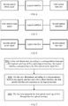
- FIG. 7 is a schematic flowchart of a data processing method according to an embodiment of the present invention.
- the data processing apparatus shown in FIG. 2 may be configured to execute the method shown in FIG. 7 .
- the method may include the following steps:
- the foregoing method further includes: modifying, by the line card, the bandwidth of the logical interface to second bandwidth, where the bandwidth of the first optical serial signal flow is less than or equal to the second bandwidth.
- the line card 100 may modify the bandwidth of the logical interface according to a configuration message sent by a network management system or according to a configuration command entered by an engineer by using telnet. Specifically, the bandwidth of the logical interface is modified to the second bandwidth.
- the line card 100 may modify the configuration information.
- An identifier of the logical interface and a value of the second bandwidth may be stored in the modified configuration information.
- the first bandwidth is not equal to the second bandwidth.
- the first bandwidth may be 25 gigabits per second (English: gigabit per second, Gb/s for short), and the second bandwidth may be 50 Gb/s.
- the correspondence between the first optical serial signal flow and the logical interface is stored in the first correspondence table, and the correspondence between the logical interface and the first optical interface is stored in a second correspondence table.
- the bandwidth of the logical interface is configured to be the first bandwidth, the bandwidth of the first optical serial signal flow is less than or equal to the first bandwidth, the logical interface is corresponding to the first optical interface, and the first optical interface is corresponding to an optical fiber, or a channel that is in an optical fiber and is used to transmit an optical signal with a wavelength.
- FIG. 3 shows the foregoing correspondences.
- the line card 100 may determine, according to the correspondence between the first optical serial signal flow and the logical interface, the logical interface corresponding to the first optical serial signal flow, determine, according to the correspondence between the logical interface and the first optical interface, the first optical interface corresponding to the logical interface, and transmit the first optical serial signal flow through the first optical interface.
- the wavelength may be 850 nanometers (English: nanometer, nm for short), 1310 nm, or 1550 nm.
- the line card 100 or a network device including the line card 100 may store the first correspondence table that is used to store the correspondence between the first optical serial signal flow and the logical interface; and may further store the second correspondence table that is used to store the correspondence between the logical interface and the first optical interface.
- the first optical interface is corresponding to an optical fiber, or a channel that is in an optical fiber and is used to transmit an optical signal with a wavelength.
- the first correspondence table may include an identifier of the first optical serial signal flow and the identifier of the logical interface
- the second correspondence table may include the identifier of the logical interface and an identifier of the first optical interface.
- the first optical serial signal flow may be sent by a first SerDes, where the line card 100 includes the first SerDes.
- the identifier of the first optical serial signal flow may be an identifier of the first SerDes.
- the line card 100 may generate the first correspondence table and the second correspondence table according to a configuration message sent by a network management system or according to a configuration command entered by an engineer by using telnet.
- the line card 100 may modify the first correspondence table and the second correspondence table according to a configuration message sent by a network management system or according to a configuration command entered by an engineer by using telnet.
- the line card 100 may perform configuration on the bandwidth of the logical interface.
- the line card 100 may perform configuration on the bandwidth of the logical interface according to a configuration message sent by a network management system or according to a configuration command entered by an engineer by using telnet.
- the bandwidth of the logical interface is configured to be the first bandwidth.
- the line card 100 may generate configuration information after the bandwidth of the logical interface is configured, where the identifier of the logical interface and a value of the first bandwidth may be stored in the configuration information.
- One signal flow of the logical interface may be modulated by a MAC/PCS chip in the line card into one or more electrical serial signal flows, and one electrical serial signal flow may be modulated by an optical modem in the line card into one or more optical serial signal flows, where bandwidth of an optical serial signal flow is less than or equal to bandwidth of a corresponding logical interface.
- the line card 100 may establish the first correspondence table and the second correspondence table when performing configuration on the logical interface, or the line card 100 may adjust the first correspondence table and the second correspondence table when adjusting the logical interface, for example, when adjusting a quantity of logical interfaces or adjusting the bandwidth of the logical interface, to meet a requirement of a flexible Ethernet.
- the foregoing method further includes:
- the correspondence between the second optical serial signal flow and the logical interface may be implemented by using, for example, a third correspondence table, where the third correspondence table may include an identifier of the second optical serial signal flow and the identifier of the logical interface.
- the second optical serial signal flow may be sent by a second SerDes, where the line card 100 includes the second SerDes.
- the identifier of the second optical serial signal flow may be an identifier of the second SerDes.
- a modification may be implemented by modifying the foregoing first correspondence table.
- the line card 100 modifies the correspondence between the first optical serial signal flow and the logical interface in the first correspondence table to the correspondence between the second optical serial signal flow and the logical interface, where the bandwidth of the second optical serial signal flow is less than or equal to the first bandwidth.
- FIG. 4 shows the modified correspondence.
- the line card 100 may determine, according to the correspondence between the second optical serial signal flow and the logical interface, the logical interface corresponding to the second optical serial signal flow, determine, according to the correspondence between the logical interface and the first optical interface, the first optical interface corresponding to the logical interface, and transmit the first optical serial signal flow through the first optical interface.
- a correspondence between a logical interface and an optical serial signal flow is modified by modifying the first correspondence table in the foregoing two correspondence tables, to change an optical serial signal flow that is input by an optical interface. Therefore, the foregoing technical solution may be better applied to a flexible Ethernet.
- the method may further include: modifying, by the line card, the bandwidth of the logical interface to second bandwidth, where the bandwidth of the second optical serial signal flow is less than or equal to the second bandwidth.
- the foregoing method further includes:
- a modification may be implemented by modifying the foregoing second correspondence table.
- the line card 100 modifies the correspondence between the first optical interface and the logical interface in the second correspondence table to the correspondence between the second optical interface and the logical interface.
- FIG. 5 shows the modified correspondence.
- the line card 100 may determine, according to the correspondence between the first optical serial signal flow and the logical interface, the logical interface corresponding to the first optical serial signal flow.
- the line card 100 may determine, according to the correspondence between the logical interface and the second optical interface, the second optical interface corresponding to the logical interface, and transmits the first optical serial signal flow through the second optical interface.
- a correspondence between a logical interface and an optical interface is modified by modifying the second correspondence table in the foregoing two correspondence tables, to change an optical interface that is used to output an optical serial signal flow. Therefore, the foregoing technical solution may be better applied to a flexible Ethernet.
- the method may further include: modifying, by the line card, the bandwidth of the logical interface to second bandwidth, where the bandwidth of the first optical serial signal flow is less than or equal to the second bandwidth.
- the foregoing method further includes:
- modifications may be implemented by modifying the foregoing first correspondence table and the second correspondence table.
- the line card 100 modifies the correspondence between the first optical serial signal flow and the logical interface in the first correspondence table to the correspondence between the second optical serial signal flow and the logical interface.
- the line card 100 modifies the correspondence between the logical interface and the first optical interface in the second correspondence table to the correspondence between the logical interface and the second optical interface.
- FIG. 6 shows the modified correspondence.
- the line card 100 determines, according to the correspondence between the second optical serial signal flow and the logical interface, the logical interface corresponding to the second optical serial signal flow, determines, according to the correspondence between the logical interface and the second optical interface, the second optical interface corresponding to the logical interface, and transmits the second optical serial signal flow through the second optical interface.
- a correspondence between a logical interface and an optical interface and a correspondence between the logical interface and an optical serial signal flow are modified by modifying the foregoing two correspondence tables, so that a current optical interface and a current optical serial signal flow may be changed. That is, another optical interface is used to output another optical serial signal. Therefore, the foregoing technical solution may be better applied to a flexible Ethernet.
- the foregoing method further includes: modifying, by the line card, the bandwidth of the logical interface to second bandwidth, where the bandwidth of the second optical serial signal flow is less than or equal to the second bandwidth.
- the second optical interface involved in the foregoing embodiment is corresponding to an optical fiber, or a channel that is in an optical fiber and is used to transmit an optical signal with a wavelength, where the second optical interface is different from the first optical interface.
- a first optical serial signal flow is corresponding to a logical interface
- the logical interface is corresponding to a first optical interface.
- An optical interface used to output the first optical serial signal flow may be determined according to a correspondence between the first optical serial signal flow and the logical interface and a correspondence between the logical interface and the first optical interface. Therefore, at least one of the foregoing two correspondences may be modified to change an optical serial signal flow that is output by an optical interface or change an optical interface that is used to output an optical serial signal flow. Therefore, the foregoing technical solution may be better applied to a flexible Ethernet.
- the embodiments of the present invention may be provided as a method, a system, or a computer program product. Therefore, the present invention may use a form of hardware only embodiments, software only embodiments, or embodiments with a combination of software and hardware. Moreover, the present invention may use a form of a computer program product that is implemented on one or more computer-usable storage media (including but not limited to a disk memory, a CD-ROM, an optical memory, and the like) that include computer-usable program code.
- computer-usable storage media including but not limited to a disk memory, a CD-ROM, an optical memory, and the like
- These computer program instructions may be provided for a general-purpose computer, a dedicated computer, an embedded processor, or a processor of any other programmable data processing device, so that the instructions executed by the computer or the processor of any other programmable data processing device may implement a specific function in one or more procedures in the flowcharts and/or in one or more blocks in the block diagrams.
- These computer program instructions may also be stored in a computer readable memory that can instruct the computer or any other programmable data processing device to work in a specific manner, so that the instructions stored in the computer readable memory generate an artifact that includes an instruction apparatus.
- the instruction apparatus implements a specific function in one or more procedures in the flowcharts and/or in one or more blocks in the block diagrams.
- These computer program instructions may also be loaded onto a computer or another programmable data processing device, so that a series of operations and steps are performed on the computer or the another programmable device, thereby generating computer-implemented processing. Therefore, the instructions executed on the computer or the another programmable device provide steps for implementing a specific function in one or more procedures in the flowcharts and/or in one or more blocks in the block diagrams.
Landscapes
- Engineering & Computer Science (AREA)
- Computer Networks & Wireless Communication (AREA)
- Signal Processing (AREA)
- Data Exchanges In Wide-Area Networks (AREA)
- Optical Communication System (AREA)
- Small-Scale Networks (AREA)
Claims (15)
- Vorrichtung zur Datenverarbeitung, umfassend eine Leitungskarte (100), wobei die Leitungskarte (100) Folgendes umfasst:ein erstes Verarbeitungsmodul (101), ausgelegt zum Bestimmen, gemäß einer Entsprechung zwischen einem ersten optischen seriellen Signalfluss und einer logischen Schnittstelle, der logischen Schnittstelle entsprechend dem ersten optischen seriellen Signalfluss, wobei eine Bandbreite der logischen Schnittstelle als eine erste Bandbreite ausgelegt ist, eine Bandbreite des ersten optischen seriellen Signalflusses kleiner als oder gleich der ersten Bandbreite ist, die logische Schnittstelle einer ersten optischen Schnittstelle entspricht und die erste optische Schnittstelle einer optischen Faser oder einem Kanal entspricht, der eine optische Faser ist und verwendet wird, um ein optisches Signal mit einer Wellenlänge zu übertragen;ein zweites Verarbeitungsmodul (102), ausgelegt zum Bestimmen, gemäß einer Entsprechung zwischen der logischen Schnittstelle und der ersten optischen Schnittstelle und der logischen Schnittstelle, die durch das erste Verarbeitungsmodul (101) bestimmt wird, wobei die erste optische Schnittstelle der logischen Schnittstelle entspricht; undein Zeitsteuerungsmodul (103), ausgelegt zum Übertragen des ersten optischen seriellen Signalflusses durch die erste optische Schnittstelle, bestimmt durch das zweite Verarbeitungsmodul (102).
- Vorrichtung nach Anspruch 1, wobei:
das erste Verarbeitungsmodul (101) ferner ausgelegt ist zum:Modifizieren der Entsprechung zwischen dem ersten optischen seriellen Signalfluss und der logischen Schnittstelle zu einer Entsprechung zwischen einem zweiten optischen seriellen Signalfluss und der logischen Schnittstelle, wobei eine Bandbreite des zweiten optischen seriellen Signalflusses kleiner als oder gleich der ersten Bandbreite ist; undBestimmen, gemäß der Entsprechung zwischen dem zweiten optischen seriellen Signalfluss und der logischen Schnittstelle, der logischen Schnittstelle entsprechend dem zweiten optischen seriellen Signalfluss; unddas Zeitsteuerungsmodul (103) ferner ausgelegt ist zum Übertragen des zweiten optischen seriellen Signalflusses durch die erste optische Schnittstelle, bestimmt durch das zweite Verarbeitungsmodul (102). - Vorrichtung nach Anspruch 2, wobei:
das erste Verarbeitungsmodul (101) ferner ausgelegt ist zum Modifizieren der Bandbreite der logischen Schnittstelle zu einer zweiten Bandbreite, wobei die Bandbreite des zweiten optischen seriellen Signalflusses kleiner als oder gleich der zweiten Bandbreite ist. - Vorrichtung nach Anspruch 1, wobei:
das zweite Verarbeitungsmodul (102) ferner ausgelegt ist zum:Modifizieren der Entsprechung zwischen der logischen Schnittstelle und der ersten optischen Schnittstelle zu einer Entsprechung zwischen der logischen Schnittstelle und einer zweiten optischen Schnittstelle; undBestimmen, gemäß der Entsprechung zwischen der logischen Schnittstelle und der zweiten optischen Schnittstelle, der zweiten optischen Schnittstelle entsprechend der logischen Schnittstelle; unddas Zeitsteuerungsmodul (103) ferner ausgelegt ist zum:
Übertragen des ersten optischen seriellen Signalflusses durch die zweite optische Schnittstelle, bestimmt durch das zweite Verarbeitungsmodul (102). - Vorrichtung nach Anspruch 4, wobei:
das zweite Verarbeitungsmodul (102) ferner ausgelegt ist zum Modifizieren der Bandbreite der logischen Schnittstelle zu einer zweiten Bandbreite, wobei die Bandbreite des ersten optischen seriellen Signalflusses kleiner als oder gleich der zweiten Bandbreite ist. - Vorrichtung nach Anspruch 1, wobei:
das erste Verarbeitungsmodul (101) ferner ausgelegt ist zum:Modifizieren der Entsprechung zwischen dem ersten optischen seriellen Signalfluss und der logischen Schnittstelle zu einer Entsprechung zwischen einem zweiten optischen seriellen Signalfluss und der logischen Schnittstelle; undBestimmen, gemäß der Entsprechung zwischen dem zweiten optischen seriellen Signalfluss und der logischen Schnittstelle, der logischen Schnittstelle entsprechend dem zweiten optischen seriellen Signalfluss;das zweite Verarbeitungsmodul (102) ferner ausgelegt ist zum:Modifizieren der Entsprechung zwischen der logischen Schnittstelle und der ersten optischen Schnittstelle zu einer Entsprechung zwischen der logischen Schnittstelle und einer zweiten optischen Schnittstelle; undBestimmen, gemäß der Entsprechung zwischen der logischen Schnittstelle und der zweiten optischen Schnittstelle und der logischen Schnittstelle, die durch das erste Verarbeitungsmodul (101) bestimmt wird, wobei die zweite optische Schnittstelle der logischen Schnittstelle entspricht; unddas Zeitsteuerungsmodul ferner ausgelegt ist zum:
Übertragen des zweiten optischen seriellen Signalflusses durch die zweite optische Schnittstelle, bestimmt durch das zweite Verarbeitungsmodul (102). - Vorrichtung nach Anspruch 6, wobei:
das erste Verarbeitungsmodul (101) oder das zweite Verarbeitungsmodul (102) ferner ausgelegt ist zum:
Modifizieren der Bandbreite der logischen Schnittstelle zu einer zweiten Bandbreite, wobei die Bandbreite des zweiten optischen seriellen Signalflusses kleiner als oder gleich der zweiten Bandbreite ist. - Vorrichtung nach Anspruch 1, wobei:
das erste Verarbeitungsmodul (101) oder das zweite Verarbeitungsmodul (102) ferner ausgelegt ist zum:
Modifizieren der Bandbreite der logischen Schnittstelle zu einer zweiten Bandbreite, wobei die Bandbreite des ersten optischen seriellen Signalflusses kleiner als oder gleich der zweiten Bandbreite ist. - Verfahren zur Datenverarbeitung, das Folgendes umfasst:Bestimmen (S201), durch eine Leitungskarte, gemäß einer Entsprechung zwischen einem ersten optischen seriellen Signalfluss und einer logischen Schnittstelle, der logischen Schnittstelle entsprechend dem ersten optischen seriellen Signalfluss, wobei eine Bandbreite der logischen Schnittstelle als eine erste Bandbreite ausgelegt ist, eine Bandbreite des ersten optischen seriellen Signalflusses kleiner als oder gleich der ersten Bandbreite ist, die logische Schnittstelle einer ersten optischen Schnittstelle entspricht und die erste optische Schnittstelle einer optischen Faser oder einem Kanal entspricht, der eine optische Faser ist und verwendet wird, um ein optisches Signal mit einer Wellenlänge zu übertragen;Bestimmen (S201), durch eine Leitungskarte, gemäß einer Entsprechung zwischen der logischen Schnittstelle und der ersten optischen Schnittstelle, der ersten optischen Schnittstelle entsprechend der logischen Schnittstelle; undÜbertragen (S203), durch die Leitungskarte, des ersten optischen seriellen Signalflusses durch die erste optische Schnittstelle.
- Verfahren nach Anspruch 9, wobei das Verfahren ferner Folgendes umfasst:Modifizieren, durch die Leitungskarte, der Entsprechung zwischen dem ersten optischen seriellen Signalfluss und der logischen Schnittstelle zu einer Entsprechung zwischen einem zweiten optischen seriellen Signalfluss und der logischen Schnittstelle, wobei eine Bandbreite des zweiten optischen seriellen Signalflusses kleiner als oder gleich der ersten Bandbreite ist;Bestimmen, durch die Leitungskarte, gemäß der Entsprechung zwischen dem zweiten optischen seriellen Signalfluss und der logischen Schnittstelle, der logischen Schnittstelle entsprechend dem zweiten optischen seriellen Signalfluss; undÜbertragen, durch die Leitungskarte, des zweiten optischen seriellen Signalflusses durch die erste optische Schnittstelle.
- Verfahren nach Anspruch 10, wobei das Verfahren ferner Folgendes umfasst:
Modifizieren, durch die Leitungskarte, der Bandbreite der logischen Schnittstelle zu einer zweiten Bandbreite, wobei die Bandbreite des zweiten optischen seriellen Signalflusses kleiner als oder gleich der zweiten Bandbreite ist. - Verfahren nach Anspruch 9, wobei das Verfahren ferner Folgendes umfasst:Modifizieren, durch die Leitungskarte, der Entsprechung zwischen der logischen Schnittstelle und der ersten optischen Schnittstelle zu einer Entsprechung zwischen der logischen Schnittstelle und einer zweiten optischen Schnittstelle;Bestimmen, durch die Leitungskarte, gemäß der Entsprechung zwischen der logischen Schnittstelle und der zweiten optischen Schnittstelle, der zweiten optischen Schnittstelle entsprechend der logischen Schnittstelle; undÜbertragen, durch die Leitungskarte, des ersten optischen seriellen Signalflusses durch die zweite optische Schnittstelle.
- Verfahren nach Anspruch 12, wobei das Verfahren ferner Folgendes umfasst:
Modifizieren, durch die Leitungskarte, der Bandbreite der logischen Schnittstelle zu einer zweiten Bandbreite, wobei die Bandbreite des ersten optischen seriellen Signalflusses kleiner als oder gleich der zweiten Bandbreite ist. - Verfahren nach Anspruch 9, wobei das Verfahren ferner Folgendes umfasst:Modifizieren, durch die Leitungskarte, der Entsprechung zwischen dem ersten optischen seriellen Signalfluss und der logischen Schnittstelle zu einer Entsprechung zwischen einem zweiten optischen seriellen Signalfluss und der logischen Schnittstelle;Modifizieren, durch die Leitungskarte, der Entsprechung zwischen der logischen Schnittstelle und der ersten optischen Schnittstelle zu einer Entsprechung zwischen der logischen Schnittstelle und einer zweiten optischen Schnittstelle;Bestimmen, durch die Leitungskarte, gemäß der Entsprechung zwischen dem zweiten optischen seriellen Signalfluss und der logischen Schnittstelle, der logischen Schnittstelle entsprechend dem zweiten optischen seriellen Signalfluss;Bestimmen, durch die Leitungskarte, gemäß der Entsprechung zwischen der logischen Schnittstelle und der zweiten optischen Schnittstelle, der zweiten optischen Schnittstelle entsprechend der logischen Schnittstelle; undÜbertragen, durch die Leitungskarte, des zweiten optischen seriellen Signalflusses durch die zweite optische Schnittstelle.
- Verfahren nach Anspruch 14, wobei das Verfahren ferner Folgendes umfasst:
Modifizieren, durch die Leitungskarte, der Bandbreite der logischen Schnittstelle zu einer zweiten Bandbreite, wobei die Bandbreite des zweiten optischen seriellen Signalflusses kleiner als oder gleich der zweiten Bandbreite ist.
Applications Claiming Priority (1)
| Application Number | Priority Date | Filing Date | Title |
|---|---|---|---|
| PCT/CN2014/081213 WO2016000146A1 (zh) | 2014-06-30 | 2014-06-30 | 一种数据处理方法及装置 |
Publications (3)
| Publication Number | Publication Date |
|---|---|
| EP3148209A1 EP3148209A1 (de) | 2017-03-29 |
| EP3148209A4 EP3148209A4 (de) | 2017-06-14 |
| EP3148209B1 true EP3148209B1 (de) | 2019-08-21 |
Family
ID=55018240
Family Applications (1)
| Application Number | Title | Priority Date | Filing Date |
|---|---|---|---|
| EP14896611.2A Active EP3148209B1 (de) | 2014-06-30 | 2014-06-30 | Verfahren und vorrichtung zur datenverarbeitung |
Country Status (5)
| Country | Link |
|---|---|
| US (1) | US10187708B2 (de) |
| EP (1) | EP3148209B1 (de) |
| CN (2) | CN106464990B (de) |
| ES (1) | ES2753270T3 (de) |
| WO (1) | WO2016000146A1 (de) |
Families Citing this family (3)
| Publication number | Priority date | Publication date | Assignee | Title |
|---|---|---|---|---|
| CN107204941A (zh) * | 2016-03-18 | 2017-09-26 | 中兴通讯股份有限公司 | 一种灵活以太网路径建立的方法和装置 |
| CN110099932A (zh) | 2016-12-16 | 2019-08-06 | 诺佛赛特有限责任公司 | 树脂组合物 |
| CN109302372B (zh) | 2017-07-24 | 2021-02-23 | 华为技术有限公司 | 一种通信方法、设备及存储介质 |
Family Cites Families (15)
| Publication number | Priority date | Publication date | Assignee | Title |
|---|---|---|---|---|
| DK1021901T3 (da) * | 1997-10-10 | 2010-03-08 | Daphimo Co B V Llc | Splitterløst multibærermodem |
| AU2001284907A1 (en) * | 2000-08-15 | 2002-02-25 | Nortel Networks Limited | System, device, and method for managing communication services in an optical communication system |
| CN100536406C (zh) * | 2006-11-24 | 2009-09-02 | 中兴通讯股份有限公司 | 一种接口索引方法和系统 |
| CN101207490A (zh) * | 2006-12-21 | 2008-06-25 | 中兴通讯股份有限公司 | 自适应切换以太网带宽的方法 |
| CN101207489A (zh) * | 2006-12-21 | 2008-06-25 | 中兴通讯股份有限公司 | 以太网交换系统 |
| CN101207491B (zh) * | 2006-12-21 | 2011-03-16 | 中兴通讯股份有限公司 | 用于以太网系统的带宽自适应切换装置和方法 |
| US8089993B2 (en) | 2008-09-09 | 2012-01-03 | Nec Laboratories America, Inc. | Sliceable router with packet over optical OFDM transmission |
| CN101583054A (zh) * | 2009-06-12 | 2009-11-18 | 中兴通讯股份有限公司 | 利用光模块实现光接口支持多种速率模式的方法及装置 |
| US8910230B2 (en) * | 2010-01-22 | 2014-12-09 | Gainspeed, Inc. | Method of transforming HFC CATV analog fiber transmission to digital fiber transmission |
| CN101840332B (zh) * | 2010-03-09 | 2014-03-05 | 北京握奇数据系统有限公司 | 一种java智能卡的数据处理方法、装置及系统 |
| US20110229126A1 (en) * | 2010-03-18 | 2011-09-22 | Cisco Technology, Inc. | Automatic Adjustment of Optical Bandwidth Based on Client Layer Needs |
| CN102971996B (zh) * | 2010-07-09 | 2016-08-03 | 瑞典爱立信有限公司 | 带有分组突发的负载平衡的交换节点 |
| CN102143006B (zh) * | 2011-04-18 | 2013-09-18 | 福建星网锐捷网络有限公司 | 通讯设备中的接口拓扑控制方法、系统及装置 |
| WO2012106939A1 (zh) * | 2011-07-27 | 2012-08-16 | 华为技术有限公司 | 一种高速光传输系统、设备及数据处理方法 |
| EP2670082A4 (de) * | 2011-08-23 | 2014-02-19 | Huawei Tech Co Ltd | Multichassis-kaskadenvorrichtung |
-
2014
- 2014-06-30 CN CN201480079292.0A patent/CN106464990B/zh active Active
- 2014-06-30 WO PCT/CN2014/081213 patent/WO2016000146A1/zh not_active Ceased
- 2014-06-30 ES ES14896611T patent/ES2753270T3/es active Active
- 2014-06-30 EP EP14896611.2A patent/EP3148209B1/de active Active
- 2014-06-30 CN CN201910883675.8A patent/CN110752878B/zh active Active
-
2016
- 2016-12-29 US US15/393,348 patent/US10187708B2/en active Active
Non-Patent Citations (1)
| Title |
|---|
| None * |
Also Published As
| Publication number | Publication date |
|---|---|
| EP3148209A4 (de) | 2017-06-14 |
| CN110752878B (zh) | 2022-12-13 |
| CN106464990B (zh) | 2019-11-12 |
| US10187708B2 (en) | 2019-01-22 |
| ES2753270T3 (es) | 2020-04-07 |
| US20170111718A1 (en) | 2017-04-20 |
| WO2016000146A1 (zh) | 2016-01-07 |
| EP3148209A1 (de) | 2017-03-29 |
| CN110752878A (zh) | 2020-02-04 |
| CN106464990A (zh) | 2017-02-22 |
Similar Documents
| Publication | Publication Date | Title |
|---|---|---|
| US20210051070A1 (en) | Apparatus and method for a unified slice manager | |
| US9360885B2 (en) | Fabric multipathing based on dynamic latency-based calculations | |
| US11637665B2 (en) | Forwarding table generation method and forwarding device | |
| US9893874B2 (en) | Fabric multipathing based on dynamic latency-based calculations | |
| CN110661636A (zh) | 用于获取网络切片的方法、装置和系统 | |
| US8462636B2 (en) | Systems and methods for communication of management traffic over link aggregation group interface for a network element with distributed architecture | |
| CN110506411A (zh) | 基于逻辑端口标识符管理虚拟交换机中的网络流量 | |
| US10454711B2 (en) | Method for obtaining port path and apparatus | |
| US9473833B2 (en) | Systems and methods for increasing bandwidth in a computer network | |
| US11770327B2 (en) | Data distribution method, data aggregation method, and related apparatuses | |
| KR20170019594A (ko) | 네트워크에서 통신 노드의 동작 방법 | |
| US20190260640A1 (en) | Port auto-negotiation method and device | |
| EP3148209B1 (de) | Verfahren und vorrichtung zur datenverarbeitung | |
| CN109392013A (zh) | 一种服务质量QoS的调整方法及通信装置 | |
| US20160352607A1 (en) | Method and controller for announcing bandwidth of cluster system | |
| WO2014064976A1 (ja) | ネットワーク機器、制御方法、及びプログラム | |
| US10382250B2 (en) | Information processing system and control method for information processing system | |
| US8467395B1 (en) | Method and system for link aggregation | |
| KR20160065010A (ko) | Sdn 환경에서 서비스 기능 체이닝을 위한 oam 메시지 전송 방법 및 시스템 | |
| CN116939723A (zh) | 移动通信系统、方法、网元及确定性网络系统 | |
| JP2007019592A (ja) | 光加入者線終端装置、光加入者線端局装置および帯域要求方法 | |
| CN104579897A (zh) | 一种帧通路配置方法、装置及系统 |
Legal Events
| Date | Code | Title | Description |
|---|---|---|---|
| STAA | Information on the status of an ep patent application or granted ep patent |
Free format text: STATUS: THE INTERNATIONAL PUBLICATION HAS BEEN MADE |
|
| PUAI | Public reference made under article 153(3) epc to a published international application that has entered the european phase |
Free format text: ORIGINAL CODE: 0009012 |
|
| STAA | Information on the status of an ep patent application or granted ep patent |
Free format text: STATUS: REQUEST FOR EXAMINATION WAS MADE |
|
| 17P | Request for examination filed |
Effective date: 20161222 |
|
| AK | Designated contracting states |
Kind code of ref document: A1 Designated state(s): AL AT BE BG CH CY CZ DE DK EE ES FI FR GB GR HR HU IE IS IT LI LT LU LV MC MK MT NL NO PL PT RO RS SE SI SK SM TR |
|
| AX | Request for extension of the european patent |
Extension state: BA ME |
|
| A4 | Supplementary search report drawn up and despatched |
Effective date: 20170515 |
|
| RIC1 | Information provided on ipc code assigned before grant |
Ipc: H04Q 11/00 20060101AFI20170509BHEP Ipc: H04L 12/935 20130101ALI20170509BHEP |
|
| DAX | Request for extension of the european patent (deleted) | ||
| GRAP | Despatch of communication of intention to grant a patent |
Free format text: ORIGINAL CODE: EPIDOSNIGR1 |
|
| STAA | Information on the status of an ep patent application or granted ep patent |
Free format text: STATUS: GRANT OF PATENT IS INTENDED |
|
| INTG | Intention to grant announced |
Effective date: 20190305 |
|
| GRAS | Grant fee paid |
Free format text: ORIGINAL CODE: EPIDOSNIGR3 |
|
| GRAA | (expected) grant |
Free format text: ORIGINAL CODE: 0009210 |
|
| STAA | Information on the status of an ep patent application or granted ep patent |
Free format text: STATUS: THE PATENT HAS BEEN GRANTED |
|
| AK | Designated contracting states |
Kind code of ref document: B1 Designated state(s): AL AT BE BG CH CY CZ DE DK EE ES FI FR GB GR HR HU IE IS IT LI LT LU LV MC MK MT NL NO PL PT RO RS SE SI SK SM TR |
|
| REG | Reference to a national code |
Ref country code: GB Ref legal event code: FG4D |
|
| REG | Reference to a national code |
Ref country code: CH Ref legal event code: EP |
|
| REG | Reference to a national code |
Ref country code: DE Ref legal event code: R096 Ref document number: 602014052350 Country of ref document: DE |
|
| REG | Reference to a national code |
Ref country code: AT Ref legal event code: REF Ref document number: 1171099 Country of ref document: AT Kind code of ref document: T Effective date: 20190915 |
|
| REG | Reference to a national code |
Ref country code: IE Ref legal event code: FG4D |
|
| REG | Reference to a national code |
Ref country code: LT Ref legal event code: MG4D |
|
| REG | Reference to a national code |
Ref country code: NL Ref legal event code: MP Effective date: 20190821 |
|
| PG25 | Lapsed in a contracting state [announced via postgrant information from national office to epo] |
Ref country code: NL Free format text: LAPSE BECAUSE OF FAILURE TO SUBMIT A TRANSLATION OF THE DESCRIPTION OR TO PAY THE FEE WITHIN THE PRESCRIBED TIME-LIMIT Effective date: 20190821 Ref country code: BG Free format text: LAPSE BECAUSE OF FAILURE TO SUBMIT A TRANSLATION OF THE DESCRIPTION OR TO PAY THE FEE WITHIN THE PRESCRIBED TIME-LIMIT Effective date: 20191121 Ref country code: HR Free format text: LAPSE BECAUSE OF FAILURE TO SUBMIT A TRANSLATION OF THE DESCRIPTION OR TO PAY THE FEE WITHIN THE PRESCRIBED TIME-LIMIT Effective date: 20190821 Ref country code: SE Free format text: LAPSE BECAUSE OF FAILURE TO SUBMIT A TRANSLATION OF THE DESCRIPTION OR TO PAY THE FEE WITHIN THE PRESCRIBED TIME-LIMIT Effective date: 20190821 Ref country code: FI Free format text: LAPSE BECAUSE OF FAILURE TO SUBMIT A TRANSLATION OF THE DESCRIPTION OR TO PAY THE FEE WITHIN THE PRESCRIBED TIME-LIMIT Effective date: 20190821 Ref country code: NO Free format text: LAPSE BECAUSE OF FAILURE TO SUBMIT A TRANSLATION OF THE DESCRIPTION OR TO PAY THE FEE WITHIN THE PRESCRIBED TIME-LIMIT Effective date: 20191121 Ref country code: PT Free format text: LAPSE BECAUSE OF FAILURE TO SUBMIT A TRANSLATION OF THE DESCRIPTION OR TO PAY THE FEE WITHIN THE PRESCRIBED TIME-LIMIT Effective date: 20191223 Ref country code: LT Free format text: LAPSE BECAUSE OF FAILURE TO SUBMIT A TRANSLATION OF THE DESCRIPTION OR TO PAY THE FEE WITHIN THE PRESCRIBED TIME-LIMIT Effective date: 20190821 |
|
| PG25 | Lapsed in a contracting state [announced via postgrant information from national office to epo] |
Ref country code: LV Free format text: LAPSE BECAUSE OF FAILURE TO SUBMIT A TRANSLATION OF THE DESCRIPTION OR TO PAY THE FEE WITHIN THE PRESCRIBED TIME-LIMIT Effective date: 20190821 Ref country code: RS Free format text: LAPSE BECAUSE OF FAILURE TO SUBMIT A TRANSLATION OF THE DESCRIPTION OR TO PAY THE FEE WITHIN THE PRESCRIBED TIME-LIMIT Effective date: 20190821 Ref country code: IS Free format text: LAPSE BECAUSE OF FAILURE TO SUBMIT A TRANSLATION OF THE DESCRIPTION OR TO PAY THE FEE WITHIN THE PRESCRIBED TIME-LIMIT Effective date: 20191221 Ref country code: GR Free format text: LAPSE BECAUSE OF FAILURE TO SUBMIT A TRANSLATION OF THE DESCRIPTION OR TO PAY THE FEE WITHIN THE PRESCRIBED TIME-LIMIT Effective date: 20191122 Ref country code: AL Free format text: LAPSE BECAUSE OF FAILURE TO SUBMIT A TRANSLATION OF THE DESCRIPTION OR TO PAY THE FEE WITHIN THE PRESCRIBED TIME-LIMIT Effective date: 20190821 |
|
| REG | Reference to a national code |
Ref country code: AT Ref legal event code: MK05 Ref document number: 1171099 Country of ref document: AT Kind code of ref document: T Effective date: 20190821 |
|
| PG25 | Lapsed in a contracting state [announced via postgrant information from national office to epo] |
Ref country code: TR Free format text: LAPSE BECAUSE OF FAILURE TO SUBMIT A TRANSLATION OF THE DESCRIPTION OR TO PAY THE FEE WITHIN THE PRESCRIBED TIME-LIMIT Effective date: 20190821 |
|
| REG | Reference to a national code |
Ref country code: ES Ref legal event code: FG2A Ref document number: 2753270 Country of ref document: ES Kind code of ref document: T3 Effective date: 20200407 |
|
| PG25 | Lapsed in a contracting state [announced via postgrant information from national office to epo] |
Ref country code: DK Free format text: LAPSE BECAUSE OF FAILURE TO SUBMIT A TRANSLATION OF THE DESCRIPTION OR TO PAY THE FEE WITHIN THE PRESCRIBED TIME-LIMIT Effective date: 20190821 Ref country code: PL Free format text: LAPSE BECAUSE OF FAILURE TO SUBMIT A TRANSLATION OF THE DESCRIPTION OR TO PAY THE FEE WITHIN THE PRESCRIBED TIME-LIMIT Effective date: 20190821 Ref country code: RO Free format text: LAPSE BECAUSE OF FAILURE TO SUBMIT A TRANSLATION OF THE DESCRIPTION OR TO PAY THE FEE WITHIN THE PRESCRIBED TIME-LIMIT Effective date: 20190821 Ref country code: EE Free format text: LAPSE BECAUSE OF FAILURE TO SUBMIT A TRANSLATION OF THE DESCRIPTION OR TO PAY THE FEE WITHIN THE PRESCRIBED TIME-LIMIT Effective date: 20190821 Ref country code: IT Free format text: LAPSE BECAUSE OF FAILURE TO SUBMIT A TRANSLATION OF THE DESCRIPTION OR TO PAY THE FEE WITHIN THE PRESCRIBED TIME-LIMIT Effective date: 20190821 Ref country code: AT Free format text: LAPSE BECAUSE OF FAILURE TO SUBMIT A TRANSLATION OF THE DESCRIPTION OR TO PAY THE FEE WITHIN THE PRESCRIBED TIME-LIMIT Effective date: 20190821 |
|
| PG25 | Lapsed in a contracting state [announced via postgrant information from national office to epo] |
Ref country code: SM Free format text: LAPSE BECAUSE OF FAILURE TO SUBMIT A TRANSLATION OF THE DESCRIPTION OR TO PAY THE FEE WITHIN THE PRESCRIBED TIME-LIMIT Effective date: 20190821 Ref country code: CZ Free format text: LAPSE BECAUSE OF FAILURE TO SUBMIT A TRANSLATION OF THE DESCRIPTION OR TO PAY THE FEE WITHIN THE PRESCRIBED TIME-LIMIT Effective date: 20190821 Ref country code: IS Free format text: LAPSE BECAUSE OF FAILURE TO SUBMIT A TRANSLATION OF THE DESCRIPTION OR TO PAY THE FEE WITHIN THE PRESCRIBED TIME-LIMIT Effective date: 20200224 Ref country code: SK Free format text: LAPSE BECAUSE OF FAILURE TO SUBMIT A TRANSLATION OF THE DESCRIPTION OR TO PAY THE FEE WITHIN THE PRESCRIBED TIME-LIMIT Effective date: 20190821 |
|
| REG | Reference to a national code |
Ref country code: DE Ref legal event code: R097 Ref document number: 602014052350 Country of ref document: DE |
|
| PLBE | No opposition filed within time limit |
Free format text: ORIGINAL CODE: 0009261 |
|
| STAA | Information on the status of an ep patent application or granted ep patent |
Free format text: STATUS: NO OPPOSITION FILED WITHIN TIME LIMIT |
|
| PG2D | Information on lapse in contracting state deleted |
Ref country code: IS |
|
| 26N | No opposition filed |
Effective date: 20200603 |
|
| PG25 | Lapsed in a contracting state [announced via postgrant information from national office to epo] |
Ref country code: SI Free format text: LAPSE BECAUSE OF FAILURE TO SUBMIT A TRANSLATION OF THE DESCRIPTION OR TO PAY THE FEE WITHIN THE PRESCRIBED TIME-LIMIT Effective date: 20190821 |
|
| PG25 | Lapsed in a contracting state [announced via postgrant information from national office to epo] |
Ref country code: MC Free format text: LAPSE BECAUSE OF FAILURE TO SUBMIT A TRANSLATION OF THE DESCRIPTION OR TO PAY THE FEE WITHIN THE PRESCRIBED TIME-LIMIT Effective date: 20190821 |
|
| REG | Reference to a national code |
Ref country code: CH Ref legal event code: PL |
|
| PG25 | Lapsed in a contracting state [announced via postgrant information from national office to epo] |
Ref country code: LU Free format text: LAPSE BECAUSE OF NON-PAYMENT OF DUE FEES Effective date: 20200630 |
|
| REG | Reference to a national code |
Ref country code: BE Ref legal event code: MM Effective date: 20200630 |
|
| PG25 | Lapsed in a contracting state [announced via postgrant information from national office to epo] |
Ref country code: LI Free format text: LAPSE BECAUSE OF NON-PAYMENT OF DUE FEES Effective date: 20200630 Ref country code: IE Free format text: LAPSE BECAUSE OF NON-PAYMENT OF DUE FEES Effective date: 20200630 Ref country code: CH Free format text: LAPSE BECAUSE OF NON-PAYMENT OF DUE FEES Effective date: 20200630 |
|
| PG25 | Lapsed in a contracting state [announced via postgrant information from national office to epo] |
Ref country code: BE Free format text: LAPSE BECAUSE OF NON-PAYMENT OF DUE FEES Effective date: 20200630 |
|
| PG25 | Lapsed in a contracting state [announced via postgrant information from national office to epo] |
Ref country code: MT Free format text: LAPSE BECAUSE OF FAILURE TO SUBMIT A TRANSLATION OF THE DESCRIPTION OR TO PAY THE FEE WITHIN THE PRESCRIBED TIME-LIMIT Effective date: 20190821 Ref country code: CY Free format text: LAPSE BECAUSE OF FAILURE TO SUBMIT A TRANSLATION OF THE DESCRIPTION OR TO PAY THE FEE WITHIN THE PRESCRIBED TIME-LIMIT Effective date: 20190821 |
|
| PG25 | Lapsed in a contracting state [announced via postgrant information from national office to epo] |
Ref country code: MK Free format text: LAPSE BECAUSE OF FAILURE TO SUBMIT A TRANSLATION OF THE DESCRIPTION OR TO PAY THE FEE WITHIN THE PRESCRIBED TIME-LIMIT Effective date: 20190821 |
|
| PGFP | Annual fee paid to national office [announced via postgrant information from national office to epo] |
Ref country code: DE Payment date: 20250507 Year of fee payment: 12 |
|
| PGFP | Annual fee paid to national office [announced via postgrant information from national office to epo] |
Ref country code: GB Payment date: 20250508 Year of fee payment: 12 |
|
| PGFP | Annual fee paid to national office [announced via postgrant information from national office to epo] |
Ref country code: FR Payment date: 20250508 Year of fee payment: 12 |
|
| PGFP | Annual fee paid to national office [announced via postgrant information from national office to epo] |
Ref country code: ES Payment date: 20250707 Year of fee payment: 12 |