EP3148218A1 - Akustisches modul mit akustischem filter - Google Patents
Akustisches modul mit akustischem filter Download PDFInfo
- Publication number
- EP3148218A1 EP3148218A1 EP16189013.2A EP16189013A EP3148218A1 EP 3148218 A1 EP3148218 A1 EP 3148218A1 EP 16189013 A EP16189013 A EP 16189013A EP 3148218 A1 EP3148218 A1 EP 3148218A1
- Authority
- EP
- European Patent Office
- Prior art keywords
- acoustical
- pressure pick
- points
- module according
- module
- Prior art date
- Legal status (The legal status is an assumption and is not a legal conclusion. Google has not performed a legal analysis and makes no representation as to the accuracy of the status listed.)
- Granted
Links
Images


Classifications
-
- H—ELECTRICITY
- H04—ELECTRIC COMMUNICATION TECHNIQUE
- H04R—LOUDSPEAKERS, MICROPHONES, GRAMOPHONE PICK-UPS OR LIKE ACOUSTIC ELECTROMECHANICAL TRANSDUCERS; ELECTRIC HEARING AIDS; PUBLIC ADDRESS SYSTEMS
- H04R25/00—Electric hearing aids
- H04R25/40—Arrangements for obtaining a desired directivity characteristic
- H04R25/405—Arrangements for obtaining a desired directivity characteristic by combining a plurality of transducers
Definitions
- the present invention relates to an acoustical module configured to separate sound pressure signals from external sources.
- the present invention relates to an acoustical module where the influence of self-generated signals is attenuated.
- US 8,259,976 where an assembly comprising a sound emitter and at least two sound detectors fixed to each other is disclosed. Each detector has a sound receiving opening. The sound receiving openings of at least two of the detectors point in opposite directions.
- a feedback suppression algorithm for reducing the influence of self-generated signals, such as acoustic signals and vibration signals.
- Such self-generated signals may involve acoustical signals and vibration signals.
- an acoustical module comprising
- the acoustical module of the present invention is thus adapted to receive incoming acoustical pressure signals via a plurality of microphone units and regenerate the received signal via the receiver unit.
- the acoustical module of the present invention may be applicable in relation to hearing devices, such as various types of hearing aids.
- pressure pick-up points are to be understood as openings and/or holes through which incoming acoustical pressure signals are allowed to enter the acoustical module.
- at least one microphone unit may be acoustically connected to each of the pressure pick-up points.
- acoustical pressure signals are to be understood as acoustical sound/audio signals representing for example speech, music etc.
- the receiver unit may comprise a single receiver or a plurality of receivers.
- a single receiver a single acoustical signal and a signal vibration signal is generated.
- a plurality of receivers may collectively generate both acoustical signals and vibration signals. The contribution of all receivers may be combined into a total acoustic signal and a total vibration signal.
- the acoustical filter may advantageously be positioned between the first and the second acoustical pressure pick-up points. In this manner an incoming acoustical signal may be attenuated upon passing the acoustical filter so that the acoustical pressure pick-up points receive an incoming acoustical signal with different strengths.
- a first microphone unit may be acoustically connected to the first acoustical pressure pick-up point
- a second microphone unit may be acoustically connected to the second acoustical pressure pick-up point.
- the acoustical filter may form a dome shaped structure or at least a part of a dome shaped structure. Alternatively, it may be attached to a dome shaped structure. Dome shaped structures may exhibit additional properties in relation to the acoustical module. Such additional properties may include proper fixation of the acoustical module in an ear channel.
- the acoustical filter may form part of, or being attached to, an element which is adapted to support fixation of the acoustical module in an ear channel.
- the acoustical module may further comprise one or more additional domes or elements for additional support of the fixation of the acoustical module in the ear channel.
- the acoustical module may further comprise an additional acoustical filter and a third acoustical pressure pick-up point being acoustically connected to a microphone unit.
- the additional acoustical filter may either be positioned between the second and the third acoustical pressure pick-up points or between the first and second pressure pick-up points.
- acoustical filters can be placed between all off the pressure pick-up points. By applying more than two acoustical pressure pick-up points the suppression of the unwanted signals can be further improved.
- the reconstruction of the head-related transfer function (HRTF) could be at least partly achieved which is otherwise lost due to the fact that the microphone units are not at the exact position of the ear drum.
- additional acoustical pressure pick-up points may also be used to generate another desired directionality of the acoustical module.
- the additional acoustical filter may form part of a dome shaped structure or it may be attached to a dome shaped structure being shaped in a manner so that it supports fixation of the acoustical module in an ear channel.
- the plurality of microphone units may comprise omni-directional microphone units and/or directional microphone units.
- a sleeve may be provided to ease fixation of a dome to the exterior of the acoustical module.
- the dome may either comprise or have an acoustical filter attached thereto.
- the sleeve may be manufactured using an injection mouldable material, such as a polymer material.
- the sleeve and the dome form a one-piece component.
- the plurality of acoustical pressure pick-up points may act as one or more venting holes for the receiver unit.
- the acoustical module comprises for example two acoustical pressure pick-up points a single or both of these pressure pick-up points may be used for venting the receiver unit.
- the acoustical module comprises for example three acoustical pressure pick-up points one, two or three pressure pick-up points may be used for venting the receiver unit.
- a plurality of dedicated venting holes may act as one or more venting holes for the receiver unit may be provided.
- the acoustical module may further comprise a protection arrangement for preventing dust or other impurities to enter the plurality of acoustical pressure pick-up points.
- the protection arrangement may comprise a number of barrier structures being either secured to or forming part of the sleeve.
- the present invention relates to a hearing device comprising an acoustical module according to the first aspect.
- the hearing device may comprise a hearing aid of any type, including in-the-channel (ITC) type hearing aids.
- ITC in-the-channel
- the present invention relates to an acoustical module being capable of suppressing self-generated acoustical signal and self-generated vibrations.
- the acoustical module comprises a sound generating receiver and two acoustical pressure pick-up points where acoustical sound is allowed to enter the module.
- One or more acoustical filters are provided between the acoustical pressure pick-up points.
- Each of the two acoustical pressure pick-up points picks up the following signals:
- the acoustical module of the present invention is adapted to be positioned inside the ear channel. In this position the two acoustical pressure pick-up points form an outer pick-up point, A, and an inner pick-up point, B.
- each of the two acoustical pressure pick-up points will pick up a self-generated acoustical receiver signal, S Rec,acc , a self-generated vibration receiver signal, S Rec,vib , and the external acoustical sound, S Ext .
- S MicA S Rec , acc A + S Rec , vib A + S Ext A
- S MicB S Rec , acc B + S Rec , vib B + S Ext B
- S MiCA and S MiCB are microphone signals being acoustically connected to the acoustical pressure pick-up points A and B, respectively.
- an artificial microphone signal can be calculated from two acoustical pressure pick-up points, which does not contain a self-generated component originating from the receiver.
- S Mic art S A ⁇ ⁇ Rec A ⁇ B ⁇ S B
- N Mic art N MicA 2 + ⁇ Rec A ⁇ B ⁇ N MicB 2
- N Mic art N Mic 1 + ⁇ Rec A ⁇ B 2
- SNR Mic A s Ext A N Mic
- SNR Mic art s Ext A N Mic ⁇ 1 ⁇ ⁇ Rec A ⁇ B ⁇ Ext B ⁇ A 1 + ⁇ Rec A ⁇ B 2
- the SNR of the acoustical module can be optimized by adding a filtering element, which reduces the external sound signal in pressure pick-up point B relative to pressure pick-up point A, whereby minimizing the term ⁇ Ext B ⁇ A as well as the SNR of the artificial microphone.
- the robustness of the suppression of the receiver signals can be further improved.
- the reconstruction of the HRTF could be at least partly achieved, which is partially lost due to the fact that the microphones are not at the exact position of the ear drum. Additional acoustical pressure pick-up points could also be used to generate another desired directionality of the acoustical module.
- the SNR of the acoustical module can be improved by adding a damping and/or a filtering element between the acoustical pressure pick-up points A and B in order to reduce the external sound signal in pressure pick-up point B relative to pressure pick-up point A.
- a suitable filtering element may be implemented as a dome as already used in today's receiver-in-channel (RIC) hearing aids to hold the receiver in place.
- any other acoustic sealing/filtering element or another support element to hold the acoustic module in a certain position relative to the ear canal may be applied as a filter.
- This type of dome may be seen as a passive acoustic element.
- the dome provides an acoustic resistance, a mass and a compliance which is mainly defined by the leakage around the dome and through-going openings/holes in the dome.
- the openings/holes can be designed in such a way, that a wanted combined resistance/mass/compliance is achieved.
- the created effective acoustic filter is defined by these values and the surrounding acoustic environment.
- an acoustic filtering element such as a dome
- a beneficial change in signal attenuation between the two pick-up points can be achieved.
- the influence of self-generated acoustic and vibration feedback signals can be suppressed by proper signal processing.
- the acoustical module 101 comprises two acoustical pressure pick-up points 102, 103 for receiving incoming sound from the outer ear 108.
- the acoustical module is positioned in the ear channel 107 with a sound generating receiver 104 facing the eardrum (not shown).
- a pair or dome shaped acoustical filters 105, 106 improve the wearing comfort of the acoustical module while being positioned in the ear channel 107.
- the dome 106 forms an acoustical filter between acoustical pressure pick-up points 102, 103 so that acoustical sound arriving from the outer ear 108 is attenuated before arriving at pressure pick-up point 103.
- the acoustical sound signal reaching pressure pick-up point 103 is attenuated relative to the acoustical sound pressure reaching pressure pick-up point 102.
- the acoustical module depicted further comprises an arrangement of microphone units (not shown) being acoustically connected to the acoustical pressure pick-up points 102, 103.
- the microphone units applied may be omni-directional and/or directional microphones in suitable combinations. Also, microphone modules comprising for example two microphone units and a common back volume are applicable as well.
- the acoustical pressure pick-up points 102, 103 may optionally be used as one or more venting holes for the sound generating receiver 104. Alternatively or in combination therewith one or more dedicated venting holes (not shown) may be provided.
- a dedicated venting hole is to be understood as a venting hole not serving any other purpose than being a venting hole for the receiver.
- Fig. 1 Several advantages are associated with the arrangement depicted in Fig. 1 . Firstly, the wearing comfort and/or the retention force of the acoustical module are both improved. The reason for this being that two domes leads to an increase of the surface touching the ear channel. This increased surface area can either be used to reduce the local contact pressure while keeping the retention force at the same level as with a single dome, or to increase the retention force without increasing the contact pressure. Secondly, the stable positioning of the acoustical pressure pick-up points relative to the ear channel prevents blockage of the pick-up points.
- the acoustical module 201 comprises three acoustical pressure pick-up points 202, 203, 204 for receiving incoming sound from the outer ear 210.
- the acoustical module is positioned in the ear channel 209 with a sound generating receiver 205 facing the eardrum (not shown).
- Three dome shaped acoustical filters 206, 207, 208 improve the wearing comfort of the acoustical module while being positioned in the ear channel 209.
- the domes 207, 208 form acoustical filters between acoustical pressure pick-up points 203, 204 and 202, 203, respectively.
- the acoustical module depicted in Fig. 2 further comprises an arrangement of microphone units (not shown) being acoustically connected to the acoustical pressure pick-up points 202, 203, 204.
- the microphone units applied may be omni-directional and/or directional microphones in suitable combinations.
- microphone modules comprising for example two microphone units and a common back volume are applicable as well.
- the acoustical pressure pick-up points 202, 203, 204 may optionally be used as one or more venting holes for the sound generating receiver 205.
- one or more dedicated venting holes may be provided.
- a dedicated venting hole is to be understood as a venting hole not serving any other purpose than being a venting hole for the receiver.
- Fig. 3 shows a simple embodiment 300 of the present invention.
- the acoustical module 301 comprises two acoustical pressure pick-up points 302, 303 for receiving incoming sound from the outer ear 307.
- the acoustical module is positioned in the ear channel 306 with a sound generating receiver 304 facing the eardrum (not shown).
- a dome shaped acoustical filter 305 is positioned between acoustical pressure pick-up points 302, 303 so that acoustical sound arriving from the outer ear 307 is attenuated before arriving at pressure pick-up point 303.
- the acoustical sound signal reaching pressure pick-up point 303 is attenuated relative to the acoustical sound pressure reaching pressure pick-up point 302.
- the acoustical pressure pick-up points 302, 303 may optionally be used as one or more venting holes for the sound generating receiver 304. Alternatively or in combination therewith one or more dedicated venting holes (not shown) may be provided.
- a dedicated venting hole is to be understood as a venting hole not serving any other purpose than being a venting hole for the receiver.
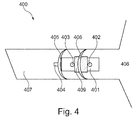
- the acoustical module 401 comprises two acoustical pressure pick-up points 402, 403 for receiving incoming sound from the outer ear 408.
- the acoustical module is positioned in the ear channel 407 with a sound generating receiver 404 facing the eardrum (not shown).
- a pair or dome shaped acoustical filters 405, 406 improve the wearing comfort of the acoustical module while being positioned in the ear channel 407.
- the dome 406 forms an acoustical filter between acoustical pressure pick-up points 402, 403 so that acoustical sound arriving from the outer ear 408 is attenuated before arriving at pressure pick-up point 403.
- the acoustical pressure pick-up points 402, 403 may optionally be used as one or more venting holes for the sound generating receiver 404. Alternatively or in combination therewith one or more dedicated venting holes (not shown) may be provided.
- a dedicated venting hole is to be understood as a venting hole not serving any other purpose than being a venting hole for the receiver.
- the dome 406 is attached to or integrated with the sleeve 409 which is dimensioned to match the outer dimension of the acoustical module 401.
- the sleeve 409 makes it easier to mount the dome 406 to the acoustical module 401.
- the sleeve 409 is manufactured by a flexible/elastic material so that it may be kept in position relative to the acoustical module 401 by contractive forces.
- the dome 406 and the sleeve 409 are preferable made as an integrated component, i.e. a one-piece component.
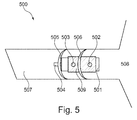
- the length of the sleeve 509 has been increased so that it now surrounds the two acoustical pressure pick-up points 502, 503 of the acoustical module 501.
- the acoustical module of Fig. 5 is positioned in an ear channel 507 with a sound generating receiver 504 facing the eardrum (not shown).
- a pair or dome shaped acoustical filters 505, 506 improve the wearing comfort of the acoustical module while being positioned in the ear channel 507.
- the dome 506 forms an acoustical filter between acoustical pressure pick-up points 502, 503 so that acoustical sound arriving from the outer ear 508 is attenuated before arriving at pressure pick-up point 503.
- the acoustical pressure pick-up points 502, 503 may optionally be used as one or more venting holes for the sound generating receiver 504. Alternatively or in combination therewith one or more dedicated venting holes (not shown) may be provided.
- a dedicated venting hole is to be understood as a venting hole not serving any other purpose than being a venting hole for the receiver.
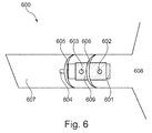
- protection grids have been arranged in front of the two acoustical pressure pick-up points 602, 603.
- the protection grids may be separate grids or they may form an integral part of the sleeve 609.
- the embodiment 600 of Fig. 6 is similar to that of Fig. 5 thus comprising an acoustical module 601 having domes 605, 606 attached thereto - the latter via the sleeve 609.
- a sound generating receiver 604 faces the eardrum of the ear channel 607 which terminates at the outer ear 608.
- the acoustical pressure pick-up points 602, 603 may optionally be used as one or more venting holes for the sound generating receiver 604.
- one or more dedicated venting holes may be provided.
- a dedicated venting hole is to be understood as a venting hole not serving any other purpose than being a venting hole for the receiver.
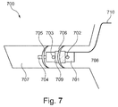
- the embodiment 700 shown in Fig. 7 has an integrated sports lock 710. Otherwise it us similar to the embodiment shown in Fig. 4 thus comprising an acoustical module 701 comprises two acoustical pressure pick-up points 702, 703 for receiving incoming sound from the outer ear 708.
- the acoustical module is positioned in the ear channel 707 with a sound generating receiver 704 facing the eardrum (not shown).
- the two dome shaped acoustical filters 705, 706 improve the wearing comfort while being positioned in the ear channel 707.
- the dome 706 forms an acoustical filter between acoustical pressure pick-up point 702 and 703.
- the acoustical pressure pick-up points 702 and 703 may optionally be used as one or more venting holes for the sound generating receiver 704.
- one or more dedicated venting holes may be provided.
- a dedicated venting hole is to be understood as a venting hole not serving any other purpose than being a venting hole for the receiver.
- dome 706/sleeve 709 is disclosed in detail in relation to the embodiment shown in Fig. 4 .
- the domes 105, 206, 405, 505, 605 and 705 have been disclosed as acoustical filters. However, this may necessary not be the case in that these domes have the primary purpose of supporting the acoustical module.
Landscapes
- Health & Medical Sciences (AREA)
- General Health & Medical Sciences (AREA)
- Neurosurgery (AREA)
- Otolaryngology (AREA)
- Physics & Mathematics (AREA)
- Engineering & Computer Science (AREA)
- Acoustics & Sound (AREA)
- Signal Processing (AREA)
- Circuit For Audible Band Transducer (AREA)
- Headphones And Earphones (AREA)
Applications Claiming Priority (1)
| Application Number | Priority Date | Filing Date | Title |
|---|---|---|---|
| EP15185813 | 2015-09-18 |
Publications (2)
| Publication Number | Publication Date |
|---|---|
| EP3148218A1 true EP3148218A1 (de) | 2017-03-29 |
| EP3148218B1 EP3148218B1 (de) | 2019-12-18 |
Family
ID=54150310
Family Applications (1)
| Application Number | Title | Priority Date | Filing Date |
|---|---|---|---|
| EP16189013.2A Active EP3148218B1 (de) | 2015-09-18 | 2016-09-15 | Akustisches modul mit akustischem filter |
Country Status (2)
| Country | Link |
|---|---|
| EP (1) | EP3148218B1 (de) |
| DK (1) | DK3148218T3 (de) |
Cited By (1)
| Publication number | Priority date | Publication date | Assignee | Title |
|---|---|---|---|---|
| CN115943642A (zh) * | 2020-08-26 | 2023-04-07 | 声扬荷兰有限公司 | 布置在接收器单元喷嘴顶部的传声器单元 |
Citations (6)
| Publication number | Priority date | Publication date | Assignee | Title |
|---|---|---|---|---|
| GB1383473A (en) * | 1972-02-02 | 1974-02-12 | Bommer Ag | Hearing aid |
| WO2001001732A1 (en) * | 1999-06-24 | 2001-01-04 | Tøpholm & Westermann APS | Hearing aid with controllable directional characteristics |
| US20010008559A1 (en) * | 2000-01-19 | 2001-07-19 | Roo Dion Ivo De | Directional microphone assembly |
| US6724902B1 (en) * | 1999-04-29 | 2004-04-20 | Insound Medical, Inc. | Canal hearing device with tubular insert |
| US8259976B2 (en) | 2008-04-02 | 2012-09-04 | Sonion Nederland B.V. | Assembly comprising a sound emitter and two sound detectors |
| EP2843971A1 (de) * | 2013-09-02 | 2015-03-04 | Oticon A/s | Hörgerät mit Mikrofon im Gehörkanal |
-
2016
- 2016-09-15 EP EP16189013.2A patent/EP3148218B1/de active Active
- 2016-09-15 DK DK16189013.2T patent/DK3148218T3/da active
Patent Citations (6)
| Publication number | Priority date | Publication date | Assignee | Title |
|---|---|---|---|---|
| GB1383473A (en) * | 1972-02-02 | 1974-02-12 | Bommer Ag | Hearing aid |
| US6724902B1 (en) * | 1999-04-29 | 2004-04-20 | Insound Medical, Inc. | Canal hearing device with tubular insert |
| WO2001001732A1 (en) * | 1999-06-24 | 2001-01-04 | Tøpholm & Westermann APS | Hearing aid with controllable directional characteristics |
| US20010008559A1 (en) * | 2000-01-19 | 2001-07-19 | Roo Dion Ivo De | Directional microphone assembly |
| US8259976B2 (en) | 2008-04-02 | 2012-09-04 | Sonion Nederland B.V. | Assembly comprising a sound emitter and two sound detectors |
| EP2843971A1 (de) * | 2013-09-02 | 2015-03-04 | Oticon A/s | Hörgerät mit Mikrofon im Gehörkanal |
Cited By (1)
| Publication number | Priority date | Publication date | Assignee | Title |
|---|---|---|---|---|
| CN115943642A (zh) * | 2020-08-26 | 2023-04-07 | 声扬荷兰有限公司 | 布置在接收器单元喷嘴顶部的传声器单元 |
Also Published As
| Publication number | Publication date |
|---|---|
| EP3148218B1 (de) | 2019-12-18 |
| DK3148218T3 (da) | 2020-02-24 |
Similar Documents
| Publication | Publication Date | Title |
|---|---|---|
| EP3403417B1 (de) | Kopfhörer mit kombinierter ohrmuschel und ohrstöpsel | |
| US10327071B2 (en) | Head-wearable hearing device | |
| AU2004203048B2 (en) | Active Noise Suppression for a Hearing Aid Device Which Can Be Worn in the Ear or a Hearing Aid Device With Otoplasty Which Can Be Worn in the Ear | |
| CN101091412B (zh) | 用于声音增强的装置和方法 | |
| US9247337B2 (en) | Headphone and headset | |
| US20050157895A1 (en) | Hearing aid having acoustical feedback protection | |
| US9060232B2 (en) | Hearing aid device with a directional microphone system and method for operating a hearing aid device having a directional microphone system | |
| KR20200143707A (ko) | 오디오 향상 청력 보호 시스템 | |
| EP2830324B1 (de) | Kopfhörer und Headset | |
| US10057697B2 (en) | Hearing device with a barrier element | |
| US20200213689A1 (en) | Microphone assembly | |
| US9538298B2 (en) | Attenuating tip for hearing aid | |
| WO2009071896A1 (en) | Apparatus for accurate ambient noise sensing and reduction in the presence of wind | |
| US12089001B2 (en) | Hearing device | |
| CN113015052A (zh) | 低频噪声降低的可穿戴电子设备 | |
| US9565501B2 (en) | Hearing device and method of identifying hearing situations having different signal sources | |
| EP3148218B1 (de) | Akustisches modul mit akustischem filter | |
| US9668065B2 (en) | Acoustical module with acoustical filter | |
| CN103069845B (zh) | 麦克风保护装置、麦克风单元及助听器 | |
| EP1730993B1 (de) | Höreinrichtung mit zwei oder mehr mikrofonen | |
| US20170085996A1 (en) | Acoustical module with acoustical filter | |
| US20250324194A1 (en) | Vibration insulation suspension for ear wearable audio components | |
| JP6965203B2 (ja) | 聴覚機器のための閉塞制御システムおよび聴覚機器 | |
| US8477974B2 (en) | Hearing device and method for producing an omnidirectional directional characteristic | |
| US20260082162A1 (en) | Method of operating a hearing device and hearing device |
Legal Events
| Date | Code | Title | Description |
|---|---|---|---|
| PUAI | Public reference made under article 153(3) epc to a published international application that has entered the european phase |
Free format text: ORIGINAL CODE: 0009012 |
|
| STAA | Information on the status of an ep patent application or granted ep patent |
Free format text: STATUS: THE APPLICATION HAS BEEN PUBLISHED |
|
| AK | Designated contracting states |
Kind code of ref document: A1 Designated state(s): AL AT BE BG CH CY CZ DE DK EE ES FI FR GB GR HR HU IE IS IT LI LT LU LV MC MK MT NL NO PL PT RO RS SE SI SK SM TR |
|
| AX | Request for extension of the european patent |
Extension state: BA ME |
|
| STAA | Information on the status of an ep patent application or granted ep patent |
Free format text: STATUS: REQUEST FOR EXAMINATION WAS MADE |
|
| STAA | Information on the status of an ep patent application or granted ep patent |
Free format text: STATUS: EXAMINATION IS IN PROGRESS |
|
| 17P | Request for examination filed |
Effective date: 20170407 |
|
| RBV | Designated contracting states (corrected) |
Designated state(s): AL AT BE BG CH CY CZ DE DK EE ES FI FR GB GR HR HU IE IS IT LI LT LU LV MC MK MT NL NO PL PT RO RS SE SI SK SM TR |
|
| 17Q | First examination report despatched |
Effective date: 20170516 |
|
| GRAP | Despatch of communication of intention to grant a patent |
Free format text: ORIGINAL CODE: EPIDOSNIGR1 |
|
| STAA | Information on the status of an ep patent application or granted ep patent |
Free format text: STATUS: GRANT OF PATENT IS INTENDED |
|
| INTG | Intention to grant announced |
Effective date: 20190702 |
|
| GRAS | Grant fee paid |
Free format text: ORIGINAL CODE: EPIDOSNIGR3 |
|
| GRAA | (expected) grant |
Free format text: ORIGINAL CODE: 0009210 |
|
| STAA | Information on the status of an ep patent application or granted ep patent |
Free format text: STATUS: THE PATENT HAS BEEN GRANTED |
|
| AK | Designated contracting states |
Kind code of ref document: B1 Designated state(s): AL AT BE BG CH CY CZ DE DK EE ES FI FR GB GR HR HU IE IS IT LI LT LU LV MC MK MT NL NO PL PT RO RS SE SI SK SM TR |
|
| REG | Reference to a national code |
Ref country code: CH Ref legal event code: EP |
|
| REG | Reference to a national code |
Ref country code: IE Ref legal event code: FG4D |
|
| REG | Reference to a national code |
Ref country code: DE Ref legal event code: R096 Ref document number: 602016026294 Country of ref document: DE |
|
| REG | Reference to a national code |
Ref country code: AT Ref legal event code: REF Ref document number: 1215921 Country of ref document: AT Kind code of ref document: T Effective date: 20200115 |
|
| REG | Reference to a national code |
Ref country code: DK Ref legal event code: T3 Effective date: 20200217 |
|
| REG | Reference to a national code |
Ref country code: NL Ref legal event code: MP Effective date: 20191218 |
|
| PG25 | Lapsed in a contracting state [announced via postgrant information from national office to epo] |
Ref country code: FI Free format text: LAPSE BECAUSE OF FAILURE TO SUBMIT A TRANSLATION OF THE DESCRIPTION OR TO PAY THE FEE WITHIN THE PRESCRIBED TIME-LIMIT Effective date: 20191218 Ref country code: BG Free format text: LAPSE BECAUSE OF FAILURE TO SUBMIT A TRANSLATION OF THE DESCRIPTION OR TO PAY THE FEE WITHIN THE PRESCRIBED TIME-LIMIT Effective date: 20200318 Ref country code: GR Free format text: LAPSE BECAUSE OF FAILURE TO SUBMIT A TRANSLATION OF THE DESCRIPTION OR TO PAY THE FEE WITHIN THE PRESCRIBED TIME-LIMIT Effective date: 20200319 Ref country code: NO Free format text: LAPSE BECAUSE OF FAILURE TO SUBMIT A TRANSLATION OF THE DESCRIPTION OR TO PAY THE FEE WITHIN THE PRESCRIBED TIME-LIMIT Effective date: 20200318 Ref country code: LT Free format text: LAPSE BECAUSE OF FAILURE TO SUBMIT A TRANSLATION OF THE DESCRIPTION OR TO PAY THE FEE WITHIN THE PRESCRIBED TIME-LIMIT Effective date: 20191218 Ref country code: LV Free format text: LAPSE BECAUSE OF FAILURE TO SUBMIT A TRANSLATION OF THE DESCRIPTION OR TO PAY THE FEE WITHIN THE PRESCRIBED TIME-LIMIT Effective date: 20191218 Ref country code: SE Free format text: LAPSE BECAUSE OF FAILURE TO SUBMIT A TRANSLATION OF THE DESCRIPTION OR TO PAY THE FEE WITHIN THE PRESCRIBED TIME-LIMIT Effective date: 20191218 |
|
| REG | Reference to a national code |
Ref country code: LT Ref legal event code: MG4D |
|
| PG25 | Lapsed in a contracting state [announced via postgrant information from national office to epo] |
Ref country code: RS Free format text: LAPSE BECAUSE OF FAILURE TO SUBMIT A TRANSLATION OF THE DESCRIPTION OR TO PAY THE FEE WITHIN THE PRESCRIBED TIME-LIMIT Effective date: 20191218 Ref country code: HR Free format text: LAPSE BECAUSE OF FAILURE TO SUBMIT A TRANSLATION OF THE DESCRIPTION OR TO PAY THE FEE WITHIN THE PRESCRIBED TIME-LIMIT Effective date: 20191218 |
|
| PG25 | Lapsed in a contracting state [announced via postgrant information from national office to epo] |
Ref country code: AL Free format text: LAPSE BECAUSE OF FAILURE TO SUBMIT A TRANSLATION OF THE DESCRIPTION OR TO PAY THE FEE WITHIN THE PRESCRIBED TIME-LIMIT Effective date: 20191218 |
|
| PG25 | Lapsed in a contracting state [announced via postgrant information from national office to epo] |
Ref country code: RO Free format text: LAPSE BECAUSE OF FAILURE TO SUBMIT A TRANSLATION OF THE DESCRIPTION OR TO PAY THE FEE WITHIN THE PRESCRIBED TIME-LIMIT Effective date: 20191218 Ref country code: EE Free format text: LAPSE BECAUSE OF FAILURE TO SUBMIT A TRANSLATION OF THE DESCRIPTION OR TO PAY THE FEE WITHIN THE PRESCRIBED TIME-LIMIT Effective date: 20191218 Ref country code: PT Free format text: LAPSE BECAUSE OF FAILURE TO SUBMIT A TRANSLATION OF THE DESCRIPTION OR TO PAY THE FEE WITHIN THE PRESCRIBED TIME-LIMIT Effective date: 20200513 Ref country code: CZ Free format text: LAPSE BECAUSE OF FAILURE TO SUBMIT A TRANSLATION OF THE DESCRIPTION OR TO PAY THE FEE WITHIN THE PRESCRIBED TIME-LIMIT Effective date: 20191218 Ref country code: NL Free format text: LAPSE BECAUSE OF FAILURE TO SUBMIT A TRANSLATION OF THE DESCRIPTION OR TO PAY THE FEE WITHIN THE PRESCRIBED TIME-LIMIT Effective date: 20191218 |
|
| PG25 | Lapsed in a contracting state [announced via postgrant information from national office to epo] |
Ref country code: IS Free format text: LAPSE BECAUSE OF FAILURE TO SUBMIT A TRANSLATION OF THE DESCRIPTION OR TO PAY THE FEE WITHIN THE PRESCRIBED TIME-LIMIT Effective date: 20200418 Ref country code: SK Free format text: LAPSE BECAUSE OF FAILURE TO SUBMIT A TRANSLATION OF THE DESCRIPTION OR TO PAY THE FEE WITHIN THE PRESCRIBED TIME-LIMIT Effective date: 20191218 Ref country code: SM Free format text: LAPSE BECAUSE OF FAILURE TO SUBMIT A TRANSLATION OF THE DESCRIPTION OR TO PAY THE FEE WITHIN THE PRESCRIBED TIME-LIMIT Effective date: 20191218 |
|
| REG | Reference to a national code |
Ref country code: DE Ref legal event code: R097 Ref document number: 602016026294 Country of ref document: DE |
|
| REG | Reference to a national code |
Ref country code: AT Ref legal event code: MK05 Ref document number: 1215921 Country of ref document: AT Kind code of ref document: T Effective date: 20191218 |
|
| PLBE | No opposition filed within time limit |
Free format text: ORIGINAL CODE: 0009261 |
|
| STAA | Information on the status of an ep patent application or granted ep patent |
Free format text: STATUS: NO OPPOSITION FILED WITHIN TIME LIMIT |
|
| PG25 | Lapsed in a contracting state [announced via postgrant information from national office to epo] |
Ref country code: ES Free format text: LAPSE BECAUSE OF FAILURE TO SUBMIT A TRANSLATION OF THE DESCRIPTION OR TO PAY THE FEE WITHIN THE PRESCRIBED TIME-LIMIT Effective date: 20191218 |
|
| 26N | No opposition filed |
Effective date: 20200921 |
|
| PG25 | Lapsed in a contracting state [announced via postgrant information from national office to epo] |
Ref country code: SI Free format text: LAPSE BECAUSE OF FAILURE TO SUBMIT A TRANSLATION OF THE DESCRIPTION OR TO PAY THE FEE WITHIN THE PRESCRIBED TIME-LIMIT Effective date: 20191218 Ref country code: AT Free format text: LAPSE BECAUSE OF FAILURE TO SUBMIT A TRANSLATION OF THE DESCRIPTION OR TO PAY THE FEE WITHIN THE PRESCRIBED TIME-LIMIT Effective date: 20191218 |
|
| PG25 | Lapsed in a contracting state [announced via postgrant information from national office to epo] |
Ref country code: IT Free format text: LAPSE BECAUSE OF FAILURE TO SUBMIT A TRANSLATION OF THE DESCRIPTION OR TO PAY THE FEE WITHIN THE PRESCRIBED TIME-LIMIT Effective date: 20191218 |
|
| PG25 | Lapsed in a contracting state [announced via postgrant information from national office to epo] |
Ref country code: PL Free format text: LAPSE BECAUSE OF FAILURE TO SUBMIT A TRANSLATION OF THE DESCRIPTION OR TO PAY THE FEE WITHIN THE PRESCRIBED TIME-LIMIT Effective date: 20191218 |
|
| PG25 | Lapsed in a contracting state [announced via postgrant information from national office to epo] |
Ref country code: MC Free format text: LAPSE BECAUSE OF FAILURE TO SUBMIT A TRANSLATION OF THE DESCRIPTION OR TO PAY THE FEE WITHIN THE PRESCRIBED TIME-LIMIT Effective date: 20191218 |
|
| REG | Reference to a national code |
Ref country code: BE Ref legal event code: MM Effective date: 20200930 |
|
| PG25 | Lapsed in a contracting state [announced via postgrant information from national office to epo] |
Ref country code: LU Free format text: LAPSE BECAUSE OF NON-PAYMENT OF DUE FEES Effective date: 20200915 |
|
| PG25 | Lapsed in a contracting state [announced via postgrant information from national office to epo] |
Ref country code: BE Free format text: LAPSE BECAUSE OF NON-PAYMENT OF DUE FEES Effective date: 20200930 Ref country code: IE Free format text: LAPSE BECAUSE OF NON-PAYMENT OF DUE FEES Effective date: 20200915 |
|
| PG25 | Lapsed in a contracting state [announced via postgrant information from national office to epo] |
Ref country code: TR Free format text: LAPSE BECAUSE OF FAILURE TO SUBMIT A TRANSLATION OF THE DESCRIPTION OR TO PAY THE FEE WITHIN THE PRESCRIBED TIME-LIMIT Effective date: 20191218 Ref country code: MT Free format text: LAPSE BECAUSE OF FAILURE TO SUBMIT A TRANSLATION OF THE DESCRIPTION OR TO PAY THE FEE WITHIN THE PRESCRIBED TIME-LIMIT Effective date: 20191218 Ref country code: CY Free format text: LAPSE BECAUSE OF FAILURE TO SUBMIT A TRANSLATION OF THE DESCRIPTION OR TO PAY THE FEE WITHIN THE PRESCRIBED TIME-LIMIT Effective date: 20191218 |
|
| PG25 | Lapsed in a contracting state [announced via postgrant information from national office to epo] |
Ref country code: MK Free format text: LAPSE BECAUSE OF FAILURE TO SUBMIT A TRANSLATION OF THE DESCRIPTION OR TO PAY THE FEE WITHIN THE PRESCRIBED TIME-LIMIT Effective date: 20191218 |
|
| PGFP | Annual fee paid to national office [announced via postgrant information from national office to epo] |
Ref country code: DK Payment date: 20240913 Year of fee payment: 9 |
|
| PGFP | Annual fee paid to national office [announced via postgrant information from national office to epo] |
Ref country code: GB Payment date: 20240808 Year of fee payment: 9 |
|
| PGFP | Annual fee paid to national office [announced via postgrant information from national office to epo] |
Ref country code: FR Payment date: 20240821 Year of fee payment: 9 |
|
| PGFP | Annual fee paid to national office [announced via postgrant information from national office to epo] |
Ref country code: CH Payment date: 20241001 Year of fee payment: 9 |
|
| PGFP | Annual fee paid to national office [announced via postgrant information from national office to epo] |
Ref country code: DE Payment date: 20250919 Year of fee payment: 10 |
|
| REG | Reference to a national code |
Ref country code: DK Ref legal event code: EBP Effective date: 20250930 |