EP3148241B1 - Kapazitätserweiterungsverfahren und vorrichtung für drahtloses netzwerk - Google Patents
Kapazitätserweiterungsverfahren und vorrichtung für drahtloses netzwerk Download PDFInfo
- Publication number
- EP3148241B1 EP3148241B1 EP14892639.7A EP14892639A EP3148241B1 EP 3148241 B1 EP3148241 B1 EP 3148241B1 EP 14892639 A EP14892639 A EP 14892639A EP 3148241 B1 EP3148241 B1 EP 3148241B1
- Authority
- EP
- European Patent Office
- Prior art keywords
- grids
- base station
- grid
- network
- deployed
- Prior art date
- Legal status (The legal status is an assumption and is not a legal conclusion. Google has not performed a legal analysis and makes no representation as to the accuracy of the status listed.)
- Active
Links
Images



Classifications
-
- H—ELECTRICITY
- H04—ELECTRIC COMMUNICATION TECHNIQUE
- H04W—WIRELESS COMMUNICATION NETWORKS
- H04W16/00—Network planning, e.g. coverage or traffic planning tools; Network deployment, e.g. resource partitioning or cells structures
- H04W16/22—Traffic simulation tools or models
-
- H—ELECTRICITY
- H04—ELECTRIC COMMUNICATION TECHNIQUE
- H04W—WIRELESS COMMUNICATION NETWORKS
- H04W16/00—Network planning, e.g. coverage or traffic planning tools; Network deployment, e.g. resource partitioning or cells structures
- H04W16/18—Network planning tools
-
- H—ELECTRICITY
- H04—ELECTRIC COMMUNICATION TECHNIQUE
- H04W—WIRELESS COMMUNICATION NETWORKS
- H04W16/00—Network planning, e.g. coverage or traffic planning tools; Network deployment, e.g. resource partitioning or cells structures
- H04W16/24—Cell structures
- H04W16/32—Hierarchical cell structures
Definitions
- the present invention pertains to the field of wireless communications technologies, and specifically relates to a wireless network capacity expansion method and device.
- a most effective network capacity expansion means is to add and deploy a micro cellular base station or a pico cellular base station (hereinafter referred to as a micro base station) based on an existing macro cellular base station (hereinafter referred to as a macro base station), so as to improve a network capacity by means of better spectrum reuse.
- One important problem during networking of a heterogeneous network is how to deploy and configure a plurality of micro base stations based on an existing macro cellular network to construct a heterogeneous network including a plurality of macro base stations and micro base stations.
- a macro base station is added to the macro cellular network by means of a drive test.
- this method is not applicable to deployment of micro base stations, because a quantity of newly-added micro base stations is much greater than that of macro base stations.
- the drive test method is time-consuming and effort-consuming.
- grid division is performed on a target region, and a grid in which a micro base station is deployed is determined aiming at a minimum average path loss from grids to micro base station covering the grids.
- a device identifies mobile devices within a geographical area associated with a carrier network.
- the device further divides the geographical area into cells.
- the device also collects network statistics associated with the mobile devices.
- the device assigns values to the cells based on the network statistics, and identifies locations in which to place the small cells within the geographical area based on the values.
- the present invention provides a wireless network capacity expansion method and device, so as to overcome a disadvantage in the prior art that it is difficult to ensure a network capacity after a micro base station is added.
- grid division is performed on a target region covered by a macro cellular network, to obtain a plurality of grids, and N first grids are determined among the plurality of grids based on a network gain, where the N first grids need to meet a condition: deploying one micro base station in each of the first grids brings a maximum network gain corresponding to the target region.
- a position of a grid in which a micro base station is deployed is determined based on the network gain, which optimizes a network capacity to a greatest extent when one micro base station is deployed in each grid of the determined N first grids.
- FIG. 1 is a flowchart of a wireless network capacity expansion method according to Embodiment 1 of the present invention.
- the method provided in this embodiment is particularly applicable to any scenario in which a network capacity is expanded by adding and deploying a micro base station on a wireless communications network, and is particularly applicable to a mobile cellular network.
- Different types of micro base stations may be deployed in different wireless networks.
- a micro base station deployed in the mobile cellular network may be a small cell or an access point.
- the method may be executed by a network side device.
- the device is on a management platform of an operator, or in an operation and maintenance center (Operation and Maintenance Center, OMC for short).
- OMC Opera and Maintenance Center
- grid division is first performed on the target region covered by the macro cellular network, to obtain the plurality of grids.
- the target region covered by the macro cellular network includes a plurality of macro base stations, and each macro base station covers an area, that is, each macro base station covers a plurality of grids.
- At least one group of N first grids needs to be determined among the plurality of grids obtained by means of gridding, for example, M (M is an integer greater than or equal to 1) groups of N first grids. That is, there are totally M groups, and each group includes N first grids.
- M is an integer greater than or equal to 1
- each group includes N first grids.
- Deploying one micro base station in each grid of the M ⁇ N first grids brings a maximum network capacity of the target region. That is, each group of N first grids in this embodiment needs to meet a condition: deploying one micro base station in each first grid brings the maximum network gain corresponding to the target region.
- the network gain may include a network capacity gain and a network coverage gain.
- the network capacity gain represents an optimization degree of the network capacity of the target region
- the network coverage gain represents an optimization degree of network coverage of the target region, that is, a degree to which coverage vulnerability is caused by interference caused by a newly-added micro base station to a user.
- a greater network coverage gain indicates a lower degree to which coverage vulnerability is caused by the interference caused by the newly-added micro base station to the user.
- the network gain is maximum means that the network capacity gain is maximum while a requirement for the network coverage gain is met.
- the N first grids meeting the foregoing condition are determined among the plurality of grids obtained by gridding the target region.
- the N first grids may be determined in the following manner. It is assumed that A grids are obtained by means of gridding, N grids are randomly selected from the A grids each time, and the network gain: the network capacity gain and the network coverage gain, that are brought about if one micro base station is deployed in each of the N randomly selected grids is determined by analogy, until all possibilities of random selection are tried; then, the network gains corresponding to all random selections are compared, N grids corresponding to a random selection with a greatest network gain is determined, and one micro base station is deployed in each of the N grids.
- the foregoing process is repeated for multiple times, so as to finally determine a plurality of groups of N first grids, and micro base stations are deployed in the plurality of groups of N first grids, so as to implement network capacity expansion.
- Optional implementation manners are described in the following other embodiments.
- grid division is performed on a target region covered by a macro cellular network, to obtain a plurality of grids, and based on a network gain including a network capacity gain and a network coverage gain, N first grids are determined among the plurality of grids, where the N first grids need to meet a condition: deploying one micro base station in each of the first grids brings a maximum network gain corresponding to the target region.
- a position of a grid in which a micro base station is deployed is determined based on the network gain, which optimizes a network capacity when a coverage requirement is met.
- FIG. 2 is a flowchart of a wireless network capacity expansion method according to Embodiment 2 of the present invention. As shown in FIG. 2 , the method includes: Step 201: Perform grid division on a target region covered by a macro cellular network, to obtain a plurality of grids.
- N first grids need to be determined among the plurality of grids, which may be specifically implemented by using the following process:
- Step 203 Determine that grids that enable the network capacity gain to be greater than 0 and the network coverage gain to be greater than 0 constitute the L second grids.
- N first grids are determined among the L second grids includes:
- the following condition needs to be met: it is assumed that micro base stations are deployed in any two second grids in the L second grids, interference between the any two grids is less than a preset interference threshold. A distance between grids that meets the condition is defined as the interference distance threshold, and the interference distance threshold is used as a parameter for subsequently selecting and determining the N first grids.
- a process of determining at least one group of N first grids among the L second grids is a multi-iteration process, and each iteration results in one group of N first grids.
- a preset iteration termination condition is met, iteration ends, at least one group of N first grids is finally obtained, and one micro base station is deployed in each of the at least one group of N first grids.
- the iteration termination condition includes: a quantity of iterations reaches a preset quantity of times, or a difference between network gains corresponding to two adjacent groups of N first grids that are obtained by means of iteration is less than a preset difference.
- One traverse specifically includes the following steps:
- the L second grids are first sorted randomly; then, the L second grids are traversed, and the N third grids are selected from the L second grids, where a distance between any two third grids is greater than the interference distance threshold; and whether deploying one micro base station in each of the third grids brings the maximum network gain corresponding to the target region is determined, and if deploying one micro base station in each of the third grids brings the maximum network gain corresponding to the target region, the N third grids are determined as the N first grids.
- L second grids that can be used as candidate grids for deploying micro base stations are determined among a plurality of grids obtained from an original gridded target region, and then, at least one group of N first grids is determined among the L second grids and is used as final grids for deploying the micro base stations, thereby not only further reducing calculation amount, but also ensuring an accurate determining result, which facilitates optimization of a network capacity and network coverage.
- parameters of a newly-added micro base station and an existing macro base station may be adjusted, and a specific adjustment process is as follows:
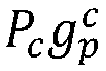
- each grid of the plurality of grids obtained after the target region is gridded is used as a to-be-processed grid. It is assumed that before a micro base station is deployed, a to-be-processed grid i is associated with a macro base station c, that is, the to-be-processed grid i is covered by the macro base station c , and it can be determined that first reference signal strength RS i of the macro base station c in the to-be-processed grid i is determined by P c g i c .
- the to-be-processed grid i may be no longer associated with the macro base station c, and may be associated with a micro base station c', that is, the to-be-processed grid i is covered by the micro base station c'.
- second reference signal strength RS i of the micro base station c' in the to-be-processed grid i is determined by P c ′ g i c ′ .
- the second reference signal strength is greater than the first reference signal strength, it is considered that the micro base station c' that the to-be-processed grid i is associated with is a to-be-adjusted base station, and a parameter of the to-be-adjusted base station c' needs to be adjusted.
- the second reference signal strength is generally compared with a product of the first reference signal strength and a sensitivity coefficient.
- a to-be-adjusted parameter includes a transmit power and/or an antenna downtilt.
- the transmit power of the to-be-adjusted base station is adjusted according to a first preset step; or the antenna downtilt of the to-be-adjusted base station is adjusted according to a second preset step.
- the foregoing adjustment process is performed time by time, that is, each adjustment is performed according to the preset steps, and after each adjustment, whether a network capacity gain of the target region after each adjustment is greater than 0 needs to be determined, next adjustment is performed if the network capacity gain is greater than 0, and so on, and adjusting the to-be-adjusted base station ends when the network capacity gain is not greater than 0.
- a transmit power range is configured for each to-be-adjusted base station, and adjustment is performed time by time by using the first preset step as a unit within the range.
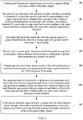
- FIG. 3 is a flowchart of a multi-iteration process in Embodiment 2 shown in FIG. 2 , and as shown in FIG. 3 :
- an iteration termination condition may also be that a network gain difference between two groups of N first grids of two adjacent iteration results is less than a preset threshold.
- Step 315 Obtain at least one group of N first grids.
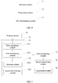
- FIG. 4 is a schematic structural diagram of a wireless network capacity expansion device according to Embodiment 3 of the present invention. As shown in FIG. 4 , the device includes:
- the device in this embodiment may be configured to execute a technical solution of the method embodiment shown in FIG. 1 , and implementation principles and technical effects thereof are similar, and details are not described herein again.
- FIG. 5 is a schematic structural diagram of a wireless network capacity expansion device according to Embodiment 4 of the present invention. As shown in FIG. 5 , the device in this embodiment is based on the embodiment shown in FIG. 4 , and the processing module 12 includes:
- the first processing unit 121 includes: a first calculation subunit 1211, configured to: successively for each grid of the plurality of grids, calculate, according to formula (1), a network capacity gain that is corresponding to the target region and that is obtained after one micro base station is deployed independently in each grid, and calculate, according to formula (2), a network coverage gain that is corresponding to the target region and that is obtained after one micro base station is deployed in each grid:
- U 1 p Capacity S ⁇ p ⁇ Capacity S
- U 2 p Coverage S ⁇ p ⁇ Coverage S
- U 1 ( p ) is the network capacity gain that is corresponding to the target region and that is obtained after one micro base station is deployed in any grid p in the plurality of grids
- U 2 ( p ) is the network coverage gain that is corresponding to the target region and that is obtained after one micro base station is deployed in any grid p in the plurality of grids
- S is a set of macro base stations included in the target region
- the second processing unit 122 specifically includes:
- the selection subunit 1221 is specifically configured to:
- the device further includes:
- the adjustment module 22 is specifically configured to: adjust a transmit power of the to-be-adjusted base station according to a first preset step; or adjust an antenna downtilt of the to-be-adjusted base station according to a second preset step.
- the device in this embodiment may be configured to execute technical solutions of the method embodiments shown in FIG. 2 and FIG. 3 , and implementation principles and technical effects thereof are similar, and details are not described herein again.
- FIG. 6 is a schematic structural diagram of a network device according to Embodiment 5 of the present invention.
- the network device includes: a memory 31 and a processor 32 connected to the memory 31, where the memory 31 is configured to store a set of program code, and the processor 32 is configured to invoke the program code stored in the memory 31 to execute steps in the wireless network capacity expansion method shown in FIG.
- the processor 32 is further configured to: determine L second grids among the plurality of grids, where deploying one micro base station in each of the second grids increases a network gain corresponding to the target region, and L is an integer greater than N; and determine the N first grids among the L second grids.
- the processor 32 is further configured to: successively for each grid of the plurality of grids, calculate, according to formula (1), a network capacity gain that is corresponding to the target region and that is obtained after one micro base station is deployed independently in each grid, and calculate, according to formula (2), a network coverage gain that is corresponding to the target region and that is obtained after one micro base station is deployed in each grid:
- U 1 p Capacity S ⁇ p ⁇ Capacity S
- U 2 p Coverage S ⁇ p ⁇ Coverage S
- U 1 ( p ) is the network capacity gain that is corresponding to the target region and that is obtained after one micro base station is deployed in any grid p in the plurality of grids
- U 2 ( p ) is the network coverage gain that is corresponding to the target region and that is obtained after one micro base station is deployed in any grid p in the plurality of grids
- S is a set of macro base stations included in the target region
- Capacity ( S ) is a network capacity that is of
- the processor 32 is further configured to traverse the L second grids, and determine N third grids among the L second grids, where a distance between any two third grids is greater than an interference distance threshold; and determine the N third grids as the N first grids if deploying one micro base station in each of the third grids brings the maximum network gain corresponding to the target region.
- the processor 32 is further configured to: by using each grid of the plurality of grids as a to-be-processed grid, determine first reference signal strength that is of the to-be-processed grid and that is obtained before one micro base station is deployed in each of the first grids, and second reference signal strength that is of the to-be-processed grid and that is obtained after one micro base station is deployed in each of the first grids; and if the second reference signal strength is greater than the first reference signal strength, determine a base station corresponding to the to-be-processed grid as a to-be-adjusted base station, and adjust a parameter of the to-be-adjusted base station.
- the processor 32 is further configured to adjust a transmit power of the to-be-adjusted base station according to a first preset step; or adjust an antenna downtilt of the to-be-adjusted base station according to a second preset step.
- the previous program may be stored in a computer readable storage medium. When the program is run, the steps of the foregoing method embodiments are performed.
- the previous storage medium includes various mediums that are capable of storing the program code, such as a ROM, a RAM, a magnetic disk, or an optical disc.
Landscapes
- Engineering & Computer Science (AREA)
- Computer Networks & Wireless Communication (AREA)
- Signal Processing (AREA)
- Mobile Radio Communication Systems (AREA)
Claims (9)
- Drahtlosnetzkapazitätserweiterungsverfahren, das Folgendes umfasst:Durchführen einer Rasterunterteilung an einem Zielgebiet, das durch ein zellulares Makronetz abgedeckt wird, um mehrere Raster zu erhalten;Bestimmen von N ersten Rastern unter den mehreren Rastern, wobei das Einsetzen einer Mikrobasisstation in jedem der ersten Raster eine maximale Netzverstärkung, die dem Zielgebiet entspricht, erzielt und N eine ganze Zahl größer als 1 ist; undBestimmen, dass eine Mikrobasisstation in jedem der N ersten Raster eingesetzt wird; dadurch gekennzeichnet, dass das Bestimmen der N ersten Raster unter den mehreren Rastern Folgendes umfasst:Bestimmen von L zweiten Rastern unter den mehreren Rastern, wobei das Einsetzen einer Mikrobasisstation in jedem der zweiten Raster eine Netzverstärkung, die dem Zielgebiet entspricht, erhöht und L eine ganze Zahl größer als N ist; undBestimmen der N ersten Raster unter den L zweiten Rastern;wobei das Bestimmen der L zweiten Raster unter den mehreren Rastern Folgendes umfasst:
sukzessive für jedes Raster der mehreren Raster, Berechnen, gemäß Formel (1), eines Netzkapazitätszuwachses, der dem Zielgebiet entspricht und der erhalten wird, nachdem eine Basisstation unabhängig in jedem Raster eingesetzt wurde, und Berechnen, gemäß Formel (2), eines Netzabdeckungszuwachses, der dem Zielgebiet entspricht und der erhalten wird, nachdem eine Mikrobasisstation in jedem Raster eingesetzt wurde:





- Verfahren nach Anspruch 1, wobei das Bestimmen der N ersten Raster unter den L zweiten Rastern Folgendes umfasst:Durchlaufen der L zweiten Raster und Bestimmen von N dritten Rastern unter den L zweiten Rastern, so dass eine Entfernung zwischen zwei beliebigen dritten Rastern größer als eine Störungsentfernungsschwelle ist; undBestimmen der N dritten Raster als die N ersten Raster, falls das Einsetzen einer Mikrobasisstation in jedem der dritten Raster die maximale Netzverstärkung erzielt, die dem Zielgebiet entspricht.
- Verfahren nach Anspruch 2, wobei das Bestimmen der Störungsentfernungsschwelle wie folgt ist:Bestimmen einer Störung zwischen zwei beliebigen der L zweiten Raster gemäß Formel (6):
 Bestimmen einer Entfernung zwischen Rastern, die ermöglicht, dass die Störung geringer als eine voreingestellte Störungsschwelle ist, als die Störungsentfernungsschwelle.
 - Verfahren nach einem der Ansprüche 1 bis 3, das nach dem Bestimmen, dass eine Mikrobasisstation in jedem der N ersten Raster eingesetzt wird, ferner Folgendes umfasst:durch Verwenden jedes Rasters der mehreren Raster als ein zu verarbeitendes Raster, Bestimmen einer ersten Referenzsignalstärke, die von dem zu verarbeitenden Raster stammt und die erhalten wird, bevor eine Mikrobasisstation in jedem der ersten Raster eingesetzt wird, und einer zweiten Referenzsignalstärke, die von dem zu verarbeitenden Raster stammt und die erhalten wird, nachdem eine Mikrobasisstation in jedem der ersten Raster eingesetzt wurde; undfalls die zweite Referenzsignalstärke größer als die erste Referenzsignalstärke ist, Bestimmen der Basisstation, die in dem zu verarbeitenden Raster eingesetzt wird, als eine anzupassende Basisstation und Anpassen eines Parameters der anzupassenden Basisstation;wobei das Anpassen eines Parameters der anzupassenden Basisstation Folgendes umfasst:Anpassen einer Sendeleistung der anzupassenden Basisstation gemäß einem ersten voreingestellten Schritt; und/oderAnpassen einer Antennenabwärtsneigung der anzupassenden Basisstation gemäß einem zweiten voreingestellten Schritt.
- Drahtlosnetzkapazitätserweiterungsvorrichtung, die Folgendes umfasst:ein Unterteilungsmodul, das zum Durchführen einer Rasterunterteilung an einem Zielgebiet konfiguriert ist, das durch ein zellulares Makronetz abgedeckt wird, um mehrere Raster zu erhalten;ein Verarbeitungsmodul, das zum Bestimmen von N ersten Rastern unter den mehreren Rastern konfiguriert ist, wobei das Einsetzen einer Mikrobasisstation in jedem der ersten Raster eine maximale Netzverstärkung, die dem Zielgebiet entspricht, erzielt und N eine ganze Zahl größer als 1 ist; undein erstes Bestimmungsmodul, das zum Bestimmen gemäß den N ersten Rastern, die durch das Verarbeitungsmodul bestimmt werden, konfiguriert ist, dass eine Mikrobasisstation in jedem der N ersten Raster eingesetzt wird;dadurch gekennzeichnet, dass das Verarbeitungsmodul Folgendes umfasst:eine erste Verarbeitungseinheit, die zum Bestimmen von L zweiten Rastern unter den mehreren Rastern konfiguriert ist, wobei das Einsetzen einer Mikrobasisstation in jedem der zweiten Raster eine Netzverstärkung, die dem Zielgebiet entspricht, erhöht und L eine ganze Zahl größer als N ist; undeine zweite Verarbeitungseinheit, die zum Bestimmen der N ersten Raster unter den L zweiten Rastern konfiguriert ist;wobei die erste Verarbeitungseinheit Folgendes umfasst:
eine erste Berechnungsuntereinheit, die zu Folgendem konfiguriert ist: sukzessive für jedes Raster der mehreren Raster, Berechnen, gemäß Formel (1), eines Netzkapazitätszuwachses, der dem Zielgebiet entspricht und der erhalten wird, nachdem eine Mikrobasisstation unabhängig in jedem Raster eingesetzt wurde, und Berechnen, gemäß Formel (2), eines Netzabdeckungszuwachses, der dem Zielgebiet entspricht und der erhalten wird, nachdem eine Mikrobasisstation in jedem Raster eingesetzt wurde:




eine erste Bestimmungsuntereinheit, die zum Bestimmen konfiguriert ist, dass Raster, die ermöglichen, dass der Netzkapazitätszuwachs größer als 0 ist und der Netzabdeckungszuwachs größer als 0 ist, die L zweiten Raster darstellen. - Vorrichtung nach Anspruch 5, wobei die zweite Verarbeitungseinheit Folgendes umfasst:eine Auswahluntereinheit, die zum Durchlaufen der L zweiten Raster und zum Bestimmen von N dritten Rastern unter den L zweiten Rastern konfiguriert ist, so dass eine Entfernung zwischen zwei beliebigen dritten Rastern größer als eine Störungsentfernungsschwelle ist; undeine zweite Bestimmungsuntereinheit die zum Bestimmen der N dritten Raster als die N ersten Raster konfiguriert ist, falls das Einsetzen einer Mikrobasisstation in jedem der dritten Raster die maximale Netzverstärkung erzielt, die dem Zielgebiet entspricht.
- Vorrichtung nach Anspruch 6, wobei die Auswahluntereinheit ferner zu Folgendem konfiguriert ist:Bestimmen einer Störung zwischen zwei beliebigen zweiten Rastern der L zweiten Raster gemäß Formel (6):
 Bestimmen einer Entfernung zwischen Rastern, die ermöglicht, dass die Störung geringer als eine voreingestellte Störungsschwelle ist, als die Störungsentfernungsschwelle.
 - Vorrichtung nach einem der Ansprüche 5 bis 7, die ferner Folgendes umfasst:ein zweites Bestimmungsmodul, das zu Folgendem konfiguriert ist: durch Verwenden jedes Rasters der mehreren Raster als ein zu verarbeitendes Raster, Bestimmen einer ersten Referenzsignalstärke, die von dem zu verarbeitenden Raster stammt und die erhalten wird, bevor eine Mikrobasisstation in jedem der ersten Raster eingesetzt wird, und einer zweiten Referenzsignalstärke, die von dem zu verarbeitenden Raster stammt und die erhalten wird, nachdem eine Mikrobasisstation in jedem der ersten Raster eingesetzt wurde; undein Anpassungsmodul, das zu Folgendem konfiguriert ist: falls die zweite Referenzsignalstärke größer als die erste Referenzsignalstärke ist, Bestimmen der Basisstation, die in dem zu verarbeitenden Raster eingesetzt wird, als eine anzupassende Basisstation und Anpassen eines Parameters der anzupassenden Basisstation;wobei das Anpassungsmodul speziell zu Folgendem konfiguriert ist:
Anpassen einer Sendeleistung der anzupassenden Basisstation gemäß einem ersten voreingestellten Schritt; oder Anpassen einer Antennenabwärtsneigung der anzupassenden Basisstation gemäß einem zweiten voreingestellten Schritt. - Netzvorrichtung, die Folgendes umfasst:
einen Speicher und einen Prozessor, der mit dem Speicher verbunden ist, wobei der Speicher zum Speichern eines Satzes von Programmcode konfiguriert ist und der Prozessor zum Aufrufen des in dem Speicher gespeicherten Programmcodes konfiguriert ist, um das Verfahren nach einem der Ansprüche 1 bis 4 auszuführen.
Applications Claiming Priority (1)
| Application Number | Priority Date | Filing Date | Title |
|---|---|---|---|
| PCT/CN2014/078034 WO2015176258A1 (zh) | 2014-05-21 | 2014-05-21 | 无线网络扩容方法和设备 |
Publications (3)
| Publication Number | Publication Date |
|---|---|
| EP3148241A1 EP3148241A1 (de) | 2017-03-29 |
| EP3148241A4 EP3148241A4 (de) | 2017-05-17 |
| EP3148241B1 true EP3148241B1 (de) | 2020-03-25 |
Family
ID=54553213
Family Applications (1)
| Application Number | Title | Priority Date | Filing Date |
|---|---|---|---|
| EP14892639.7A Active EP3148241B1 (de) | 2014-05-21 | 2014-05-21 | Kapazitätserweiterungsverfahren und vorrichtung für drahtloses netzwerk |
Country Status (3)
| Country | Link |
|---|---|
| EP (1) | EP3148241B1 (de) |
| CN (1) | CN106465142B (de) |
| WO (1) | WO2015176258A1 (de) |
Families Citing this family (12)
| Publication number | Priority date | Publication date | Assignee | Title |
|---|---|---|---|---|
| CN108260075B (zh) * | 2016-12-27 | 2020-10-02 | 中国移动通信集团浙江有限公司 | 一种基站部署位置的寻址方法及装置 |
| CN107347188B (zh) * | 2017-06-19 | 2020-09-11 | 国网浙江省电力公司嘉兴供电公司 | 一种基于td-lte230网络的电网基站初步选址方法 |
| CN107682862B (zh) * | 2017-07-13 | 2020-12-25 | 国网浙江省电力公司嘉兴供电公司 | 一种td-lte230电力系统通信网络基站的选址方法 |
| CN109327841B (zh) * | 2018-09-30 | 2020-11-17 | 湖南华诺科技有限公司 | 基于覆盖、价值关联的多维评定及精准建设评估方法 |
| CN109661001B (zh) * | 2019-01-11 | 2022-06-07 | 中国联合网络通信集团有限公司 | 一种网络优化方法和服务器 |
| CN111225408B (zh) * | 2019-12-31 | 2024-01-26 | 京信网络系统股份有限公司 | 基于SmallCell基站的无线环境监控方法、装置、设备和存储介质 |
| CN113965270B (zh) * | 2020-07-20 | 2023-08-22 | 华为技术有限公司 | 一种emf强度控制方法及通信装置 |
| GB2603604B (en) * | 2020-11-30 | 2023-04-05 | Jio Platforms Ltd | System and method for automated planning of next generation telecom network |
| CN114448813B (zh) * | 2021-12-28 | 2024-03-22 | 天津市邮电设计院有限责任公司 | 一种网络扩容比例的确定方法、装置、服务器及介质 |
| CN114501477B (zh) * | 2022-02-23 | 2024-04-02 | 阿里巴巴(中国)有限公司 | 无线基站的安装点确定方法、装置及终端设备 |
| CN116546606A (zh) * | 2023-05-17 | 2023-08-04 | 长春理工大学 | 一种基于Dyna-Q的超密集异构网络功率控制算法 |
| CN116614826B (zh) * | 2023-05-24 | 2024-01-16 | 北京天坦智能科技有限责任公司 | 一种同时传输和反射表面网络的覆盖和容量优化方法 |
Family Cites Families (6)
| Publication number | Priority date | Publication date | Assignee | Title |
|---|---|---|---|---|
| CN101494871B (zh) * | 2008-01-24 | 2011-02-23 | 中兴通讯股份有限公司 | 微小区建设的规划方法 |
| CN102547752B (zh) * | 2010-12-07 | 2015-08-19 | 中国移动通信集团广东有限公司 | 一种无线网络的覆盖评估方法及装置 |
| US8437765B2 (en) * | 2011-08-11 | 2013-05-07 | Verizon Patent And Licensing Inc. | Identifying locations for small cells |
| CN103118369B (zh) * | 2011-11-16 | 2016-04-06 | 华为技术有限公司 | 站址的选择方法和设备以及栅格选择方法和设备 |
| CN103476041B (zh) * | 2013-08-30 | 2016-08-10 | 浙江大学 | 一种蜂窝移动通信网络多小区联合覆盖优化方法和装置 |
| CN103702337B (zh) * | 2014-01-03 | 2017-04-19 | 北京邮电大学 | 一种小型基站部署位置的确定方法 |
-
2014
- 2014-05-21 CN CN201480078952.3A patent/CN106465142B/zh active Active
- 2014-05-21 WO PCT/CN2014/078034 patent/WO2015176258A1/zh not_active Ceased
- 2014-05-21 EP EP14892639.7A patent/EP3148241B1/de active Active
Non-Patent Citations (1)
| Title |
|---|
| None * |
Also Published As
| Publication number | Publication date |
|---|---|
| CN106465142A (zh) | 2017-02-22 |
| CN106465142B (zh) | 2019-11-19 |
| EP3148241A1 (de) | 2017-03-29 |
| EP3148241A4 (de) | 2017-05-17 |
| WO2015176258A1 (zh) | 2015-11-26 |
Similar Documents
| Publication | Publication Date | Title |
|---|---|---|
| EP3148241A1 (de) | Kapazitätserweiterungsverfahren und vorrichtung für drahtloses netzwerk | |
| US10425860B2 (en) | System and method for value optimized mobile networks | |
| US10149312B2 (en) | Resource scheduling method and apparatus | |
| WO2017050113A1 (en) | System and method for a multi view learning approach to anomaly detection and root cause analysis | |
| EP3360360B1 (de) | System und verfahren für lastneuausgleich | |
| US20230063522A1 (en) | Optimizing a cellular network using a machine learning model | |
| EP3669566B1 (de) | Gemeinschaftsdetektion in funkzugangsnetzwerken mit einschränkungen | |
| US9924372B2 (en) | Method for sharing of unlicensed radio frequency bands by cellular LTE and WiFi networks | |
| JP2011188164A (ja) | 基地局装置および通信帯域割り当て方法 | |
| Madapatha et al. | Constrained deployment optimization in integrated access and backhaul networks | |
| EP4260532A1 (de) | Lastverwaltung von überlappenden zellen auf der basis des benutzerdurchsatzes | |
| Ghosh et al. | Coverage and rate analysis in two‐tier heterogeneous networks under suburban and urban scenarios | |
| US20240098566A1 (en) | Load management of overlapping cells based on user throughput | |
| CN111385039B (zh) | 一种小区广播波束参数的调整方法及装置 | |
| JP2023509544A (ja) | 電子機器、無線通信方法及びコンピュータ読み取り可能な記憶媒体 | |
| US10165449B2 (en) | Method of planning of mobile telecommunications networks | |
| US10257714B2 (en) | Channel selection algorithm with consecutive search loops | |
| Arikawa et al. | High-speed radio-resource scheduling for 5G ultra-high-density distributed antenna systems | |
| US11234186B2 (en) | Scheduling apparatus and method, and program | |
| WO2022159081A1 (en) | Load management of overlapping cells based on user throughput | |
| KR102593994B1 (ko) | 위치 기반 핑거프린트를 이용한 최적빔 선택 시스템 및 방법 | |
| EP3202176B1 (de) | Differenzierte anpassung von auswahlwahrscheinlichkeiten für frequenzkanalauswahl | |
| KR101682290B1 (ko) | 다중셀 랜덤엑세스 네트워크에서 간섭정렬 및 제어를 위한 프레임 전송 시스템 및 방법 | |
| de Oliveira Torres et al. | Interference mitigation in next generation networks using clustering and intelligence techniques | |
| Mubarok et al. | Planning of LTE-Apro Network using Licensed Assisted Access combining Spectrum Licensed 1800MHz and Unlicensed 5GHz |
Legal Events
| Date | Code | Title | Description |
|---|---|---|---|
| STAA | Information on the status of an ep patent application or granted ep patent |
Free format text: STATUS: THE INTERNATIONAL PUBLICATION HAS BEEN MADE |
|
| PUAI | Public reference made under article 153(3) epc to a published international application that has entered the european phase |
Free format text: ORIGINAL CODE: 0009012 |
|
| STAA | Information on the status of an ep patent application or granted ep patent |
Free format text: STATUS: REQUEST FOR EXAMINATION WAS MADE |
|
| 17P | Request for examination filed |
Effective date: 20161117 |
|
| AK | Designated contracting states |
Kind code of ref document: A1 Designated state(s): AL AT BE BG CH CY CZ DE DK EE ES FI FR GB GR HR HU IE IS IT LI LT LU LV MC MK MT NL NO PL PT RO RS SE SI SK SM TR |
|
| AX | Request for extension of the european patent |
Extension state: BA ME |
|
| A4 | Supplementary search report drawn up and despatched |
Effective date: 20170421 |
|
| RIC1 | Information provided on ipc code assigned before grant |
Ipc: H04W 16/32 20090101ALI20170413BHEP Ipc: H04W 16/22 20090101ALI20170413BHEP Ipc: H04W 16/18 20090101AFI20170413BHEP |
|
| DAX | Request for extension of the european patent (deleted) | ||
| RIN1 | Information on inventor provided before grant (corrected) |
Inventor name: YI, YOUWEN Inventor name: ZHUANG, HONGCHENG Inventor name: SHMELKIN, DMITRI |
|
| REG | Reference to a national code |
Ref country code: DE Ref legal event code: R079 Ref document number: 602014062994 Country of ref document: DE Free format text: PREVIOUS MAIN CLASS: H04W0016180000 Ipc: H04W0016220000 |
|
| GRAP | Despatch of communication of intention to grant a patent |
Free format text: ORIGINAL CODE: EPIDOSNIGR1 |
|
| STAA | Information on the status of an ep patent application or granted ep patent |
Free format text: STATUS: GRANT OF PATENT IS INTENDED |
|
| RIC1 | Information provided on ipc code assigned before grant |
Ipc: H04W 16/22 20090101AFI20191015BHEP Ipc: H04W 16/18 20090101ALI20191015BHEP Ipc: H04W 16/32 20090101ALI20191015BHEP |
|
| INTG | Intention to grant announced |
Effective date: 20191108 |
|
| GRAS | Grant fee paid |
Free format text: ORIGINAL CODE: EPIDOSNIGR3 |
|
| GRAA | (expected) grant |
Free format text: ORIGINAL CODE: 0009210 |
|
| STAA | Information on the status of an ep patent application or granted ep patent |
Free format text: STATUS: THE PATENT HAS BEEN GRANTED |
|
| AK | Designated contracting states |
Kind code of ref document: B1 Designated state(s): AL AT BE BG CH CY CZ DE DK EE ES FI FR GB GR HR HU IE IS IT LI LT LU LV MC MK MT NL NO PL PT RO RS SE SI SK SM TR |
|
| REG | Reference to a national code |
Ref country code: GB Ref legal event code: FG4D |
|
| REG | Reference to a national code |
Ref country code: AT Ref legal event code: REF Ref document number: 1250012 Country of ref document: AT Kind code of ref document: T Effective date: 20200415 Ref country code: IE Ref legal event code: FG4D |
|
| REG | Reference to a national code |
Ref country code: DE Ref legal event code: R096 Ref document number: 602014062994 Country of ref document: DE |
|
| PG25 | Lapsed in a contracting state [announced via postgrant information from national office to epo] |
Ref country code: RS Free format text: LAPSE BECAUSE OF FAILURE TO SUBMIT A TRANSLATION OF THE DESCRIPTION OR TO PAY THE FEE WITHIN THE PRESCRIBED TIME-LIMIT Effective date: 20200325 Ref country code: NO Free format text: LAPSE BECAUSE OF FAILURE TO SUBMIT A TRANSLATION OF THE DESCRIPTION OR TO PAY THE FEE WITHIN THE PRESCRIBED TIME-LIMIT Effective date: 20200625 Ref country code: FI Free format text: LAPSE BECAUSE OF FAILURE TO SUBMIT A TRANSLATION OF THE DESCRIPTION OR TO PAY THE FEE WITHIN THE PRESCRIBED TIME-LIMIT Effective date: 20200325 |
|
| PG25 | Lapsed in a contracting state [announced via postgrant information from national office to epo] |
Ref country code: LV Free format text: LAPSE BECAUSE OF FAILURE TO SUBMIT A TRANSLATION OF THE DESCRIPTION OR TO PAY THE FEE WITHIN THE PRESCRIBED TIME-LIMIT Effective date: 20200325 Ref country code: SE Free format text: LAPSE BECAUSE OF FAILURE TO SUBMIT A TRANSLATION OF THE DESCRIPTION OR TO PAY THE FEE WITHIN THE PRESCRIBED TIME-LIMIT Effective date: 20200325 Ref country code: HR Free format text: LAPSE BECAUSE OF FAILURE TO SUBMIT A TRANSLATION OF THE DESCRIPTION OR TO PAY THE FEE WITHIN THE PRESCRIBED TIME-LIMIT Effective date: 20200325 Ref country code: BG Free format text: LAPSE BECAUSE OF FAILURE TO SUBMIT A TRANSLATION OF THE DESCRIPTION OR TO PAY THE FEE WITHIN THE PRESCRIBED TIME-LIMIT Effective date: 20200625 Ref country code: GR Free format text: LAPSE BECAUSE OF FAILURE TO SUBMIT A TRANSLATION OF THE DESCRIPTION OR TO PAY THE FEE WITHIN THE PRESCRIBED TIME-LIMIT Effective date: 20200626 |
|
| REG | Reference to a national code |
Ref country code: NL Ref legal event code: MP Effective date: 20200325 |
|
| REG | Reference to a national code |
Ref country code: LT Ref legal event code: MG4D |
|
| PG25 | Lapsed in a contracting state [announced via postgrant information from national office to epo] |
Ref country code: NL Free format text: LAPSE BECAUSE OF FAILURE TO SUBMIT A TRANSLATION OF THE DESCRIPTION OR TO PAY THE FEE WITHIN THE PRESCRIBED TIME-LIMIT Effective date: 20200325 |
|
| PG25 | Lapsed in a contracting state [announced via postgrant information from national office to epo] |
Ref country code: SK Free format text: LAPSE BECAUSE OF FAILURE TO SUBMIT A TRANSLATION OF THE DESCRIPTION OR TO PAY THE FEE WITHIN THE PRESCRIBED TIME-LIMIT Effective date: 20200325 Ref country code: RO Free format text: LAPSE BECAUSE OF FAILURE TO SUBMIT A TRANSLATION OF THE DESCRIPTION OR TO PAY THE FEE WITHIN THE PRESCRIBED TIME-LIMIT Effective date: 20200325 Ref country code: CZ Free format text: LAPSE BECAUSE OF FAILURE TO SUBMIT A TRANSLATION OF THE DESCRIPTION OR TO PAY THE FEE WITHIN THE PRESCRIBED TIME-LIMIT Effective date: 20200325 Ref country code: LT Free format text: LAPSE BECAUSE OF FAILURE TO SUBMIT A TRANSLATION OF THE DESCRIPTION OR TO PAY THE FEE WITHIN THE PRESCRIBED TIME-LIMIT Effective date: 20200325 Ref country code: IS Free format text: LAPSE BECAUSE OF FAILURE TO SUBMIT A TRANSLATION OF THE DESCRIPTION OR TO PAY THE FEE WITHIN THE PRESCRIBED TIME-LIMIT Effective date: 20200725 Ref country code: PT Free format text: LAPSE BECAUSE OF FAILURE TO SUBMIT A TRANSLATION OF THE DESCRIPTION OR TO PAY THE FEE WITHIN THE PRESCRIBED TIME-LIMIT Effective date: 20200818 Ref country code: EE Free format text: LAPSE BECAUSE OF FAILURE TO SUBMIT A TRANSLATION OF THE DESCRIPTION OR TO PAY THE FEE WITHIN THE PRESCRIBED TIME-LIMIT Effective date: 20200325 Ref country code: SM Free format text: LAPSE BECAUSE OF FAILURE TO SUBMIT A TRANSLATION OF THE DESCRIPTION OR TO PAY THE FEE WITHIN THE PRESCRIBED TIME-LIMIT Effective date: 20200325 |
|
| REG | Reference to a national code |
Ref country code: AT Ref legal event code: MK05 Ref document number: 1250012 Country of ref document: AT Kind code of ref document: T Effective date: 20200325 |
|
| REG | Reference to a national code |
Ref country code: DE Ref legal event code: R097 Ref document number: 602014062994 Country of ref document: DE |
|
| PG25 | Lapsed in a contracting state [announced via postgrant information from national office to epo] |
Ref country code: LI Free format text: LAPSE BECAUSE OF NON-PAYMENT OF DUE FEES Effective date: 20200531 Ref country code: AT Free format text: LAPSE BECAUSE OF FAILURE TO SUBMIT A TRANSLATION OF THE DESCRIPTION OR TO PAY THE FEE WITHIN THE PRESCRIBED TIME-LIMIT Effective date: 20200325 Ref country code: ES Free format text: LAPSE BECAUSE OF FAILURE TO SUBMIT A TRANSLATION OF THE DESCRIPTION OR TO PAY THE FEE WITHIN THE PRESCRIBED TIME-LIMIT Effective date: 20200325 Ref country code: CH Free format text: LAPSE BECAUSE OF NON-PAYMENT OF DUE FEES Effective date: 20200531 Ref country code: DK Free format text: LAPSE BECAUSE OF FAILURE TO SUBMIT A TRANSLATION OF THE DESCRIPTION OR TO PAY THE FEE WITHIN THE PRESCRIBED TIME-LIMIT Effective date: 20200325 Ref country code: MC Free format text: LAPSE BECAUSE OF FAILURE TO SUBMIT A TRANSLATION OF THE DESCRIPTION OR TO PAY THE FEE WITHIN THE PRESCRIBED TIME-LIMIT Effective date: 20200325 Ref country code: IT Free format text: LAPSE BECAUSE OF FAILURE TO SUBMIT A TRANSLATION OF THE DESCRIPTION OR TO PAY THE FEE WITHIN THE PRESCRIBED TIME-LIMIT Effective date: 20200325 |
|
| PLBE | No opposition filed within time limit |
Free format text: ORIGINAL CODE: 0009261 |
|
| STAA | Information on the status of an ep patent application or granted ep patent |
Free format text: STATUS: NO OPPOSITION FILED WITHIN TIME LIMIT |
|
| PG25 | Lapsed in a contracting state [announced via postgrant information from national office to epo] |
Ref country code: PL Free format text: LAPSE BECAUSE OF FAILURE TO SUBMIT A TRANSLATION OF THE DESCRIPTION OR TO PAY THE FEE WITHIN THE PRESCRIBED TIME-LIMIT Effective date: 20200325 |
|
| 26N | No opposition filed |
Effective date: 20210112 |
|
| REG | Reference to a national code |
Ref country code: BE Ref legal event code: MM Effective date: 20200531 |
|
| GBPC | Gb: european patent ceased through non-payment of renewal fee |
Effective date: 20200625 |
|
| PG25 | Lapsed in a contracting state [announced via postgrant information from national office to epo] |
Ref country code: LU Free format text: LAPSE BECAUSE OF NON-PAYMENT OF DUE FEES Effective date: 20200521 |
|
| PG25 | Lapsed in a contracting state [announced via postgrant information from national office to epo] |
Ref country code: IE Free format text: LAPSE BECAUSE OF NON-PAYMENT OF DUE FEES Effective date: 20200521 Ref country code: GB Free format text: LAPSE BECAUSE OF NON-PAYMENT OF DUE FEES Effective date: 20200625 |
|
| PG25 | Lapsed in a contracting state [announced via postgrant information from national office to epo] |
Ref country code: BE Free format text: LAPSE BECAUSE OF NON-PAYMENT OF DUE FEES Effective date: 20200531 Ref country code: SI Free format text: LAPSE BECAUSE OF FAILURE TO SUBMIT A TRANSLATION OF THE DESCRIPTION OR TO PAY THE FEE WITHIN THE PRESCRIBED TIME-LIMIT Effective date: 20200325 |
|
| PG25 | Lapsed in a contracting state [announced via postgrant information from national office to epo] |
Ref country code: TR Free format text: LAPSE BECAUSE OF FAILURE TO SUBMIT A TRANSLATION OF THE DESCRIPTION OR TO PAY THE FEE WITHIN THE PRESCRIBED TIME-LIMIT Effective date: 20200325 Ref country code: MT Free format text: LAPSE BECAUSE OF FAILURE TO SUBMIT A TRANSLATION OF THE DESCRIPTION OR TO PAY THE FEE WITHIN THE PRESCRIBED TIME-LIMIT Effective date: 20200325 Ref country code: CY Free format text: LAPSE BECAUSE OF FAILURE TO SUBMIT A TRANSLATION OF THE DESCRIPTION OR TO PAY THE FEE WITHIN THE PRESCRIBED TIME-LIMIT Effective date: 20200325 |
|
| PG25 | Lapsed in a contracting state [announced via postgrant information from national office to epo] |
Ref country code: MK Free format text: LAPSE BECAUSE OF FAILURE TO SUBMIT A TRANSLATION OF THE DESCRIPTION OR TO PAY THE FEE WITHIN THE PRESCRIBED TIME-LIMIT Effective date: 20200325 Ref country code: AL Free format text: LAPSE BECAUSE OF FAILURE TO SUBMIT A TRANSLATION OF THE DESCRIPTION OR TO PAY THE FEE WITHIN THE PRESCRIBED TIME-LIMIT Effective date: 20200325 |
|
| REG | Reference to a national code |
Ref country code: FR Ref legal event code: PLFP Year of fee payment: 10 |
|
| PGFP | Annual fee paid to national office [announced via postgrant information from national office to epo] |
Ref country code: DE Payment date: 20250402 Year of fee payment: 12 |
|
| PGFP | Annual fee paid to national office [announced via postgrant information from national office to epo] |
Ref country code: FR Payment date: 20250401 Year of fee payment: 12 |