EP3148280A1 - Procédé et dispositif de communication - Google Patents
Procédé et dispositif de communication Download PDFInfo
- Publication number
- EP3148280A1 EP3148280A1 EP14895407.6A EP14895407A EP3148280A1 EP 3148280 A1 EP3148280 A1 EP 3148280A1 EP 14895407 A EP14895407 A EP 14895407A EP 3148280 A1 EP3148280 A1 EP 3148280A1
- Authority
- EP
- European Patent Office
- Prior art keywords
- communication path
- transmitter
- transmitters
- target
- uplink
- Prior art date
- Legal status (The legal status is an assumption and is not a legal conclusion. Google has not performed a legal analysis and makes no representation as to the accuracy of the status listed.)
- Withdrawn
Links
- 238000004891 communication Methods 0.000 title claims abstract description 811
- 238000000034 method Methods 0.000 title claims abstract description 41
- 230000005540 biological transmission Effects 0.000 claims abstract description 62
- 238000004364 calculation method Methods 0.000 claims description 23
- 238000003780 insertion Methods 0.000 claims description 20
- 230000037431 insertion Effects 0.000 claims description 20
- 238000001774 stimulated Raman spectroscopy Methods 0.000 claims description 16
- 238000001514 detection method Methods 0.000 claims description 7
- 238000010586 diagram Methods 0.000 description 46
- 238000013468 resource allocation Methods 0.000 description 14
- 238000001228 spectrum Methods 0.000 description 12
- 230000010267 cellular communication Effects 0.000 description 7
- 238000005516 engineering process Methods 0.000 description 5
- 238000004422 calculation algorithm Methods 0.000 description 2
- 230000003993 interaction Effects 0.000 description 2
- 230000001960 triggered effect Effects 0.000 description 2
- 230000009286 beneficial effect Effects 0.000 description 1
- 230000001413 cellular effect Effects 0.000 description 1
- 238000004590 computer program Methods 0.000 description 1
- 230000003287 optical effect Effects 0.000 description 1
- 230000035515 penetration Effects 0.000 description 1
Images


Classifications
-
- H—ELECTRICITY
- H04—ELECTRIC COMMUNICATION TECHNIQUE
- H04W—WIRELESS COMMUNICATION NETWORKS
- H04W76/00—Connection management
- H04W76/10—Connection setup
- H04W76/15—Setup of multiple wireless link connections
-
- H—ELECTRICITY
- H04—ELECTRIC COMMUNICATION TECHNIQUE
- H04W—WIRELESS COMMUNICATION NETWORKS
- H04W24/00—Supervisory, monitoring or testing arrangements
- H04W24/02—Arrangements for optimising operational condition
-
- H—ELECTRICITY
- H04—ELECTRIC COMMUNICATION TECHNIQUE
- H04B—TRANSMISSION
- H04B7/00—Radio transmission systems, i.e. using radiation field
- H04B7/02—Diversity systems; Multi-antenna system, i.e. transmission or reception using multiple antennas
- H04B7/04—Diversity systems; Multi-antenna system, i.e. transmission or reception using multiple antennas using two or more spaced independent antennas
- H04B7/06—Diversity systems; Multi-antenna system, i.e. transmission or reception using multiple antennas using two or more spaced independent antennas at the transmitting station
- H04B7/0613—Diversity systems; Multi-antenna system, i.e. transmission or reception using multiple antennas using two or more spaced independent antennas at the transmitting station using simultaneous transmission
- H04B7/0615—Diversity systems; Multi-antenna system, i.e. transmission or reception using multiple antennas using two or more spaced independent antennas at the transmitting station using simultaneous transmission of weighted versions of same signal
- H04B7/0617—Diversity systems; Multi-antenna system, i.e. transmission or reception using multiple antennas using two or more spaced independent antennas at the transmitting station using simultaneous transmission of weighted versions of same signal for beam forming
-
- H—ELECTRICITY
- H04—ELECTRIC COMMUNICATION TECHNIQUE
- H04L—TRANSMISSION OF DIGITAL INFORMATION, e.g. TELEGRAPHIC COMMUNICATION
- H04L5/00—Arrangements affording multiple use of the transmission path
- H04L5/003—Arrangements for allocating sub-channels of the transmission path
- H04L5/0048—Allocation of pilot signals, i.e. of signals known to the receiver
-
- H—ELECTRICITY
- H04—ELECTRIC COMMUNICATION TECHNIQUE
- H04W—WIRELESS COMMUNICATION NETWORKS
- H04W16/00—Network planning, e.g. coverage or traffic planning tools; Network deployment, e.g. resource partitioning or cells structures
- H04W16/24—Cell structures
- H04W16/28—Cell structures using beam steering
-
- H—ELECTRICITY
- H04—ELECTRIC COMMUNICATION TECHNIQUE
- H04W—WIRELESS COMMUNICATION NETWORKS
- H04W24/00—Supervisory, monitoring or testing arrangements
- H04W24/08—Testing, supervising or monitoring using real traffic
-
- H—ELECTRICITY
- H04—ELECTRIC COMMUNICATION TECHNIQUE
- H04W—WIRELESS COMMUNICATION NETWORKS
- H04W72/00—Local resource management
- H04W72/04—Wireless resource allocation
- H04W72/044—Wireless resource allocation based on the type of the allocated resource
- H04W72/0446—Resources in time domain, e.g. slots or frames
-
- H—ELECTRICITY
- H04—ELECTRIC COMMUNICATION TECHNIQUE
- H04W—WIRELESS COMMUNICATION NETWORKS
- H04W72/00—Local resource management
- H04W72/04—Wireless resource allocation
- H04W72/044—Wireless resource allocation based on the type of the allocated resource
- H04W72/0453—Resources in frequency domain, e.g. a carrier in FDMA
-
- H—ELECTRICITY
- H04—ELECTRIC COMMUNICATION TECHNIQUE
- H04W—WIRELESS COMMUNICATION NETWORKS
- H04W72/00—Local resource management
- H04W72/04—Wireless resource allocation
- H04W72/044—Wireless resource allocation based on the type of the allocated resource
- H04W72/046—Wireless resource allocation based on the type of the allocated resource the resource being in the space domain, e.g. beams
-
- H—ELECTRICITY
- H04—ELECTRIC COMMUNICATION TECHNIQUE
- H04W—WIRELESS COMMUNICATION NETWORKS
- H04W74/00—Wireless channel access
-
- H—ELECTRICITY
- H04—ELECTRIC COMMUNICATION TECHNIQUE
- H04W—WIRELESS COMMUNICATION NETWORKS
- H04W76/00—Connection management
-
- H—ELECTRICITY
- H04—ELECTRIC COMMUNICATION TECHNIQUE
- H04W—WIRELESS COMMUNICATION NETWORKS
- H04W76/00—Connection management
- H04W76/10—Connection setup
- H04W76/11—Allocation or use of connection identifiers
Definitions
- the present invention relates to the field of communications technologies, and in particular, to a communication method and a communications apparatus.
- a current wireless access manner is limited only to traditional cellular band access, where a communication frequency band of the current wireless access manner is below 2.6 GHz, communication is performed between a base station (English full name: Base Station, BS for short) and a mobile station (English full name: Mobile Station, MS for short), between BSs, and between MSs in a broadcast manner, and communication performed in the broadcast manner is characterized by a wide beam and a wide coverage area.
- a same sector may be considered as one beam, where MSs covered by the beam share bandwidths by occupying different frequencies, and more MSs covered by the beam indicate a less bandwidth occupied by each MS and a smaller capacity of each MS, which severely limits a size of service data transmitted by a user.
- Embodiments of the present invention provide a communication method and apparatus, which can effectively improve a system transmission capacity to some degree.
- an embodiment of the present invention provides a communications apparatus, including:
- the first determining module includes:
- the second determining module includes:
- the first path obtaining unit includes:
- the updating subunit is specifically configured to:
- the communications module includes:
- the communications module includes:
- the communications module includes:
- the communications module includes:
- the communications module includes:
- the communications apparatus further includes:
- an embodiment of the present invention further provides a communication method, including:
- the determining a primary communication path to a target transmitter according to a first SRS when the first SRS is received includes:
- the obtaining an identifier of a transmitter that performs communication by using the primary communication path, and determining a secondary communication path of a transmitter indicated by each identifier includes:
- the obtaining identifiers of transmitters that performs communication by using the primary communication path, and determining a secondary communication path of the target transmitter according to a second SRS that is sent by the target transmitter corresponding to a target identifier in the identifiers includes:
- the communication method further includes:
- the updating a communication path corresponding to the target direction to a secondary communication path includes:
- the communicating with the transmitter according to the primary communication path and the secondary communication path includes:
- the communicating with the transmitter according to the primary communication path and the secondary communication path includes:
- the communicating with the transmitter according to the primary communication path and the secondary communication path includes:
- the communicating with the transmitter according to the primary communication path and the secondary communication path includes:
- the communicating with the transmitter according to the primary communication path and the secondary communication path includes:
- the communication method further includes:
- an embodiment of the present invention further provides a computer storage medium, where the computer storage medium stores a program, and when the program runs, some or all of steps in the communication method in the foregoing second aspect are executed.
- an embodiment of the present invention further provides a communications device, including the communications apparatus in the foregoing first aspect.
- a primary communication path for communication between a current transmitter and a target transmitter may be determined according to an SRS signal received by a receiver, and a secondary communication path is determined for each transmitter that performs communication by using the primary communication path, so that communication with each transmitter is performed based on the primary communication path and the secondary communication path, which effectively improves a system transmission capacity.
- a receiver in the embodiments of the present invention may refer to a base station (English full name: Base Station, BS for short) or a mobile station (English full name: Mobile Station, MS for short), a transmitter may also be an MS or a BS, and communication in the embodiments of the present invention includes but is not limited to communication between BSs, between a BS and an MS, and between MSs.
- the MS includes user equipment (English full name: User Equipment, UE for short).
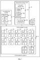
- FIG. 1 is a schematic structural diagram of a communications apparatus according to an embodiment of the present invention.
- the apparatus in this embodiment of the present invention may be specifically applied to a communications device that can be used as a receiver, for example, a base station.
- the apparatus may include a first determining module 10, a second determining module 20, and a communications module 30.
- the first determining module 10 is configured to determine a primary communication path to a target transmitter according to a first sounding reference signal SRS when the first SRS is received, where the target transmitter is a transmitter that sends the first SRS.
- the transmitter for example, UE
- the transmitter may be connected by using a wide beam to ensure normal communication.
- a process of connection by using the wide beam is the same as a process of connection by means of traditional wireless cellular communication, and details are not described herein.
- the first determining module 10 may be triggered to determine a primary communication path between the UE and a current receiver, that is, a BS.
- the primary communication path may refer to a communication path used during connection by means of the traditional wireless cellular communication, that is, a communication path with optimal channel quality.
- the primary communication path is a line of sight (English full name: Line of Sight, LoS for short) channel.
- LoS Line of Sight
- NLoS non-Line of Sight
- the method in this embodiment of the present invention may be implemented by using a millimeter-wave band as a communication frequency band.
- a millimeter wave refers to a high frequency band of 30 GHz to 300 GHz, and has relatively strong directivity and a more concentrated narrow beam. Therefore, performing communication by using a millimeter wave can obtain a higher antenna gain.
- a millimeter wave is characterized by concentrated beam energy, an energy loss on a reflection path or a diffraction path is relatively small. Therefore, the millimeter wave can be used for communication.
- the second determining module 20 is configured to: obtain an identifier of a transmitter that performs communication by using the primary communication path determined by the first determining module 10, and determine a secondary communication path of a transmitter indicated by each identifier.
- the BS that is, the current receiver, corresponding to the target UE may control a wide beam to be divided into narrow beams and users to be partitioned, and further search a respective area for a secondary communication path corresponding to the UE, so as to improve a user capacity and a system capacity.
- the secondary communication path may be an NLoS channel in a general case.
- the communications module 30 is configured to communicate with the transmitter according to the primary communication path determined by the first determining module 10 and the secondary communication path determined by the second determining module 20.
- the communications module 30 may communicate with the UE in the beam on the primary communication path according to the determined primary communication path and secondary communication path that are corresponding to the UE in the beam on the primary communication path.
- a primary communication path for communication between a current transmitter and a target transmitter may be determined according to an SRS signal received by a receiver, and a secondary communication path is determined for each transmitter that performs communication by using the primary communication path, so that communication with each transmitter is performed based on the primary communication path and the secondary communication path, which effectively improves a system transmission capacity.
- FIG. 2 is a schematic structural diagram of another communications apparatus according to an embodiment of the present invention.
- the apparatus in this embodiment of the present invention includes the first determining module 10, the second determining module 20, and the communications module 30 that are of the foregoing communications apparatus.
- the first determining module 10 may specifically include: a direction determining unit 101 and a beam narrowing unit 102.
- the direction determining unit 101 is configured to determine an optimal direction of arrival according to a preset determining rule if a first SRS is received.
- the first SRS is sent by a target transmitter, for example, newly connected UE, by using a fully deployed wide beam.
- the direction determining unit 101 may determine, according to the preset determining rule, the optimal direction of arrival from a direction in which the SRS signal is currently received, and feed back location information related to the optimal direction of arrival to the newly connected UE.
- the preset determining rule may be formed according to a particular algorithm and a particular criterion.
- the direction determining unit 101 may obtain, according to SRS signals in all directions, signal to interference plus noise ratio (English full name: Signal to Interference plus Noise Ratio, SINR for short) values corresponding to all the directions, and select a direction corresponding to a largest SINR value of the SINR values as the optimal direction of arrival.
- SINR Signal to Interference plus Noise Ratio
- the beam narrowing unit 102 is configured to: narrow, in the optimal direction of arrival determined by the direction determining unit 101, the wide beam used by the target transmitter, and determine, as a primary communication path, a communication path on which a narrowed beam is located.
- the beam narrowing unit 102 may narrow, in the optimal direction of arrival, the wide beam used by the UE.
- the beam narrowing unit 102 controls related beam control modules such as a precoding precoding adjustment module and a beamforming beamforming module to narrow the beam in the optimal direction of arrival.
- the UE that sends the SRS signal may control the related beam configuration modules such as the precoding precoding adjustment module and the beamforming beamforming module to narrow the beam in the optimal direction of arrival, so as to obtain the primary communication path between the current BS and the target UE.
- the second determining module 20 may include:
- the second SRS is an SRS sent by the transmitter by using a fully deployed narrow beam.
- the first path obtaining unit 201 may obtain the secondary communication path of the target UE, and the second path obtaining unit 202 may extract a secondary communication path corresponding to another UE sharing the primary communication path, to determine secondary communication paths corresponding to all UEs that perform communication by using the primary communication path, that is, all UEs in a beam on the primary communication path.
- the another UE sharing the primary communication path is UE that already exists in the beam on the primary communication path, and a secondary communication path between the existing UE and the current BS may be recorded and saved.
- the second path obtaining unit 202 only needs to extract the recoded and saved secondary communication path.
- the first path obtaining unit 201 may include: a judging subunit 2011 and an updating subunit 2012.
- the judging subunit 2011 is configured to: receive a second SRS that is sent by the target transmitter in a target direction by using a fully deployed narrow beam, obtain channel quality in the target direction by means of calculation according to the second SRS, and determine whether the channel quality is higher than channel quality corresponding to a previously determined secondary communication path.
- the judging subunit 2011 may calculate channel quality in a direction at a current moment according to the SRS, and after obtaining the channel quality in the direction at the current moment by means of calculation, compare the channel quality in the direction at the current moment with channel quality obtained by means of calculation at a previous moment, and detect whether the channel quality in the direction at the current moment is higher than the channel quality obtained by means of calculation at the previous moment.
- the updating subunit 2012 is configured to update a communication path corresponding to the target direction to a secondary communication path if a determining result of the judging subunit 2011 is that the channel quality is higher than the channel quality corresponding to the previously determined secondary communication path.
- the updating subunit 2012 may be specifically configured to:
- the judging subunit 2011 detects that the channel quality in the target direction, that is, the direction at the current moment, is higher than the channel quality obtained by means of calculation at the previous moment, it indicates that a communication path corresponding to the direction at the current moment may be updated to a secondary communication path between the current BS and the target UE.
- the communication path corresponding to the direction at the current moment is updated to the secondary communication path between the current BS and the target UE, if it is detected that the channel quality in the direction at the current moment is higher than the channel quality obtained by means of calculation at the previous moment, whether the communication path corresponding to the direction at the current moment is the primary communication path between the current BS and the target UE may be further detected. If the communication path corresponding to the direction at the current moment is not the primary communication path, the communication path corresponding to the target direction is updated to the secondary communication path.
- the communication path corresponding to the direction at the current moment is not the primary communication path between the current BS and the target UE, whether the channel quality of the communication path corresponding to the direction at the moment is higher than a preset quality of service (English full name: Quality of Service, QoS for short) threshold may be further detected. If it is detected that the channel quality of the communication path corresponding to the direction at the moment is higher than the QoS threshold, the communication path corresponding to the direction at the current moment may be updated to the secondary communication path.
- the QoS threshold may be set according to a specific channel quality requirement, which is not limited in this embodiment of the present invention.
- the target UE changes a beam direction according to a preset time interval, uses, as the target direction, a corresponding direction obtained after the beam direction changes, and sends an SRS in the target direction by using a fully deployed narrow beam.
- the judging subunit 2011 receives the SRS sent by the target UE in the target direction, calculates and determines channel quality in the direction until the first path obtaining unit 201 completes detection on SRSs that are sent by the target UE in all directions, and uses a determined secondary communication path as the secondary communication path between the current BS and the target UE.
- determining the secondary communication path corresponding to the target UE may be: after the BS receives the SRSs that are sent by the UE in all the directions by using fully deployed narrow beams, obtaining channel quality in all the directions by means of calculation and comparison, and directly selecting, as the secondary communication path corresponding to the target UE, a communication path corresponding to a direction with optimal channel quality (which meets the preset QoS threshold) of the channel quality in all the directions except the channel quality in the direction of the primary communication path.
- the communications module 30 may include:
- the communications module 30 may alternatively include:
- the communications module 30 may select communication paths separately for transmitting an uplink subframe and a downlink subframe, where link subframes that are of each UE and transmitted by using corresponding secondary communication paths are distinguished in a space division manner.
- the communications module 30 may include:
- the communications module 30 may select communication paths respectively for transmitting an uplink subframe and a downlink subframe that are corresponding to the UE.
- the primary communication path determined by the first determining module 10 may be used to transmit the uplink subframe corresponding to the UE
- the secondary communication path determined by the second determining module 20 may be used to transmit the downlink subframe corresponding to the UE, where the uplink and downlink subframes are distinguished in a space division manner.
- the communications module 30 may include:
- the communications module 30 may alternatively include:
- the communications module 30 may select communication paths respectively for transmitting an uplink subframe and a downlink subframe that are corresponding to each UE, where link subframes that are of each UE and transmitted by using corresponding secondary communication paths are distinguished in a space division manner, and link subframes that are of each UE and transmitted by using the primary communication path are distinguished in a time division manner.
- the apparatus may further include:
- the insertion module is specifically configured to:
- the third SRS is obtained by the current BS (that is, the receiver) according to SRS information fed back by corresponding UE.
- a frame format may be determined according to the secondary communication path corresponding to the UE in the beam on the primary communication path, and then a communication path for transmitting uplink and downlink subframes is determined, so that communication between the BS and the UE in the beam on the primary communication path is performed.
- a current BS may further determine a secondary communication path to the UE, extract a secondary communication path of another UE existing in a beam on the primary communication path, and communicate with each UE in the beam on the primary communication path based on a communication scenario that is determined according to the primary communication path and the secondary communication path, which can effectively improve a data transmission throughput and data transmission efficiency of a system.
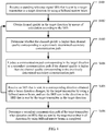
- FIG. 3 is a schematic interaction diagram of a communication method according to an embodiment of the present invention.
- This embodiment of the present invention is described by using communication between a BS (that is, a receiver) and UE (that is, a transmitter) as an example.
- the method includes:
- frame formats of uplink and downlink subframes corresponding to the UE in the beam on the primary communication path may be determined according to the secondary communication path that is corresponding to the UE in the beam on the primary communication path and that is obtained by means of determining, and then a communication path used for transmitting uplink and downlink subframes corresponding to each UE is determined, so that communication between the BS and the UE in the beam on the primary communication path is performed.
- a primary communication path for communication between a current BS and target UE that sends an SRS may be determined according to the SRS signal, and a secondary communication path may be determined for each UE that performs communication by using the primary communication path, so that communication with each UE is performed based on the primary communication path and the secondary communication path, which can effectively improve a data transmission throughput and data transmission efficiency of a system.
- FIG. 4 is a schematic flowchart of a method for determining a secondary communication path according to an embodiment of the present invention.
- the method in this embodiment of the present invention may be specifically applied to a communications device that can be used as a receiver, for example, a BS or an MS.
- the method includes:
- the target UE changes a beam direction according to a preset time interval, uses, as the target direction, a corresponding direction obtained after the beam direction changes, and sends an SRS in the target direction by using a fully deployed narrow beam. If the current BS receives the SRS that is sent by the target UE in the target direction, the current BS repeatedly executes S402 to S405 until the current BS completes detection on the SRSs that are sent by the target UE in all the directions by using the fully deployed narrow beams, and uses a determined secondary communication path as the secondary communication path between the current BS and the target UE.
- a current BS may compare channel quality in a direction at a current moment with channel quality in a direction at a previous moment to determine whether to update a secondary communication path corresponding to the target UE, and use a determined secondary communication path as a secondary communication path between the current BS and the target UE after the current BS completes detection on SRSs that are sent by the target UE in all directions according to a preset time interval by using fully deployed narrow beams.
- FIG. 5 is a schematic flowchart of another method for determining a secondary communication path according to an embodiment of the present invention. Specifically, the method includes:
- the current BS may select, as a secondary communication path corresponding to the target UE, a communication path corresponding to a direction with optimal channel quality of the channel quality in all the directions except channel quality in a direction of a primary communication path.
- the communication path corresponding to the direction with optimal channel quality except the channel quality in the direction of the primary communication path is determined as the secondary communication path corresponding to the target UE, whether the channel quality corresponding to the communication path is higher than a preset QoS threshold may be further detected; and if the channel quality corresponding to the communication path is higher than the QoS threshold, the communication path may be determined as the secondary communication path corresponding to the target UE.
- a BS may obtain channel quality in all the directions by means of calculation and comparison, and directly select, as a secondary communication path corresponding to the target UE, a communication path corresponding to a direction with optimal channel quality of the channel quality in all the directions except channel quality in a direction of a primary communication path.
- communication with a transmitter according to the primary communication path and a secondary communication path may include the following five communication scenarios:
- the primary communication path may be controlled to be used to transmit downlink subframes of the transmitters indicated by the identifiers, where the downlink subframes of the transmitters are transmitted in a frequency division multiplexing manner.
- the secondary communication path is controlled to be used to transmit an uplink subframe of a corresponding transmitter, where uplink subframes of the transmitters are transmitted in a spatial multiplexing manner, the uplink subframes of the transmitters exclusively occupy fully deployed bandwidth resources, and the uplink subframes and the downlink subframes of the transmitters are different in format.
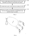
- FIG. 12 is a schematic diagram of still another communication scenario according to an embodiment of the present invention.
- there are multiple transmitters that perform communication by using the primary communication path that is, there are multiple transmitters in a beam corresponding to the primary communication path.
- there are two UEs in the beam corresponding to the primary communication path which are UE1 and UE2 respectively; the two UEs each have an available secondary communication path.
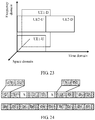
- FIG. 13 is a schematic diagram of resource allocation in the scenario in FIG. 12 . Specifically, uplinks of the UE1 and the UE2 in the beam on the primary communication path are distinguished in a space division manner, and downlinks of the two UEs are distinguished in a frequency division manner.
- the primary communication path may be controlled to be used only for downlink subframe transmission instead of uplink subframe transmission, and correspondingly, the secondary communication path is used only for uplink transmission instead of downlink subframe transmission.
- Frame formats of an uplink and a downlink of each UE are different and are independent of each other.
- FIG. 14 is a schematic diagram of a frame format in the scenario in FIG. 12 .
- the frame format in the scenario does not have a problem of a configuration ratio of quantities of uplink and downlink subframes.
- each uplink subframe U includes only information about the UE1 or the UE2, where the information is corresponding to U1 or U2 respectively.
- Each downlink subframe D may sequentially include information about the two UEs, that is, D1 and D2.
- a manner of inserting an SRS signal in this scenario is the same as the manner of inserting an SRS signal in the foregoing scenario, and details are not described herein. Further, an insertion spacing for the SRS signal may be adjusted according to a moving speed requirement.
- each UE has an available secondary communication path. All the UEs share downlink spectrum resources, and each UE exclusively uses uplink bandwidth resources. For example, for a spectrum with a bandwidth of 300 MHz, there are two UEs in the beam, where a downlink of each UE occupies a bandwidth of 150 MHz, and an uplink of each UE occupies a bandwidth of 300 MHz. Therefore, both a UE capacity and a system throughput are greatly improved.
- the primary communication path may be controlled to be used to transmit uplink subframes of the transmitters indicated by the identifiers, where the uplink subframes of the transmitters are transmitted in a frequency division multiplexing manner.
- the secondary communication path is controlled to be used to transmit a downlink subframe of a corresponding transmitter, where downlink subframes of the transmitters are transmitted in a spatial multiplexing manner, the downlink subframes of the transmitters exclusively occupy fully deployed bandwidth resources, and the uplink subframes and the downlink subframes of the transmitters are different in format.
- FIG. 15 is a schematic diagram of another type of resource allocation in the scenario in FIG. 12 .
- Downlinks of the UE1 and the UE2 in the beam on the primary communication path are distinguished in a space division manner, and uplinks of the two UEs are distinguished in a frequency division manner.
- the primary communication path may be controlled to be used only for uplink subframe transmission, and the secondary communication path may be controlled to be used only for downlink transmission.
- Frame formats of an uplink and a downlink of each UE are different and are independent of each other.
- FIG. 16 is a schematic diagram of another frame format in the scenario in FIG. 12 .
- Each downlink subframe D includes only information about the UE1 or the UE2, which is corresponding to D1 or D2 respectively; each uplink subframe U may sequentially include information about the two UEs, that is, U1 and U2.
- each UE has an available secondary communication path. All the UEs share uplink spectrum resources, and each UE exclusively uses downlink bandwidth resources. For example, for a spectrum with a bandwidth of 300 MHz, there are two UEs in the beam, where an uplink of each UE occupies a bandwidth of 150 MHz, and a downlink of each UE occupies a bandwidth of 300 MHz. Therefore, both a UE capacity and a system throughput are greatly improved.
- FIG. 20 is a schematic diagram of still yet another communication scenario according to an embodiment of the present invention.
- there are multiple transmitters that share the primary communication path that is, there are multiple transmitters in a beam corresponding to the primary communication path.
- the primary communication path may be controlled to be used to transmit downlink subframes of the transmitters, where the downlink subframes of the transmitters are transmitted in a frequency division multiplexing manner, and the transmitters include a first transmitter that does not have a secondary communication path, that is, the UE2, and a second transmitter that has a secondary communication path, that is, the UE1.
- the primary communication path is controlled to be used to transmit an uplink subframe of the first transmitter, where the uplink subframe of the first transmitter is transmitted in a frequency division multiplexing manner, and uplink and downlink subframes of the first transmitter are transmitted in a time division multiplexing manner.
- the secondary communication path is controlled to be used to transmit an uplink subframe of the second transmitter, where the uplink subframe of the second transmitter is transmitted in a spatial multiplexing manner, and the uplink subframe and a downlink subframe of the second transmitter are different in format.
- FIG. 21 is a schematic diagram of resource allocation in the scenario in FIG. 20 .
- downlinks of the UE1 and the UE2 in the beam on the primary communication path are distinguished in a frequency division manner
- an uplink and a downlink of the UE2 are distinguished in a time division manner
- an uplink and a downlink of the UE1 are distinguished in a space division manner.
- the primary communication path may be controlled to be used only for downlink subframe transmission
- the secondary communication path may be controlled to be used only for uplink subframe transmission.
- Frame formats of the uplink and the downlink of the UE1 are different and are independent of each other, and frame formats of the uplink and the downlink of the UE2 are the same.
- FIG. 22 is a schematic diagram of a frame format in the scenario in FIG. 20 . Because the UE1 and the UE2 share a downlink and a frame format of a downlink beam, when the UE2 transmits uplink data in a time division multiplexing manner, a bandwidth that belongs to the UE1 can be idle only.
- Quantities of uplink and downlink subframes may be configured according to a preset configuration ratio, for example, 4:4, and further, the configuration ratio may be adjusted according to throughputs of uplink and downlink services.
- a preset configuration ratio for example, 4:4
- the configuration ratio may be adjusted according to throughputs of uplink and downlink services.
- an uplink subframe U1 of the UE1 may be transmitted in a spatial multiplexing manner by using the secondary communication path
- the uplink subframe U1 of the UE1 has an independent frame format.
- each uplink subframe U1 transmitted by using the secondary communication path includes only information about the UE1;
- each downlink subframe D transmitted by using the primary communication path sequentially includes information about the UE1 and information about the UE2, that is, the information about the UE1 and the information about the UE2 are corresponding to D1 and D2 respectively.
- a frequency band that belongs to the UE1 is idle, and is represented by X in FIG. 22
- a frequency band that belongs to the UE2 includes information about the UE2, that is, the information about the UE2 is corresponding to U2.
- a manner of inserting an SRS signal in this scenario is the same as the manner of inserting an SRS signal in the foregoing scenario, and details are not described herein.
- An insertion spacing for the SRS signal may be adjusted according to a moving speed requirement.
- uplink data of the UE2 may be further controlled, by using a particular technology, to be sent in a bandwidth that is in an uplink subframe and of the UE1 in the primary communication path.
- each UE has an available secondary communication path. All the UEs share downlink spectrum resources, and UE that has a sub-optimal path exclusively uses uplink bandwidth resources. For example, for a spectrum with a bandwidth of 300 MHz, if the beam only includes the UE1 and the UE2, and only the UE1 has a corresponding secondary communication path, a downlink of each UE occupies a bandwidth of 150 MHz, an uplink of the UE2 occupies a bandwidth of 150 MHz, and an uplink of the UE1 occupies a bandwidth of 300 MHz. Therefore, both a UE capacity and a system throughput are greatly improved.
- the primary communication path may be controlled to be used to transmit uplink subframes of the transmitters, where the uplink subframes of the transmitters are transmitted in a frequency division multiplexing manner, and the transmitters include a first transmitter that does not have a secondary communication path, that is, the UE2, and a second transmitter that has a secondary communication path, that is, the UE1.
- the primary communication path is controlled to be used to transmit a downlink subframe of the first transmitter, where the downlink subframe of the first transmitter is transmitted in a frequency division multiplexing manner, and uplink and downlink subframes of the first transmitter are transmitted in a time division multiplexing manner.
- the secondary communication path is controlled to be used to transmit a downlink subframe of the second transmitter, where the downlink subframe of the second transmitter is transmitted in a spatial multiplexing manner, and an uplink subframe and the downlink subframe of the second transmitter are different in format.
- FIG. 23 is a schematic diagram of another type of resource allocation in the scenario shown in FIG. 20 .
- Uplinks of the UE1 and the UE2 in the beam on the primary communication path are distinguished in a frequency division manner, an uplink and a downlink of the UE2 are distinguished in a time division manner, and an uplink and a downlink of the UE1 are distinguished in a space division manner.
- the primary communication path may be controlled to be used only for uplink subframe transmission
- the secondary communication path may be controlled to be used only for downlink subframe transmission.
- Frame formats of the uplink and the downlink of the UE1 are different and are independent of each other, and frame formats of the uplink and the downlink of the UE2 are the same.
- FIG. 24 is a schematic diagram of another frame format in the scenario in FIG. 20 . Because the UE1 and the UE2 share an uplink and a frame format of an uplink beam, when the UE2 transmits downlink data in a time division multiplexing manner, a bandwidth that belongs to the UE1 can be idle only.
- Quantities of uplink and downlink subframes may be configured according to a preset configuration ratio, for example, 4:4, and further, the configuration ratio may be adjusted according to throughputs of uplink and downlink services.
- a downlink subframe U1 of the UE1 may be transmitted in a spatial multiplexing manner by using the secondary communication path
- the downlink subframe D1 of the UE1 has an independent frame format.
- each downlink subframe D1 transmitted by using the secondary communication path includes only information about the UE1;
- each uplink subframe U transmitted by using the primary communication path sequentially includes information about the UE1 and information about the UE2, that is, the information about the UE1 and the information about the UE2 are corresponding to U1 and U2 respectively.
- a frequency band that belongs to the UE1 that is, X in FIG. 24 , is idle, and a frequency band that belongs to the UE2 includes information about the UE2, that is, the information about the UE2 is corresponding to D2.
- downlink data of the UE2 may be further controlled, by using a particular technology, to be sent in a bandwidth that is in a downlink subframe and of the UE1 in the primary communication path.
- each UE there are multiple UEs in a beam, but not each UE has an available secondary communication path. All the UEs share uplink spectrum resources, and UE that has a sub-optimal path exclusively uses downlink bandwidth resources. For example, for a spectrum with a bandwidth of 300 MHz, if the beam only includes the UE1 and the UE2, and only the UE1 has a corresponding secondary communication path, an uplink of each UE occupies a bandwidth of 150 MHz, a downlink of the UE2 occupies a bandwidth of 150 MHz, and a downlink of the UE1 occupies a bandwidth of 300 MHz. Therefore, both a UE capacity and a system throughput are greatly improved.
- a frame format is determined according to a specific communication scenario, and after communication paths (including a primary communication path and a corresponding secondary communication path) used for transmitting uplink and downlink subframes are determined for each UE, communication between a BS and the UE may be prepared to be performed.
- a current BS may further determine a secondary communication path to the UE, extract a secondary communication path of another UE existing in a beam on the primary communication path, and communicate with each UE in the beam on the primary communication path based on a communication scenario that is determined according to the primary communication path and the secondary communication path, which can effectively improve a data transmission throughput and data transmission efficiency of a system.
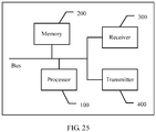
- FIG. 25 is a schematic structural diagram of a communications device according to an embodiment of the present invention.
- the communications device in this embodiment of the present invention includes: a receiver 300, a transmitter 400, a memory 200, and a processor 100, where the memory 200 may be a high-speed RAM memory, or may be a non-volatile memory (non-volatile memory), for example, at least one magnetic disk memory.
- the memory 200 stores a corresponding application program and the like.
- Data connection may be performed among the receiver 300, the transmitter 400, the memory 200, and the processor 100 by using a bus, or in another manner. Connection performed by using a bus is described in this embodiment.
- the communications device in this embodiment of the present invention may include the foregoing communications apparatus and may be specifically corresponding to a device that can be used as a receiver, for example, a BS or an MS.
- the processor 100 executes the following steps:
- the processor 100 when executing the determining a primary communication path to a target transmitter according to a first SRS when the first SRS is received, the processor 100 specifically executes the following steps:
- the processor 100 when executing the obtaining an identifier of a transmitter that performs communication by using the primary communication path, and determining a secondary communication path of a transmitter indicated by each identifier, the processor 100 specifically executes the following steps:
- the processor 100 when executing the obtaining the identifier of the transmitter that performs communication by using the primary communication path, and determining a secondary communication path of the target transmitter according to a second SRS that is sent by the target transmitter corresponding to a target identifier in the identifiers, the processor 100 specifically executes the following steps:
- the processor 100 when executing the updating a communication path corresponding to the target direction to a secondary communication path, the processor 100 specifically executes the following steps:
- the target transmitter changes a beam direction according to a preset time interval, uses, as the target direction, a corresponding direction obtained after the beam direction changes, and sends an SRS in the target direction by using a fully deployed narrow beam.
- the receiver receives an SRS sent by target UE in the target direction, calculates and determines channel quality in the direction until detection on SRSs sent by the target UE in all directions is completed, and then may use a determined secondary communication path as a secondary communication path between the current BS and the target UE.
- the processor 100 when executing the communicating with the transmitter according to the primary communication path and the secondary communication path, the processor 100 specifically executes the following steps:
- the processor 100 when executing the communicating with the transmitter according to the primary communication path and the secondary communication path, the processor 100 specifically executes the following steps:
- the processor 100 when executing the communicating with the transmitter according to the primary communication path and the secondary communication path, the processor 100 specifically executes the following step:
- the processor 100 when executing the communicating with the transmitter according to the primary communication path and the secondary communication path, the processor 100 specifically executes the following steps:
- the processor 100 when executing the communicating with the transmitter according to the primary communication path and the secondary communication path, the processor 100 specifically executes the following steps:
- processor 100 further executes the following step:
- a primary communication path for communication between a current transmitter and a target transmitter may be determined according to an SRS signal received by a receiver, and a secondary communication path is determined for each transmitter that performs communication by using the primary communication path, so that communication with each transmitter is performed based on the primary communication path and the secondary communication path, which effectively improves a system transmission capacity.
- the program may be stored in a computer readable storage medium.
- the storage medium may be: a magnetic disk, an optical disc, a read-only memory (English full name: Read-Only Memory, ROM for short), a random access memory (English full name: Random Access Memory, RAM for short), or the like.
Landscapes
- Engineering & Computer Science (AREA)
- Signal Processing (AREA)
- Computer Networks & Wireless Communication (AREA)
- Mobile Radio Communication Systems (AREA)
Applications Claiming Priority (1)
| Application Number | Priority Date | Filing Date | Title |
|---|---|---|---|
| PCT/CN2014/080095 WO2015192318A1 (fr) | 2014-06-17 | 2014-06-17 | Procédé et dispositif de communication |
Publications (2)
| Publication Number | Publication Date |
|---|---|
| EP3148280A1 true EP3148280A1 (fr) | 2017-03-29 |
| EP3148280A4 EP3148280A4 (fr) | 2017-08-30 |
Family
ID=54934673
Family Applications (1)
| Application Number | Title | Priority Date | Filing Date |
|---|---|---|---|
| EP14895407.6A Withdrawn EP3148280A4 (fr) | 2014-06-17 | 2014-06-17 | Procédé et dispositif de communication |
Country Status (7)
| Country | Link |
|---|---|
| US (1) | US20170099694A1 (fr) |
| EP (1) | EP3148280A4 (fr) |
| JP (1) | JP2017527150A (fr) |
| KR (1) | KR20170018440A (fr) |
| CN (1) | CN106465414A (fr) |
| BR (1) | BR112016029450A2 (fr) |
| WO (1) | WO2015192318A1 (fr) |
Families Citing this family (5)
| Publication number | Priority date | Publication date | Assignee | Title |
|---|---|---|---|---|
| US9980271B2 (en) * | 2015-03-14 | 2018-05-22 | Qualcomm Incorporated | Interference aware reciprocal channel sounding reference signal |
| EP3400732B1 (fr) * | 2016-01-08 | 2020-08-26 | Commscope Technologies LLC | Système et procédé d'agrégation de porteuses utilisant la formation de faisceau |
| US11477771B2 (en) * | 2016-04-05 | 2022-10-18 | Qualcomm Incorporated | Indicating start and stop symbols of PDSCH and PUSCH through PDCCH |
| CN112770338B (zh) * | 2019-10-21 | 2022-11-04 | 华为技术有限公司 | 通信方法和通信装置 |
| KR102432021B1 (ko) * | 2021-09-07 | 2022-08-16 | 스카이루먼 주식회사 | 중계드론과 임무드론 간의 보안 통신 방법 |
Family Cites Families (11)
| Publication number | Priority date | Publication date | Assignee | Title |
|---|---|---|---|---|
| JP3961660B2 (ja) * | 1998-03-02 | 2007-08-22 | 株式会社日立製作所 | 通信接続切替方法及び通信接続切替装置 |
| KR100891789B1 (ko) * | 2006-01-04 | 2009-04-07 | 삼성전자주식회사 | 무선 통신 시스템에서 신호 송수신 장치 및 방법 |
| US9806789B2 (en) * | 2010-04-06 | 2017-10-31 | Samsung Electronics Co., Ltd. | Apparatus and method for spatial division duplex (SDD) for millimeter wave communication system |
| US8504052B2 (en) * | 2010-05-06 | 2013-08-06 | Nokia Corporation | Measurements and fast power adjustments in D2D communications |
| US9131457B2 (en) * | 2010-08-12 | 2015-09-08 | Samsung Electronics Co., Ltd. | Apparatus and method for transmission of uplink sounding reference signals in a wireless network |
| US8743802B2 (en) * | 2010-11-08 | 2014-06-03 | Blackberry Limited | Allocating wireless resources |
| US9232550B2 (en) * | 2011-03-31 | 2016-01-05 | Broadcom Corporation | Method and apparatus for facilitating device-to-device communication |
| US9585083B2 (en) * | 2011-06-17 | 2017-02-28 | Samsung Electronics Co., Ltd. | Apparatus and method for supporting network entry in a millimeter-wave mobile broadband communication system |
| EP2727257B1 (fr) * | 2011-07-01 | 2015-10-28 | Telefonaktiebolaget L M Ericsson (PUBL) | Formation de faisceau avec compensation de phase |
| WO2013015587A2 (fr) * | 2011-07-22 | 2013-01-31 | 엘지전자 주식회사 | Procédé permettant de déterminer une sous-trame dans un système de communication sans fil |
| US9351288B2 (en) * | 2012-06-05 | 2016-05-24 | Samsung Electronics Co., Ltd. | Uplink channel sounding and channel state information estimation in mobile communication systems with multiple antennas |
-
2014
- 2014-06-17 WO PCT/CN2014/080095 patent/WO2015192318A1/fr not_active Ceased
- 2014-06-17 KR KR1020177001199A patent/KR20170018440A/ko not_active Ceased
- 2014-06-17 BR BR112016029450A patent/BR112016029450A2/pt not_active IP Right Cessation
- 2014-06-17 CN CN201480078908.2A patent/CN106465414A/zh active Pending
- 2014-06-17 JP JP2016573974A patent/JP2017527150A/ja not_active Withdrawn
- 2014-06-17 EP EP14895407.6A patent/EP3148280A4/fr not_active Withdrawn
-
2016
- 2016-12-16 US US15/381,273 patent/US20170099694A1/en not_active Abandoned
Also Published As
| Publication number | Publication date |
|---|---|
| JP2017527150A (ja) | 2017-09-14 |
| WO2015192318A1 (fr) | 2015-12-23 |
| KR20170018440A (ko) | 2017-02-17 |
| CN106465414A (zh) | 2017-02-22 |
| BR112016029450A2 (pt) | 2017-08-22 |
| EP3148280A4 (fr) | 2017-08-30 |
| US20170099694A1 (en) | 2017-04-06 |
Similar Documents
| Publication | Publication Date | Title |
|---|---|---|
| US11930469B2 (en) | Timing advance in full-duplex communication | |
| US12101157B2 (en) | Beam correspondence indication and bitmap for beam reporting for wireless communications | |
| US12155589B2 (en) | Method for transmitting information element, communication node, system and storage medium | |
| EP1958351B1 (fr) | Dispositif point a multipoint pour communication avec plusieurs unites de telecommunication | |
| US11985617B2 (en) | Full duplex timing advance enhancements | |
| JP6639699B2 (ja) | ビームフォーミング済み信号を利用した通信システムにおける初期アタッチメントのためのシステムおよび方法 | |
| US20200178309A1 (en) | Method and apparatus for non-contention based random access | |
| KR102238768B1 (ko) | 무선통신 시스템의 상향링크 동기화 장치 및 방법 | |
| EP3273730A1 (fr) | Dispositif d'utilisateur et station de base | |
| EP3188547B1 (fr) | Partage d'une antenne dans un terminal | |
| EP4410016B1 (fr) | Atténuation intelligente des interférences pour réseaux à large bande à duplexage par répartition dans le temps | |
| US20170099694A1 (en) | Communication Method and Communications Apparatus | |
| US20150305025A1 (en) | SYSTEM AND METHOD OF SIGNALLING FOR POINT-TO-MULTIPOINT (PtMP) TRANSMISSION IN FIXED WIRELESS BACKHAUL NETWORKS | |
| JP2025532154A (ja) | リピータ、端末デバイス、及びネットワークデバイス | |
| JP2024504942A (ja) | 基地局及び通信方法 | |
| EP4136902A1 (fr) | Procédé et noeud de réseau pour réduire l'impact d'un brouillage | |
| US20150055520A1 (en) | Base station and communication control method | |
| KR20250008091A (ko) | 무선 통신 시스템에서 사용자 단말 탐지를 위한 방법 및 장치 |
Legal Events
| Date | Code | Title | Description |
|---|---|---|---|
| PUAI | Public reference made under article 153(3) epc to a published international application that has entered the european phase |
Free format text: ORIGINAL CODE: 0009012 |
|
| 17P | Request for examination filed |
Effective date: 20161219 |
|
| AK | Designated contracting states |
Kind code of ref document: A1 Designated state(s): AL AT BE BG CH CY CZ DE DK EE ES FI FR GB GR HR HU IE IS IT LI LT LU LV MC MK MT NL NO PL PT RO RS SE SI SK SM TR |
|
| AX | Request for extension of the european patent |
Extension state: BA ME |
|
| RIC1 | Information provided on ipc code assigned before grant |
Ipc: H04W 72/04 20090101ALI20170424BHEP Ipc: H04B 7/06 20060101ALI20170424BHEP Ipc: H04L 5/00 20060101ALI20170424BHEP Ipc: H04W 24/08 20090101ALI20170424BHEP Ipc: H04W 76/02 20090101ALI20170424BHEP Ipc: H04W 16/28 20090101ALI20170424BHEP Ipc: H04W 74/00 20090101AFI20170424BHEP Ipc: H04W 76/00 20090101ALI20170424BHEP |
|
| A4 | Supplementary search report drawn up and despatched |
Effective date: 20170801 |
|
| RIC1 | Information provided on ipc code assigned before grant |
Ipc: H04W 76/02 20090101ALI20170726BHEP Ipc: H04W 16/28 20090101ALI20170726BHEP Ipc: H04B 7/06 20060101ALI20170726BHEP Ipc: H04W 72/04 20090101ALI20170726BHEP Ipc: H04L 5/00 20060101ALI20170726BHEP Ipc: H04W 24/08 20090101ALI20170726BHEP Ipc: H04W 74/00 20090101AFI20170726BHEP Ipc: H04W 76/00 20090101ALI20170726BHEP |
|
| DAX | Request for extension of the european patent (deleted) | ||
| STAA | Information on the status of an ep patent application or granted ep patent |
Free format text: STATUS: THE APPLICATION IS DEEMED TO BE WITHDRAWN |
|
| 18D | Application deemed to be withdrawn |
Effective date: 20180301 |