EP3148325B1 - Procédé et installation en circuit fermé pour la stabulation d'organismes aquatiques - Google Patents
Procédé et installation en circuit fermé pour la stabulation d'organismes aquatiques Download PDFInfo
- Publication number
- EP3148325B1 EP3148325B1 EP15726912.7A EP15726912A EP3148325B1 EP 3148325 B1 EP3148325 B1 EP 3148325B1 EP 15726912 A EP15726912 A EP 15726912A EP 3148325 B1 EP3148325 B1 EP 3148325B1
- Authority
- EP
- European Patent Office
- Prior art keywords
- air
- water
- circulation system
- holding
- line
- Prior art date
- Legal status (The legal status is an assumption and is not a legal conclusion. Google has not performed a legal analysis and makes no representation as to the accuracy of the status listed.)
- Not-in-force
Links
Images




Classifications
-
- A—HUMAN NECESSITIES
- A01—AGRICULTURE; FORESTRY; ANIMAL HUSBANDRY; HUNTING; TRAPPING; FISHING
- A01K—ANIMAL HUSBANDRY; AVICULTURE; APICULTURE; PISCICULTURE; FISHING; REARING OR BREEDING ANIMALS, NOT OTHERWISE PROVIDED FOR; NEW BREEDS OF ANIMALS
- A01K63/00—Receptacles for live fish, e.g. aquaria; Terraria
- A01K63/003—Aquaria; Terraria
-
- A—HUMAN NECESSITIES
- A01—AGRICULTURE; FORESTRY; ANIMAL HUSBANDRY; HUNTING; TRAPPING; FISHING
- A01K—ANIMAL HUSBANDRY; AVICULTURE; APICULTURE; PISCICULTURE; FISHING; REARING OR BREEDING ANIMALS, NOT OTHERWISE PROVIDED FOR; NEW BREEDS OF ANIMALS
- A01K63/00—Receptacles for live fish, e.g. aquaria; Terraria
- A01K63/04—Arrangements for treating water specially adapted to receptacles for live fish
-
- A—HUMAN NECESSITIES
- A01—AGRICULTURE; FORESTRY; ANIMAL HUSBANDRY; HUNTING; TRAPPING; FISHING
- A01K—ANIMAL HUSBANDRY; AVICULTURE; APICULTURE; PISCICULTURE; FISHING; REARING OR BREEDING ANIMALS, NOT OTHERWISE PROVIDED FOR; NEW BREEDS OF ANIMALS
- A01K63/00—Receptacles for live fish, e.g. aquaria; Terraria
- A01K63/04—Arrangements for treating water specially adapted to receptacles for live fish
- A01K63/042—Introducing gases into the water, e.g. aerators, air pumps
-
- A—HUMAN NECESSITIES
- A01—AGRICULTURE; FORESTRY; ANIMAL HUSBANDRY; HUNTING; TRAPPING; FISHING
- A01K—ANIMAL HUSBANDRY; AVICULTURE; APICULTURE; PISCICULTURE; FISHING; REARING OR BREEDING ANIMALS, NOT OTHERWISE PROVIDED FOR; NEW BREEDS OF ANIMALS
- A01K63/00—Receptacles for live fish, e.g. aquaria; Terraria
- A01K63/06—Arrangements for heating or lighting in, or attached to, receptacles for live fish
- A01K63/065—Heating or cooling devices
Definitions
- the invention relates to a method for keeping fish or other species living in the water in a circulation system with at least one holding tank, at least one biological filter and optionally further water treatment units, e.g. for introducing oxygen for sterilizing, for defoaming, for mechanical filtering etc.
- the invention relates to a circulation system.
- the warm-blooded fish requires 1.4 kg feed per kilogram increase, poultry 1.5-2.0 kg, pigs 2.5-4.5 kg and cattle 5.5-10 kg feed per kilogram increase.
- Asian economies in particular are largely based on the production of crustaceans and shellfish.
- high levels of chemicals and antibiotics are used in production to keep production stable.
- the way out of these production regions into the target markets is far and can therefore only be bridged in the frozen condition of the goods.
- the investments suitable for this purpose result in an investment that results in the proceeds no longer covering the expense.
- the essential cost component in the rearing of fish in extensive fish farming is the land consumption for the necessary storage tanks.
- India has banned offshore conversion of land to fish farms.
- Even with intensive fish farming in recirculation systems, the provision of the storage tanks requires a great financial outlay.
- the basins are prefabricated, for example made of resin-bonded concrete and the items then joined together at the site. The production of these high-precision finished parts and the transport to the construction site and their assembly are essential cost elements.
- matrix material come from the dentistry known plastics are used, which additionally increase the cost of production.
- the US 8651058 B1 concerns a system for aquaculture in closed tanks. For this purpose, gas discharged from the water is sucked by a suction from the air space of the tank. An aerator pumps fresh air to a bubbler to disperse the air in the water. Resulting decomposition products in the water are fed to plants for cleaning.
- the US2008028667 A1 relates to a device for the portable keeping of live baits, such as fish.
- the device comprises an internal water-filled bait container, an outer container enclosing this.
- a gap is filled with an ice water mixture as a heat or cold buffer.
- the ventilation arrangement comprises a line section, which is passed through a heat or cold buffer and ends in the amount of water to ventilate it.
- the air flow which has been tempered by the line section, aerates the amount of water and allows heat transfer between the air and the amount of water to control the air and / or water temperature to keep the bait alive.
- the DE 2851808 A1 relates to a device for a fish water, which is heated by supplying energy. For further warming beyond its natural temperature level, the exploitation of a natural heat potential is proposed, such as heating by means of solar panels that float. It is also proposed, by means of a device, to blow in warm air in order to heat and increase the oxygen content of the water.
- the object of the invention is therefore to propose a method and a circulation system for the management of aquatic organisms, which significantly reduce the operating costs with less technical effort.
- foamed plastic with an outer plastic reinforcement is used as the material for producing the basins and / or the water treatment units.
- the foamed material is also used to cover the holding tank and possibly also to cover other water treatment units.
- a recirculation plant for the management of fish and other living organisms in the water is created, which is surprisingly easy to produce and is easily scalable for future growing production volumes.
- the plant according to the invention allows a rearing of marine life even under the conditions of a temperate climate.
- the plant offers special advantages for circulating plants with a temperature of about 30 ° C, which is suitable for growing shrimp tanks, in particular of the species Litopaeneus Vanamei.
- the cut according to FIG. 1 shows the foam plate 12 with the reinforced surfaces 13.
- reinforcement serves a glass fiber network 36 of the vertical section only the weft threads 37 can be seen.
- This fiberglass net is embedded within a material matrix 38 which firmly bonds the glass fiber net to the foam sheet 12, preferably a polystyrene foam.
- the material matrix 38 is a resin-bonded concrete.
- a pressure armor 39 made of a resin-bonded fine plaster is shown on one side. This reinforcement 39 absorbs the resulting compressive stress under bending stress and vertical load while the glass fiber network 36 on the underside ablates the resulting tensile stresses.
- FIG. 2 shows a plan view of the double-sided reinforced foam plate 12: In this view, the warp threads 40 of the fiber optic network 36 are visible.
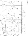
- the circuit diagram of a circulation system 1 according to the invention is shown in FIG FIG. 3 shown.
- this scheme which can also be interpreted as a plan view, the essential components of the system in the form of different modules 14 are shown. Nevertheless, this scheme does not claim to be exhaustive. Some components are missing. For example, there is a lack of pH adjustment and heating.
- the central component of a circulation system is the storage tank 2.
- three parallel connected storage tanks 2 are shown.
- the cisterns are via an inlet 16 to the line 41 with purified Water connected.
- the effluent from the basin 2 water to the hot water line 43 is performed. This results in a flow in the direction 44 in the basin.
- the pressure difference necessary to maintain this flow is generated by the circulation pump 45, which pumps the water from line 43 into line 41.
- this cycle can only be used for a short time with stocking. It can only be operated until the substances introduced into the water by excretion reach lethal concentrations for stocking.
- a biological filter unit 3 is connected in series with the parallel-connected holding basins 2.
- the pumped from pump 46 hot water is first subjected to module 8 in a mechanical filtering. Subsequently, the water is then fed to a water treatment unit for nitrification 28.
- a partial flow via line 47 of a water treatment unit for denitrification 26 is supplied. After treatment, the partial stream is reunited with the parting stream leaving the nitrification via line 48, in order then to be freed of protein in the skimmer 7 and finally to collect in the feed basin 49. There is via line 50, which from the Circulation discharged water supplemented.
- the filtrate produced in the mechanical filter stage 8 is fed via line 51 to a sedimentation tank 52 into which the protein / water mixture withdrawn from the defoamer 7 is also passed via line 53.
- the collected in sales basin 52 wastewater can be fed to the sewer.
- Via line 55 clarified water from the sales tank 52 is recycled.
- the air for the nitrification, which flows through the module 28, is preferably removed by the blower 56 via line 29 from the cavity 30 between the water surface and cover of the holding basin and then pushed through the module 28.
- the exhaust air passes via line 32 to the induced draft 58, which presses the exhaust air through the recuperator 33.
- the air then exits via line 59 into the atmosphere.
- the recuperator 33 heats the air entering through intake 60 via a heat exchanger.
- This air is first supplied from the blower 61 via lines 50 and 62 as fresh air to the tank 2. Above the water surface of the basins 2, therefore, an air flow opposite to the water flow preferably results in the direction 63.
- the air supplied to the basins can be used to oxygenate the containment water and expel other gases such as nitrogen and carbon dioxide.
- FIGS. 4 and 5 are schematized, ie in FIG. 4 as supervision, FIG. 5 as a vertical section, the in FIG. 3 shown modules of the biological filter unit partially shown.
- the left-hand module 4 is intended to represent the flow basin 49.
- the water enters via connecting line 91 in the water treatment unit 5 for the input of oxygen.
- the oxygen-enriched water is passed through the further connection line 91 in the water treatment unit for sterilizing 6.
- From the degerming station 6 then enters the water via the connecting line 91 in the holding tank 2 a. ( FIG. 4 ).
- submersible pumps 65 can additionally be provided in the shafts 19 to switch the water in dependence on the signals from one or more level monitors 66.
- These level switches 66 can be conveniently mounted in the shafts 19 at the required height. In this way, each module can be equipped with a simple hard-wired control that automatically turns the pumps on and off depending on the water level.
- Such a primitive controller has a much higher reliability than modern programmable logic controllers.
- FIG. 6 shows the outside view of such linkable modules 14.
- Each module has its own on-off switch 67.
- each module via a supply cable with connector 68, which is plugged into the switchable socket 69 of the adjacent module.
- the signals of the level monitor are provided to the adjacent, so that a submersible pump disposed in a shaft can be switched in response to the switching signals from the controller.
- Hydraulically and the water cycle 22 is closed by the submersible pumps 65.
- one module can be switched as master 23 and the others as slaves 24.
- the modules formed in this way can also be electrically connected to form a ring structure.
- a connection to an emergency power supply is established to the controller operated at low-voltage level.
- an emergency generator with internal combustion engine must be made available for emergency power supply operated with the usual mains voltage blower, pumps and the like.
- FIG. 6 left unit serves for denitrification. Therefore, a blower 72 is shown that sucks existing inert gas out of the module and blows back into the module 14 via line 73.
- the modules 14 in FIG. 6 Both stand with their bottom 9 on blocks 74. Between these and the floor level 64, thus forming a pocket 35, in which the tines of a forklift can be retracted. The module can thus be easily moved.
- FIG. 6 illustrated left module 14, the denitrification unit 26 of the circulation water, is shown as a vertical section in FIG. 7 and as a supervisor in FIG. 8 shown.
- the blower 72 is mounted on the cover 11.
- Cover 11 is designed as a hood 27, which dips with its lower edge in the water level 76 and thus forms a gas space 77, from which the fan 72 can subtract the inert gas to press it via line 73 back into the central tube 78. There, the gas bubbles rupture body and the water with and circulate this content.
- the corners 20 and 21, which are diagonally opposite each other shafts 19 are provided in which submersible pumps, monitors or gauges can be attached.
- the axial directions 18 of the inlet 16 and the outlet 17 are aligned parallel to each other and are perpendicular to the respective conversions. Inlet and outlet 16,17 each open in a shaft 19th
- a module 14 is shown as nitrification unit 28.
- nitrification unit 28 Such a unit is fundamentally similar to the one in the FIGS. 7 and 8 shown unit.
- air is sucked in by the blower 56 and no inert gas is forced into the module.
- the air comes through the suction line 29 air from the cavity 30 (FIG. FIG. 5 ) below the cover 31 (FIG. FIG. 5 ) and is then injected via line 73 again below the water level 76 in the module.
- the supplied air can be conducted as exhaust air into an exhaust air line 32, from the induced draft 58 discharges the exhaust air through the recuperator 33 and through line 59 into the atmosphere ( FIG. 3 ).
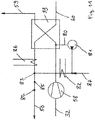
- FIG. 11 shows the scheme for conditioning the supply air.
- the induced draft 58 sucks the exhaust air from line 32 and pushes them through the air-to-air heat exchanger 33 via line 59 into the atmosphere.
- the exhaust air is cooled by the inlet air flowing through line 60, so that condensate forms in the run-off, which is fed via condensate line 80 of the pump 81.
- a humidity sensor 84 in line 50 measures the degree of saturation of the supply air, so that the humidity supply air at the temperature measured by temperature sensor 85 regulated can be. If necessary, the temperature of the supply air can be increased by heating 86. If the accumulating condensate is insufficient to saturate the supply air, then fresh water line 87 can also be used to condition the supply air with other water.
Landscapes
- Life Sciences & Earth Sciences (AREA)
- Environmental Sciences (AREA)
- Marine Sciences & Fisheries (AREA)
- Animal Husbandry (AREA)
- Biodiversity & Conservation Biology (AREA)
- Purification Treatments By Anaerobic Or Anaerobic And Aerobic Bacteria Or Animals (AREA)
- Farming Of Fish And Shellfish (AREA)
Claims (15)
- Procédé de maintien de poissons ou d'autres espèces vivant dans l'eau dans un circuit fermé (1) doté d'au moins un bassin de maintien (2), d'au moins un filtre biologique (3) ainsi que, le cas échéant, d'unités supplémentaires de traitement de l'eau (4) par exemple pour l'oxygénation (5), pour la désinfection (6), pour l'écumage (7), pour la filtration mécanique (8), dans lequel, l'air entrant est amené, par au moins un conduit d'entrée d'air (60) dans le circuit au-dessus du niveau de l'eau dans un espace vide (30) aménagé dans le bassin de maintien (2) et l'air sortant est évacué par au moins un conduit de sortie d'air (59) hors du dessus du niveau de l'eau dans l'espace vide (30) aménagé dans le bassin de maintien (2), caractérisé en ce que l'air entrant et sortant sont conduits au travers d'un échangeur de chaleur (33), dans lequel la chaleur contenue par l'air sortant est transmise à l'air entrant et/ou l'air entrant est élevé au niveau de température du bassin de maintien.
- Procédé de maintien de poissons ou d'autres espèces vivant dans l'eau dans un circuit fermé selon la revendication 1, caractérisé en ce que l'air entrant est humidifié, de préférence jusqu'à saturation, en particulier par utilisation du condensat obtenu.
- Procédé de maintien de poissons ou d'autres espèces vivant dans l'eau dans un circuit fermé selon la revendication 1 ou 2, caractérisé en ce que le bassin de maintien et au moins une unité de traitement de l'eau sont couplés en parallèle aux conduits d'entrée d'air et de sortie d'air.
- Procédé de maintien de poissons ou d'autres espèces vivant dans l'eau dans un circuit fermé selon la revendication 1, 2 ou 3 caractérisé en ce que pour l'enrichissement en oxygène de l'eau une aération par insufflation d'air se produit, de préférence au moyen d'un aérateur statique à plaques ondulées (5).
- Procédé de maintien de poissons ou d'autres espèces vivant dans l'eau dans un circuit fermé selon la revendication 1, 2, 3 ou 4 caractérisé en ce que l'air entrant à l'état préchauffé est conduit dans l'espace vide (30) en dessous d'un couvercle (11) du bassin de maintien (2).
- Moteur Procédé de maintien de poissons ou d'autres espèces vivant dans l'eau dans un circuit fermé selon la revendication 1, 2, 3, 4 ou 5 caractérisé en ce que le condensat produit dans l'échangeur de chaleur (33) est injecté dans le circuit d'eau.
- Procédé de maintien de poissons ou d'autres espèces vivant dans l'eau dans un circuit fermé selon l'une des revendications précédentes caractérisé en ce qu'au moins le bassin (2) et/ou le filtre biologique (3) comporte un couvercle (11), dans lequel résulte un espace vide (30) entre le niveau de l'eau et le couvercle du bassin de maintien, depuis lequelle de l'air est évacué au moyen d'un conduit (29) et poussé au travers du filtre (28) pour la nitrification.
- Procédé de maintien de poissons ou d'autres espèces vivant dans l'eau dans un circuit fermé selon l'une des revendications précédentes caractérisé en ce que l'air est conduit depuis un ventilateur (61) au moyen de conduits (50 et 62) en tant qu'air frais, d'abord à un bassin (2), au-dessus du niveau de l'eau, de préférence, de sorte qu'un flux d'air se produit dans le sens contraire du flux d'eau.
- Procédé de maintien de poissons ou d'autres espèces vivant dans l'eau dans un circuit fermé selon l'une des revendications précédentes caractérisé en ce que l'air nécessaire pour une étape de nitrification est aspiré de l'espace vide (30) au-dessus d'un bassin (2) et est saturé de vapeur d'eau et amené approximativement à la température de l'eau d'une étape de nitrification (28).
- Procédé de maintien de poissons ou d'autres espèces vivant dans l'eau dans un circuit fermé selon l'une des revendications précédentes caractérisé en ce que l'air est réinsufflé, au moyen d'un conduit d'aspiration (29) et du conduit (73), sous le niveau de l'eau (76) dans le module de nitrification (28) depuis l'espace vide (30) du bassin (figure 5) sous le couvercle (31)(figure 5) et est conduit par une ouverture (79) comme air sortant dans un conduit d'air sortant (32), d'où une aspiration (58) évacue l'air sortant dans l'atmosphère au travers de l'échangeur de chaleur (33).
- Circuit fermé de maintien de poissons ou d'autres espèces vivant dans l'eau, en particulier pour la mise en oeuvre d'un procédé selon l'une des revendications précédentes 1 à 10, dans lequel le circuit fermé comporte au moins un conduit d'air entrant (60) pour faire entrer l'air frais et un conduit d'air sortant (59) pour évacuer l'air sortant, dans lequel des conduits de raccordement sont prévus vers l'espace vide (30) situé au-dessus du niveau d'eau du bassin de maintien (2), vers au moins un filtre biologique (3) ainsi que, le cas échéant, des unités supplémentaires de traitement de l'eau (4) par exemple pour l'oxygénation (5), pour la désinfection (6), pour l'écumage (7), pour la filtration mécanique (8), pour un échange d'air, et caractérisé en ce qu'un échangeur de chaleur (33) est prévu afin de récupérer la chaleur de l'air sortant et de chauffer l'air entrant au niveau de le température du bassin de maintien.
- Circuit fermé selon la revendication 11, caractérisé en ce qu'au moins un module (14), en particulier une unité de traitement de l'eau pour la dénitrification (26) et/ou la nitrification (28), est doté d'au moins une coiffe (27) partiellement immergée.
- Circuit fermé selon une des revendications précédentes 11 ou 12, caractérisé en ce qu'au moins un module (14), en particulier une unité de traitement de l'eau pour la nitrification (28), comporte un conduit d'aspiration (29) raccordé à un espace vide (30) sous le couvercle (31) du bassin du maintien (2).
- Circuit fermé selon une des revendications précédentes 11 à 13, caractérisé en ce qu'au moins un module (14), en particulier une unité de traitement de l'eau pour la nitrification (28), comporte un conduit d'air sortant (32) vers un échangeur de chaleur, dans lequel l'échangeur de chaleur (33) comporte un conduit d'admission (34) pour l'air frais raccordé à un espace vide (30) sous le couvercle (31) du bassin du maintien (2).
- Circuit fermé selon une des revendications précédentes 11 à 14, caractérisé en ce qu'un aérateur par insufflation d'air (5) est prévu pour l'enrichissement en oxygène de l'eau.
Applications Claiming Priority (2)
| Application Number | Priority Date | Filing Date | Title |
|---|---|---|---|
| DE102014107431.9A DE102014107431A1 (de) | 2014-05-27 | 2014-05-27 | Verfahren und Kreislaufanlage zur Hälterung von Wasserlebewesen |
| PCT/EP2015/061674 WO2015181218A1 (fr) | 2014-05-27 | 2015-05-27 | Procédé et installation en circuit fermé pour la stabulation d'organismes aquatiques |
Publications (2)
| Publication Number | Publication Date |
|---|---|
| EP3148325A1 EP3148325A1 (fr) | 2017-04-05 |
| EP3148325B1 true EP3148325B1 (fr) | 2018-04-04 |
Family
ID=53284227
Family Applications (1)
| Application Number | Title | Priority Date | Filing Date |
|---|---|---|---|
| EP15726912.7A Not-in-force EP3148325B1 (fr) | 2014-05-27 | 2015-05-27 | Procédé et installation en circuit fermé pour la stabulation d'organismes aquatiques |
Country Status (3)
| Country | Link |
|---|---|
| EP (1) | EP3148325B1 (fr) |
| DE (2) | DE102014107431A1 (fr) |
| WO (1) | WO2015181218A1 (fr) |
Cited By (1)
| Publication number | Priority date | Publication date | Assignee | Title |
|---|---|---|---|---|
| DE102022004039A1 (de) * | 2022-10-29 | 2024-05-02 | Gerhard Vonnemann | Aquakulturbecken |
Families Citing this family (2)
| Publication number | Priority date | Publication date | Assignee | Title |
|---|---|---|---|---|
| CN108834978A (zh) * | 2018-08-13 | 2018-11-20 | 上海海洋大学 | 一种气提推水折回式全塘流动的蟹塘养殖自净系统 |
| DE102021006242A1 (de) * | 2021-12-19 | 2023-06-22 | Gerhard Vonnemann | Aquakulturlangstrombecken und Verfahren zum Betrieb eines Langstrombeckens |
Family Cites Families (15)
| Publication number | Priority date | Publication date | Assignee | Title |
|---|---|---|---|---|
| DE2851808A1 (de) * | 1978-11-30 | 1980-06-12 | Roland Soelch | Einrichtung fuer ein fischgewaesser |
| DE8212984U1 (de) * | 1982-05-05 | 1982-07-29 | Tubes, Engelbert, 4000 Düsseldorf | Aquarien- oder fischhaltebecken |
| DE19521037C2 (de) * | 1995-06-09 | 2003-01-23 | Hans-Juergen Schultze | Becken zur Fischzucht |
| DE19847027A1 (de) * | 1998-10-13 | 2000-04-20 | United Food Engineering Gmbh | Becken zur Fischaufzucht oder Intensivmast von Fischen |
| DE19957954A1 (de) | 1999-12-02 | 2001-06-07 | Reinhardt Heribert | Anlage zur Aufzucht und Mast von Speisefischen |
| GB2407468A (en) * | 2003-10-29 | 2005-05-04 | James Douglas | Aquatic habitat container |
| DE102007002584B4 (de) | 2006-03-14 | 2014-09-18 | Heribert Reinhardt | Aufzuchtbecken für Wasserlebewesen |
| US20080028667A1 (en) * | 2006-08-04 | 2008-02-07 | Grzybowski Andrew R | Condition controllable bait receptacle and method |
| DE102007034219A1 (de) | 2007-07-23 | 2009-01-29 | Heribert Reinhardt | Zyklonflotation |
| DE202008013223U1 (de) * | 2008-10-08 | 2010-02-18 | Big Dutchman International Gmbh | Indoor-Fischfarm mit aufgeständertem Becken |
| US8336498B2 (en) | 2009-05-13 | 2012-12-25 | The Texas A&M University System | System and method for super-intensive shrimp production |
| US8651058B1 (en) * | 2009-07-03 | 2014-02-18 | Casa Grande Fish Farms JV, LLC | Organic fishery systems |
| DE102009037767B4 (de) * | 2009-08-17 | 2011-05-26 | Heinz Dahl | Transportables Terrarium |
| DE202011104085U1 (de) * | 2011-08-05 | 2012-11-07 | Werner Gaus | Doppelstöckige Fischproduktionsbecken Anlage (Next-Level Aquaculture System) |
| DE202013005045U1 (de) | 2013-01-10 | 2013-06-25 | Heribert Reinhardt | Süßwasserabschäumer mit Druckentspannungsflotation (DAF) |
-
2014
- 2014-05-27 DE DE102014107431.9A patent/DE102014107431A1/de not_active Withdrawn
-
2015
- 2015-05-21 DE DE202015102611.0U patent/DE202015102611U1/de not_active Expired - Lifetime
- 2015-05-27 WO PCT/EP2015/061674 patent/WO2015181218A1/fr not_active Ceased
- 2015-05-27 EP EP15726912.7A patent/EP3148325B1/fr not_active Not-in-force
Cited By (2)
| Publication number | Priority date | Publication date | Assignee | Title |
|---|---|---|---|---|
| DE102022004039A1 (de) * | 2022-10-29 | 2024-05-02 | Gerhard Vonnemann | Aquakulturbecken |
| DE102022004039B4 (de) | 2022-10-29 | 2024-05-23 | Gerhard Vonnemann | Aquakulturbecken |
Also Published As
| Publication number | Publication date |
|---|---|
| EP3148325A1 (fr) | 2017-04-05 |
| WO2015181218A1 (fr) | 2015-12-03 |
| DE202015102611U1 (de) | 2015-06-10 |
| DE102014107431A1 (de) | 2015-12-03 |
Similar Documents
| Publication | Publication Date | Title |
|---|---|---|
| EP2343969B1 (fr) | Ferme piscicole couverte à bassins surélevés | |
| DE102007024378B4 (de) | Fermenter zur Erzeugung von Biogas aus pumpbarem organischen Material | |
| DE112020000013T5 (de) | Mehrstufige hocheffiziente Kompostierungsvorrichtung und deren Verwendungsverfahren | |
| EP0270640B1 (fr) | Bassin a poissons pour engraissement intensif des poissons et procede pour faire fonctionner un tel bassin | |
| EP0404782B1 (fr) | Procede pour la culture d'animaux aquatiques | |
| EP3148325B1 (fr) | Procédé et installation en circuit fermé pour la stabulation d'organismes aquatiques | |
| DE102011100143B4 (de) | System zur Verstoffwechslung von organischen Stoffen und Verfahren zur Verstoffwechslung von organischen Stoffen | |
| EP0033917B1 (fr) | Dispositif de protection pour tempérer et traiter l'eau dans un compartiment limité pour l'élevage de poissons et autres organismes aquatiques | |
| EP0998430B1 (fr) | Procede et dispositif pour le traitement biologique d'un fluide avec production de biogaz | |
| DE102022004039B4 (de) | Aquakulturbecken | |
| DE212020000816U1 (de) | Ökologisches Züchtungssystem für Fisch-Pflanzen-Symbiose | |
| DE102010010420A1 (de) | Verfahren zum Betrieb einer Biogasanlage mit einem Fermenter, sowie Biogasanlage selbst | |
| DE3921241C1 (fr) | ||
| EP2390605B1 (fr) | Installation de séchage pour biomasse et/ou boues et procédé associé | |
| DE102012011409A1 (de) | Verfahren zur Wasserbehandlung mit Pflanzenanlagen, sowie Pflanzenanlage (Photobioreaktor) selbst | |
| DE2230725A1 (de) | Verfahren und vorrichtung zum abtrennen organischer abfallfeststoffe von fluessigkeiten | |
| EP2100856B1 (fr) | Procédé de traitement biologique de l'eau | |
| EP1763994B1 (fr) | Dispositif, méthode et installation d'élevage d'animaux aquatiques | |
| DE19731309A1 (de) | Schwimmende Anlage zur Sanierung von Gewässern | |
| DE2951324A1 (de) | Anlage mit vorrichtungen zur methangaserzeugung aus organischen reststoffen | |
| DE2239158A1 (de) | Vorrichtung zur biologischen reinigung von abwaessern nach dem belebtschlammverfahren | |
| DE2201875C3 (de) | Verfahren und Vorrichtung zur Vermehrung von Algen | |
| EP4201201A1 (fr) | Bassin allongé d'aquaculture et procédé de fonctionnement d'un bassin allongé | |
| DE1932171A1 (de) | Verfahren und Anlage zum Reinigen von kontinuierlich oder intermittierend stroemendem Abwasser | |
| DE29915706U1 (de) | Einrichtung zur biologischen Abwasserbehandlung |
Legal Events
| Date | Code | Title | Description |
|---|---|---|---|
| PUAI | Public reference made under article 153(3) epc to a published international application that has entered the european phase |
Free format text: ORIGINAL CODE: 0009012 |
|
| 17P | Request for examination filed |
Effective date: 20161214 |
|
| AK | Designated contracting states |
Kind code of ref document: A1 Designated state(s): AL AT BE BG CH CY CZ DE DK EE ES FI FR GB GR HR HU IE IS IT LI LT LU LV MC MK MT NL NO PL PT RO RS SE SI SK SM TR |
|
| AX | Request for extension of the european patent |
Extension state: BA ME |
|
| DAV | Request for validation of the european patent (deleted) | ||
| DAX | Request for extension of the european patent (deleted) | ||
| GRAP | Despatch of communication of intention to grant a patent |
Free format text: ORIGINAL CODE: EPIDOSNIGR1 |
|
| INTG | Intention to grant announced |
Effective date: 20171106 |
|
| GRAS | Grant fee paid |
Free format text: ORIGINAL CODE: EPIDOSNIGR3 |
|
| GRAA | (expected) grant |
Free format text: ORIGINAL CODE: 0009210 |
|
| AK | Designated contracting states |
Kind code of ref document: B1 Designated state(s): AL AT BE BG CH CY CZ DE DK EE ES FI FR GB GR HR HU IE IS IT LI LT LU LV MC MK MT NL NO PL PT RO RS SE SI SK SM TR |
|
| REG | Reference to a national code |
Ref country code: GB Ref legal event code: FG4D Free format text: NOT ENGLISH |
|
| REG | Reference to a national code |
Ref country code: CH Ref legal event code: EP |
|
| REG | Reference to a national code |
Ref country code: AT Ref legal event code: REF Ref document number: 984563 Country of ref document: AT Kind code of ref document: T Effective date: 20180415 |
|
| REG | Reference to a national code |
Ref country code: IE Ref legal event code: FG4D Free format text: LANGUAGE OF EP DOCUMENT: GERMAN |
|
| REG | Reference to a national code |
Ref country code: DE Ref legal event code: R096 Ref document number: 502015003766 Country of ref document: DE |
|
| REG | Reference to a national code |
Ref country code: NL Ref legal event code: MP Effective date: 20180404 |
|
| REG | Reference to a national code |
Ref country code: LT Ref legal event code: MG4D |
|
| PG25 | Lapsed in a contracting state [announced via postgrant information from national office to epo] |
Ref country code: NL Free format text: LAPSE BECAUSE OF FAILURE TO SUBMIT A TRANSLATION OF THE DESCRIPTION OR TO PAY THE FEE WITHIN THE PRESCRIBED TIME-LIMIT Effective date: 20180404 |
|
| PG25 | Lapsed in a contracting state [announced via postgrant information from national office to epo] |
Ref country code: BG Free format text: LAPSE BECAUSE OF FAILURE TO SUBMIT A TRANSLATION OF THE DESCRIPTION OR TO PAY THE FEE WITHIN THE PRESCRIBED TIME-LIMIT Effective date: 20180704 Ref country code: NO Free format text: LAPSE BECAUSE OF FAILURE TO SUBMIT A TRANSLATION OF THE DESCRIPTION OR TO PAY THE FEE WITHIN THE PRESCRIBED TIME-LIMIT Effective date: 20180704 Ref country code: LT Free format text: LAPSE BECAUSE OF FAILURE TO SUBMIT A TRANSLATION OF THE DESCRIPTION OR TO PAY THE FEE WITHIN THE PRESCRIBED TIME-LIMIT Effective date: 20180404 Ref country code: FI Free format text: LAPSE BECAUSE OF FAILURE TO SUBMIT A TRANSLATION OF THE DESCRIPTION OR TO PAY THE FEE WITHIN THE PRESCRIBED TIME-LIMIT Effective date: 20180404 Ref country code: SE Free format text: LAPSE BECAUSE OF FAILURE TO SUBMIT A TRANSLATION OF THE DESCRIPTION OR TO PAY THE FEE WITHIN THE PRESCRIBED TIME-LIMIT Effective date: 20180404 Ref country code: PL Free format text: LAPSE BECAUSE OF FAILURE TO SUBMIT A TRANSLATION OF THE DESCRIPTION OR TO PAY THE FEE WITHIN THE PRESCRIBED TIME-LIMIT Effective date: 20180404 Ref country code: AL Free format text: LAPSE BECAUSE OF FAILURE TO SUBMIT A TRANSLATION OF THE DESCRIPTION OR TO PAY THE FEE WITHIN THE PRESCRIBED TIME-LIMIT Effective date: 20180404 |
|
| PG25 | Lapsed in a contracting state [announced via postgrant information from national office to epo] |
Ref country code: RS Free format text: LAPSE BECAUSE OF FAILURE TO SUBMIT A TRANSLATION OF THE DESCRIPTION OR TO PAY THE FEE WITHIN THE PRESCRIBED TIME-LIMIT Effective date: 20180404 Ref country code: HR Free format text: LAPSE BECAUSE OF FAILURE TO SUBMIT A TRANSLATION OF THE DESCRIPTION OR TO PAY THE FEE WITHIN THE PRESCRIBED TIME-LIMIT Effective date: 20180404 Ref country code: LV Free format text: LAPSE BECAUSE OF FAILURE TO SUBMIT A TRANSLATION OF THE DESCRIPTION OR TO PAY THE FEE WITHIN THE PRESCRIBED TIME-LIMIT Effective date: 20180404 Ref country code: GR Free format text: LAPSE BECAUSE OF FAILURE TO SUBMIT A TRANSLATION OF THE DESCRIPTION OR TO PAY THE FEE WITHIN THE PRESCRIBED TIME-LIMIT Effective date: 20180705 |
|
| PG25 | Lapsed in a contracting state [announced via postgrant information from national office to epo] |
Ref country code: PT Free format text: LAPSE BECAUSE OF FAILURE TO SUBMIT A TRANSLATION OF THE DESCRIPTION OR TO PAY THE FEE WITHIN THE PRESCRIBED TIME-LIMIT Effective date: 20180806 |
|
| REG | Reference to a national code |
Ref country code: DE Ref legal event code: R097 Ref document number: 502015003766 Country of ref document: DE |
|
| REG | Reference to a national code |
Ref country code: BE Ref legal event code: MM Effective date: 20180531 |
|
| PG25 | Lapsed in a contracting state [announced via postgrant information from national office to epo] |
Ref country code: DK Free format text: LAPSE BECAUSE OF FAILURE TO SUBMIT A TRANSLATION OF THE DESCRIPTION OR TO PAY THE FEE WITHIN THE PRESCRIBED TIME-LIMIT Effective date: 20180404 Ref country code: EE Free format text: LAPSE BECAUSE OF FAILURE TO SUBMIT A TRANSLATION OF THE DESCRIPTION OR TO PAY THE FEE WITHIN THE PRESCRIBED TIME-LIMIT Effective date: 20180404 Ref country code: MC Free format text: LAPSE BECAUSE OF FAILURE TO SUBMIT A TRANSLATION OF THE DESCRIPTION OR TO PAY THE FEE WITHIN THE PRESCRIBED TIME-LIMIT Effective date: 20180404 Ref country code: CZ Free format text: LAPSE BECAUSE OF FAILURE TO SUBMIT A TRANSLATION OF THE DESCRIPTION OR TO PAY THE FEE WITHIN THE PRESCRIBED TIME-LIMIT Effective date: 20180404 Ref country code: RO Free format text: LAPSE BECAUSE OF FAILURE TO SUBMIT A TRANSLATION OF THE DESCRIPTION OR TO PAY THE FEE WITHIN THE PRESCRIBED TIME-LIMIT Effective date: 20180404 Ref country code: SK Free format text: LAPSE BECAUSE OF FAILURE TO SUBMIT A TRANSLATION OF THE DESCRIPTION OR TO PAY THE FEE WITHIN THE PRESCRIBED TIME-LIMIT Effective date: 20180404 |
|
| PLBE | No opposition filed within time limit |
Free format text: ORIGINAL CODE: 0009261 |
|
| STAA | Information on the status of an ep patent application or granted ep patent |
Free format text: STATUS: NO OPPOSITION FILED WITHIN TIME LIMIT |
|
| REG | Reference to a national code |
Ref country code: IE Ref legal event code: MM4A |
|
| PG25 | Lapsed in a contracting state [announced via postgrant information from national office to epo] |
Ref country code: IT Free format text: LAPSE BECAUSE OF FAILURE TO SUBMIT A TRANSLATION OF THE DESCRIPTION OR TO PAY THE FEE WITHIN THE PRESCRIBED TIME-LIMIT Effective date: 20180404 Ref country code: SM Free format text: LAPSE BECAUSE OF FAILURE TO SUBMIT A TRANSLATION OF THE DESCRIPTION OR TO PAY THE FEE WITHIN THE PRESCRIBED TIME-LIMIT Effective date: 20180404 |
|
| 26N | No opposition filed |
Effective date: 20190107 |
|
| PG25 | Lapsed in a contracting state [announced via postgrant information from national office to epo] |
Ref country code: LU Free format text: LAPSE BECAUSE OF NON-PAYMENT OF DUE FEES Effective date: 20180527 |
|
| PG25 | Lapsed in a contracting state [announced via postgrant information from national office to epo] |
Ref country code: IE Free format text: LAPSE BECAUSE OF NON-PAYMENT OF DUE FEES Effective date: 20180527 Ref country code: FR Free format text: LAPSE BECAUSE OF NON-PAYMENT OF DUE FEES Effective date: 20180604 |
|
| PG25 | Lapsed in a contracting state [announced via postgrant information from national office to epo] |
Ref country code: BE Free format text: LAPSE BECAUSE OF NON-PAYMENT OF DUE FEES Effective date: 20180531 Ref country code: SI Free format text: LAPSE BECAUSE OF FAILURE TO SUBMIT A TRANSLATION OF THE DESCRIPTION OR TO PAY THE FEE WITHIN THE PRESCRIBED TIME-LIMIT Effective date: 20180404 |
|
| PG25 | Lapsed in a contracting state [announced via postgrant information from national office to epo] |
Ref country code: ES Free format text: LAPSE BECAUSE OF FAILURE TO SUBMIT A TRANSLATION OF THE DESCRIPTION OR TO PAY THE FEE WITHIN THE PRESCRIBED TIME-LIMIT Effective date: 20180404 |
|
| PGFP | Annual fee paid to national office [announced via postgrant information from national office to epo] |
Ref country code: CH Payment date: 20190523 Year of fee payment: 5 |
|
| GBPC | Gb: european patent ceased through non-payment of renewal fee |
Effective date: 20190527 |
|
| PG25 | Lapsed in a contracting state [announced via postgrant information from national office to epo] |
Ref country code: MT Free format text: LAPSE BECAUSE OF FAILURE TO SUBMIT A TRANSLATION OF THE DESCRIPTION OR TO PAY THE FEE WITHIN THE PRESCRIBED TIME-LIMIT Effective date: 20180404 |
|
| PG25 | Lapsed in a contracting state [announced via postgrant information from national office to epo] |
Ref country code: TR Free format text: LAPSE BECAUSE OF FAILURE TO SUBMIT A TRANSLATION OF THE DESCRIPTION OR TO PAY THE FEE WITHIN THE PRESCRIBED TIME-LIMIT Effective date: 20180404 |
|
| PG25 | Lapsed in a contracting state [announced via postgrant information from national office to epo] |
Ref country code: GB Free format text: LAPSE BECAUSE OF NON-PAYMENT OF DUE FEES Effective date: 20190527 |
|
| PG25 | Lapsed in a contracting state [announced via postgrant information from national office to epo] |
Ref country code: CY Free format text: LAPSE BECAUSE OF FAILURE TO SUBMIT A TRANSLATION OF THE DESCRIPTION OR TO PAY THE FEE WITHIN THE PRESCRIBED TIME-LIMIT Effective date: 20180404 Ref country code: HU Free format text: LAPSE BECAUSE OF FAILURE TO SUBMIT A TRANSLATION OF THE DESCRIPTION OR TO PAY THE FEE WITHIN THE PRESCRIBED TIME-LIMIT; INVALID AB INITIO Effective date: 20150527 Ref country code: MK Free format text: LAPSE BECAUSE OF NON-PAYMENT OF DUE FEES Effective date: 20180404 |
|
| PG25 | Lapsed in a contracting state [announced via postgrant information from national office to epo] |
Ref country code: IS Free format text: LAPSE BECAUSE OF FAILURE TO SUBMIT A TRANSLATION OF THE DESCRIPTION OR TO PAY THE FEE WITHIN THE PRESCRIBED TIME-LIMIT Effective date: 20180804 |
|
| PG25 | Lapsed in a contracting state [announced via postgrant information from national office to epo] |
Ref country code: LI Free format text: LAPSE BECAUSE OF NON-PAYMENT OF DUE FEES Effective date: 20200531 Ref country code: CH Free format text: LAPSE BECAUSE OF NON-PAYMENT OF DUE FEES Effective date: 20200531 |
|
| REG | Reference to a national code |
Ref country code: AT Ref legal event code: MM01 Ref document number: 984563 Country of ref document: AT Kind code of ref document: T Effective date: 20200527 |
|
| PG25 | Lapsed in a contracting state [announced via postgrant information from national office to epo] |
Ref country code: AT Free format text: LAPSE BECAUSE OF NON-PAYMENT OF DUE FEES Effective date: 20200527 |
|
| REG | Reference to a national code |
Ref country code: DE Ref legal event code: R082 Ref document number: 502015003766 Country of ref document: DE |
|
| REG | Reference to a national code |
Ref country code: DE Ref legal event code: R084 Ref document number: 502015003766 Country of ref document: DE |
|
| PGFP | Annual fee paid to national office [announced via postgrant information from national office to epo] |
Ref country code: DE Payment date: 20240531 Year of fee payment: 10 |
|
| REG | Reference to a national code |
Ref country code: DE Ref legal event code: R119 Ref document number: 502015003766 Country of ref document: DE |
|
| PG25 | Lapsed in a contracting state [announced via postgrant information from national office to epo] |
Ref country code: DE Free format text: LAPSE BECAUSE OF NON-PAYMENT OF DUE FEES Effective date: 20251202 |