EP3148340B1 - Apparatus and method for positioning of shrimp - Google Patents
Apparatus and method for positioning of shrimp Download PDFInfo
- Publication number
- EP3148340B1 EP3148340B1 EP15732476.5A EP15732476A EP3148340B1 EP 3148340 B1 EP3148340 B1 EP 3148340B1 EP 15732476 A EP15732476 A EP 15732476A EP 3148340 B1 EP3148340 B1 EP 3148340B1
- Authority
- EP
- European Patent Office
- Prior art keywords
- shrimp
- sliding
- positioning apparatus
- trajectory
- sliding chute
- Prior art date
- Legal status (The legal status is an assumption and is not a legal conclusion. Google has not performed a legal analysis and makes no representation as to the accuracy of the status listed.)
- Active
Links
Images




Classifications
-
- A—HUMAN NECESSITIES
- A22—BUTCHERING; MEAT TREATMENT; PROCESSING POULTRY OR FISH
- A22C—PROCESSING MEAT, POULTRY, OR FISH
- A22C29/00—Processing shellfish or bivalves, e.g. oysters, lobsters; Devices therefor, e.g. claw locks, claw crushers, grading devices; Processing lines
- A22C29/02—Processing shrimps, lobsters or the like ; Methods or machines for the shelling of shellfish
-
- A—HUMAN NECESSITIES
- A22—BUTCHERING; MEAT TREATMENT; PROCESSING POULTRY OR FISH
- A22C—PROCESSING MEAT, POULTRY, OR FISH
- A22C29/00—Processing shellfish or bivalves, e.g. oysters, lobsters; Devices therefor, e.g. claw locks, claw crushers, grading devices; Processing lines
- A22C29/02—Processing shrimps, lobsters or the like ; Methods or machines for the shelling of shellfish
- A22C29/023—Conveying, feeding or aligning shellfish
-
- B—PERFORMING OPERATIONS; TRANSPORTING
- B65—CONVEYING; PACKING; STORING; HANDLING THIN OR FILAMENTARY MATERIAL
- B65G—TRANSPORT OR STORAGE DEVICES, e.g. CONVEYORS FOR LOADING OR TIPPING, SHOP CONVEYOR SYSTEMS OR PNEUMATIC TUBE CONVEYORS
- B65G47/00—Article or material-handling devices associated with conveyors; Methods employing such devices
- B65G47/22—Devices influencing the relative position or the attitude of articles during transit by conveyors
- B65G47/24—Devices influencing the relative position or the attitude of articles during transit by conveyors orientating the articles
-
- B—PERFORMING OPERATIONS; TRANSPORTING
- B65—CONVEYING; PACKING; STORING; HANDLING THIN OR FILAMENTARY MATERIAL
- B65G—TRANSPORT OR STORAGE DEVICES, e.g. CONVEYORS FOR LOADING OR TIPPING, SHOP CONVEYOR SYSTEMS OR PNEUMATIC TUBE CONVEYORS
- B65G2201/00—Indexing codes relating to handling devices, e.g. conveyors, characterised by the type of product or load being conveyed or handled
- B65G2201/02—Articles
- B65G2201/0202—Agricultural and processed food products
Definitions
- the invention relates to a positioning apparatus for, in operation condition, positioning of shrimp in a predetermined orientation, said shrimp being supplied in singulated manner to the positioning apparatus, for obtaining a singulated output row of shrimp being positioned in the predetermined orientation, wherein said output row is moving via output conveying means of the positioning apparatus.
- the invention further relates to a method for positioning of shrimp in a predetermined orientation, said shrimp being supplied in singulated manner to such a positioning apparatus.
- Such an apparatus and method are utilized prior to the mechanized supply of shrimp to a mechanized peeling apparatus.
- Examples of such a mechanized peeling apparatus are amongst others known from WO2010/082819A1 and from EP0743010A1 .
- the shrimp are supplied in a row to the peeling apparatus, where they are peeled one by one.
- the shrimp in the row In order to be peeled well, the shrimp in the row have to lie as good as possible in a specific orientation relative to the peeling apparatus. This requires a careful and accurate positioning of the shrimp.
- such a robot is relatively expensive to purchase, as well as to maintain. For example, it is not easy to repair such a robot in case of electronical and/or mechanical failures. In case of such failures, one mostly will have to rely on the assistance of the supplier. This leads to interruptions in the production process, with adverse financial consequences. Furthermore, in the case of small, slippery and irregularly shaped natural products like shrimp, such a robot is not accurate/reliable due to things like uncertain interpretations of individual image recordings, inaccurate prediction of the re-orientation operation, and uncertainty with respect to individual gripping orientation of each shrimp.
- EP0743010A1 discloses mechanical means for obtaining said positioning.
- One of the parts of this known mechanical positioning means is a sliding chute as shown in Fig. 5 of EP0743010A1 .
- Such a sliding chute may be used to achieve, based on gravitation, that shrimp come to lie with the back facing towards a predetermined side. The reason is that a shrimp, which is sliding downwards along the sliding chute, has the tendency to downwardly slide with its back facing forwards. This tendency may still be enhanced by blowing means creating a slight upwardly directed blowing flow in the sliding chute. It is remarked that presenting each shrimp to the peeling apparatus with the back facing towards a predetermined side, is a very important requirement, because in the peeling apparatus there has to be made a longitudinal incision in the back of each shrimp.
- This higher throughput capacity of the peeling apparatus would occur when, with obedience to said minimum necessary distance between two shrimp successively being supplied to the peeling apparatus, all shrimp supplied to the peeling apparatus lie as equidistant as possible and as close as possible, one after the other in a row (enabling a higher shrimp density in the row), and when that row is supplied with a higher speed to the peeling apparatus.
- the invention provides a positioning apparatus according to the appended independent claim 1, as well as a method according to the appended independent claim 8.
- Specific embodiments of the invention are set forth in the appended dependent claims 2-7, as well as in the appended dependent claims 9-10.
- the invention provides a positioning apparatus for, in operation condition, positioning of shrimp in a predetermined orientation, said shrimp being supplied in singulated manner to the positioning apparatus, for obtaining a singulated output row of shrimp being positioned in the predetermined orientation, wherein said output row is moving via output conveying means of the positioning apparatus, characterized by a sliding chute assembly, which comprises an endless conveyor belt and multiple sliding chutes for shrimp, said sliding chutes being held by the endless conveyor belt, wherein, as seen in said operation condition:
- said sliding chute assembly with said endless conveyor belt and with said multiple sliding chutes arranged next to one another.
- Each of these sliding chutes is used to achieve that, based on the action of gravity, shrimp come to lie facing with the back towards a predetermined side, which is an important positioning aspect, since in the peeling apparatus there has to be made a longitudinal incision in the back of each shrimp.
- the shrimp which are transported via the multiple sliding chutes being arranged next to one another, are supplied to the singulated output row.
- shrimp can be successively supplied to each individual sliding chute at long mutual intervals, whereby congestions in the sliding chutes, being suspectible to congestions, are prevented, while at the same time the shrimp coming from the multiple sliding chutes being arranged next to one another can be supplied to the singulated output row at short distance after one another.
- the sliding chute assembly with the parallel-arranged sliding chutes being moved by the endless conveyor belt, has a considerably higher throughput capacity for a certain type of shrimp, than a single stationary similar sliding chute. Thereby, a high throughput capacity of a peeling apparatus, being placed after the sliding chute assembly, can actually be utilized.
- the throughput capacity of the positioning apparatus concerned is about 4 to 5 times higher than the throughput capacity of a positioning apparatus in which a single, stationary sliding chute is applied. Instead of peeling only about 1 shrimp per second, this means that in applying in a shrimp peeling apparatus the positioning apparatus according to the invention concerned, about 4 to 5 shrimp per second can now be peeled from the singulated output row of shrimp. Instead of peeling from a singulated output row about 5 kilogram unpeeled shrimp per hour, it has appeared that with the positioning apparatus, according to the invention, concerned, there can be peeled about 20 to 25 kilogram unpeeled shrimp per hour.
- each of the sliding chutes comprises control means, being arranged for, in said operation condition, slowing down in a controlled manner and/or temporarily stopping in a controlled manner a shrimp, which is sliding over the sliding chute concerned. Thanks to this control means, the moment and the position of transfer of each shrimp concerned from the sliding chute concerned to the singulated output row is controllable. Thereby, a high shrimp density in the singulated output row can be realised with obedience to a required minimum necessary distance between two successive shrimp in the singulated output row.
- control means being arranged for, in said operation condition, slowing down in a controlled manner a shrimp, which is sliding over the sliding chute concerned, can for example be formed by a paddle wheel, which turns with a controlled speed or which is turned by the gravity of the shrimp.
- said control means comprises a valve for, in said operation condition, temporarily stopping, at a predetermined height along the inclination trajectory of the sliding chute concerned, a shrimp sliding along said inclination trajectory until the moment at which the sliding chute concerned has attained a set going-round-position in said circumferential direction of the endless conveyor belt.
- said shrimp dispensing trajectory and said shrimp receiving trajectory by mutual overlapping are forming a shrimp transfering trajectory of the positioning apparatus, in the sense that, as seen in said operation condition, in said shrimp transfering trajectory a multiplicity of said shrimp exits of corresponding sliding chutes, which simultaneously are in said shrimp transfering trajectory, simultaneously allow for transfer of shrimp from said sliding chutes to the singulated output row.
- said shrimp transfering trajectory in principle allows for said simultaneous transfer of shrimp, probable large differences in times of slide-fall of shrimp, sliding over sliding chutes being arranged next to one another, said differences occurring between sliding chutes being arranged next to one another, can be effectively set off.
- Such a shrimp being usable in connection with practicing the invention, may be typified as follows.
- Such a shrimp may be curved according to a substantially horseshoe-shape with a head and a tail at the respective free ends of the horseshoe-shape, with a back facing away from the head and the tail, with a first shrimp longitudinal side and an opposing second shrimp longitudinal side corresponding to the respective legs of the horseshoe-shape, wherein the head is at an end of the first shrimp longitudinal side and the tail is at an end of the second shrimp longitudinal side, with a first lying surface and an opposing second lying surface.
- the positioning apparatus further comprises turn-around blowing means, which, as seen in said operation condition, by blowing create a turn-around blowing flow, which is directed to the first lying surface concerned or the second lying surface concerned of said individual shrimp, and on which said individual shrimp is lying, with at least a component of the turn-around blowing flow, which component is extending transverse to the first lying surface concerned or the second lying surface concerned, in such manner that
- the first shrimp longitudinal side, the second shrimp longitudinal side, the head, the tail, the back, the first lying surface, and the second lying surface, all as mentioned above, are indicated by the reference numerals 31, 32, 33, 34, 35, 36, and 37, respectively.
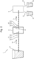
- the shrimp peeling apparatus 1 shown in Fig. 2 , comprises the shown stock 2, with an amount of shrimp 30 loaded therein, the shown positioning apparatus 3 accoding to the invention, and the shown peeling apparatus 4.
- Reference numeral 51 indicates a first singulated row of shrimp 30.
- the shrimp from this first singulated row 51 are coming from the stock 2, and they are supplied in the shown direction 70 to the positioning apparatus.
- these shrimp 30 have not yet been positioned in the abovementioned predetermined orientation. The fact is, that this positioning only takes place in the positioning apparatus 3.
- Reference numeral 52 indicates the abovementioned singulated output row of shrimp 30, which have been positioned in the predetermined orientation.
- This singulated output row 52 moves via the shown output conveying means 8 of the positioning apparatus 3 in the shown direction 71 towards the peeling apparatus 4.
- the shrimp 30 are peeled by the peeling apparatus 4, whereafter the peeled shrimp via the shown arrow 72 are supplied to the shown first holder 5, while the released peeling residue via the shown arrow 73 is supplied to the shown second holder 6.
- Figs. 3 through 8C in which the positioning apparatus 3 is shown in more detail.
- the sliding chute assembly and the output conveying means of the positioning apparatus 3 are indicated by the reference numerals 7 and 8, respectively.
- the endless conveyor belt and the multiple sliding chutes for shrimp, being held by the endless conveyor belt, are indicated by the reference numerals 10 and 9, respectively.
- Fig 3 shows that the endless conveyor belt 10 of the sliding chute assembly 7 is wound about two rolls 14, which turn in the shown direction 74.
- Figs. 4A and 4B show the shrimp entry 91, the shrimp exit 92, and the inclination trajectory 93 of each sliding chute 9.
- Figs. 4A and 4B also show an example of the valve, mentioned in the introduction, for temporarily stopping a shrimp, which is sliding along the inclination trajectory 93.
- This valve indicated by reference numeral 16, comprises two blades 11 and 12, which in a mutually fixed position are reciprocally rotatable around an axis 15 according to the shown double arrow 75.
- the gravity acting on the blade 11 takes care that the blade 12 is pressed against the sliding chute 9 in such manner that the blade 12 stops the shrimp 30.
- Fig. 4A especially the gravity acting on the blade 11 takes care that the blade 12 is pressed against the sliding chute 9 in such manner that the blade 12 stops the shrimp 30.
- Fig. 4A especially the gravity acting on the blade 11 takes care that the blade 12 is pressed against the sliding chute 9 in such manner that the blade 12 stops the shrimp 30.
- Fig. 4A especially the gravity acting on
- a valve guiding element 18 keeps the blade 11 pressed upwards, whereby the blade 12 is loose from the sliding chute 9 in such manner that the shrimp 30 is not stopped anymore by the blade 12.
- the shrimp slides further downward in the sliding direction 76.
- a shrimp sliding along the sliding chute 9 has the tendency to downwardly slide with its back facing forwards. This tendency may still be enhanced by blowing means creating a slight upwardly directed blowing flow along the sliding chute 9, which in the Figs. 4A and 4B is shown in the form of the first blowing means 61 with corresponding first blowing flow 81.
- Fig. 5 shows that the output conveying means 8 comprise an endless output conveying belt 20, which is wound about two rolls 17 turning in the shown direction 77.
- the abovementioned separation walls are attached to this output conveying belt 20. These separation walls, which are extending transversely to the output conveying belt 20, are each indicated by the reference numeral 21.
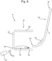
- the output conveying means 8 further comprise a fixedly arranged horizontal slippery bottom 40, as well as a fixedly arranged vertical slippery wall 41, see for example also Fig. 6 .
- the abovementioned shrimp dispensing trajectory 53 of the endless conveyor belt 10 of the sliding chute assembly 7 and the shrimp receiving trajectory of the output conveying means 8 are indicated by the reference numerals 53 and 54, respectively.
- the guiding element 18, which presses the blade 11 of the valve 16 upwards is fixedly arranged in an area which is extending from just before the shrimp dispensing trajectory 53 till somewhere within the shrimp dispensing trajectory 53.
- the valve 16 of each sliding chute 9, moving together with the conveyor belt 10 is opened just before the dispensing trajectory 53, whereafter the shrimp 30 in the shrimp dispensing trajectory 53 can slide downwards in the direction of the arrow 76.
- the valve 16 closes again, in order to only open again in a next turning cycle of the conveyor belt 10, just before the shrimp dispensing trajectory 53.
- Fig. 6 it is shown that in the shrimp transfering trajectory, formed by mutual overlapping of the shrimp dispensing trajectory 53 and the shrimp receiving trajectory 54, of the positioning apparatus 3 the shrimp exits 92 of the sliding chutes 9 discharge into the shrimp receiving trajectory 54 of the output conveying means 8.
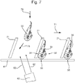
- the shrimp 30 can arrive at the slippery bottom 40, and be pushed forward, by a separation wall 21 concerned, over the slippery bottom 40 and along the slippery wall 41 in the direction of the arrow 71, also see Figs. 5 and 7 .
- Figs. 3 , 6 and 7 further show second blowing means 62 with a corresponding second blowing flow 82, which promotes that a shrimp 30, sliding out of the sliding chute 9, after bumping against the slippery wall 41, remains nicely lying with its back 35 against the slippery wall 41.
- the second blowing flow 82 is somewhat obliquely directed towards the separation wall 21, whereby the shrimp travels along a somewhat bent movement path, indicated by the arrow 78 in Fig. 7 .
- Figs. 5 , 8A, 8B and 8C further show third blowing means 63 with a corresponding third blowing flow 83, which is upwardly directed through a blowing opening 43 in the slippery bottom 40.
- This blowing opening 43 is situated, in the sense of the movement direction 71, somewhat farther than the shrimp receiving trajectory 54 of the output conveying means 8.
- This third blowing means 63 with corresponding third blowing flow 83 are forming the abovementioned turn-around blowing means with corresponding turn-around blowing flow.
- Figs. 8A, 8B and 8C it is assumed that it is the intention that all shrimp 30 in the singulated output row 52 will have to lie with their first shrimp longitudinal side 31 against the separation wall 21 concerned.
- the (continuous) turn-around blowing flow 83 takes care that a shrimp 30, which lies with its second shrimp longitudinal side 32 against the separation wall 21 concerned, as shown in Fig. 8A , will be automatically turned-around. If the turn-around blowing flow 83 for a certain shrimp type has been adjusted to be neither too strong nor too weak, the turn-around blowing flow 83 will cause the shrimp 30 to roll over its first shrimp longitudinal side 31, as shown in Fig. 8B , whereafter the shrimp will end up in the desired orientation as shown in Fig. 8C .
- Figs. 2 , 3 and 5 a brief summary is given of the trajectory followed by the shrimp 30 in the shrimp peeling apparatus 1.
- Fig. 2 it is seen that the shrimp 30 from the first singulated row 51 are supplied to the positioning apparatus 3 in the shown direction 70.
- the supply location where this supplying takes place is seen in Fig. 3 , where the arrow 70 points to the supply location of a shrimp 30 to a shrimp entry 91 of a sliding chute 9, which at that moment is located there.
- the movement speed of the first singulated row 51 with the mutual distances between the shrimp 30 from the first singulated row 51 are tuned in such manner to the rotation speed of the conveyor belt 10 and to the mutual distances between the sliding chutes 9, that successive shrimp 30 from the first singulated row 51 are supplied at said supply location one after the other to sliding chutes 9 of the sliding chute assembly 7, which sliding chutes 9 are successiveively passing by there.
- the valve 16 is in the closed condition as shown in Fig. 4A .
- the valve 16 transfers into its open condition as shown in Fig. 4B , as a consequence of the valve guiding element 18 being present there.
- the reference numeral 16 is shown twice to indicate the final two locations before the shrimp dispensing trajectory 53 where a valve 16 concerned still is in its closed condition. Somewhat later a valve 16 concerned thus transfers into its open condition.
- Figs. 3 and 5 it can be seen that the shrimp 30 in the shrimp transfering trajectory of the positioning apparatus 3, which shrimp transfering trajectory is formed by the shrimp dispensing trajectory 53 and the shrimp receiving trajectory 54, gradually transfer to the singulated output row 52.
- this singulated output row 52 the shrimp 30 are all lying with their backs 35 against the slippery wall 41.
- a first degree of positioning of the shrimp is accomplished.
- the rotation speed of the conveyor belt 10 with the mutual distances between the sliding chutes 9 are tuned in such manner to the movement speed of the output conveyor belt 20 with the mutual distances between adjacent separation walls 21, that, in-between each pair of adjacent separation walls 21, each time there is supplied one of the shrimp 30 dispensed from the sliding chutes 9.
- the movement speed of the conveyor belt 10 may for example be equal to the movement speed of the output conveyor belt 20, while the distances between all sliding chutes 9, lying next to one another, are equidistant and equal to the distances between all separation walls 21 lying next to one another, being equidistant as well.
- the shrimp exits 92 of a plurality of adjacent sliding chutes 9 can move along with the interspaces between separation walls 21 lying next to one aonther, while those co-moving shrimp exits 92 in the shrimp transfering trajectory during their movements remain discharging into those interspaces.
- the movement speed of the first singulated row 51 in the direction 70 can be relatively high and the mutual distance between the shrimp 30 in the first singulated row 51 can be relatively small, while also the movement speed of the singulated output row 52 in the direction 71 can be relatively high and the mutual distance between the shrimp 30 in the singulated output row 52 can be relatively small.
- the throughput capacity is considerably increased in the positioning of shrimp based on downwards sliding of shrimp.
- the singulated output row 52 at the end of the shown output conveying means 8 can, if desired, simply be transfered to a further output conveying means.
Landscapes
- Engineering & Computer Science (AREA)
- Life Sciences & Earth Sciences (AREA)
- Wood Science & Technology (AREA)
- Zoology (AREA)
- Food Science & Technology (AREA)
- Mechanical Engineering (AREA)
- Processing Of Meat And Fish (AREA)
- Meat, Egg Or Seafood Products (AREA)
Priority Applications (1)
| Application Number | Priority Date | Filing Date | Title |
|---|---|---|---|
| PL15732476T PL3148340T3 (pl) | 2014-05-28 | 2015-05-27 | Urządzenie i sposób dla pozycjonowania krewetek |
Applications Claiming Priority (2)
| Application Number | Priority Date | Filing Date | Title |
|---|---|---|---|
| NL2012902A NL2012902B1 (nl) | 2014-05-28 | 2014-05-28 | Inrichting en werkwijze voor het positioneren van garnalen. |
| PCT/NL2015/050381 WO2015183089A1 (en) | 2014-05-28 | 2015-05-27 | Apparatus and method for positioning of shrimp |
Publications (2)
| Publication Number | Publication Date |
|---|---|
| EP3148340A1 EP3148340A1 (en) | 2017-04-05 |
| EP3148340B1 true EP3148340B1 (en) | 2018-04-18 |
Family
ID=51691104
Family Applications (1)
| Application Number | Title | Priority Date | Filing Date |
|---|---|---|---|
| EP15732476.5A Active EP3148340B1 (en) | 2014-05-28 | 2015-05-27 | Apparatus and method for positioning of shrimp |
Country Status (6)
| Country | Link |
|---|---|
| EP (1) | EP3148340B1 (da) |
| CA (1) | CA2949781C (da) |
| DK (2) | DK3148340T3 (da) |
| NL (1) | NL2012902B1 (da) |
| PL (1) | PL3148340T3 (da) |
| WO (1) | WO2015183089A1 (da) |
Families Citing this family (4)
| Publication number | Priority date | Publication date | Assignee | Title |
|---|---|---|---|---|
| CN107186290B (zh) * | 2017-06-27 | 2023-05-30 | 厦门鑫朋工贸有限公司 | 一种给管接头攻牙的自动生产线 |
| CN107712016B (zh) * | 2017-11-07 | 2020-01-03 | 浙江国际海运职业技术学院 | 摇摆式虾类清洗装置 |
| CN110921219B (zh) * | 2019-11-20 | 2021-05-07 | 孟弢 | 一种小龙虾排序设备 |
| WO2021158894A1 (en) | 2020-02-07 | 2021-08-12 | Nova-Tech Engineering, Llc | Shrimp processing system, processing apparatus and methods |
Citations (2)
| Publication number | Priority date | Publication date | Assignee | Title |
|---|---|---|---|---|
| EP0743010A1 (en) * | 1995-04-28 | 1996-11-20 | Albert Kant | Method and apparatus for peeling shrimp |
| EP2471373A1 (en) * | 2010-12-30 | 2012-07-04 | Heiploeg B.V. | Device for the positioning of shrimps |
Family Cites Families (1)
| Publication number | Priority date | Publication date | Assignee | Title |
|---|---|---|---|---|
| NL2002413C2 (en) | 2009-01-13 | 2010-07-14 | Albert Kant | Apparatus and method for mechanized peeling of shrimp. |
-
2014
- 2014-05-28 NL NL2012902A patent/NL2012902B1/nl not_active IP Right Cessation
-
2015
- 2015-05-27 EP EP15732476.5A patent/EP3148340B1/en active Active
- 2015-05-27 WO PCT/NL2015/050381 patent/WO2015183089A1/en not_active Ceased
- 2015-05-27 DK DK15732476.5T patent/DK3148340T3/da active
- 2015-05-27 PL PL15732476T patent/PL3148340T3/pl unknown
- 2015-05-27 CA CA2949781A patent/CA2949781C/en active Active
-
2016
- 2016-12-27 DK DKPA201600800A patent/DK179114B1/en active
Patent Citations (2)
| Publication number | Priority date | Publication date | Assignee | Title |
|---|---|---|---|---|
| EP0743010A1 (en) * | 1995-04-28 | 1996-11-20 | Albert Kant | Method and apparatus for peeling shrimp |
| EP2471373A1 (en) * | 2010-12-30 | 2012-07-04 | Heiploeg B.V. | Device for the positioning of shrimps |
Also Published As
| Publication number | Publication date |
|---|---|
| CA2949781A1 (en) | 2015-12-03 |
| DK179114B1 (en) | 2017-11-06 |
| NL2012902B1 (nl) | 2016-06-08 |
| WO2015183089A1 (en) | 2015-12-03 |
| PL3148340T3 (pl) | 2018-09-28 |
| DK201600800A1 (en) | 2017-01-09 |
| CA2949781C (en) | 2022-04-19 |
| EP3148340A1 (en) | 2017-04-05 |
| DK3148340T3 (da) | 2018-06-06 |
Similar Documents
| Publication | Publication Date | Title |
|---|---|---|
| EP3148340B1 (en) | Apparatus and method for positioning of shrimp | |
| CN114867669B (zh) | 用于运输和分离活的家禽禽鸟的组合件 | |
| US4091915A (en) | Machine for packaging dispensing spoons and method | |
| US10455856B2 (en) | Method and machine for pitting and re-pitting fruit halves | |
| US11230437B2 (en) | Feeding device for feeding products onto a conveyor belt | |
| US10144545B2 (en) | Device and method for feeding pouches to a carousel | |
| EP3331384B1 (en) | Automated strawberry orienting and capping machine | |
| KR101162465B1 (ko) | 양파껍질 탈피장치 | |
| US10053298B2 (en) | Egg orientation device | |
| US2908375A (en) | Vertical descent mating pan lemon feeder | |
| EP3148903B1 (en) | Distribution system for supplying irregularly shaped products such as pears to a singulating means, and transport system and method therefor | |
| EP4009814B1 (en) | Pear feeding method and apparatus for multi-lane processing | |
| JP6809683B2 (ja) | 園芸生産物を振り分けるための装置 | |
| US3265273A (en) | Machine for feeding and setting fasteners | |
| US3394805A (en) | Tapered agricultural product orienting and feeding apparatus and method | |
| US3561041A (en) | Fish handling method and apparatus | |
| US2375350A (en) | Fruit handling machine | |
| EP2019056A1 (en) | Device for conveying round objects | |
| JP2024532108A (ja) | 取扱設備、食品加工設備、及び食品の取り扱い方法 | |
| CN209914987U (zh) | 一种红枣去核开口装置 | |
| US2314484A (en) | Metering and aligning machine | |
| US4962699A (en) | Distributing apparatus | |
| US1030646A (en) | Machine for handling and cutting fish. | |
| US6471035B1 (en) | Multi-stage metal-forming machine tool | |
| WO1998047796A1 (en) | Dry shuffle feed for produce |
Legal Events
| Date | Code | Title | Description |
|---|---|---|---|
| PUAI | Public reference made under article 153(3) epc to a published international application that has entered the european phase |
Free format text: ORIGINAL CODE: 0009012 |
|
| 17P | Request for examination filed |
Effective date: 20161228 |
|
| AK | Designated contracting states |
Kind code of ref document: A1 Designated state(s): AL AT BE BG CH CY CZ DE DK EE ES FI FR GB GR HR HU IE IS IT LI LT LU LV MC MK MT NL NO PL PT RO RS SE SI SK SM TR |
|
| AX | Request for extension of the european patent |
Extension state: BA ME |
|
| DAV | Request for validation of the european patent (deleted) | ||
| DAX | Request for extension of the european patent (deleted) | ||
| 17Q | First examination report despatched |
Effective date: 20171030 |
|
| GRAP | Despatch of communication of intention to grant a patent |
Free format text: ORIGINAL CODE: EPIDOSNIGR1 |
|
| INTG | Intention to grant announced |
Effective date: 20180116 |
|
| GRAS | Grant fee paid |
Free format text: ORIGINAL CODE: EPIDOSNIGR3 |
|
| GRAA | (expected) grant |
Free format text: ORIGINAL CODE: 0009210 |
|
| AK | Designated contracting states |
Kind code of ref document: B1 Designated state(s): AL AT BE BG CH CY CZ DE DK EE ES FI FR GB GR HR HU IE IS IT LI LT LU LV MC MK MT NL NO PL PT RO RS SE SI SK SM TR |
|
| REG | Reference to a national code |
Ref country code: GB Ref legal event code: FG4D |
|
| REG | Reference to a national code |
Ref country code: CH Ref legal event code: EP |
|
| REG | Reference to a national code |
Ref country code: AT Ref legal event code: REF Ref document number: 989428 Country of ref document: AT Kind code of ref document: T Effective date: 20180515 |
|
| REG | Reference to a national code |
Ref country code: IE Ref legal event code: FG4D |
|
| REG | Reference to a national code |
Ref country code: DE Ref legal event code: R096 Ref document number: 602015010177 Country of ref document: DE |
|
| REG | Reference to a national code |
Ref country code: FR Ref legal event code: PLFP Year of fee payment: 4 |
|
| REG | Reference to a national code |
Ref country code: DK Ref legal event code: T3 Effective date: 20180531 |
|
| REG | Reference to a national code |
Ref country code: NL Ref legal event code: FP |
|
| PGFP | Annual fee paid to national office [announced via postgrant information from national office to epo] |
Ref country code: DK Payment date: 20180518 Year of fee payment: 4 |
|
| REG | Reference to a national code |
Ref country code: LT Ref legal event code: MG4D |
|
| PG25 | Lapsed in a contracting state [announced via postgrant information from national office to epo] |
Ref country code: FI Free format text: LAPSE BECAUSE OF FAILURE TO SUBMIT A TRANSLATION OF THE DESCRIPTION OR TO PAY THE FEE WITHIN THE PRESCRIBED TIME-LIMIT Effective date: 20180418 Ref country code: BG Free format text: LAPSE BECAUSE OF FAILURE TO SUBMIT A TRANSLATION OF THE DESCRIPTION OR TO PAY THE FEE WITHIN THE PRESCRIBED TIME-LIMIT Effective date: 20180718 Ref country code: AL Free format text: LAPSE BECAUSE OF FAILURE TO SUBMIT A TRANSLATION OF THE DESCRIPTION OR TO PAY THE FEE WITHIN THE PRESCRIBED TIME-LIMIT Effective date: 20180418 Ref country code: NO Free format text: LAPSE BECAUSE OF FAILURE TO SUBMIT A TRANSLATION OF THE DESCRIPTION OR TO PAY THE FEE WITHIN THE PRESCRIBED TIME-LIMIT Effective date: 20180718 Ref country code: ES Free format text: LAPSE BECAUSE OF FAILURE TO SUBMIT A TRANSLATION OF THE DESCRIPTION OR TO PAY THE FEE WITHIN THE PRESCRIBED TIME-LIMIT Effective date: 20180418 Ref country code: SE Free format text: LAPSE BECAUSE OF FAILURE TO SUBMIT A TRANSLATION OF THE DESCRIPTION OR TO PAY THE FEE WITHIN THE PRESCRIBED TIME-LIMIT Effective date: 20180418 Ref country code: LT Free format text: LAPSE BECAUSE OF FAILURE TO SUBMIT A TRANSLATION OF THE DESCRIPTION OR TO PAY THE FEE WITHIN THE PRESCRIBED TIME-LIMIT Effective date: 20180418 |
|
| PG25 | Lapsed in a contracting state [announced via postgrant information from national office to epo] |
Ref country code: HR Free format text: LAPSE BECAUSE OF FAILURE TO SUBMIT A TRANSLATION OF THE DESCRIPTION OR TO PAY THE FEE WITHIN THE PRESCRIBED TIME-LIMIT Effective date: 20180418 Ref country code: GR Free format text: LAPSE BECAUSE OF FAILURE TO SUBMIT A TRANSLATION OF THE DESCRIPTION OR TO PAY THE FEE WITHIN THE PRESCRIBED TIME-LIMIT Effective date: 20180719 Ref country code: LV Free format text: LAPSE BECAUSE OF FAILURE TO SUBMIT A TRANSLATION OF THE DESCRIPTION OR TO PAY THE FEE WITHIN THE PRESCRIBED TIME-LIMIT Effective date: 20180418 Ref country code: RS Free format text: LAPSE BECAUSE OF FAILURE TO SUBMIT A TRANSLATION OF THE DESCRIPTION OR TO PAY THE FEE WITHIN THE PRESCRIBED TIME-LIMIT Effective date: 20180418 |
|
| REG | Reference to a national code |
Ref country code: CH Ref legal event code: PL |
|
| REG | Reference to a national code |
Ref country code: AT Ref legal event code: MK05 Ref document number: 989428 Country of ref document: AT Kind code of ref document: T Effective date: 20180418 |
|
| REG | Reference to a national code |
Ref country code: DE Ref legal event code: R097 Ref document number: 602015010177 Country of ref document: DE |
|
| PG25 | Lapsed in a contracting state [announced via postgrant information from national office to epo] |
Ref country code: CZ Free format text: LAPSE BECAUSE OF FAILURE TO SUBMIT A TRANSLATION OF THE DESCRIPTION OR TO PAY THE FEE WITHIN THE PRESCRIBED TIME-LIMIT Effective date: 20180418 Ref country code: RO Free format text: LAPSE BECAUSE OF FAILURE TO SUBMIT A TRANSLATION OF THE DESCRIPTION OR TO PAY THE FEE WITHIN THE PRESCRIBED TIME-LIMIT Effective date: 20180418 Ref country code: SK Free format text: LAPSE BECAUSE OF FAILURE TO SUBMIT A TRANSLATION OF THE DESCRIPTION OR TO PAY THE FEE WITHIN THE PRESCRIBED TIME-LIMIT Effective date: 20180418 Ref country code: EE Free format text: LAPSE BECAUSE OF FAILURE TO SUBMIT A TRANSLATION OF THE DESCRIPTION OR TO PAY THE FEE WITHIN THE PRESCRIBED TIME-LIMIT Effective date: 20180418 Ref country code: MC Free format text: LAPSE BECAUSE OF FAILURE TO SUBMIT A TRANSLATION OF THE DESCRIPTION OR TO PAY THE FEE WITHIN THE PRESCRIBED TIME-LIMIT Effective date: 20180418 Ref country code: AT Free format text: LAPSE BECAUSE OF FAILURE TO SUBMIT A TRANSLATION OF THE DESCRIPTION OR TO PAY THE FEE WITHIN THE PRESCRIBED TIME-LIMIT Effective date: 20180418 |
|
| PLBE | No opposition filed within time limit |
Free format text: ORIGINAL CODE: 0009261 |
|
| STAA | Information on the status of an ep patent application or granted ep patent |
Free format text: STATUS: NO OPPOSITION FILED WITHIN TIME LIMIT |
|
| PG25 | Lapsed in a contracting state [announced via postgrant information from national office to epo] |
Ref country code: CH Free format text: LAPSE BECAUSE OF NON-PAYMENT OF DUE FEES Effective date: 20180531 Ref country code: LI Free format text: LAPSE BECAUSE OF NON-PAYMENT OF DUE FEES Effective date: 20180531 Ref country code: SM Free format text: LAPSE BECAUSE OF FAILURE TO SUBMIT A TRANSLATION OF THE DESCRIPTION OR TO PAY THE FEE WITHIN THE PRESCRIBED TIME-LIMIT Effective date: 20180418 Ref country code: IT Free format text: LAPSE BECAUSE OF FAILURE TO SUBMIT A TRANSLATION OF THE DESCRIPTION OR TO PAY THE FEE WITHIN THE PRESCRIBED TIME-LIMIT Effective date: 20180418 |
|
| 26N | No opposition filed |
Effective date: 20190121 |
|
| PG25 | Lapsed in a contracting state [announced via postgrant information from national office to epo] |
Ref country code: SI Free format text: LAPSE BECAUSE OF FAILURE TO SUBMIT A TRANSLATION OF THE DESCRIPTION OR TO PAY THE FEE WITHIN THE PRESCRIBED TIME-LIMIT Effective date: 20180418 |
|
| REG | Reference to a national code |
Ref country code: DK Ref legal event code: EBP Effective date: 20190531 |
|
| PG25 | Lapsed in a contracting state [announced via postgrant information from national office to epo] |
Ref country code: MT Free format text: LAPSE BECAUSE OF NON-PAYMENT OF DUE FEES Effective date: 20180527 |
|
| PG25 | Lapsed in a contracting state [announced via postgrant information from national office to epo] |
Ref country code: TR Free format text: LAPSE BECAUSE OF FAILURE TO SUBMIT A TRANSLATION OF THE DESCRIPTION OR TO PAY THE FEE WITHIN THE PRESCRIBED TIME-LIMIT Effective date: 20180418 |
|
| PG25 | Lapsed in a contracting state [announced via postgrant information from national office to epo] |
Ref country code: DK Free format text: LAPSE BECAUSE OF NON-PAYMENT OF DUE FEES Effective date: 20190531 |
|
| PG25 | Lapsed in a contracting state [announced via postgrant information from national office to epo] |
Ref country code: PT Free format text: LAPSE BECAUSE OF FAILURE TO SUBMIT A TRANSLATION OF THE DESCRIPTION OR TO PAY THE FEE WITHIN THE PRESCRIBED TIME-LIMIT Effective date: 20180418 |
|
| PG25 | Lapsed in a contracting state [announced via postgrant information from national office to epo] |
Ref country code: MK Free format text: LAPSE BECAUSE OF NON-PAYMENT OF DUE FEES Effective date: 20180418 Ref country code: HU Free format text: LAPSE BECAUSE OF FAILURE TO SUBMIT A TRANSLATION OF THE DESCRIPTION OR TO PAY THE FEE WITHIN THE PRESCRIBED TIME-LIMIT; INVALID AB INITIO Effective date: 20150527 Ref country code: CY Free format text: LAPSE BECAUSE OF FAILURE TO SUBMIT A TRANSLATION OF THE DESCRIPTION OR TO PAY THE FEE WITHIN THE PRESCRIBED TIME-LIMIT Effective date: 20180418 |
|
| PGFP | Annual fee paid to national office [announced via postgrant information from national office to epo] |
Ref country code: NL Payment date: 20250304 Year of fee payment: 11 |
|
| PGFP | Annual fee paid to national office [announced via postgrant information from national office to epo] |
Ref country code: PL Payment date: 20250428 Year of fee payment: 11 Ref country code: DE Payment date: 20250521 Year of fee payment: 11 |
|
| PGFP | Annual fee paid to national office [announced via postgrant information from national office to epo] |
Ref country code: IS Payment date: 20250512 Year of fee payment: 11 |
|
| PGFP | Annual fee paid to national office [announced via postgrant information from national office to epo] |
Ref country code: LU Payment date: 20250521 Year of fee payment: 11 Ref country code: BE Payment date: 20250521 Year of fee payment: 11 |
|
| PGFP | Annual fee paid to national office [announced via postgrant information from national office to epo] |
Ref country code: FR Payment date: 20250528 Year of fee payment: 11 |
|
| PGFP | Annual fee paid to national office [announced via postgrant information from national office to epo] |
Ref country code: IE Payment date: 20250521 Year of fee payment: 11 |
|
| PGFP | Annual fee paid to national office [announced via postgrant information from national office to epo] |
Ref country code: GB Payment date: 20260324 Year of fee payment: 12 |