EP3148441B1 - Contrôle du mouvement et de l'acquisition d'image d'un système à rayons x pour un rendu 3d/4d co-enregistré d'une anatomie cible - Google Patents
Contrôle du mouvement et de l'acquisition d'image d'un système à rayons x pour un rendu 3d/4d co-enregistré d'une anatomie cible Download PDFInfo
- Publication number
- EP3148441B1 EP3148441B1 EP15784754.2A EP15784754A EP3148441B1 EP 3148441 B1 EP3148441 B1 EP 3148441B1 EP 15784754 A EP15784754 A EP 15784754A EP 3148441 B1 EP3148441 B1 EP 3148441B1
- Authority
- EP
- European Patent Office
- Prior art keywords
- imager
- processor
- image
- medical device
- mps
- Prior art date
- Legal status (The legal status is an assumption and is not a legal conclusion. Google has not performed a legal analysis and makes no representation as to the accuracy of the status listed.)
- Active
Links
Images



Classifications
-
- A—HUMAN NECESSITIES
- A61—MEDICAL OR VETERINARY SCIENCE; HYGIENE
- A61B—DIAGNOSIS; SURGERY; IDENTIFICATION
- A61B6/00—Apparatus or devices for radiation diagnosis; Apparatus or devices for radiation diagnosis combined with radiation therapy equipment
- A61B6/12—Arrangements for detecting or locating foreign bodies
-
- A—HUMAN NECESSITIES
- A61—MEDICAL OR VETERINARY SCIENCE; HYGIENE
- A61B—DIAGNOSIS; SURGERY; IDENTIFICATION
- A61B34/00—Computer-aided surgery; Manipulators or robots specially adapted for use in surgery
- A61B34/20—Surgical navigation systems; Devices for tracking or guiding surgical instruments, e.g. for frameless stereotaxis
-
- A—HUMAN NECESSITIES
- A61—MEDICAL OR VETERINARY SCIENCE; HYGIENE
- A61B—DIAGNOSIS; SURGERY; IDENTIFICATION
- A61B6/00—Apparatus or devices for radiation diagnosis; Apparatus or devices for radiation diagnosis combined with radiation therapy equipment
- A61B6/06—Diaphragms
-
- A—HUMAN NECESSITIES
- A61—MEDICAL OR VETERINARY SCIENCE; HYGIENE
- A61B—DIAGNOSIS; SURGERY; IDENTIFICATION
- A61B6/00—Apparatus or devices for radiation diagnosis; Apparatus or devices for radiation diagnosis combined with radiation therapy equipment
- A61B6/44—Constructional features of apparatus for radiation diagnosis
- A61B6/4429—Constructional features of apparatus for radiation diagnosis related to the mounting of source units and detector units
- A61B6/4435—Constructional features of apparatus for radiation diagnosis related to the mounting of source units and detector units the source unit and the detector unit being coupled by a rigid structure
- A61B6/4441—Constructional features of apparatus for radiation diagnosis related to the mounting of source units and detector units the source unit and the detector unit being coupled by a rigid structure the rigid structure being a C-arm or U-arm
-
- A—HUMAN NECESSITIES
- A61—MEDICAL OR VETERINARY SCIENCE; HYGIENE
- A61B—DIAGNOSIS; SURGERY; IDENTIFICATION
- A61B6/00—Apparatus or devices for radiation diagnosis; Apparatus or devices for radiation diagnosis combined with radiation therapy equipment
- A61B6/48—Diagnostic techniques
- A61B6/481—Diagnostic techniques involving the use of contrast agents
-
- A—HUMAN NECESSITIES
- A61—MEDICAL OR VETERINARY SCIENCE; HYGIENE
- A61B—DIAGNOSIS; SURGERY; IDENTIFICATION
- A61B6/00—Apparatus or devices for radiation diagnosis; Apparatus or devices for radiation diagnosis combined with radiation therapy equipment
- A61B6/48—Diagnostic techniques
- A61B6/486—Diagnostic techniques involving generating temporal series of image data
- A61B6/487—Diagnostic techniques involving generating temporal series of image data involving fluoroscopy
-
- A—HUMAN NECESSITIES
- A61—MEDICAL OR VETERINARY SCIENCE; HYGIENE
- A61B—DIAGNOSIS; SURGERY; IDENTIFICATION
- A61B6/00—Apparatus or devices for radiation diagnosis; Apparatus or devices for radiation diagnosis combined with radiation therapy equipment
- A61B6/50—Apparatus or devices for radiation diagnosis; Apparatus or devices for radiation diagnosis combined with radiation therapy equipment specially adapted for specific body parts; specially adapted for specific clinical applications
- A61B6/504—Apparatus or devices for radiation diagnosis; Apparatus or devices for radiation diagnosis combined with radiation therapy equipment specially adapted for specific body parts; specially adapted for specific clinical applications for diagnosis of blood vessels, e.g. by angiography
-
- A—HUMAN NECESSITIES
- A61—MEDICAL OR VETERINARY SCIENCE; HYGIENE
- A61B—DIAGNOSIS; SURGERY; IDENTIFICATION
- A61B6/00—Apparatus or devices for radiation diagnosis; Apparatus or devices for radiation diagnosis combined with radiation therapy equipment
- A61B6/52—Devices using data or image processing specially adapted for radiation diagnosis
- A61B6/5205—Devices using data or image processing specially adapted for radiation diagnosis involving processing of raw data to produce diagnostic data
-
- A—HUMAN NECESSITIES
- A61—MEDICAL OR VETERINARY SCIENCE; HYGIENE
- A61B—DIAGNOSIS; SURGERY; IDENTIFICATION
- A61B6/00—Apparatus or devices for radiation diagnosis; Apparatus or devices for radiation diagnosis combined with radiation therapy equipment
- A61B6/52—Devices using data or image processing specially adapted for radiation diagnosis
- A61B6/5211—Devices using data or image processing specially adapted for radiation diagnosis involving processing of medical diagnostic data
- A61B6/5229—Devices using data or image processing specially adapted for radiation diagnosis involving processing of medical diagnostic data combining image data of a patient, e.g. combining a functional image with an anatomical image
-
- A—HUMAN NECESSITIES
- A61—MEDICAL OR VETERINARY SCIENCE; HYGIENE
- A61B—DIAGNOSIS; SURGERY; IDENTIFICATION
- A61B6/00—Apparatus or devices for radiation diagnosis; Apparatus or devices for radiation diagnosis combined with radiation therapy equipment
- A61B6/54—Control of apparatus or devices for radiation diagnosis
- A61B6/541—Control of apparatus or devices for radiation diagnosis involving acquisition triggered by a physiological signal
-
- A—HUMAN NECESSITIES
- A61—MEDICAL OR VETERINARY SCIENCE; HYGIENE
- A61B—DIAGNOSIS; SURGERY; IDENTIFICATION
- A61B6/00—Apparatus or devices for radiation diagnosis; Apparatus or devices for radiation diagnosis combined with radiation therapy equipment
- A61B6/54—Control of apparatus or devices for radiation diagnosis
- A61B6/542—Control of apparatus or devices for radiation diagnosis involving control of exposure
-
- A—HUMAN NECESSITIES
- A61—MEDICAL OR VETERINARY SCIENCE; HYGIENE
- A61B—DIAGNOSIS; SURGERY; IDENTIFICATION
- A61B6/00—Apparatus or devices for radiation diagnosis; Apparatus or devices for radiation diagnosis combined with radiation therapy equipment
- A61B6/54—Control of apparatus or devices for radiation diagnosis
- A61B6/547—Control of apparatus or devices for radiation diagnosis involving tracking of position of the device or parts of the device
-
- A—HUMAN NECESSITIES
- A61—MEDICAL OR VETERINARY SCIENCE; HYGIENE
- A61B—DIAGNOSIS; SURGERY; IDENTIFICATION
- A61B34/00—Computer-aided surgery; Manipulators or robots specially adapted for use in surgery
- A61B34/20—Surgical navigation systems; Devices for tracking or guiding surgical instruments, e.g. for frameless stereotaxis
- A61B2034/2046—Tracking techniques
- A61B2034/2051—Electromagnetic tracking systems
-
- A—HUMAN NECESSITIES
- A61—MEDICAL OR VETERINARY SCIENCE; HYGIENE
- A61B—DIAGNOSIS; SURGERY; IDENTIFICATION
- A61B5/00—Measuring for diagnostic purposes; Identification of persons
- A61B5/06—Devices, other than using radiation, for detecting or locating foreign bodies ; Determining position of diagnostic devices within or on the body of the patient
- A61B5/061—Determining position of a probe within the body employing means separate from the probe, e.g. sensing internal probe position employing impedance electrodes on the surface of the body
- A61B5/062—Determining position of a probe within the body employing means separate from the probe, e.g. sensing internal probe position employing impedance electrodes on the surface of the body using magnetic field
Definitions
- the disclosed technique relates to medical imaging methods and systems.
- the disclosed technique relates to methods and systems for creating an anatomical model for navigating devices during medical procedures.
- Rotational angiography is a medical imaging technique used to create a 3D model of an anatomical target using a plurality of two-dimensional images acquired with an image detector. Examples of rotational angiography systems include the DynaCT system made by Siemens AG and the Allura 3D Coronary Angiography by Philips Healthcare.
- WO 2006/116748 A1 relates to a system for navigating medical probes within anatomical organs by using a tracking subsystem configured for detecting the position of another medical device, wherein an imager positioning subsystem is configured for adjusting the field of view position based further on the other detected medical device position.
- EP 1 901 232 A2 relates to a vascular treatment device for navigating through an occluded blood vessel.
- the disclosed technique overcomes the disadvantages of the prior art by controlling the movement and image acquisition of a X-ray system in order to optimize the amount of radiation and contrast dye used in generating models for anatomical visualization and navigation of medical devices.
- the disclosed technique includes a method of optimizing x-ray and dye amounts used to create a 3D or 4D model of a target anatomy using the localization data provided by MediGuideTM Technology (e.g., patient reference sensors and/or magnetically tracked devices) to be used as co-registration information for navigating devices during medical procedures.
- MediGuideTM Technology e.g., patient reference sensors and/or magnetically tracked devices
- the optimization is made possible by i) using a known location and orientation of a magnetically tracked device and/or patient reference sensor in the heart and other methods to define the region of interest location, ii) using a real time ECG and/or data from other patient reference sensors to characterize the mechanical cardiac motion and the motion caused by respiration, and iii) controlling the mechanical movement of an x-ray system (e.g., table, C-arm, source-to-image distance, image rotation), the image acquisition parameters (e.g., frame rate, zoom, or x-ray properties), and the trigger for image acquisition and dye release (e.g., based on biological signals such as respiration, patient movement, and cardiac cycle).
- an x-ray system e.g., table, C-arm, source-to-image distance, image rotation
- the image acquisition parameters e.g., frame rate, zoom, or x-ray properties
- the trigger for image acquisition and dye release e.g., based on biological signals such as respiration, patient movement, and cardiac
- position refers to either the location or the orientation of the object, or both the location and orientation thereof.
- magnetic region of interest refers to a region of the body of the patient which has to be magnetically radiated by a magnetic field generator, in order for a medical positioning system (MPS) sensor to respond to the radiated magnetic field, and enable the MPS to determine the position of the tip of a medical device.
- MPS medical positioning system
- image detector refers to a device which produces an image of the visual region of interest.
- the image detector can be an image intensifier, flat detector (e.g., complementary metal-oxide semiconductor--CMOS), and the like.
- magnetic coordinate system herein below, refers to a three-dimensional coordinate system associated with the MPS.
- 3D optical coordinate system herein below, refers to a three-dimensional coordinate system associated with a three-dimensional object which is viewed by the image detector.
- 2D optical coordinate system herein below, refers to a two-dimensional coordinate system associated with the image detected by the image detector viewing the three-dimensional object.
- body region of interest refers to a region of the body of a patient on which a therapeutic operation is to be performed.
- visual region of interest herein below, refers to a region of the body of the patient which is to be imaged by the moving imager.
- image detector region of interest refers to different sizes of the detection region of the image detector. The image detector can detect the visual region of interest, either by utilizing the entire area of the image detector, or smaller areas thereof around the center of the image detector.
- image detector ROI refers to both an image intensifier and a flat detector.
- image rotation refers to rotation of an image acquired by the image detector, performed by an image processor.
- image flip refers to a mirror image of the acquired image performed about an axis on a plane of the acquired image, wherein this axis represents the rotation of the acquired image about another axis perpendicular to the plane of the acquired image, relative to a reference angle (i.e., after performing the image rotation). For example, if the acquired image is rotated 25 degrees clockwise and an axis defines this amount of rotation, then the image flip defines another image obtained by rotating the acquired image by 180 degrees about this axis. In case no image rotation is performed, an image flip is performed about a predetermined axis (e.g., a substantially vertical axis located on the plane of the acquired image).
- a predetermined axis e.g., a substantially vertical axis located on the plane of the acquired image.
- moving image detector refers to an image detector in which the image detector moves linearly along an axis substantially normal to the surface of the emitter, and relative to the emitter, in order to zoom-in and zoom-out.
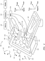
- FIG. 1 is a schematic illustration of a system, generally referenced 100, for displaying a representation a distal portion of a medical device 134 on a real-time image of the body of a patient 122, acquired by a moving imager 102, the position being determined according to the position and orientation of an MPS sensor 112 or distal portion of the medical device 134, the system being constructed and operative in accordance with an embodiment of the disclosed technique.
- System 100 which is described in commonly assigned U.S. Patent Application Publication No.
- 2008/0183071 includes a moving imager 102, a medical positioning system (MPS) 104, a database 106, a processor 108, a display 110, MPS sensors 112, 114 and 116, a plurality of magnetic field generators 118 (i.e., transmitters).
- MPS medical positioning system
- Moving imager 102 is a device which acquires an image (not shown) of a body region of interest 120 of the body of a patient 122 lying on an operation table 124.
- Moving imager 102 includes a moving assembly 126, a moving mechanism 128, an emitter 130, and an image detector 132.
- Moving imager 102 can operate based on X-rays, nuclear magnetic resonance, elementary particle emission, thermography, and the like. Moving imager 102 has at least one degree of freedom. In the example set forth in FIGS. 1 and 2 , moving imager 102 is a C-arm imager. Emitter 130 and image detector 132 are coupled with moving assembly 126, such that emitter 130 is located at one side of patient 122 and image detector 132 is located at the opposite side of patient 122. Emitter 130 and image detector 132 are located on a radiation axis (not shown), wherein the radiation axis crosses the body region of interest 120.
- the system can further include a user interface (e.g., a push button, joystick, foot pedal) coupled with the moving imager, to enable the physical staff to sequentially rotate the image acquired by the image detector, to flip the image at a given rotation angle, or set the ROI of the image detector.
- a user interface e.g., a push button, joystick, foot pedal
- the moving imager is constructed such that the image indexes forward or backward by a predetermined amount, at every activation of the push button. This index can be for example, five degrees, thus enabling the moving imager to perform a maximum of seventy two image rotations (i.e., 360 divided by 5). Since the moving imager can produce one image flip for each image rotation, a maximum of hundred and forty four images (i.e., 72 times 2) can be obtained from a single image acquired by the image detector.
- magnetic field generators 118 are firmly coupled with image detector 132 (in other embodiments, magnetic field generators 118 can be located elsewhere, such as under the operation table 124).
- MPS sensor 112 is located at a distal portion of a medical device 134.
- MPS sensor 114 is attached to a substantially stationary location of the body of patient 122.
- Medical device 134 is inserted to the body region of interest 120.
- MPS sensors 112 and 114, and magnetic field generators 118 are coupled with MPS 104.
- Each of MPS sensors 112 and 114 can be coupled with MPS 104 either by a conductor or by a wireless link.
- Processor 108 is coupled with moving imager 102, MPS 104, database 106 and with display 110.
- Moving imager 102 is associated with an X IMAGER , Y IMAGER , Z IMAGER coordinate system (i.e., a 3D optical coordinate system).
- MPS 104 is associated with an X MPS , Y MPS , Z MPS coordinate system (i.e., a magnetic coordinate system).
- the scaling of the 3D optical coordinate system is different than that of the magnetic coordinate system.
- Moving mechanism 128 is coupled with moving assembly 126, thereby enabling moving assembly 126 to rotate about the Y IMAGER axis. Moving mechanism 128 rotates moving assembly 126 in directions designated by arrows 136 and 138, thereby changing the orientation of the radiation axis on the X IMAGER -Z IMAGER plane and about the Y IMAGER axis.
- Moving mechanism 128 enables moving assembly 126 to rotate about the X IMAGER axis.
- Moving mechanism 128 rotates moving assembly 126 in directions designated by arrows 152 and 154, thereby changing the orientation of the radiation axis on the Z IMAGER -Y IMAGER plane and about the X IMAGER axis.
- Moving imager 102 can include another moving mechanism (not shown) coupled with moving imager 102, which can move moving imager 102 along the Y IMAGER axis in directions designated by arrows 144 and 146 (i.e., along the cranio-caudal axis of patient 122).
- Moving imager 102 can include a further moving mechanism (not shown) coupled with moving imager 102, which can move moving imager 102 along the X IMAGER axis in directions designated by arrows 148 and 150 (i.e., perpendicular to the cranio-caudal axis of patient 122).
- Moving mechanism 128 or another moving mechanism (not shown) coupled with operation table 124, can enable relative movements between moving imager 102 and the body region of interest 120 along the three axes of the 3D optical coordinate system, in addition to rotations in directions 136, 138, 152 and 154.
- Each of emitter 130 and image detector 132 is constructed and operative by methods known in the art.
- Image detector 132 can be provided with linear motion in directions toward and away from emitter 130, for varying the focal length of the image (i.e., in order to zoom-in and zoom-out). This zoom operation is herein below referred to as "physical zoom.”
- system 100 further includes a detector moving mechanism (not shown) coupled with image detector 132, in order to impart this linear motion to image detector 132.
- the detector moving mechanism can be either motorized or manual.
- the term "physical zoom” herein below, applies to an image detector which introduces distortions in an image acquired thereby (e.g., an image intensifier), as well as an image detector which introduces substantially no distortions (e.g., a flat detector).
- MPS sensor 116 i.e., image detector MPS sensor
- image detector MPS sensor can be firmly coupled with image detector 132 and coupled with MPS 104, in order to detect the position of image detector 132 along an axis (not shown) substantially normal to the surface of emitter 130, in the magnetic coordinate system.
- image detector 132 can include a position detector (not shown) coupled with processor 108, to inform processor 108 of the current position of moving imager 102 relative to emitter 130.
- This position detector can be of a type known in the art, such as optic, sonic, electromagnetic, electric, mechanical, and the like.
- processor 108 can determine the current position of moving imager 102 according to the output of the position detector, and MPS sensor 116 can be eliminated from system 100.
- image detector 132 is substantially stationary relative to emitter 130 during the real-time operation of system 100.
- the physical zoom is performed by moving moving-assembly 126 relative to body region of interest 120, or by moving operation table 124.
- MPS sensor 116 can be eliminated from system 100.
- processor 108 can determine the physical zoom according to an input from the physical staff via the user interface. In this case too, MPS sensor 116 can be eliminated.
- moving imager 102 can perform a zoom operation which depends on an image detector ROI setting.
- an image processor (not shown) associated with moving imager 102, produces zoomed images of the acquired images, by employing different image detector ROI settings, while preserving the original number of pixels and the original dimensions of each of the acquired images.
- the physical zoom setting of image detector 132 is a substantially continuous function (i.e., the physical zoom can be set at any non-discrete value within a given range).
- the image detector ROI can be set either at one of a plurality of discrete values (i.e., discontinuous), or non-discrete values (i.e., continuous).
- Magnetic field generators 118 are firmly coupled with image detector 132, in such a manner that magnetic field generators 118 do not physically interfere with radiations generated by image detector 132, and thus emitter 130 can direct a radiation at a field of view 140 toward the body region of interest 120, to be detected by image detector 132. In this manner, emitter 130 radiates a visual region of interest (not shown) of the body of patient 122.
- Image detector 132 produces an image output respective of the image of the body region of interest 120 in the 3D optical coordinate system. Image detector 132 sends the image output to processor 108 for display 110 to display the body region of interest 120. The location of MPS sensor 112 can be shown in the display.
- Magnetic field generators 118 produce a magnetic field 142 toward the body region of interest 120, thereby magnetically radiating a magnetic region of interest (not shown) of the body of patient 122. Since magnetic field generators 118 are firmly coupled with image detector 132, the field of view 140 is included within magnetic field 142, no matter what the position of image detector 132. Alternatively, magnetic field 142 is included within field of view 140. In any case, body region of interest 120 is an intersection of field of view 140 and magnetic field 142.
- MPS 104 determines the position of the distal portion of medical device 134 (i.e., performs position measurements) according to the output of MPS sensor 112.
- the visual region of interest substantially coincides with the magnetic region of interest
- MPS sensor 112 responds to magnetic field 142 substantially at all times during the movements of moving imager 102. It is desirable to determine the position of the distal portion of medical device 134, while medical device 134 is inserted into any portion of the body of patient 122 and while moving imager 102 is imaging that same portion of the body of patient 122. Since magnetic field generators 118 are firmly coupled with moving imager 102 and move with it at all times, system 100 provides this capability. This is true for any portion of the body of patient 122 which moving imager 102 can move toward, in order to detect an image thereof.
- magnetic field generators 118 are firmly coupled with moving imager 102, the 3D optical coordinate system and the magnetic coordinate system are firmly associated therewith and aligned together. Thus, when moving imager 102 moves relative to the body region of interest 120, magnetic field generators 118 move together with moving imager 102.
- the 3D optical coordinate system and the magnetic coordinate system are rigidly coupled. Therefore, it is not necessary for processor 108 to perform on-line computations for correlating the position measurements acquired by MPS 104 in the magnetic coordinate system, with the 3D optical coordinate system.
- the position of MPS sensor 112 relative to the image of the body region of interest 120 detected by moving imager 102 can be determined without performing any real-time computations, such as transforming the coordinates according to a transformation model (i.e., transformation matrix), and the like.
- a transformation model i.e., transformation matrix
- the transformation matrix for transforming a certain point in the magnetic coordinate system to a corresponding point in the 3D optical coordinate system is a unity matrix.
- magnetic field generators 118 are located substantially close to that portion of the body of patient 122, which is currently being treated and imaged by moving imager 102. Thus, it is possible to use magnetic field generators which are substantially small in size and which consume substantially low electric power. This is true for any portion of the body of patient 122 which moving imager 102 can move toward, in order to detect an image thereof. This arrangement increases the sensitivity of MPS 104 to the movements of MPS sensor 112 within the body of patient 122, and reduces the cost, volume and weight of magnetic field generators 118.
- magnetic field generators 118 provides the physical staff (not shown) a substantially clear view of body region of interest 120, and allows the physical staff a substantially easy reach to body region of interest 120. Since magnetic field generators 118 are firmly coupled with moving imager 102, any interference (e.g., magnetic, electric, electromagnetic) between MPS 104 and moving imager 102 can be identified beforehand, and compensated for during the operation of system 100.
- any interference e.g., magnetic, electric, electromagnetic
- the system can include MPS sensors, in addition to MPS sensor 112.
- the magnetic field generators can be part of a transmitter assembly, which includes the magnetic field generators, a plurality of mountings for each magnetic field generator, and a housing to enclose the transmitter assembly components.
- the transmitter assembly can be for example, in an annular shape which encompasses image detector 132.
- MPS 104 determines the viewing position value of image detector 132, according to an output of MPS sensor 114 (i.e., patient body MPS sensor), in the magnetic coordinate system, relative to the position of the body of patient 122.
- processor 108 can compensate for the movements of patient 122 and of moving imager 102 during the medical operation on patient 122, according to an output of MPS 104, while processor 108 processes the images which image detector 132 acquires from body region of interest 120.
- moving imager 102 is motorized, and can provide the position thereof to processor 108, directly, it is not necessary for processor 108 to receive data from MPS 104 respective of the position of MPS sensor 114, for determining the position of image detector 132. However, MPS sensor 114 is still necessary to enable MPS 104 to determine the position of the body of patient 122.
- processor 108 determines MPS data from MPS 104.
- the MPS data includes the position and/or orientation of the distal portion of medical device 134.
- the processor 108 determines such MPS data according to the output of MPS sensor 112, which can be positioned in a known anatomical location (e.g., coronary sinus) within body region of interest 120 using MPS 104.
- the processor 108 uses the MPS data, in conjunction with known anatomical and/or physiological information, to control the position of moving imager 102.
- processor 108 can control movement of moving mechanism 128 or another moving mechanism (not shown), moving assembly 126, image detector 132, emitter 130, or operation table 124, so as to position the moving imager 102 at prescribed angles or orientations based on the position and orientation of the medical device or anatomical target area as detected by MPS sensor 112. Such prescribed angles or orientations can be determined by processor 108 based on a look-up table stored in memory 106. For example, a look-up table correlating a specified position of the distal portion of medical device 134 or MPS sensor 112 with a specified angle/orientation of moving imager 102 can be used by processor 108 to determine the optimal angle/orientation of moving imager 102.
- the look-up table can also include the associated anatomical location of MPS sensor 112, as well as the physiological state of the patient 122 (e.g., which phase of the cardiac and/or respiratory cycle the patient is in, as determined by patient reference sensors).
- the optimal angle/orientation of moving imager 102 can be that which best avoids the foreshortening effect of an organ in the x-ray image, thereby diminishing the number of x-ray frames required to adequately visualize the organ.
- FIG. 2 a zoomed-in view of the position and orientation of moving imager 102 is shown with respect to the distal portion of medical device 134 and MPS sensor 112.
- the distal portion of medical device 134 and MPS sensor 112 are located within a body of a patient, no patient is shown in FIG. 2 in order to more clearly illustrate the spatial relationship between moving imager 102 and the distal portion of medical device 134/MPS sensor 112.
- moving imager 102 is positioned so that axis 160, between emitter 130 and image detector 132, is perpendicular to axis 162, the longitudinal axis of the distal portion of medical device 134 as defined by the orientation of MPS sensor 112.
- Moving imager 102 is also positioned so that emitter 130 and image detector 132 are centered on axis 162. It can be assumed that the coronary vessel in which the distal portion of medical device 134 resides is coaxial with the device and shares longitudinal axis 162. Thus, by positioning moving imager 102 so that axis 160 is perpendicular to axis 162, and by centering moving imager 102 on axis 162, a focused image of a substantial portion of a coronary vessel can be taken with minimal fluoroscopy and without the need for many additional frames.
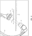
- the alignment of image detector 132 and emitter 130 is shown, along with ROI 170, represented here as a cylinder, in relation to MPS sensor 112.
- ROI 170 represented here as a cylinder
- the base of the cylinder is concentric with MPS sensor 112 and aligned with its axis 162 (shown in FIG. 2 ).
- the ROI 170 can be defined as a sphere, a cone, or another shape in place of a cylinder. It should be noted that the x-ray beam emitted from emitter 130 is wider than the volume of the volume of ROI 170.
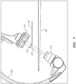
- the alignment of image detector 132 and emitter 130 is again shown with ROI 170.
- the imager 120 has been rotated 30 degrees caudally in order to minimize the area (e.g., on the body of the patient 122) that is exposed to the x-ray beam.
- the ROI 170 remains centered on and perpendicular to axis 160 (shown in FIG. 2 ) between the emitter 130 and the image detector 132.
- a 3D model of ROI 170 can be produced using images taken from at least two different angles/orientations of moving imager 102 (e.g., two angles separated by about 30-45 degrees).
- a 4D model (e.g., real time) of ROI 170 can be produced using images taken from at least three different angles/orientations of moving imager 102.
- the x-ray beam can be collimated to narrow in on ROI 170 and further limit fluoroscopic exposure.
- An emitter collimator (not shown) can be adjusted to fit the size of ROI 170, including movements due to the cardiac or respiration cycles, for example.
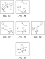
- FIG. 8A is a zoomed-in view of a three-dimensional schematic representation of a branching blood vessel 111, such as a coronary vein, is shown in conjunction with the positions of the MPS sensors 112 and 114.
- FIGS. 8B-8F are schematic illustrations of simulated x-ray images of the vessel 111 and position sensors 112 and 114 taken from various different angles/orientations of the imager 102. Each simulated x-ray image shows the vessel 111 and the positions of the MPS sensors 112 and 114 as viewed from a specified position of the imager 102.
- FIG. 8D is a simulated anterior-posterior x-ray image, defining a starting position of the imager 102.
- FIG. 8B shows a simulated x-ray image taken when the imager 102 has been rotated 20 degrees caudally relative to the starting position.
- FIG. 8C shows a simulated x-ray image taken when the imager 102 has been rotated 45 degrees to the left relative to the starting position.
- FIG. 8E shows a simulated x-ray image taken when the imager 102 has been rotated 45 degrees to the right relative to the starting position.
- FIG. 8F shows a simulated x-ray image taken when the imager 102 has been rotated 20 degrees cranially relative to its starting position.
- processor 108 can use MPS data to control the activation or deactivation timing of emitter 130 and/or a contrast dye injector device 115.
- Contrast dye injector device 115 can be coupled directly or indirectly to processor 108 and/or moving imager 102. Contrast dye injector device 115 can be located at the distal portion of medical device 134, as shown in FIG. 1 .
- a contrast dye injector device 115A can be located within a catheter 135 with MPS sensors 112A and 112B attached to the distal end 137.
- MPS sensors 112A and 112B are magnetic coils.
- Contrast dye injector device 115 or 115A can be coupled to a dye storage unit 119, which in turn can be coupled to processor 108.
- look-up tables correlating a position of MPS sensor 112 with an angle of moving imager 102 look-up tables correlating a specified position of MPS sensor 112 (or 112A or 112B) with an activation/deactivation timing signal for emitter 130 can be stored in memory 106 and used by processor 108 to create optimally-timed x-ray acquisition, thereby limiting fluoroscopic exposure.
- look-up tables correlating a specified position of MPS sensor 112 (or 112A or 112B) with an activation/deactivation timing signal for the release of dye from contrast dye injector device 115 or 115A can be stored in memory 106 and used by processor 108 to create optimally-timed x-ray acquisition, thereby limiting fluoroscopic exposure.
- input from a patient reference sensor such as MPS sensor 114, for example, can be used by processor 108 to control positioning, orientation, and/or activation of moving imager 102.
- Examples of input from patient reference sensors include data regarding the patient's cardiac or respiratory cycle.
- moving imager 102 can be positioned so that the source-to-image distance (SID) between the emitter 130 and the MPS sensor 112 is predefined based on the MPS data.
- SID source-to-image distance
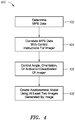
- FIG. 4 is a schematic illustration of a method 400 for producing an anatomical model by controlling the position, orientation, and image acquisition of an x-ray imaging system, the system being constructed and operative in accordance with an embodiment of the disclosed technique.
- MPS data is determined.
- At least one MPS sensor image of at least one MPS sensor (e.g., MPS sensor 112 located at the distal portion of medical device 134) is acquired by a moving imager, as described above with respect to FIG. 1 .
- the output of the MPS sensor determines the MPS data, which is the position and/or orientation of a medical device coupled to the MPS sensor.
- the MPS data is correlated with control instructions for the moving imager.
- This step can be performed by a processor using look-up tables stored in a memory.
- look-up tables can correlate a specified position of a medical device or a MPS sensor with i) a specified angle of the moving imager, ii) a specified activation or deactivation timing signal for the moving imager, or iii) a specified activation or deactivation timing signal for a dye injector device (e.g., contrast dye injector device 115 or 115A shown in FIGS. 1 and 3 , respectively).
- a dye injector device e.g., contrast dye injector device 115 or 115A shown in FIGS. 1 and 3 , respectively.
- the look-up tables can also include the associated anatomical location of the MPS sensor, as well as the physiological state of the patient (e.g., which phase of the cardiac and/or respiratory cycle the patient is in, as determined by patient reference sensors). These correlations are used to determine control instructions that the processor provides to the moving imager.
- the angle, orientation or activation/deactivation status of the moving imager are controlled by the processor based on the information derived from the look-up tables. For example, based on the specified position of an MPS sensor, the moving imager may be positioned at a prescribed angle or orientation. Moreover, the moving imager, or an emitter portion of the moving imager, may be activated or deactivated based on the MPS data. Finally, a dye injector device may be activated or deactivated based on the MPS data. In addition to MPS data, data from one or more patient reference sensors can be used to control the angle, orientation or activation/deactivation status of the moving imager.
- an anatomical model of the target area can be created using at least two images generated by the moving imager.
- at least two 2D images generated by the moving imager can be used to create a 3D anatomical model
- at least three 2D images generated by the moving imager can be used to create a 4D (e.g., real time) anatomical model.
- the method 400 may include a co-registering step (not shown) in which the MPS coordinates of the MPS sensor are co-registered with imaging coordinates of the MPS sensor. This step may be omitted when magnetic field generators 118 are firmly coupled with moving imager 102, and the 3D optical coordinate system and the magnetic coordinate system are firmly associated therewith and aligned together, as described above with respect to FIG. 1 .
- the anatomical model produced according to method 400 can be displayed on display 110, shown in FIG. 1 .
- the location of the MPS sensor e.g., MPS sensor 112 shown in FIG. 1
- the MPS sensor can be shown in the displayed anatomical model.
- Method 400 may further include an optional step (not shown) in which a user can control moving imager 102 via a user interface.
- joinder references are to be construed broadly and can include intermediate members between a connection of elements and relative movement between elements. As such, joinder references do not necessarily infer that two elements are directly connected and in fixed relationship to each other. It is intended that all matter contained in the above description or shown in the accompanying drawings shall be interpreted as illustrative only and not limiting. Changes in detail or structure can be made without departing from the spirit of the disclosure.
- proximal and distal have been used throughout the specification with reference to a clinician manipulating one end of an instrument used to treat a patient.
- proximal refers to the portion of the instrument closest to the clinician and the term “distal” refers to the portion located furthest from the clinician.
- distal refers to the portion located furthest from the clinician.
Landscapes
- Health & Medical Sciences (AREA)
- Life Sciences & Earth Sciences (AREA)
- Engineering & Computer Science (AREA)
- Medical Informatics (AREA)
- Surgery (AREA)
- Heart & Thoracic Surgery (AREA)
- General Health & Medical Sciences (AREA)
- Nuclear Medicine, Radiotherapy & Molecular Imaging (AREA)
- Veterinary Medicine (AREA)
- Public Health (AREA)
- Animal Behavior & Ethology (AREA)
- Biomedical Technology (AREA)
- Molecular Biology (AREA)
- Physics & Mathematics (AREA)
- Biophysics (AREA)
- Radiology & Medical Imaging (AREA)
- High Energy & Nuclear Physics (AREA)
- Pathology (AREA)
- Optics & Photonics (AREA)
- Computer Vision & Pattern Recognition (AREA)
- Physiology (AREA)
- Vascular Medicine (AREA)
- Dentistry (AREA)
- Oral & Maxillofacial Surgery (AREA)
- Robotics (AREA)
- Apparatus For Radiation Diagnosis (AREA)
- Magnetic Resonance Imaging Apparatus (AREA)
Claims (14)
- Système de production d'un modèle d'une zone cible anatomique, le système comprenant :un système de positionnement médical (104) comprenant un capteur de dispositif médical (112) ; etun processeur (108) comprenant une circuiterie configurée pour communiquer électriquement avec le système de positionnement médical (104) et avec un imageur (102) configuré pour générer une image de la zone cible anatomique, le processeur (108) étant configuré pour i) déterminer les données de position issues du système de positionnement médical (104), les données de position comprenant une position et/ou une orientation d'un dispositif médical (134) selon une sortie du capteur de dispositif médical (112), ii) commander l'imageur (102) sur la base des données de position et iii) créer le modèle de la zone cible anatomique en utilisant au moins deux images générées par l'imageur (102) ;caractérisé en ce que :le dispositif médical (134) comprend un dispositif injecteur de colorant de contraste (115) configuré pour délivrer un colorant de contraste à la zone cible anatomique ; etle processeur (108) est en outre configuré pour commander la fourniture du colorant de contraste issu du dispositif injecteur de colorant de contraste (115) sur la base des données de position.
- Système selon la revendication 1, comprenant en outre une mémoire (106) comprenant une circuiterie pour communiquer électriquement avec le processeur (108), le système de positionnement médical et l'imageur (102), la mémoire (106) étant configurée pour stocker une table de consultation corrélant les données de position avec les instructions de commande pour l'imageur (102).
- Système selon la revendication 1 ou 2, dans lequel le système de positionnement médical est configuré pour déterminer des coordonnées dans le système de positionnement médical du capteur de dispositif médical (112) dans un premier système de coordonnées ; dans lequel l'imageur (102) est configuré pour déterminer des coordonnées d'imagerie du capteur de dispositif médical (112) dans un second système de coordonnées ; et dans lequel le processeur (108) est configuré pour co-enregistrer le premier et le second système de coordonnées.
- Système selon l'une quelconque des revendications 1 à 3, dans lequel le modèle est un modèle tridimensionnel.
- Système selon l'une quelconque des revendications 1 à 4, dans lequel le processeur (108) est en outre configuré pour commander un angle ou une orientation de l'imageur (102) ou d'une partie de l'imageur (102).
- Système selon la revendication 5, dans lequel l'imageur (102) comprend un fluoroscope et dans lequel la partie de l'imageur (102) comprend un bras C.
- Système selon la revendication 5, dans lequel l'imageur (102) comprend un émetteur (130), un détecteur (132) et un axe entre l'émetteur (130) et le détecteur (132) ; et dans lequel l'axe entre l'émetteur (130) et le détecteur (132) est perpendiculaire à un axe longitudinal d'au moins l'un du dispositif médical (134) ou du capteur de dispositif médical (112).
- Système selon la revendication 1, dans lequel le processeur (108) est en outre configuré pour commander au moins l'une des situations suivantes : une position ou un basculement de la table d'opération, une distance source-image entre un émetteur (130) et le détecteur d'image (132), une rotation d'image, un débit de trames ou un zoom physique de l'imageur (102).
- Système selon la revendication 1, dans lequel le processeur (108) est en outre configuré pour commander l'imageur en commandant la synchronisation d'activation ou de désactivation de l'imageur (102).
- Système selon la revendication 1, dans lequel le processeur (108) est en outre configuré pour i) déterminer des données de mouvement issues d'un capteur de référence de patient, les données de mouvement comprenant des informations sur le mouvement phasique en temps réel de la zone cible anatomique et ii) commander l'imageur (102) sur la base des données de mouvement.
- Système selon la revendication 10, dans lequel le mouvement phasique en temps réel de la zone cible anatomique comprend un mouvement cardiaque dû à au moins l'un d'un cycle cardiaque ou d'un cycle de respiration.
- Système selon la revendication 10, dans lequel le processeur (108) est en outre configuré pour commander la fourniture du colorant de contraste venant du dispositif injecteur de colorant de contraste (115) sur la base des données de mouvement.
- Système selon l'une quelconque des revendications 1 à 12, configuré en outre pour produire un modèle quadridimensionnel de la zone cible anatomique.
- Système selon l'une quelconque des revendications 1 à 13, comprenant en outre une interface utilisateur en communication avec le processeur (108), l'interface utilisateur étant configurée pour recevoir des instructions de commande d'un utilisateur pour l'imageur (102).
Priority Applications (1)
| Application Number | Priority Date | Filing Date | Title |
|---|---|---|---|
| EP18174832.8A EP3403587A1 (fr) | 2014-05-26 | 2015-05-26 | Contrôle du mouvement et de l'acquisition d'image d'un système à rayons x pour un rendu 3d/4d co-enregistré d'une anatomie cible |
Applications Claiming Priority (2)
| Application Number | Priority Date | Filing Date | Title |
|---|---|---|---|
| US201462003008P | 2014-05-26 | 2014-05-26 | |
| PCT/IB2015/001528 WO2015181636A2 (fr) | 2014-05-26 | 2015-05-26 | Contrôle du mouvement et de l'acquisition d'image d'un système à rayons x pour un rendu 3d/4d co-enregistré d'une anatomie cible |
Related Child Applications (2)
| Application Number | Title | Priority Date | Filing Date |
|---|---|---|---|
| EP18174832.8A Division EP3403587A1 (fr) | 2014-05-26 | 2015-05-26 | Contrôle du mouvement et de l'acquisition d'image d'un système à rayons x pour un rendu 3d/4d co-enregistré d'une anatomie cible |
| EP18174832.8A Division-Into EP3403587A1 (fr) | 2014-05-26 | 2015-05-26 | Contrôle du mouvement et de l'acquisition d'image d'un système à rayons x pour un rendu 3d/4d co-enregistré d'une anatomie cible |
Publications (2)
| Publication Number | Publication Date |
|---|---|
| EP3148441A2 EP3148441A2 (fr) | 2017-04-05 |
| EP3148441B1 true EP3148441B1 (fr) | 2018-07-11 |
Family
ID=54347581
Family Applications (2)
| Application Number | Title | Priority Date | Filing Date |
|---|---|---|---|
| EP15784754.2A Active EP3148441B1 (fr) | 2014-05-26 | 2015-05-26 | Contrôle du mouvement et de l'acquisition d'image d'un système à rayons x pour un rendu 3d/4d co-enregistré d'une anatomie cible |
| EP18174832.8A Withdrawn EP3403587A1 (fr) | 2014-05-26 | 2015-05-26 | Contrôle du mouvement et de l'acquisition d'image d'un système à rayons x pour un rendu 3d/4d co-enregistré d'une anatomie cible |
Family Applications After (1)
| Application Number | Title | Priority Date | Filing Date |
|---|---|---|---|
| EP18174832.8A Withdrawn EP3403587A1 (fr) | 2014-05-26 | 2015-05-26 | Contrôle du mouvement et de l'acquisition d'image d'un système à rayons x pour un rendu 3d/4d co-enregistré d'une anatomie cible |
Country Status (4)
| Country | Link |
|---|---|
| US (1) | US20170086759A1 (fr) |
| EP (2) | EP3148441B1 (fr) |
| JP (1) | JP6445593B2 (fr) |
| WO (1) | WO2015181636A2 (fr) |
Families Citing this family (5)
| Publication number | Priority date | Publication date | Assignee | Title |
|---|---|---|---|---|
| CN107205780B (zh) * | 2015-02-13 | 2020-09-29 | 圣犹达医疗用品国际控股有限公司 | 基于跟踪的3d模型增强 |
| WO2020141021A1 (fr) * | 2019-01-03 | 2020-07-09 | Brainlab Ag | Détermination d'une position cible d'un dispositif à rayons x |
| EP3828894A1 (fr) * | 2019-11-27 | 2021-06-02 | Siemens Healthcare GmbH | Interface utilisateur médicale |
| EP4531742A4 (fr) * | 2022-05-30 | 2026-04-15 | Auris Health Inc | Génération de recommandations de pose d'imagerie |
| WO2025201205A1 (fr) * | 2024-03-27 | 2025-10-02 | 武汉联影智融医疗科技有限公司 | Système médical d'intervention et son procédé de commande |
Family Cites Families (12)
| Publication number | Priority date | Publication date | Assignee | Title |
|---|---|---|---|---|
| US9572519B2 (en) * | 1999-05-18 | 2017-02-21 | Mediguide Ltd. | Method and apparatus for invasive device tracking using organ timing signal generated from MPS sensors |
| US7894877B2 (en) * | 2002-05-17 | 2011-02-22 | Case Western Reserve University | System and method for adjusting image parameters based on device tracking |
| CN1933782B (zh) * | 2004-03-23 | 2010-06-16 | 皇家飞利浦电子股份有限公司 | X射线检查设备和方法 |
| US7706860B2 (en) * | 2005-04-28 | 2010-04-27 | Boston Scientific Scimed, Inc. | Automated manipulation of imaging device field of view based on tracked medical device position |
| EP1962688B1 (fr) * | 2005-12-15 | 2012-05-16 | Koninklijke Philips Electronics N.V. | Une méthode et un appareil pour déterminer un degré de pulsatilité dans l'angiographie |
| DE602007013502D1 (de) * | 2006-09-18 | 2011-05-12 | Mediguide Ltd | Verfahren und System zur Navigation durch ein verschlossenes röhrenförmiges Organ |
| US20080147086A1 (en) * | 2006-10-05 | 2008-06-19 | Marcus Pfister | Integrating 3D images into interventional procedures |
| US7995819B2 (en) * | 2006-10-30 | 2011-08-09 | General Electric Company | Methods for displaying a location of a point of interest on a 3-D model of an anatomical region |
| IL188262A (en) | 2007-01-10 | 2011-10-31 | Mediguide Ltd | System and method for superimposing a representation of the tip of a catheter on an image acquired by a moving imager |
| US20080287783A1 (en) * | 2007-05-16 | 2008-11-20 | General Electric Company | System and method of tracking delivery of an imaging probe |
| EP2456369B1 (fr) * | 2009-07-21 | 2018-10-24 | University Of Virginia Patent Foundation | Systèmes d'imagerie ultrasonore et systèmes et procédés permettant de soumettre des microbulles à des ultrasons |
| DE102012215294B4 (de) * | 2012-08-29 | 2023-06-15 | Siemens Healthcare Gmbh | Verfahren zum Erzeugen eines Volumenmodells von einem Herz und zugehörige C-Bogen-Röntgenanlage |
-
2015
- 2015-05-26 WO PCT/IB2015/001528 patent/WO2015181636A2/fr not_active Ceased
- 2015-05-26 US US15/312,378 patent/US20170086759A1/en not_active Abandoned
- 2015-05-26 JP JP2016569816A patent/JP6445593B2/ja active Active
- 2015-05-26 EP EP15784754.2A patent/EP3148441B1/fr active Active
- 2015-05-26 EP EP18174832.8A patent/EP3403587A1/fr not_active Withdrawn
Non-Patent Citations (1)
| Title |
|---|
| None * |
Also Published As
| Publication number | Publication date |
|---|---|
| WO2015181636A2 (fr) | 2015-12-03 |
| US20170086759A1 (en) | 2017-03-30 |
| EP3403587A1 (fr) | 2018-11-21 |
| EP3148441A2 (fr) | 2017-04-05 |
| JP6445593B2 (ja) | 2018-12-26 |
| JP2017522068A (ja) | 2017-08-10 |
| WO2015181636A3 (fr) | 2016-01-21 |
Similar Documents
| Publication | Publication Date | Title |
|---|---|---|
| US20230248942A1 (en) | Systems and methods for 3d stereoscopic angiovision, angionavigation and angiotherapeutics | |
| US8335557B2 (en) | System for carrying out and monitoring minimally-invasive interventions | |
| CA2616291C (fr) | Systeme et methode de superposition d'une representation de l'extremite d'un catheter sur une image acquise par un imageur mobile | |
| CA2559340C (fr) | Procede et systeme pour presenter un dispositif medical a l'interieur d'une lumiere l'interieur d'une cavite | |
| CN110248603B (zh) | 3d超声和计算机断层摄影结合用于引导介入医疗规程 | |
| JP7049325B6 (ja) | 体外画像における器具に関連する画像オブジェクトの可視化 | |
| US8046052B2 (en) | Navigation system for cardiac therapies | |
| EP2632384B1 (fr) | Imagerie adaptative et optimisation de fréquence d'image sur la base d'une détection de forme en temps réel d'instruments médicaux | |
| US8213693B1 (en) | System and method to track and navigate a tool through an imaged subject | |
| US10398393B2 (en) | Dynamic reference method and system for interventional procedures | |
| KR101458585B1 (ko) | 심혈관 진단 및 치료영상의 실시간 정합을 위한 방사선 불투과성 반구형 표지 | |
| US8315690B2 (en) | Dynamic reference method and system for interventional procedures | |
| EP3148441B1 (fr) | Contrôle du mouvement et de l'acquisition d'image d'un système à rayons x pour un rendu 3d/4d co-enregistré d'une anatomie cible | |
| JP6615567B2 (ja) | 撮像ベッドの移動による追跡ボリュームの拡大 | |
| CN103781423A (zh) | 介入性成像 | |
| CN106456085A (zh) | 在x射线诊断和介入中的自动或辅助感兴趣区域定位 | |
| US20160361019A1 (en) | Device and method for virtual angiography |
Legal Events
| Date | Code | Title | Description |
|---|---|---|---|
| STAA | Information on the status of an ep patent application or granted ep patent |
Free format text: STATUS: THE INTERNATIONAL PUBLICATION HAS BEEN MADE |
|
| PUAI | Public reference made under article 153(3) epc to a published international application that has entered the european phase |
Free format text: ORIGINAL CODE: 0009012 |
|
| STAA | Information on the status of an ep patent application or granted ep patent |
Free format text: STATUS: REQUEST FOR EXAMINATION WAS MADE |
|
| 17P | Request for examination filed |
Effective date: 20161020 |
|
| AK | Designated contracting states |
Kind code of ref document: A2 Designated state(s): AL AT BE BG CH CY CZ DE DK EE ES FI FR GB GR HR HU IE IS IT LI LT LU LV MC MK MT NL NO PL PT RO RS SE SI SK SM TR |
|
| AX | Request for extension of the european patent |
Extension state: BA ME |
|
| DAV | Request for validation of the european patent (deleted) | ||
| DAX | Request for extension of the european patent (deleted) | ||
| GRAP | Despatch of communication of intention to grant a patent |
Free format text: ORIGINAL CODE: EPIDOSNIGR1 |
|
| STAA | Information on the status of an ep patent application or granted ep patent |
Free format text: STATUS: GRANT OF PATENT IS INTENDED |
|
| INTG | Intention to grant announced |
Effective date: 20180119 |
|
| INTG | Intention to grant announced |
Effective date: 20180119 |
|
| GRAS | Grant fee paid |
Free format text: ORIGINAL CODE: EPIDOSNIGR3 |
|
| GRAA | (expected) grant |
Free format text: ORIGINAL CODE: 0009210 |
|
| STAA | Information on the status of an ep patent application or granted ep patent |
Free format text: STATUS: THE PATENT HAS BEEN GRANTED |
|
| REG | Reference to a national code |
Ref country code: DE Ref legal event code: R082 Ref document number: 602015013534 Country of ref document: DE Representative=s name: KRAMER BARSKE SCHMIDTCHEN PATENTANWAELTE PARTG, DE |
|
| AK | Designated contracting states |
Kind code of ref document: B1 Designated state(s): AL AT BE BG CH CY CZ DE DK EE ES FI FR GB GR HR HU IE IS IT LI LT LU LV MC MK MT NL NO PL PT RO RS SE SI SK SM TR |
|
| REG | Reference to a national code |
Ref country code: GB Ref legal event code: FG4D |
|
| REG | Reference to a national code |
Ref country code: CH Ref legal event code: EP |
|
| REG | Reference to a national code |
Ref country code: AT Ref legal event code: REF Ref document number: 1016064 Country of ref document: AT Kind code of ref document: T Effective date: 20180715 |
|
| REG | Reference to a national code |
Ref country code: IE Ref legal event code: FG4D |
|
| REG | Reference to a national code |
Ref country code: DE Ref legal event code: R096 Ref document number: 602015013534 Country of ref document: DE |
|
| RAP2 | Party data changed (patent owner data changed or rights of a patent transferred) |
Owner name: ST. JUDE MEDICAL INTERNATIONAL HOLDING S.A R.L. |
|
| REG | Reference to a national code |
Ref country code: NL Ref legal event code: MP Effective date: 20180711 |
|
| REG | Reference to a national code |
Ref country code: LT Ref legal event code: MG4D |
|
| REG | Reference to a national code |
Ref country code: AT Ref legal event code: MK05 Ref document number: 1016064 Country of ref document: AT Kind code of ref document: T Effective date: 20180711 |
|
| PG25 | Lapsed in a contracting state [announced via postgrant information from national office to epo] |
Ref country code: NL Free format text: LAPSE BECAUSE OF FAILURE TO SUBMIT A TRANSLATION OF THE DESCRIPTION OR TO PAY THE FEE WITHIN THE PRESCRIBED TIME-LIMIT Effective date: 20180711 |
|
| PG25 | Lapsed in a contracting state [announced via postgrant information from national office to epo] |
Ref country code: FI Free format text: LAPSE BECAUSE OF FAILURE TO SUBMIT A TRANSLATION OF THE DESCRIPTION OR TO PAY THE FEE WITHIN THE PRESCRIBED TIME-LIMIT Effective date: 20180711 Ref country code: PL Free format text: LAPSE BECAUSE OF FAILURE TO SUBMIT A TRANSLATION OF THE DESCRIPTION OR TO PAY THE FEE WITHIN THE PRESCRIBED TIME-LIMIT Effective date: 20180711 Ref country code: LT Free format text: LAPSE BECAUSE OF FAILURE TO SUBMIT A TRANSLATION OF THE DESCRIPTION OR TO PAY THE FEE WITHIN THE PRESCRIBED TIME-LIMIT Effective date: 20180711 Ref country code: NO Free format text: LAPSE BECAUSE OF FAILURE TO SUBMIT A TRANSLATION OF THE DESCRIPTION OR TO PAY THE FEE WITHIN THE PRESCRIBED TIME-LIMIT Effective date: 20181011 Ref country code: GR Free format text: LAPSE BECAUSE OF FAILURE TO SUBMIT A TRANSLATION OF THE DESCRIPTION OR TO PAY THE FEE WITHIN THE PRESCRIBED TIME-LIMIT Effective date: 20181012 Ref country code: SE Free format text: LAPSE BECAUSE OF FAILURE TO SUBMIT A TRANSLATION OF THE DESCRIPTION OR TO PAY THE FEE WITHIN THE PRESCRIBED TIME-LIMIT Effective date: 20180711 Ref country code: BG Free format text: LAPSE BECAUSE OF FAILURE TO SUBMIT A TRANSLATION OF THE DESCRIPTION OR TO PAY THE FEE WITHIN THE PRESCRIBED TIME-LIMIT Effective date: 20181011 Ref country code: RS Free format text: LAPSE BECAUSE OF FAILURE TO SUBMIT A TRANSLATION OF THE DESCRIPTION OR TO PAY THE FEE WITHIN THE PRESCRIBED TIME-LIMIT Effective date: 20180711 Ref country code: AT Free format text: LAPSE BECAUSE OF FAILURE TO SUBMIT A TRANSLATION OF THE DESCRIPTION OR TO PAY THE FEE WITHIN THE PRESCRIBED TIME-LIMIT Effective date: 20180711 Ref country code: IS Free format text: LAPSE BECAUSE OF FAILURE TO SUBMIT A TRANSLATION OF THE DESCRIPTION OR TO PAY THE FEE WITHIN THE PRESCRIBED TIME-LIMIT Effective date: 20181111 |
|
| PG25 | Lapsed in a contracting state [announced via postgrant information from national office to epo] |
Ref country code: HR Free format text: LAPSE BECAUSE OF FAILURE TO SUBMIT A TRANSLATION OF THE DESCRIPTION OR TO PAY THE FEE WITHIN THE PRESCRIBED TIME-LIMIT Effective date: 20180711 Ref country code: AL Free format text: LAPSE BECAUSE OF FAILURE TO SUBMIT A TRANSLATION OF THE DESCRIPTION OR TO PAY THE FEE WITHIN THE PRESCRIBED TIME-LIMIT Effective date: 20180711 Ref country code: LV Free format text: LAPSE BECAUSE OF FAILURE TO SUBMIT A TRANSLATION OF THE DESCRIPTION OR TO PAY THE FEE WITHIN THE PRESCRIBED TIME-LIMIT Effective date: 20180711 |
|
| REG | Reference to a national code |
Ref country code: DE Ref legal event code: R097 Ref document number: 602015013534 Country of ref document: DE |
|
| PG25 | Lapsed in a contracting state [announced via postgrant information from national office to epo] |
Ref country code: ES Free format text: LAPSE BECAUSE OF FAILURE TO SUBMIT A TRANSLATION OF THE DESCRIPTION OR TO PAY THE FEE WITHIN THE PRESCRIBED TIME-LIMIT Effective date: 20180711 Ref country code: CZ Free format text: LAPSE BECAUSE OF FAILURE TO SUBMIT A TRANSLATION OF THE DESCRIPTION OR TO PAY THE FEE WITHIN THE PRESCRIBED TIME-LIMIT Effective date: 20180711 Ref country code: RO Free format text: LAPSE BECAUSE OF FAILURE TO SUBMIT A TRANSLATION OF THE DESCRIPTION OR TO PAY THE FEE WITHIN THE PRESCRIBED TIME-LIMIT Effective date: 20180711 Ref country code: EE Free format text: LAPSE BECAUSE OF FAILURE TO SUBMIT A TRANSLATION OF THE DESCRIPTION OR TO PAY THE FEE WITHIN THE PRESCRIBED TIME-LIMIT Effective date: 20180711 |
|
| PLBE | No opposition filed within time limit |
Free format text: ORIGINAL CODE: 0009261 |
|
| STAA | Information on the status of an ep patent application or granted ep patent |
Free format text: STATUS: NO OPPOSITION FILED WITHIN TIME LIMIT |
|
| PG25 | Lapsed in a contracting state [announced via postgrant information from national office to epo] |
Ref country code: DK Free format text: LAPSE BECAUSE OF FAILURE TO SUBMIT A TRANSLATION OF THE DESCRIPTION OR TO PAY THE FEE WITHIN THE PRESCRIBED TIME-LIMIT Effective date: 20180711 Ref country code: SK Free format text: LAPSE BECAUSE OF FAILURE TO SUBMIT A TRANSLATION OF THE DESCRIPTION OR TO PAY THE FEE WITHIN THE PRESCRIBED TIME-LIMIT Effective date: 20180711 Ref country code: SM Free format text: LAPSE BECAUSE OF FAILURE TO SUBMIT A TRANSLATION OF THE DESCRIPTION OR TO PAY THE FEE WITHIN THE PRESCRIBED TIME-LIMIT Effective date: 20180711 |
|
| 26N | No opposition filed |
Effective date: 20190412 |
|
| PG25 | Lapsed in a contracting state [announced via postgrant information from national office to epo] |
Ref country code: SI Free format text: LAPSE BECAUSE OF FAILURE TO SUBMIT A TRANSLATION OF THE DESCRIPTION OR TO PAY THE FEE WITHIN THE PRESCRIBED TIME-LIMIT Effective date: 20180711 |
|
| REG | Reference to a national code |
Ref country code: CH Ref legal event code: PL |
|
| PG25 | Lapsed in a contracting state [announced via postgrant information from national office to epo] |
Ref country code: CH Free format text: LAPSE BECAUSE OF NON-PAYMENT OF DUE FEES Effective date: 20190531 Ref country code: MC Free format text: LAPSE BECAUSE OF FAILURE TO SUBMIT A TRANSLATION OF THE DESCRIPTION OR TO PAY THE FEE WITHIN THE PRESCRIBED TIME-LIMIT Effective date: 20180711 Ref country code: LI Free format text: LAPSE BECAUSE OF NON-PAYMENT OF DUE FEES Effective date: 20190531 |
|
| REG | Reference to a national code |
Ref country code: BE Ref legal event code: MM Effective date: 20190531 |
|
| PG25 | Lapsed in a contracting state [announced via postgrant information from national office to epo] |
Ref country code: LU Free format text: LAPSE BECAUSE OF NON-PAYMENT OF DUE FEES Effective date: 20190526 |
|
| PG25 | Lapsed in a contracting state [announced via postgrant information from national office to epo] |
Ref country code: TR Free format text: LAPSE BECAUSE OF FAILURE TO SUBMIT A TRANSLATION OF THE DESCRIPTION OR TO PAY THE FEE WITHIN THE PRESCRIBED TIME-LIMIT Effective date: 20180711 |
|
| PG25 | Lapsed in a contracting state [announced via postgrant information from national office to epo] |
Ref country code: IE Free format text: LAPSE BECAUSE OF NON-PAYMENT OF DUE FEES Effective date: 20190526 |
|
| PG25 | Lapsed in a contracting state [announced via postgrant information from national office to epo] |
Ref country code: BE Free format text: LAPSE BECAUSE OF NON-PAYMENT OF DUE FEES Effective date: 20190531 |
|
| PG25 | Lapsed in a contracting state [announced via postgrant information from national office to epo] |
Ref country code: PT Free format text: LAPSE BECAUSE OF FAILURE TO SUBMIT A TRANSLATION OF THE DESCRIPTION OR TO PAY THE FEE WITHIN THE PRESCRIBED TIME-LIMIT Effective date: 20181111 |
|
| PGFP | Annual fee paid to national office [announced via postgrant information from national office to epo] |
Ref country code: FR Payment date: 20200421 Year of fee payment: 6 |
|
| PGFP | Annual fee paid to national office [announced via postgrant information from national office to epo] |
Ref country code: IT Payment date: 20200521 Year of fee payment: 6 Ref country code: GB Payment date: 20200429 Year of fee payment: 6 |
|
| PG25 | Lapsed in a contracting state [announced via postgrant information from national office to epo] |
Ref country code: CY Free format text: LAPSE BECAUSE OF FAILURE TO SUBMIT A TRANSLATION OF THE DESCRIPTION OR TO PAY THE FEE WITHIN THE PRESCRIBED TIME-LIMIT Effective date: 20180711 |
|
| PG25 | Lapsed in a contracting state [announced via postgrant information from national office to epo] |
Ref country code: HU Free format text: LAPSE BECAUSE OF FAILURE TO SUBMIT A TRANSLATION OF THE DESCRIPTION OR TO PAY THE FEE WITHIN THE PRESCRIBED TIME-LIMIT; INVALID AB INITIO Effective date: 20150526 Ref country code: MT Free format text: LAPSE BECAUSE OF FAILURE TO SUBMIT A TRANSLATION OF THE DESCRIPTION OR TO PAY THE FEE WITHIN THE PRESCRIBED TIME-LIMIT Effective date: 20180711 |
|
| GBPC | Gb: european patent ceased through non-payment of renewal fee |
Effective date: 20210526 |
|
| PG25 | Lapsed in a contracting state [announced via postgrant information from national office to epo] |
Ref country code: GB Free format text: LAPSE BECAUSE OF NON-PAYMENT OF DUE FEES Effective date: 20210526 |
|
| PG25 | Lapsed in a contracting state [announced via postgrant information from national office to epo] |
Ref country code: FR Free format text: LAPSE BECAUSE OF NON-PAYMENT OF DUE FEES Effective date: 20210531 |
|
| PG25 | Lapsed in a contracting state [announced via postgrant information from national office to epo] |
Ref country code: MK Free format text: LAPSE BECAUSE OF FAILURE TO SUBMIT A TRANSLATION OF THE DESCRIPTION OR TO PAY THE FEE WITHIN THE PRESCRIBED TIME-LIMIT Effective date: 20180711 |
|
| PG25 | Lapsed in a contracting state [announced via postgrant information from national office to epo] |
Ref country code: IT Free format text: LAPSE BECAUSE OF NON-PAYMENT OF DUE FEES Effective date: 20200526 |
|
| P01 | Opt-out of the competence of the unified patent court (upc) registered |
Effective date: 20230602 |
|
| REG | Reference to a national code |
Ref country code: DE Ref legal event code: R082 Ref document number: 602015013534 Country of ref document: DE Representative=s name: ALPSPITZ IP ALLGAYER UND PARTNER PATENTANWAELT, DE |
|
| PGFP | Annual fee paid to national office [announced via postgrant information from national office to epo] |
Ref country code: DE Payment date: 20250409 Year of fee payment: 11 |
|
| PG25 | Lapsed in a contracting state [announced via postgrant information from national office to epo] |
Ref country code: IT Free format text: LAPSE BECAUSE OF NON-PAYMENT OF DUE FEES Effective date: 20210526 |