EP3148488B1 - Appareil buccal pour le traitement de l'apnée du sommeil - Google Patents
Appareil buccal pour le traitement de l'apnée du sommeil Download PDFInfo
- Publication number
- EP3148488B1 EP3148488B1 EP15798691.0A EP15798691A EP3148488B1 EP 3148488 B1 EP3148488 B1 EP 3148488B1 EP 15798691 A EP15798691 A EP 15798691A EP 3148488 B1 EP3148488 B1 EP 3148488B1
- Authority
- EP
- European Patent Office
- Prior art keywords
- tray
- fastener
- lower tray
- appliance
- upper tray
- Prior art date
- Legal status (The legal status is an assumption and is not a legal conclusion. Google has not performed a legal analysis and makes no representation as to the accuracy of the status listed.)
- Active
Links
Images


Classifications
-
- A—HUMAN NECESSITIES
- A61—MEDICAL OR VETERINARY SCIENCE; HYGIENE
- A61F—FILTERS IMPLANTABLE INTO BLOOD VESSELS; PROSTHESES; DEVICES PROVIDING PATENCY TO, OR PREVENTING COLLAPSING OF, TUBULAR STRUCTURES OF THE BODY, e.g. STENTS; ORTHOPAEDIC, NURSING OR CONTRACEPTIVE DEVICES; FOMENTATION; TREATMENT OR PROTECTION OF EYES OR EARS; BANDAGES, DRESSINGS OR ABSORBENT PADS; FIRST-AID KITS
- A61F5/00—Orthopaedic methods or devices for non-surgical treatment of bones or joints; Nursing devices ; Anti-rape devices
- A61F5/56—Devices for preventing snoring
- A61F5/566—Intra-oral devices
Definitions
- Sleep apnea is a disorder characterized by abnormal pauses in breathing or instances of abnormally low breathing during sleep. Each pause in breathing, called an apnea, can last from a few seconds to minutes (typically lasting 20 to 40 seconds) and may occur 5 to 30 times or more an hour. Sleep apnea results from a partial-to-complete blockage of a subject's airway. Increased air speed through the airway causes an increase in dynamic pressure and a corresponding drop in static pressure. The decreased static pressure can in some instances draw back the lower jaw and tongue and thereby block the airway. This blockage can increase to the point of becoming complete, which at least temporarily interrupts breathing.
- interruptions in breathing during sleep may be caused by the collapse of part of a subject's airway where the tongue and upper throat meet the soft palate and uvula.
- normal muscle tone in most individuals maintains the tissues in these areas in adequate spatial relationships so that air can flow freely, but during sleep some muscle tone is lost, and this loss of muscle tone can result in the partial blockage of the passages at the back of the mouth.
- Such blockage is generally referred to as obstructive sleep apnea.
- US2005/199247A discloses a dental appliance for the treatment of sleep disorders.
- the appliance includes fasteners extending buccally from the outer surface of the upper tray.
- US2009/036889A discloses an apparatus for treatment of sleep apnea employing bone screws implanted into a patient's anterior maxillary bone.
- WO02/071989 describes a devices for use in treating sleep apnea comprising clips for securing the device to a dentition of the user.
- the present invention is an oral appliance for treating snoring and/or sleep apnea.
- the aspects of the invention are as recited in the appended set of claims. Irrespective of any statement made in the remainder of the description, the embodiments of the invention are solely as detailed in the appended set of claims.
- one elastic band connects the right side fastener of the upper tray to the right side anterior fastener of the lower tray, and a separate elastic band connects the right side fastener of the upper tray to the right side posterior fastener of the lower tray.
- one elastic band connects the left side fastener of the upper tray to the left side anterior fastener of the lower tray, and a separate elastic band connects the left side fastener of the upper tray to the left side posterior fastener of the lower tray.
- the elastic bands in one embodiment exert a force of no more than 3 Newtons when placed under tension, and preferably exert a force of between 0.9 Newton and 3 Newtons, more preferably exerting a force of between 1.4 Newtons and 2.4 Newtons.
- the width of the elastic bands is preferably between 4.8 mm and 7.9 mm.
- the left side anterior fastener of the upper tray is positioned laterally of the portion of the receptacle retaining the left maxillary first bicuspid and the right side anterior fastener of the upper tray is positioned laterally of the portion of the receptacle retaining the right maxillary first bicuspid.
- the left side anterior fastener of the lower tray is positioned laterally of the portion of the receptacle retaining the left maxillary first bicuspid and the right side anterior fastener of the lower tray is positioned laterally of the portion of the receptacle retaining the right maxillary first bicuspid.
- the fasteners are preferably buttons or hooks.
- all of the fasteners used on an appliance are of the same type, such as hooks, but a mixture of different fasteners can be used in the same appliance.
- Buttons comprise a stem portion attached at one end to the outer surface of the upper tray or lower tray and have a circumferential portion attached at the other end.
- the right side posterior fastener and left side posterior fastener are both buttons.
- hooks are preferably formed from wire, with one end of the wire being secured to the upper tray or lower tray (as the case may be) and the other end extending buccally from the outer surface of the upper tray or lower tray.
- the upper tray can include a pair of rear fasteners extending rearwardly from the posterior of the right side and left sides of the tray.
- the rear fasteners can each include a wire attached to the upper tray at one end and to a button fastener at the other end.
- An elastic band can be attached to each of these buttons, so that it extends between the right side rear fastener and the left side rear fastener.
- the lower anterior surface of the upper tray can include a central opening to guide placement of the subject's tongue.
- a subject Prior to sleeping a subject places the present appliance in the subject's mouth, such that the maxillary and mandibular dentition is fitted into the upper and lower appliance portion, respectively.
- the subject continues wearing the appliance during sleep in order to prevent and/or ameliorate snoring and/or sleep apnea by the subject.
- the subject can then remove the appliance upon waking.
- anterior means in the direction of or toward or adjacent the front portion of a subject's mouth and/or in the direction of or toward a source of air pressure.
- apnea and “sleep apnea” refer to a temporary cessation of breathing and/or to instances of shallow or infrequent breathing during sleep, generally caused by a blockage of a subject's airway (referred to as obstructive sleep apnea).
- Cortal plane refers to a hypothetical planar surface that extends through the body from the head to the feet, and divides the body into front and rear halves.
- Cortal surface refers to the biting surface of a tooth. In posterior teeth this surface is generally referred to as an occlusal surface, while on anterior teeth the term incisal surface can be used.
- Downward and downwardly mean in the direction of or toward a lower portion of a subject's body.
- Upward and upwardly mean in the opposite direction, i.e. in the direction of or toward an upper portion of a subject's body.
- Elongated refers to a configuration or shape having a length which is longer than its width.
- Fastener refers to a component of the present appliance that mechanically joins or affixes two or more objects together. Fasteners are used to retain elastic bands in the present appliance, and can take the form of a button or hook.
- “Horizontal,” with respect to the present appliance, refers to disposition in a plane approximately perpendicular to the sagittal and/or the coronal plane of a subject, i.e. within 15 degrees of a perpendicular plane.
- “Lateral” means away from the sagittal plane of a subject.
- Left means to the left of the sagittal plane of a subject, from the perspective of the subject.
- “Lingual” means in the direction of, toward, or adjacent to a subject's tongue. In relation to a subject's teeth, this refers to the side of the teeth facing the tongue.
- “Lower” refers to the relative position of a component in the present appliance which is closer to or toward a lower portion of a subject's body when being used. “Upper” and “higher” refer to the relative position of a component in the present appliance which is closer to or toward an upper portion of a subject's body when being used.
- “Mandibular dentition” refers to the teeth of the lower jaw.
- Maxillary dentition refers to the teeth of the upper jaw.
- Mechanisms means physically connected, either through a connection based on direct physical contact or via another mechanical structure.
- Medial means toward the sagittal plane of a subject.
- Posterior and “rearward” means in the direction of or toward or adjacent the rear portion of a subject's mouth.
- Light means to the right of the sagittal plane of a subject, from the perspective of the subject.
- “Sagittal plane” refers to an imaginary plane that travels vertically from the top to the bottom of the body of a subject, dividing it into left and right portions.
- Subject refers to a user of the present appliance, usually a human user.
- Thermoplastic refers to a material, generally a polymer material, which may be softened by heat and hardened by cooling in a reversible physical process.
- the thermoplastic materials used in some components of the present appliance retain their shape at 37.8 degrees Celcius (100 degrees Fahrenheit) and preferably become soft (deformable) at a temperature of 100 degrees Celcius (212 degrees Fahrenheit) or below.
- Tray and “dental tray,” as used herein, refer to a portion of the present appliance comprising an open area for receiving the teeth of a subject, preferably including a rim on the lingual portion of the tray and/or on the facial portion of the tray.
- Treatment refers to an intervention which attenuates, prevents, or cures a physiological or medical condition of a subject.
- “Vertical,” with respect to the present appliance, refers to disposition in a plane approximately parallel to the sagittal and/or the coronal plane of a subject, i.e. within 15 degrees of such a parallel plane.
- vertical refers to a direction toward or away from a subject's head or feet.
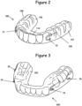
- FIG. 1 illustrates one embodiment of the present oral appliance.
- the present appliance 1 generally includes an upper tray 100, a lower tray 200, and elastic bands 300.
- the upper tray 100 has an inner surface 101, an outer surface 102, an upper surface 103, a lower surface 104, an anterior portion 105, a posterior portion 106, a right side 107, a left side 108, a buccal surface 109, and a labial surface 110.
- the lower tray 200 has an inner surface 201, an outer surface 202, an upper surface 203, a lower surface 204, an anterior portion 205, a posterior portion 206, a right side 207, a left side 208, a buccal surface 209, and a labial surface 210.
- the upper tray 100 is forming a receptacle 50 which is formed to retain the maxillary teeth of a user of the present appliance 1.
- the receptacle is formed so that the inner surface 101 matches the maxillary dentition of the user, in order to provide a comfortable and tights fit.
- the receptacle can contain, for example, one or more inner surfaces 101 corresponding to the exterior surfaces of the central incisors 330, lateral incisors 335, cuspids 340, first bicuspids 345, second bicuspids 350, and/or molars 355 of a user.
- the lower tray 200 is formed with a receptacle for retaining the mandibular teeth of the user in the same manner as the upper tray 100.
- the upper tray 100 is placed over the lower tray 200, such that the lower surface 104 contacts the upper surface 203 of the lower tray 200. In use, this will generally be done by placing the user's maxillary teeth in the upper tray 100 and placing the user's mandibular teeth in the lower tray 200 and then contacting trays.
- Elastic bands 300 are then used to connect each of the fasteners 30 on the lower tray 200 to a fastener 30 on the upper tray 100.
- the elastic bands 300 extend between fasteners 30 located on the outer, buccal surfaces of the trays.
- An upper right side fastener 32 extends buccally from the outer surface 102 of the upper tray 100 adjacent the portion of the receptacle 50 retaining the right maxillary first bicuspid 345, between the cuspids 340 and second bicuspids 350.
- the upper right side fastener 32 (and likewise the upper left side fastener 31, anterior lower right side fastener 34, and anterior lower left side fastener 33) can in some embodiments overlap the portion of a receptacle 50 that retains the cuspids 340 and/or second bicuspids 350 of a user.
- This fastener 30 is connected to a right side lower anterior fastener 34 extending buccally from the outer surface 202 of the lower tray 202 adjacent the portion of the receptacle retaining the right mandibular first bicuspid 345 and/or the right mandibular second bicuspid 350 by attaching an elastic band 300 (elastic band 301) to both the upper right side fastener 32 and the right side lower anterior fastener 34.
- the elastic bands 300 are in the form of circular bands, as are commonly used in orthodontic appliances, and elastic bands 301 is a fixed by stretching it from the upper right side fastener 32 to the right side lower anterior fastener 34.
- the upper right side fastener 32 is likewise connected to a posterior lower right side fastener 36 located on the buccal surface 209 in the posterior portion 205 of the lower tray 200, preferably adjacent the portion of the receptacle 50 of the lower tray 200 retaining one of the posterior molars 355, such as the second molar or third molar.
- the upper right side fastener 32 is connected to the posterior lower right side fastener 36 with an elastic band 302, in the same manner that the elastic band 301 connects upper right side fastener 32 to right side lower anterior fastener 34.
- separate elastic bands 300 are used to connect the upper right side fastener 32 to each of the right side lower anterior fastener 34 and the posterior lower right side fastener 36, but in some embodiments a single elastic band 300 may be used.
- the upper left side fastener 31 is connected by elastic bands 303 and 304 to a left side lower anterior fastener 33 and the posterior lower left side fastener 35 in the same manner as previously described for the right side of the present appliance 1.
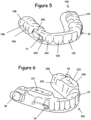
- the fasteners 30 can be any of a number of fasteners known to the art.
- hooks 40 and buttons 30 are exemplified.
- the hooks 40 comprise a proximal end 42 which is attached to the buccal surface 109, 209 of a respective tray of the present appliance 1, for example by being embedded within a polymer comprising the upper tray 100 or lower tray 200, respectively.
- the distal ends 44 of the hooks extend outwardly, and preferably extend anteriorly so as not to extend unduly toward a subject's cheek.
- Hooks 40 typically include a bend, in order to help retain the elastics 300.
- the buttons 30 used in the present appliance can include a laterally (horizontally) extending portion 52 to which an elastic band 300 can be secured.
- a circumferential "button" portion 54 extending away from the axis of the laterally extending portion 52 is preferably included at the distal end of a buccal button 30 in order to better secure an elastic band 300 on the laterally extending portion 52.
- the circumferential portions 54 are preferably ovoid or elliptically-shaped and are oriented approximately parallel to the buccal surface of the upper or lower tray.
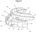
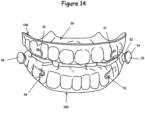
- the present appliance 1 in some embodiments includes a bite plane or surface 220 on the upper surface of the lower tray 200, on both the right side and the left side, forming a right side bite surface 221 and a left side bite surface 222.
- the bite surface 220 are horizontal and are each disposed vertically higher than other portions of the upper surface of the lower tray so that the lower surface of the upper tray contacts the bite surfaces 220 when the upper tray 100 is placed in contact with the lower tray 200.
- the flat occlusal bite plane 220 is preferably placed over the bicuspid/first molar area of the lower tray 200, opening the vertical axis of the appliance 1.
- the anterior area between the upper and lower segments is left open to allow for tongue space and unencumbered breathing.
- an anterior bite surface 225 is provided on the upper surface of the anterior portion of the lower tray 200, in order to provide a three-point fit together with the right side bite surface 221 and a left side bite surface 222.
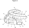
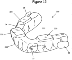
- a laterally extending band 500 can be optionally used in some embodiments of the present appliance, to restrain a user's tongue, and in these embodiments the bite surfaces 220 provide a vertical space in the posterior portion of the present appliance so that the band 500 can be attached at either end to buttons 30.
- the laterally extending band 500 can be attached to the upper tray 100 with retainers 410 in order to restrain a user's tongue.
- the retainers 410 extend rearwardly from the posterior end of the upper tray.
- a wire 412 is attached at a proximal end to the upper tray 100 (such as by being embedded in the tray material), and at the distal end a fastener 414 is provided to attach to the band 500.
- the fastener 414 comprises a button portion for insertion into a corresponding opening in the band 500.
- the lower tray 200 can be provided with tongue support pads 440 extending laterally inward from the labial surface of the lower tray 200. Such pads are likewise preferably attached to the lower tray 200 with wires or other rigid but flexible (adjustable) connectors so that their position can be adjusted. As shown in Figure 9 , the lower tray 200 can also be provided with an opening 250 in the lower anterior surface of the lower tray to guide placement of the subject's tongue.
- One of the advantages of the present appliance 1 is that standard orthodontic elastic bands, such as continuous, generally circular elastic bands 300, can be used to apply a light force to keep the upper tray 100 and lower tray 200 in the proper relative position to one another in a subject's mouth.
- Elastics connecting the upper fasteners to the lower anterior fasteners control vertical positioning of the appliance while the elastics connecting the upper fasteners to the lower posterior fasteners control anterior-posterior movement of the subject's mandible and jaw.
- the use of such lower force elastics in this manner provides greater comfort and less pressure on teeth.
- the elastic bands used in the present appliance 1 can be 3/16 inch (4.8 mm), 1 ⁇ 4 inch (6.35 mm), and/or 5/16 inch (7.87 mm) in diameter, with 3/16 inch being preferred.
- the amount of force imparted by the bands can be varied by using bands of different weights, for example bands having weights of 170 grams, 227 grams, 454 grams and/or 680 grams (6 ounces, 8 ounces, 16 ounces and/or 24 ounces).
- the weight of the bands varies with the thickness of the band material.
- the force imparted by a band can be as much as 4 or 6 Newtons, forces of between 0.9 Newton and 3 Newtons are preferred, more preferably a force of between 1.4 Newtons and 2.4 Newtons.
- the force exerted by an elastic band can be measured, for example, with a universal testing machine, such as the Emic DL 500MF testing machine (Emic Co, Sao Paulo, Brazil).
- Non-latex elastic bands are preferably used, in order to avoid an allergic reaction by a subject, and the bands preferably have a diameter of 3/16 inch (5 millimeters).
- the trays of the present oral appliance can be formed from a variety of orally compatible materials, typically polymers.
- acrylic is used to form the present appliance.
- Thermoplastic polymers are typically used in the present appliance, but thermosets, thermoplastic elastomers, and other materials can also be used.
- the thermoplastic materials that are used must be capable of retaining their shape when used by a subject, and thus must remain solid at about 37.8 degrees Celcius (100 degrees Fahrenheit) and preferably remain solid at somewhat higher temperatures, such as at 43.3 degrees Celcius (110 degrees Fahrenheit), 48.9 degrees Celcius (120 degrees Fahrenheit) or higher.
- the materials used to form the present trays also preferably become deformable at a temperature of 100 degrees Celcius (212 degrees Fahrenheit) or less, so that they can be made plastic by being placed in boiling water.
- the material is not deformable at less than 48.9 degrees Celcius (120 degrees Fahrenheit), preferably at not less than 62.8 degrees Celcius (145 degrees Fahrenheit).
- the thermoplastic materials are copolymers of ethylene and vinyl acetate.
- vinyl acetate is used in an amount of at least 25% by weight, more preferably between 25% and 35% by weight.
- Commercially available materials of this type are currently used in oral appliances known as "boil and bite" appliances.
- One such material is an ethylene vinyl acetate copolymer manufactured by the DuPont Company under the trade name ELVAX ® .
- thermoplastic materials commonly used in "boil and bite” dental appliances, allows the present appliance to be produced and fitted to a subject's mouth inexpensively and conveniently.
- the walls forming the interior passageways of the appliance are designed to allow such a relatively soft and less rigid material to be used to form the present appliance but still allow such interior passageways to be present in the appliance.
- the present appliance can be formed from more rigid materials, preferably plastic, which can be produced by a laboratory or other specialist for a subject.
- the present appliance can be formed in ways known to the art, such as by injection molding.
- the molded blank can then be imparted with a dental impression of a subject's teeth, so that the appliance can be securely retained in the mouth of the subject.
- This can be performed using known methods.
- the present appliance is a "boil and bite" type appliance
- the upper dental tray 100 and lower dental tray 200 are first evaluated for their fit with a subject's mouth. Different sizes of the present appliance can be provided for patients with differently sized mouths. After this, the trays of the appliance can be softened, preferably by placing the appliance in near boiling water for between several seconds and one minute.
- the softened appliance is then placed in the subject's mouth in alignment with the subject's upper and lower teeth, and the subject is instructed to bite into the softened material to make an impression of the teeth in the softened material.
- the tray material is then allowed to cool in the mouth for approximately one minute, after which the appliance is preferably soaked in cold water for an additional minute. Creating a customized dental impression in the trays of the present appliance in other ways and using other materials can be accomplished by one of skill in the art using known methods.
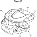
- elastic bands 300 are placed on the buccal fasteners as shown in Figure 1 .
- the lateral posterior elastic band (optional) runs across the arch from the midpoint on the posterior molars.
- the occlusal build-up on the lower segment allows for clearance of the blue cross-arch elastic.
- the slope in the buccal portion on the lower tray 200 allows for proper placement of the anterior-posterior (diagonal) elastic 320.
- This elastic runs from the anterior of the upper tray 100 to the posterior of the lower tray 200 as shown.
- the amount of desired advancement is controlled by selection of elastic size and strength.
- the elastic that is placed vertically from the buttons in the first bicuspid region on both trays allows for a "closed-mouth" posture during sleep.
Landscapes
- Health & Medical Sciences (AREA)
- Otolaryngology (AREA)
- Pulmonology (AREA)
- Nursing (AREA)
- Orthopedic Medicine & Surgery (AREA)
- Engineering & Computer Science (AREA)
- Biomedical Technology (AREA)
- Heart & Thoracic Surgery (AREA)
- Vascular Medicine (AREA)
- Life Sciences & Earth Sciences (AREA)
- Animal Behavior & Ethology (AREA)
- General Health & Medical Sciences (AREA)
- Public Health (AREA)
- Veterinary Medicine (AREA)
- Orthopedics, Nursing, And Contraception (AREA)
Claims (9)
- Appareil buccal pour apnée du sommeil, comprenant :(a) un plateau supérieur (100) possédant une surface supérieure (103), une surface inférieure (104), une partie antérieure (105), une partie
postérieure (106), un côté droit (107), un côté gauche (108), une surface buccale (109), une surface labiale (110) et une surface externe, le plateau supérieur (100) comprenant :un réceptacle de plateau supérieur (50) formé dans la surface supérieure (103), le réceptacle de plateau supérieur possédant une surface interne (101) formée de manière à retenir les dents maxillaires d'un sujet ;un élément de fixation de plateau supérieur côté droit (32) s'étendant buccalement depuis la surface externe du plateau supérieur (100) adjacente à la partie du réceptacle de plateau supérieur retenant la première prémolaire maxillaire droite et/ou la seconde prémolaire maxillaire droite ; etun élément de fixation de plateau supérieur côté gauche (31) s'étendant buccalement depuis la surface externe du plateau supérieur (100) adjacente à la partie du réceptacle de plateau supérieur retenant la première prémolaire maxillaire gauche et/ou la seconde prémolaire maxillaire gauche ;(b) un plateau inférieur (200) possédant une surface supérieure (203), une surface inférieure (204), une partie antérieure (205), une partie
postérieure (206), un côté droit (207), un côté gauche (208), une surface buccale (209), une surface labiale (210) et une surface externe, le plateau inférieur (200) comprenant :un réceptacle de plateau inférieur (50) formé dans la surface inférieure (204), le réceptacle de plateau inférieur (50) possédant une surface interne (201) formée de manière à retenir les dents mandibulaires du sujet ;un élément de fixation antérieur côté droit (34) s'étendant buccalement depuis la surface externe du plateau inférieur (200) adjacente à la partie du réceptacle de plateau inférieur (50) retenant la première prémolaire mandibulaire droite et/ou la seconde prémolaire mandibulaire droite ;un élément de fixation antérieur côté gauche (33) s'étendant buccalement depuis la surface externe du plateau inférieur (200) adjacente à la partie du réceptacle de plateau inférieur (50) retenant la première prémolaire mandibulaire gauche et/ou la seconde prémolaire mandibulaire gauche ;un élément de fixation postérieur côté droit (36) s'étendant buccalement depuis la surface externe du plateau inférieur (200) adjacente à la partie du réceptacle de plateau inférieur (50) retenant une molaire mandibulaire droite ; etun élément de fixation postérieur côté gauche (35) s'étendant buccalement depuis la surface externe du plateau inférieur (200) adjacente à la partie du réceptacle de plateau inférieur (50) retenant une molaire mandibulaire gauche ; et(c) une pluralité de bandes élastiques orthodontiques (300) incluant :une première bande élastique orthodontique (301) reliant l'élément de fixation de plateau supérieur côté gauche (31) du plateau supérieur (100) à l'élément de fixation antérieur côté gauche (33),une deuxième bande élastique orthodontique (302) reliant l'élément de fixation de plateau supérieur côté gauche (31) du plateau supérieur (100) à l'élément de fixation postérieur côté gauche (35) du plateau inférieur (200),une troisième bande élastique orthodontique (303) reliant l'élément de fixation de plateau supérieur côté droit (32) du plateau supérieur (100) à l'élément de fixation antérieur côté droit (34) du plateau inférieur (200), etune quatrième bande élastique orthodontique (304) reliant l'élément de fixation de plateau supérieur côté droit (32) du plateau supérieur (100) à l'élément de fixation postérieur côté droit (36) du plateau inférieur (200),dans lequel les bandes élastiques orthodontiques exercent une force comprise entre 0,9 Newton et 3 Newtons sous tension, etdans lequel la mâchoire inférieure est libre de se déplacer vers l'avant lors de l'utilisation. - Appareil selon la revendication 1, dans lequel les bandes élastiques orthodontiques (300) exercent une force comprise entre 1,4 Newton et 2,4 Newtons lorsqu'elles sont mises sous tension.
- Appareil selon la revendication 1 ou 2, dans lequel la largeur des bandes élastiques orthodontiques (300) est comprise entre 4,8 mm et 7,9 mm.
- Appareil selon la revendication 1, dans lequel l'élément de fixation antérieur côté gauche (33) du plateau supérieur (100) est positionné latéralement par rapport à la partie du réceptacle de plateau supérieur retenant la première prémolaire maxillaire gauche et l'élément de fixation antérieur côté droit (34) du plateau supérieur (100) est positionné latéralement par rapport à la partie du réceptacle de plateau supérieur retenant la première prémolaire maxillaire droite.
- Appareil selon la revendication 1, dans lequel l'élément de fixation antérieur côté gauche (33) du plateau inférieur (200) est positionné latéralement par rapport à la partie du réceptacle de plateau inférieur (50) retenant la première prémolaire maxillaire gauche et l'élément de fixation antérieur côté droit (34) du plateau inférieur (200) est positionné latéralement par rapport à la partie du réceptacle de plateau inférieur (50) retenant la première prémolaire maxillaire droite.
- Appareil selon l'une quelconque des revendications 1 à 5, dans lequel un ou plusieurs des éléments de fixation (30) sont des boutons comprenant une partie tige et une partie circonférentielle, dans lequel la partie tige est fixée au niveau d'une extrémité proximale à la surface externe du plateau supérieur (100) ou du plateau inférieur (200), la tige étant fixée au niveau d'une extrémité distale à la partie circonférentielle.
- Appareil selon l'une quelconque des revendications 1 à 6, dans lequel un ou plusieurs des éléments de fixation (30) sont des crochets (40).
- Appareil selon l'une quelconque des revendications 1 à 7, dans lequel la surface supérieure (203) du côté droit (207) du plateau inférieur (200) comprend une surface de morsure côté droit (221) et la surface supérieure (203) du côté gauche (208) du plateau inférieur (200) comprend une surface de morsure côté gauche (222), dans lequel les surfaces de morsure sont horizontales et sont chacune disposées verticalement plus haut que les autres parties de la surface supérieure du plateau inférieur (200), de sorte que la surface inférieure (104) du plateau supérieur (100) entre en contact avec les surfaces de morsure lorsque le plateau supérieur (100) est mis en contact avec le plateau inférieur (200).
- Appareil selon la revendication 8, dans lequel le plateau inférieur (200) comprend en outre une surface de morsure antérieure (225), dans lequel la surface de morsure antérieure est horizontale et est disposée verticalement plus haut que les autres parties de la surface supérieure (203) du plateau inférieur (200) de sorte que la surface inférieure (104) du plateau supérieur (100) entre en contact avec la surface de morsure antérieure lorsque le plateau supérieur (100) est mis en contact avec le plateau inférieur (200).
Applications Claiming Priority (2)
| Application Number | Priority Date | Filing Date | Title |
|---|---|---|---|
| US201462004867P | 2014-05-29 | 2014-05-29 | |
| PCT/US2015/033423 WO2015184419A1 (fr) | 2014-05-29 | 2015-05-29 | Appareil buccal pour le traitement de l'apnée du sommeil |
Publications (4)
| Publication Number | Publication Date |
|---|---|
| EP3148488A1 EP3148488A1 (fr) | 2017-04-05 |
| EP3148488A4 EP3148488A4 (fr) | 2018-01-31 |
| EP3148488B1 true EP3148488B1 (fr) | 2025-02-26 |
| EP3148488C0 EP3148488C0 (fr) | 2025-02-26 |
Family
ID=54699949
Family Applications (1)
| Application Number | Title | Priority Date | Filing Date |
|---|---|---|---|
| EP15798691.0A Active EP3148488B1 (fr) | 2014-05-29 | 2015-05-29 | Appareil buccal pour le traitement de l'apnée du sommeil |
Country Status (5)
| Country | Link |
|---|---|
| US (1) | US20170216084A1 (fr) |
| EP (1) | EP3148488B1 (fr) |
| CN (1) | CN106456354B (fr) |
| AU (1) | AU2015266592B2 (fr) |
| WO (1) | WO2015184419A1 (fr) |
Families Citing this family (8)
| Publication number | Priority date | Publication date | Assignee | Title |
|---|---|---|---|---|
| US20180071134A1 (en) * | 2016-09-14 | 2018-03-15 | Gordon Honig | Device for treatment of sleep related disorders, a process to make the device and a process to use the device |
| KR101959537B1 (ko) * | 2017-04-21 | 2019-03-18 | 남관우 | 코골이 방지용 하악골 전방 견인 장치 |
| US12138198B2 (en) | 2017-05-26 | 2024-11-12 | Diamond Orthotic Laboratory, Llc | Oral appliance device |
| CN111954507B (zh) * | 2018-01-31 | 2023-03-24 | 奥丁睡眠有限责任公司 | 具有连接器的睡眠呼吸暂停口腔器具 |
| US11259955B2 (en) | 2019-05-29 | 2022-03-01 | Pankaj Pal Singh | Apparatus and methods to convert dental, oral, orthodontic appliances, retainers, and dentures into a multifunctional oral appliance |
| CN110251248B (zh) * | 2019-05-31 | 2024-12-27 | 深圳牙领科技有限公司 | 一种具有咬合导向的牙齿矫治器 |
| WO2021178972A1 (fr) * | 2020-03-06 | 2021-09-10 | R.I.P. Llc | Appareil buccal destiné à être utilisé avec un casque cpap |
| US20240299207A1 (en) * | 2023-03-08 | 2024-09-12 | G-Force, Inc | Digitally printed arches with elastic advancements for anti-snoring |
Family Cites Families (17)
| Publication number | Priority date | Publication date | Assignee | Title |
|---|---|---|---|---|
| US4505672A (en) * | 1983-11-14 | 1985-03-19 | Kurz Craven H | Two-piece gnathologic orthodontic positioner |
| US5868138A (en) * | 1993-04-13 | 1999-02-09 | Silent Knight Ventures, Inc. | Dental appliance for treatment of snoring and obstructive sleep apnea |
| AUPR371401A0 (en) * | 2001-03-14 | 2001-04-12 | Murray, Andrew Fraser Hamish | Appliances for treating sleep apnoea |
| US6827574B2 (en) * | 2001-04-12 | 2004-12-07 | Kevin L. Payton | Skeletal transmucosal orthodontic plate and method |
| CN2619601Y (zh) * | 2003-04-27 | 2004-06-09 | 吴占敖 | 阻塞型睡眠呼吸暂停综合症的防治装置 |
| US6983752B2 (en) | 2004-03-11 | 2006-01-10 | Sleep Sound Services Zzz | Dental appliance for the treatment of sleep disorders |
| US7451767B2 (en) * | 2005-06-23 | 2008-11-18 | Bryan Keropian | Sleep appliance |
| US7637262B2 (en) * | 2006-06-12 | 2009-12-29 | Bailey Dennis R | Anti-retrusion oral appliance |
| JP4998958B2 (ja) * | 2006-08-25 | 2012-08-15 | 国立大学法人 長崎大学 | 睡眠時無呼吸症候群又はいびき症改善下顎前方位型口腔内装置用コネクター |
| KR100856672B1 (ko) * | 2007-03-16 | 2008-09-04 | 홍이표 | 코골이 및 수면무호흡증의 교정구 |
| JP4936061B2 (ja) * | 2007-07-24 | 2012-05-23 | 晃 北村 | 口腔内装置及びその製造方法 |
| US20090036889A1 (en) | 2007-07-30 | 2009-02-05 | Callender R Sam | Method and apparatus for treatment of sleep apnea |
| US8127769B2 (en) * | 2007-11-18 | 2012-03-06 | Dreamscape Medical Llc | Integrated oral appliance for sleep-disordered breathing |
| DE202008011841U1 (de) * | 2008-09-06 | 2008-11-13 | Toussaint, Winfried, Dr. | Verstellbare Unterkieferprotrusionsschiene zur Behandlung von Schnarchen und obstruktiver Schlafapnoe |
| CN201422945Y (zh) * | 2009-05-27 | 2010-03-17 | 山东大学 | 一种可调型下颌前置式osahs治疗器 |
| CN202908863U (zh) * | 2012-10-30 | 2013-05-01 | 朱房勇 | 一种热压膜成型的磁力矫治器 |
| CN203370010U (zh) * | 2013-02-04 | 2014-01-01 | 张湘民 | 舌背弹性牵引装置 |
-
2015
- 2015-05-29 EP EP15798691.0A patent/EP3148488B1/fr active Active
- 2015-05-29 US US15/327,963 patent/US20170216084A1/en not_active Abandoned
- 2015-05-29 AU AU2015266592A patent/AU2015266592B2/en active Active
- 2015-05-29 CN CN201580031937.8A patent/CN106456354B/zh active Active
- 2015-05-29 WO PCT/US2015/033423 patent/WO2015184419A1/fr not_active Ceased
Also Published As
| Publication number | Publication date |
|---|---|
| AU2015266592B2 (en) | 2020-01-23 |
| CN106456354B (zh) | 2020-04-10 |
| EP3148488C0 (fr) | 2025-02-26 |
| EP3148488A4 (fr) | 2018-01-31 |
| EP3148488A1 (fr) | 2017-04-05 |
| US20170216084A1 (en) | 2017-08-03 |
| CN106456354A (zh) | 2017-02-22 |
| WO2015184419A1 (fr) | 2015-12-03 |
| AU2015266592A1 (en) | 2017-01-12 |
Similar Documents
| Publication | Publication Date | Title |
|---|---|---|
| EP3148488B1 (fr) | Appareil buccal pour le traitement de l'apnée du sommeil | |
| US11517403B2 (en) | Adjustable sleep apnea oral appliance | |
| US10363161B2 (en) | Sleep apnea oral appliance for use during orthodontic treatment | |
| US11672690B2 (en) | Sleep apnea oral appliance with connectors | |
| EP2032067A2 (fr) | Appareil buccal pour le traitement des ronflements et de l'apnée du sommeil | |
| JP7182792B2 (ja) | 睡眠時無呼吸、いびき、ならびに舌および口腔の再構築のための歯科用器具 | |
| US20190000662A1 (en) | Adjustable sleep apnea oral appliance | |
| US12303424B2 (en) | Adjustable sleep apnea oral appliance for use with orthodontic braces | |
| US20240423829A1 (en) | Oral appliance for treating sleep apnea | |
| IT201800002713A1 (it) | Processo di fabbricazione di maschere facciali personalizzate per il trattamento della malocclusione |
Legal Events
| Date | Code | Title | Description |
|---|---|---|---|
| STAA | Information on the status of an ep patent application or granted ep patent |
Free format text: STATUS: THE INTERNATIONAL PUBLICATION HAS BEEN MADE |
|
| PUAI | Public reference made under article 153(3) epc to a published international application that has entered the european phase |
Free format text: ORIGINAL CODE: 0009012 |
|
| STAA | Information on the status of an ep patent application or granted ep patent |
Free format text: STATUS: REQUEST FOR EXAMINATION WAS MADE |
|
| 17P | Request for examination filed |
Effective date: 20161221 |
|
| AK | Designated contracting states |
Kind code of ref document: A1 Designated state(s): AL AT BE BG CH CY CZ DE DK EE ES FI FR GB GR HR HU IE IS IT LI LT LU LV MC MK MT NL NO PL PT RO RS SE SI SK SM TR |
|
| AX | Request for extension of the european patent |
Extension state: BA ME |
|
| DAV | Request for validation of the european patent (deleted) | ||
| DAX | Request for extension of the european patent (deleted) | ||
| A4 | Supplementary search report drawn up and despatched |
Effective date: 20180105 |
|
| RIC1 | Information provided on ipc code assigned before grant |
Ipc: A61F 5/56 20060101AFI20171222BHEP |
|
| STAA | Information on the status of an ep patent application or granted ep patent |
Free format text: STATUS: EXAMINATION IS IN PROGRESS |
|
| 17Q | First examination report despatched |
Effective date: 20200302 |
|
| RAP1 | Party data changed (applicant data changed or rights of an application transferred) |
Owner name: R.I.P., LLC |
|
| GRAP | Despatch of communication of intention to grant a patent |
Free format text: ORIGINAL CODE: EPIDOSNIGR1 |
|
| STAA | Information on the status of an ep patent application or granted ep patent |
Free format text: STATUS: GRANT OF PATENT IS INTENDED |
|
| INTG | Intention to grant announced |
Effective date: 20241128 |
|
| GRAS | Grant fee paid |
Free format text: ORIGINAL CODE: EPIDOSNIGR3 |
|
| GRAA | (expected) grant |
Free format text: ORIGINAL CODE: 0009210 |
|
| STAA | Information on the status of an ep patent application or granted ep patent |
Free format text: STATUS: THE PATENT HAS BEEN GRANTED |
|
| AK | Designated contracting states |
Kind code of ref document: B1 Designated state(s): AL AT BE BG CH CY CZ DE DK EE ES FI FR GB GR HR HU IE IS IT LI LT LU LV MC MK MT NL NO PL PT RO RS SE SI SK SM TR |
|
| REG | Reference to a national code |
Ref country code: GB Ref legal event code: FG4D |
|
| REG | Reference to a national code |
Ref country code: CH Ref legal event code: EP |
|
| REG | Reference to a national code |
Ref country code: DE Ref legal event code: R096 Ref document number: 602015091101 Country of ref document: DE |
|
| REG | Reference to a national code |
Ref country code: IE Ref legal event code: FG4D |
|
| U01 | Request for unitary effect filed |
Effective date: 20250321 |
|
| U07 | Unitary effect registered |
Designated state(s): AT BE BG DE DK EE FI FR IT LT LU LV MT NL PT RO SE SI Effective date: 20250327 |
|
| U20 | Renewal fee for the european patent with unitary effect paid |
Year of fee payment: 11 Effective date: 20250528 |
|
| PG25 | Lapsed in a contracting state [announced via postgrant information from national office to epo] |
Ref country code: RS Free format text: LAPSE BECAUSE OF FAILURE TO SUBMIT A TRANSLATION OF THE DESCRIPTION OR TO PAY THE FEE WITHIN THE PRESCRIBED TIME-LIMIT Effective date: 20250526 |
|
| PG25 | Lapsed in a contracting state [announced via postgrant information from national office to epo] |
Ref country code: PL Free format text: LAPSE BECAUSE OF FAILURE TO SUBMIT A TRANSLATION OF THE DESCRIPTION OR TO PAY THE FEE WITHIN THE PRESCRIBED TIME-LIMIT Effective date: 20250226 |
|
| PG25 | Lapsed in a contracting state [announced via postgrant information from national office to epo] |
Ref country code: ES Free format text: LAPSE BECAUSE OF FAILURE TO SUBMIT A TRANSLATION OF THE DESCRIPTION OR TO PAY THE FEE WITHIN THE PRESCRIBED TIME-LIMIT Effective date: 20250226 |
|
| PGFP | Annual fee paid to national office [announced via postgrant information from national office to epo] |
Ref country code: GB Payment date: 20250521 Year of fee payment: 11 |
|
| PG25 | Lapsed in a contracting state [announced via postgrant information from national office to epo] |
Ref country code: IS Free format text: LAPSE BECAUSE OF FAILURE TO SUBMIT A TRANSLATION OF THE DESCRIPTION OR TO PAY THE FEE WITHIN THE PRESCRIBED TIME-LIMIT Effective date: 20250626 Ref country code: NO Free format text: LAPSE BECAUSE OF FAILURE TO SUBMIT A TRANSLATION OF THE DESCRIPTION OR TO PAY THE FEE WITHIN THE PRESCRIBED TIME-LIMIT Effective date: 20250526 |
|
| PG25 | Lapsed in a contracting state [announced via postgrant information from national office to epo] |
Ref country code: HR Free format text: LAPSE BECAUSE OF FAILURE TO SUBMIT A TRANSLATION OF THE DESCRIPTION OR TO PAY THE FEE WITHIN THE PRESCRIBED TIME-LIMIT Effective date: 20250226 |
|
| PG25 | Lapsed in a contracting state [announced via postgrant information from national office to epo] |
Ref country code: GR Free format text: LAPSE BECAUSE OF FAILURE TO SUBMIT A TRANSLATION OF THE DESCRIPTION OR TO PAY THE FEE WITHIN THE PRESCRIBED TIME-LIMIT Effective date: 20250527 |
|
| PG25 | Lapsed in a contracting state [announced via postgrant information from national office to epo] |
Ref country code: SM Free format text: LAPSE BECAUSE OF FAILURE TO SUBMIT A TRANSLATION OF THE DESCRIPTION OR TO PAY THE FEE WITHIN THE PRESCRIBED TIME-LIMIT Effective date: 20250226 |
|
| PG25 | Lapsed in a contracting state [announced via postgrant information from national office to epo] |
Ref country code: CZ Free format text: LAPSE BECAUSE OF FAILURE TO SUBMIT A TRANSLATION OF THE DESCRIPTION OR TO PAY THE FEE WITHIN THE PRESCRIBED TIME-LIMIT Effective date: 20250226 |
|
| PG25 | Lapsed in a contracting state [announced via postgrant information from national office to epo] |
Ref country code: SK Free format text: LAPSE BECAUSE OF FAILURE TO SUBMIT A TRANSLATION OF THE DESCRIPTION OR TO PAY THE FEE WITHIN THE PRESCRIBED TIME-LIMIT Effective date: 20250226 |
|
| REG | Reference to a national code |
Ref country code: CH Ref legal event code: H13 Free format text: ST27 STATUS EVENT CODE: U-0-0-H10-H13 (AS PROVIDED BY THE NATIONAL OFFICE) Effective date: 20251223 |
|
| PLBE | No opposition filed within time limit |
Free format text: ORIGINAL CODE: 0009261 |
|
| STAA | Information on the status of an ep patent application or granted ep patent |
Free format text: STATUS: NO OPPOSITION FILED WITHIN TIME LIMIT |
|
| PG25 | Lapsed in a contracting state [announced via postgrant information from national office to epo] |
Ref country code: CH Free format text: LAPSE BECAUSE OF NON-PAYMENT OF DUE FEES Effective date: 20250531 |
|
| PG25 | Lapsed in a contracting state [announced via postgrant information from national office to epo] |
Ref country code: MC Free format text: LAPSE BECAUSE OF FAILURE TO SUBMIT A TRANSLATION OF THE DESCRIPTION OR TO PAY THE FEE WITHIN THE PRESCRIBED TIME-LIMIT Effective date: 20250226 |
|
| 26N | No opposition filed |
Effective date: 20251127 |
|
| PG25 | Lapsed in a contracting state [announced via postgrant information from national office to epo] |
Ref country code: IE Free format text: LAPSE BECAUSE OF NON-PAYMENT OF DUE FEES Effective date: 20250529 |