EP3148604B1 - Méthode et appareil de dispositif d'assistance ventriculaire - Google Patents
Méthode et appareil de dispositif d'assistance ventriculaire Download PDFInfo
- Publication number
- EP3148604B1 EP3148604B1 EP15799117.5A EP15799117A EP3148604B1 EP 3148604 B1 EP3148604 B1 EP 3148604B1 EP 15799117 A EP15799117 A EP 15799117A EP 3148604 B1 EP3148604 B1 EP 3148604B1
- Authority
- EP
- European Patent Office
- Prior art keywords
- flow rate
- flow
- parameter value
- pressure
- assist device
- Prior art date
- Legal status (The legal status is an assumption and is not a legal conclusion. Google has not performed a legal analysis and makes no representation as to the accuracy of the status listed.)
- Active
Links
Images






Classifications
-
- A—HUMAN NECESSITIES
- A61—MEDICAL OR VETERINARY SCIENCE; HYGIENE
- A61M—DEVICES FOR INTRODUCING MEDIA INTO, OR ONTO, THE BODY; DEVICES FOR TRANSDUCING BODY MEDIA OR FOR TAKING MEDIA FROM THE BODY; DEVICES FOR PRODUCING OR ENDING SLEEP OR STUPOR
- A61M60/00—Blood pumps; Devices for mechanical circulatory actuation; Balloon pumps for circulatory assistance
- A61M60/10—Location thereof with respect to the patient's body
- A61M60/122—Implantable pumps or pumping devices, i.e. the blood being pumped inside the patient's body
- A61M60/126—Implantable pumps or pumping devices, i.e. the blood being pumped inside the patient's body implantable via, into, inside, in line, branching on, or around a blood vessel
- A61M60/148—Implantable pumps or pumping devices, i.e. the blood being pumped inside the patient's body implantable via, into, inside, in line, branching on, or around a blood vessel in line with a blood vessel using resection or like techniques, e.g. permanent endovascular heart assist devices
-
- A—HUMAN NECESSITIES
- A61—MEDICAL OR VETERINARY SCIENCE; HYGIENE
- A61M—DEVICES FOR INTRODUCING MEDIA INTO, OR ONTO, THE BODY; DEVICES FOR TRANSDUCING BODY MEDIA OR FOR TAKING MEDIA FROM THE BODY; DEVICES FOR PRODUCING OR ENDING SLEEP OR STUPOR
- A61M60/00—Blood pumps; Devices for mechanical circulatory actuation; Balloon pumps for circulatory assistance
- A61M60/10—Location thereof with respect to the patient's body
- A61M60/122—Implantable pumps or pumping devices, i.e. the blood being pumped inside the patient's body
- A61M60/165—Implantable pumps or pumping devices, i.e. the blood being pumped inside the patient's body implantable in, on, or around the heart
- A61M60/178—Implantable pumps or pumping devices, i.e. the blood being pumped inside the patient's body implantable in, on, or around the heart drawing blood from a ventricle and returning the blood to the arterial system via a cannula external to the ventricle, e.g. left or right ventricular assist devices
-
- A—HUMAN NECESSITIES
- A61—MEDICAL OR VETERINARY SCIENCE; HYGIENE
- A61M—DEVICES FOR INTRODUCING MEDIA INTO, OR ONTO, THE BODY; DEVICES FOR TRANSDUCING BODY MEDIA OR FOR TAKING MEDIA FROM THE BODY; DEVICES FOR PRODUCING OR ENDING SLEEP OR STUPOR
- A61M60/00—Blood pumps; Devices for mechanical circulatory actuation; Balloon pumps for circulatory assistance
- A61M60/20—Type thereof
- A61M60/205—Non-positive displacement blood pumps
- A61M60/216—Non-positive displacement blood pumps including a rotating member acting on the blood, e.g. impeller
-
- A—HUMAN NECESSITIES
- A61—MEDICAL OR VETERINARY SCIENCE; HYGIENE
- A61M—DEVICES FOR INTRODUCING MEDIA INTO, OR ONTO, THE BODY; DEVICES FOR TRANSDUCING BODY MEDIA OR FOR TAKING MEDIA FROM THE BODY; DEVICES FOR PRODUCING OR ENDING SLEEP OR STUPOR
- A61M60/00—Blood pumps; Devices for mechanical circulatory actuation; Balloon pumps for circulatory assistance
- A61M60/20—Type thereof
- A61M60/205—Non-positive displacement blood pumps
- A61M60/216—Non-positive displacement blood pumps including a rotating member acting on the blood, e.g. impeller
- A61M60/226—Non-positive displacement blood pumps including a rotating member acting on the blood, e.g. impeller the blood flow through the rotating member having mainly radial components
- A61M60/232—Centrifugal pumps
-
- A—HUMAN NECESSITIES
- A61—MEDICAL OR VETERINARY SCIENCE; HYGIENE
- A61M—DEVICES FOR INTRODUCING MEDIA INTO, OR ONTO, THE BODY; DEVICES FOR TRANSDUCING BODY MEDIA OR FOR TAKING MEDIA FROM THE BODY; DEVICES FOR PRODUCING OR ENDING SLEEP OR STUPOR
- A61M60/00—Blood pumps; Devices for mechanical circulatory actuation; Balloon pumps for circulatory assistance
- A61M60/50—Details relating to control
- A61M60/508—Electronic control means, e.g. for feedback regulation
- A61M60/515—Regulation using real-time patient data
- A61M60/523—Regulation using real-time patient data using blood flow data, e.g. from blood flow transducers
-
- A—HUMAN NECESSITIES
- A61—MEDICAL OR VETERINARY SCIENCE; HYGIENE
- A61M—DEVICES FOR INTRODUCING MEDIA INTO, OR ONTO, THE BODY; DEVICES FOR TRANSDUCING BODY MEDIA OR FOR TAKING MEDIA FROM THE BODY; DEVICES FOR PRODUCING OR ENDING SLEEP OR STUPOR
- A61M60/00—Blood pumps; Devices for mechanical circulatory actuation; Balloon pumps for circulatory assistance
- A61M60/50—Details relating to control
- A61M60/508—Electronic control means, e.g. for feedback regulation
- A61M60/515—Regulation using real-time patient data
- A61M60/531—Regulation using real-time patient data using blood pressure data, e.g. from blood pressure sensors
-
- A—HUMAN NECESSITIES
- A61—MEDICAL OR VETERINARY SCIENCE; HYGIENE
- A61M—DEVICES FOR INTRODUCING MEDIA INTO, OR ONTO, THE BODY; DEVICES FOR TRANSDUCING BODY MEDIA OR FOR TAKING MEDIA FROM THE BODY; DEVICES FOR PRODUCING OR ENDING SLEEP OR STUPOR
- A61M2205/00—General characteristics of the apparatus
- A61M2205/33—Controlling, regulating or measuring
- A61M2205/3331—Pressure; Flow
- A61M2205/3334—Measuring or controlling the flow rate
-
- A—HUMAN NECESSITIES
- A61—MEDICAL OR VETERINARY SCIENCE; HYGIENE
- A61M—DEVICES FOR INTRODUCING MEDIA INTO, OR ONTO, THE BODY; DEVICES FOR TRANSDUCING BODY MEDIA OR FOR TAKING MEDIA FROM THE BODY; DEVICES FOR PRODUCING OR ENDING SLEEP OR STUPOR
- A61M2205/00—General characteristics of the apparatus
- A61M2205/50—General characteristics of the apparatus with microprocessors or computers
-
- A—HUMAN NECESSITIES
- A61—MEDICAL OR VETERINARY SCIENCE; HYGIENE
- A61M—DEVICES FOR INTRODUCING MEDIA INTO, OR ONTO, THE BODY; DEVICES FOR TRANSDUCING BODY MEDIA OR FOR TAKING MEDIA FROM THE BODY; DEVICES FOR PRODUCING OR ENDING SLEEP OR STUPOR
- A61M2230/00—Measuring parameters of the user
- A61M2230/30—Blood pressure
-
- A—HUMAN NECESSITIES
- A61—MEDICAL OR VETERINARY SCIENCE; HYGIENE
- A61M—DEVICES FOR INTRODUCING MEDIA INTO, OR ONTO, THE BODY; DEVICES FOR TRANSDUCING BODY MEDIA OR FOR TAKING MEDIA FROM THE BODY; DEVICES FOR PRODUCING OR ENDING SLEEP OR STUPOR
- A61M60/00—Blood pumps; Devices for mechanical circulatory actuation; Balloon pumps for circulatory assistance
- A61M60/50—Details relating to control
- A61M60/508—Electronic control means, e.g. for feedback regulation
- A61M60/562—Electronic control means, e.g. for feedback regulation for making blood flow pulsatile in blood pumps that do not intrinsically create pulsatile flow
Definitions
- the present invention relates to a method and apparatus for use with a ventricular assist device that is assisting cardiac function of a biological subject, and to a method and apparatus for determining a blood pressure parameter value and/or controlling operation of the ventricular assist device.
- Example third generation pumps from Ventrassist and HeartWare use an impeller rotating at a fixed speed (approximately 2000 rpm and 2700 rpm respectively) and rely on variations in preload and afterload to control pump output.
- Flow is related to head pressure, which equates to the difference between aortic and left ventricular pressure, with an increase in preload or decrease in afterload leading to an increase in output. Consequently, even at constant speed, flow through a cfLVAD increases with activity, mainly as a result of increased preload. However, this increase is modest in comparison to the physiological response to exercise.
- the weak preload and strong afterload sensitivities in cfLVADs relative to normal hearts mean that patients implanted with these devices are restricted in their ability to increase cardiac output with exercise when compared to normal subjects.
- US2004/0152944 describes a left ventricular assist device (LVAD) in which a rotodynamic blood pump is powered by a brushless DC motor.
- a power supply supplies power to the motor.
- Three feedback channels, one for each of voltage, current, and motor speed lead to a microcontroller or microprocessor.
- the three feedback waveforms are analyzed, and from these waveforms, motor input power, patient heart rate, current pump flow rate, and systemic pressure are determined.
- the microprocessor then calculates a desired flow rate proportional to the patient heart rate.
- the microprocessor communicates a new power output to a commutation circuit, which regulates power to the motor.
- the pump also includes safety checks that are prioritized over desired pump flow. These include prevention of ventricular suction, low pulsatility, minimum and maximum pump speed, minimum peed-relative pump flow, minimum absolute pump flow, minimum and maximum motor input power.
- WO2003/057280 describes a physiologic control method and system for an implantable blood pump includes operating the pump at a predetermined speed and monitoring the patient's diastolic pump flow rate.
- the invention seeks to provide apparatus for use with a ventricular assist device that is assisting cardiac function of a biological subject, the apparatus including an electronic processing device that:
- the ventricular assist device includes a rotating impeller, and wherein the electronic processing device controls blood flow through the ventricular assist device by causing a rate of rotation of the impeller to be adjusted.
- the electronic processing device determines diastole as a period of the cardiac cycle from the flow rate minima to a proportion of the flow rate maxima and wherein the proportion of the flow rate maxima is at least one of:
- the electronic processing device at least one of:
- the at least one blood pressure parameter value is at least partially indicative of at least one of:
- the electronic processing device is at least one of:
- the electronic processing device determines the blood flow rate at least one of:
- the invention seeks to provide a method for use with a ventricular assist device that is assisting cardiac function of a biological subject, the method including:
- the apparatus includes a processing system 100 that is coupled to a VAD 120, which is in turn connected to the heart 130 of a subject.
- the VAD is coupled via respective inlet and outlet cannulas 121, 122 to the left ventricle 131 and aorta 132, and is therefore functioning as a left ventricular assist device (LVAD), although this is not essential and similar techniques to those described can also be applied to right ventricular assist devices (RVADs) coupled to the right ventricle and pulmonary artery.
- the VAD is a continuous flow VAD (cfVAD) in which an impeller is continuously rotated within a cavity, to thereby pump blood from the ventricle into the aorta.
- the VAD 120 can be a standard VAD known in the art, such as a Heartware HVAD, Ventracor Ventrassist, or the like, and this will not therefore be described in further detail.
- the processing system 100 is coupled to the VAD 120 via a controller 110, via a wired or wireless connection.
- the controller 110 operates to control the VAD and in particular control rotation of the impeller and optionally monitor operating characteristics of the VAD.
- This arrangement is not essential and alternatively the processing system 100 and controller 110 can be implemented as a single piece of hardware, although it will be appreciated that use of a separate processing system that interfaces with an existing controller can reduce regulatory requirements needed for implementation.
- the processing system 100 includes an electronic processing device, such as a microprocessor, that is adapted to determine information regarding the flow rate of blood through the VAD 120 and then use this to either control operation of the VAD, or determine blood pressure parameter values, as will now be described with reference to Figure 2 .
- an electronic processing device such as a microprocessor
- the electronic processing device determines a flow rate of blood through the VAD 120.
- the flow rate can be determined in any suitable manner and can be obtained from sensors incorporated within the VAD 120, or alternatively could be derived from operating characteristics of the VAD 120, for example by monitoring rotation of the impeller as described for example in US-8,506,470 .
- the flow rate could be calculated by the electronic processing device or alternatively could be received as flow rate data from the controller 110, depending on the preferred implementation.
- the electronic processing device analyses the flow rate to determine a flow parameter value at least partially indicative of a change in flow rate during diastole. This can be achieved in any suitable manner, but typically involves identifying individual heart beats, analysing these to determine a portion of the heart beat corresponding to diastolic flow, and then calculating the flow parameter value.
- the flow parameter value can be of any appropriate form, but is typically the flow rate gradient corresponding to a rate of change of flow rate of blood through the VAD, as will be described in more detail below.
- the electronic processing device can use the flow parameter value to derive at least one blood pressure parameter value at least partially indicative of a blood pressure in the biological subject.
- the rate of change in blood flow rate through the VAD during diastole is related to the blood pressure within the ventricle, and in particular, a ventricular filling pressure, such as the ventricular EDP (End Diastole Pressure). Accordingly, this allows the electronic processing device to derive information regarding blood pressure within the heart solely from information regarding the flow rate of blood through the VAD.
- determination of the flow parameter value allows important physiological information to be derived without requiring the need for a sensor to be implanted within the patient.
- MAP mean arterial pressure
- the parameter value can be used to control operation of the VAD.
- this can be used to adjust the pumping capacity of the VAD to accommodate changes in physiological status, for example to avoid suck-down events, provide additional pumping during exercise, or the like.
- the above described method can be used to determine blood pressure parameter values that cannot otherwise be derived without the need to implant sensors within the heart, which is extremely undesirable, as well as allowing the operation of the VAD to be controlled to thereby optimize the assistance provided to the heart.
- the processing system 100 includes at least one microprocessor 101, a memory 102, an optional input/output device 103, such as a keyboard and/or display, and an external interface 104, interconnected via a bus 105 as shown.
- the external interface 104 can be utilised for connecting the processing system 100 to the controller 110 and optionally to peripheral devices, such as the communications networks, databases, or the like.
- peripheral devices such as the communications networks, databases, or the like.
- a single external interface 104 is shown, this is for the purpose of example only and in practice, multiple interfaces using various methods (eg. Ethernet, serial, USB, wireless or the like) may be provided.
- the microprocessor 101 executes instructions in the form of applications software stored in the memory 102 to allow flow rate data to be received from the controller 110 and used to calculate flow and blood pressure parameter values, as well as to generate control signals that can be transferred to the controller 110, allowing the operation of the VAD 120 to be controlled.
- the applications software may include one or more software modules, and may be executed in a suitable execution environment, such as an operating system environment, or the like.
- the processing system 100 may be formed from any suitable processing system, such as a suitably programmed computer system, PC, web server, network server, or the like.
- the processing system could be any electronic processing device such as a microprocessor, microchip processor, logic gate configuration, firmware optionally associated with implementing logic such as an FPGA (Field Programmable Gate Array), or any other electronic device, system or arrangement.
- FPGA Field Programmable Gate Array
- processing system 100 and controller 110 can be integrated into a single device.
- the method of Figure 2 could be performed using an existing heart pump controller modified to allow for the flow and blood pressure parameter values to be calculated. This could be achieved using a firmware and/or software upgrade or the like, as will be appreciated by persons skilled in the art.
- the flow parameter value is typically indicative of a rate of change in flow rate during diastole and can be calculated from the gradient of the flow rate against time.
- the electronic processing device typically determines the flow rate over at least one cardiac cycle, analyses the flow rate to identify a period of the cardiac cycle corresponding to diastole, determines the flow rate gradient during the diastole period and determines the flow rate parameter value using the flow rate gradient. More typically, the electronic processing device analyses the flow rate over a plurality of cardiac cycles, determines a mean flow rate gradient during diastole and determines the flow rate parameter value using a mean flow rate gradient. Thus, the electronic processing device can determine a rolling average or mean of the flow rate gradient over a set number of cardiac cycles, allowing this to be used as the flow parameter value. This provides for a more stable parameter value and in particular avoids fluctuations in individual heart beats to unduly effect the determined flow parameter value and hence any derived blood pressure value.
- the electronic processing device typically calculates flow rate maxima and minima for each of the plurality of cardiac cycles and selectively excludes a cardiac cycle based on at least one of the respective flow rate maxima and minima of the cardiac cycle. In particular, this allows the electronic processing device to selectively exclude cardiac cycles corresponding to suction events, which typically correspond to flow rate minima below the usual flow rate minima. Additionally, the electronic processing device can use the flow rate maxima and minima to determine a period of the cardiac cycle corresponding to diastole, for example by defining diastole as a period of the cardiac cycle from the flow rate minima to a proportion of the flow rate maxima.
- the proportion could be a mid-point or a quarter of the flow rate maxima, however other proportions or time periods could be used, depending on the preferred implementation.
- the end points used could be adjusted dynamically based on other measured parameters, such as heart rate or the like, thereby maximizing the length of time over which the gradient is calculated, whilst ensuring that the time period accurately corresponds to diastole and is not effected by onset of systole, plateaus in flow rate or the like. This provides a simple mechanism for identifying suction events, as well as to ascertain the period of the cardiac cycle corresponding to diastole, although it will be appreciated that other suitable techniques could be used, such as detecting diastole using changes in gradient.
- the flow rate is generally analysed using waveform analysis as will be described in more detail below, although any suitable technique could be used.
- the ventricular assist device generally includes a rotating impeller, in which case the electronic processing device controls blood flow through the ventricular assist device by causing a rate of rotation of the impeller to be adjusted.
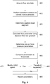
- a rate of rotation of the impeller is shown in Figure 3 .
- the electronic processing device monitors blood flow through the VAD. This could be performed in accordance with signals received from a sensor within the VAD, but more typically is achieved by receiving flow rate data from a ventricular assist device controller or calculating a flow rate based on rotation of a ventricular assist device impeller.
- step 310 the electronic processing device determines if there has been a change in the flow parameter value. If not, no action is required and the process returns to step 300. Otherwise, the process moves to step 320 to determine if the flow parameter value has increased or decreased.
- the electronic processing device increases the speed of impeller rotation at step 330, to thereby increase the flow rate through the pump and hence reduce ventricular filling pressure.
- the speed of impeller rotation is decreased at step 340. Accordingly, it will be appreciated that this process is effectively self-regulating, allowing the speed of impeller rotation to be continually adjusted to thereby ensure that blood pressure within the ventricle is maintained at a desired level. This can therefore automatically accommodate changes in blood pressure that arise from exercising or the like.
- the impeller speed is adjusted based on changes in the flow parameter value. It will be appreciated however that this could also be performed on the basis of the blood pressure parameter value derived from the flow parameter value as these are related by a defined mathematical relationship.
- the electronic processing device can alternatively compare either the flow or blood pressure parameter value to at least one threshold and selectively adjusts blood flow through the ventricular assist device based on the results of the comparison.
- the threshold can be indicative of a nominal range, determined based on a parameter value determined from a sample population or at least in part based on a parameter value previously determined for the subject. Accordingly, in this example, a change in impeller speed would only be performed in the event that certain threshold boundaries are exceeded, such as a certain change in ventricular filling pressure or flow parameter from when the VAD speed was previously changed.
- Other suitable control mechanisms could be used, such as hysteresis control mechanisms, or the like.
- a similar technique could be used to generate a notification, for example to indicate that there is a blood pressure problem, suction event or the like, which can be useful in monitoring patient welfare and operation of the VAD.
- the electronic processing device can also be adapted to record the flow parameter value, display a representation of the flow parameter value, record a blood pressure parameter value or display a representation of the blood pressure parameter value, allowing operation of the VAD and patient wellbeing to be recorded and subsequently reviewed. This can assist in identifying causes of adverse events, and hence taking action to mitigate these in future.
- the blood pressure parameter value typically includes an intra-cardiac pressure, and in particular is usually a ventricular filling pressure, such as a ventricular EDP. It will be appreciated that this value is also typically related or similar to an atrial pressure and a pulmonary capillary wedge pressure (PCWP) during diastole, although this to some extent depends on the patient's heart function, and for example, whether the subject's aortic valve is open, as will be understood by persons skilled in the art. This can in turn be used to derive other pressure parameters including systemic pressures, such as a MAP, using information about heart function.
- the electronic processing device calculates a ventricular filing pressure using the flow parameter value, determines a ventricular assist device power usage and then calculates a mean arterial pressure using the ventricular pressure and the ventricular assist device power usage.
- Head pressure afterload pressure ⁇ preload pressure
- MAP V ⁇ I / Q ⁇ 133.3 ⁇ ⁇ + m . dQ / dt + C
- the pump efficiency losses are typically standard for each pump and accordingly, this allows the MAP to be calculated in real-time from the flow parameter.
- this equation is typically only accurate whilst the aortic valve is closed, and accordingly, the process of determining the MAP will typically include determining whether the aortic valve is closed, which can be achieved using known techniques, and if so using equation (6) to calculate the instantaneous MAP.
- the MAP can be calculated using a combination of the two equations and information regarding the timing of the aortic valve opening and closing.
- the above described arrangement allows blood pressure parameter values to be determined, whilst also allowing operation of the VAD to be controlled to accommodate changes in pressure caused by exercise or the like.
- the electronic processing device acquires flow data indicative of blood flow through the VAD from the VAD controller.
- the electronic processing device performs waveform analysis to identify separate cardiac cycles corresponding to individual heart beats. These are then examined at step 420 in order to identify the portion of the cardiac cycle corresponding to diastole, in a process that will be described in more detail with reference to Figure 5 .
- the flow parameter value is determined based on the gradient of the flow rate against time during the diastolic portion. It will be appreciated that this can be achieved using any suitable approach once the diastolic portion of the flow has been identified, for example by using a linear regression on the flow rate against time curve.
- One or more pressure parameter values are then determined at step 440, for example by using equations (1) to (6) above.
- the electronic processing device compares one or more of the parameters to respective thresholds to determine if the thresholds are exceeded.
- the flow parameter value can be compared to upper and lower limits representing values for which a change in pump speed is warranted.
- the thresholds could be based on fixed values, or alternatively could be relative, for example derived from baseline or other previous flow parameter values measured for the subject. For example, the threshold could be set at ⁇ 10% of the measured flow parameter value for the last flow rate change, with this being used to increase or decrease the pump speed as required. Thus, if the flow parameter value undergoes an increase of 10%, then the pump speed and hence throughput could be increased at step 470.
- the flow and/or pressure parameter values could be recorded at step 480, for example as part of data logging to validate or monitor pump operation, and/or to form part of a patient record, allowing longitudinal tracking of blood pressure parameters.
- the thresholds used for the comparison could be updated, for example if the pump speed has been changed, otherwise the process returns to step 400 allowing the monitoring process to continue.
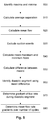
- the waveform analysis is used to determine characteristics such as heart rate, mean flow, mean maximum and minimum flow, and mean peak-to-trough amplitude, as well as detecting gradient of the flow waveform during diastole (diastolic dQ/dt) with a view to predicting the ventricular filling pressure.
- maxima and minima are identified in flow rate data corresponding to a number of heat beats.
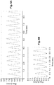
- An example of the flow rate data is shown in Figure 6A , with the maxima and minima being shown in Figure 6B .
- an average separation between the maxima and minima is calculated, with the mean flow rate being determined at step 520. It will be appreciated that this can be achieved using standard processing techniques and will not therefore be described in detail.
- suction events are removed, as will be described in more detail with reference to Figure 7 , as the suction events can unduly effect the calculation of flow rate.
- mean maximum and minimum flow rates are calculated, with the difference between the means being determined at step 550.
- the diastolic segment of each heat beat is determined using the difference between the means.
- diastole is defined as the period between the point of least flow and the point halfway to maximum flow, as shown in Figure 6C , although other assessment criteria could be used.
- the gradient of the flow during diastole is determined, for example by fitting a line to the flow rate data using the method of least squares to determine the diastolic flow rate gradient dQ/dt. This can then be used to determine a mean flow rate gradient over a number of cycles at step 580, which represents the flow parameter value.
- the gradient during diastole could be measured between different end points, such as from a minimum flow to a point quarter way to maximum flow, as shown in Figure 6D .
- the gradient is designated ndQ/dt, merely to distinguish this from the gradient dQ/dt shown in Figure 6C .
- this is not intended to be limiting and in practice these measures can be used interchangeably as the gradient, and other measures of gradient could be used. Nevertheless, it has been shown that use of ndQ/dt can be more accurate than dQ/dt in some circumstances, as will be discussed in more detail below.
- minima are divided into two clusters.
- K-means clustering partitions observations into k clusters where each observation belongs to the cluster with the nearest mean or "centroid".
- step 710 it is determined if the centroids of each cluster are separated by less than two standard deviations, in which case at step 720 the clustering is ignored and suction beats are defined as those more than two standard deviations below the mean, at step 730. This process is used to eliminate occasional suction beats as shown in Figure 8A .
- step 740 it is determined if the centroids of each cluster are separated by more than two standard deviations, in which case clustering continues at step 750, with suction beats being defined as minima in the cluster with the smaller centroid, which is used to eliminate distinct populations of beats, as shown in Figure 8B .
- RHC right atrial pressure
- MPAP mean pulmonary arterial pressure
- PCWP mean pulmonary arterial pressure
- SvO 2 mixed venous oxygen saturation
- CCO Continuous cardiac output
- LVAD parameters speed, power and flow were recorded from the HeartWare monitor.
- Left ventricular end systolic (LVESD) and diastolic dimensions (LVEDD) were also noted. These parameters were recorded at each stage of speed titration and exercise. Blood samples were also taken immediately pre- and post-exercise to determine B-type natriuretic peptide (BNP), lactate dehydrogenase (LDH) and lactate levels.
- BNP B-type natriuretic peptide
- LDH lactate dehydrogenase
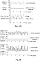
- Example waveforms for patients with atrial fibrillation and bigeminy are shown in Figures 9A and 9B . These highlight how flow rate during systole varies significantly between different beats, resulting from different systolic ventricular pressure as a result of the fibrillation or bigeminy, in turn highlighting how the blood flow through the VAD is influenced by the patient's cardiac rhythm. It will be noted that the flow rate gradients during diastole remain relatively constant, highlighting that these values can be used to derive flow and blood pressure parameters even in patients suffering from these conditions, which typically would not be expected to have a major impact on ventricular filling pressure.
- Figures 9C and 9D highlight how exercise causes an increase in the flow rate gradient during diastole, corresponding to an increase in ventricular filling pressure.
- Figures 9E and 9F show the effect of increasing pump speed during exercise, and in particular, that this can be used to reduce the flow rate gradient and hence ventricular filling pressure during diastole. Thus, this shows in broad terms how the flow rate gradient tracks expected ventricular filling pressure and that additionally an increase in pump speed is effect at counteracting the increased ventricular filling pressure resulting from exercise.
- the relationship between measured PCWP and diastolic flow rate gradient (dQ/dt) was analysed using linear mixed effects regression, controlling for heart rate, MAP and mean flow as a covariates.
- the mixed-effects model accounted for repeated measures within subjects by assuming each patient had their own unique response trajectory with a random intercept and slope. Parameters were estimated by maximum likelihood. Log-likelihood ratio tests were carried out to determine whether a random intercept model, a random slope model or a random intercept and slope model was necessary, however the tests were not significant and therefore analysis proceeded with stepwise multiple linear regression on the grounds of parsimony.
- Stepwise multiple linear regression of diastolic dQ/dt with PCWP, heart rate, MAP and mean flow as predictor variables was used to assess what variables contribute to this novel parameter and identify potential confounders.
- Results are presented as median (range) or mean ⁇ standard deviation unless otherwise specified. A p-value of 0.05 was considered statistically significant.
- Table 1 shows heart rate, mean arterial pressure, central haemodynamic measures, mixed venous oxygen saturation and left ventricular dimensions during the rest, light and peak exercise performed at baseline and maximum pump speeds
- Table 2 shows changes in heart rate, mean arterial pressure, central haemodynamic measures and mixed venous oxygen saturation from baseline to maximum speed in individual patients performing peak exercise.
- Table 1 Rest Light Exercise Peak Exercise Baselin e Speed Baselin e Speed Max. Spee P Baselin e Speed Max.
- HR heart rate
- MAP mean arterial pressure
- CCO continuous cardiac output
- RAP right atrial pressure
- MPAP mean pulmonary arterial pressure
- PCWP pulmonary capillary wedge pressure
- SvO2 mixed venous oxygen saturation
- LVEDD left ventricular end diastolic dimension
- LVESD left ventricular end systolic dimension.
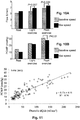
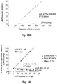
- the relationship between diastolic dQ/dt and PCWP is illustrated in Figure 11 .
- the study demonstrates an increase in flow with maximum pump speed over baseline speed during peak exercise.
- pump flow through a cfLVAD is influenced by a variety of factors, including pump speed and head pressure.
- the head pressure corresponds to the difference between the aortic pressure and left ventricular pressure, with an increase in preload or a decrease in afterload resulting in an increase in flow.
- the spontaneous increase in pump flow from rest to exercise, regardless of speed adjustment is largely attributed to an increase in venous return and preload. However, this does not account for the greater flows at higher pump speeds. As speed is increased, greater unloading of the left ventricle results in reduced preload and a higher head pressure, yet pump flow remains increased.
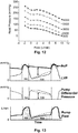
- Figure 12 illustrates the relationship between head pressure and flow at different pump speeds for the HeartWare HVAD. Higher pump speeds are able to generate the same amount of flow at substantially greater head pressures. Additionally the H-Q curve for the HeartWare HVAD is relatively flat which means that large fluctuations in flow occur for small changes in head pressure. Changes in pressure caused by native heart contractions therefore result in remarkably pulsatile flow through the HVAD, despite the classification of the pump as a cfLVAD.
- the diastolic flow rate gradient dQ/dt correlates with PCWP, which in turn provides an estimate of ventricular filling pressure and in particular left ventricular end-diastolic pressure.
- PCWP which in turn provides an estimate of ventricular filling pressure and in particular left ventricular end-diastolic pressure.
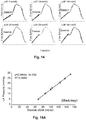
- Figure 16 shows how variation in LAP leads to a change in the diastolic flow rate gradient, the systolic flow rate gradient and mean flow rate, again demonstrating good correlation with the diastolic flow rate gradient.
- Figure 17 is a graph showing the measured MAP compared to a derived MAP determined from the flow parameter value using equation (6) above, again demonstrating a high degree of correlation.
- Figures 18A to 18D show graphs of measured and derived blood pressure parameter values over a number of cardiac cycles in the mock circulation loop.
- Figures 18A and 18C include comparison of measured, derived and smoothed aortic pressure, as well as a comparison of measured LAP and derived EDP corresponding to the ventricular filling pressure, again showing good correlation, whilst Figures 18B and 18D show corresponding power, flow and EDP used in calculating the MAP.
- the above described techniques can therefore be used to determine a flow parameter value, and in particular a flow rate gradient during diastole, which can in turn be used to control a VAD and determine blood pressure parameter values including a ventricular filling pressure, and in particular an EDP, with this in turn being used in conjunction with VAD operating parameters to calculate a MAP.
- the flow parameter value and/or pressure parameter value can also be used to control the VAD and in particular increase the VAD speed in response to an increase in flow rate gradient or blood pressure parameter, thereby increasing flow through the VAD and returning the ventricular filling pressure to a normal level.
- dQ/dt and in particular the use of the time period between minimum flow and half maximum flow is not intended to be limiting when calculating the gradient.
- a comparative analysis was performed between dQ/dt and ndQ/dt.
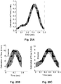
- ndQdt encompasses only an early portion of the diastolic flow, specifically between minimum flow and half maximum flow. Examination of data collected from a mock circulation loop shows that certain diastolic flow portions exhibit a plateau before the systolic portion, thus reducing the gradient measured using dQdt. Secondly, the measure dQdt infrequently included parts of the systolic flow waveform, thus markedly increasing the gradient measured. Examples of this are shown in Figures 20A to 20C .
- a plateau in flow rate towards the end of diastole is shown in Figure 20A .
- the use of a first time period, corresponding to the point of lowest flow to half flow, and resulting inclusion of systole within the dQ/dt calculation of gradient is shown in Figure 20B , highlighting significant variation in gradient values.
- a second shorter time period is used to calculate ndQ/dt, thereby exclude any plateau and systole, leading to greater consistency in gradient values.
- ndQ/dt is highly correlated with surrogate measurements of preload, LAP and PCWP in both a mock circulation loop and cfLVAD patients respectively. Additionally, results show ndQ/dt to be very robust in the mock circulation loop, with changes in haematocrit, AoP and HR having no effect on the efficacy of ndQ/dt as a measure of pressure. Changes in LVAD speed also have a negligible impact, individually accounting for only 0.4% of the variance in ndQ/dt. This finding was confirmed in patient studies where HR and LVAD speed were not found to influence ndQ/dt, meaning that the measure ndQ/dt can be used in a wide range of clinical scenarios. In contrast, dQ/dt whilst accurate in most cases, is influenced by HR, possibly due to portions of systolic waveform being included at higher HR, thus artificially increasing dQ/dt.
- both ndQ/dt and dQ/dt demonstrated a strong ability to detect elevated or reduced preload, with an AUC (Area Under Curve) over 0.97 in the mock circulation loop using ndQ/dt and AUC over 0.85 in vivo using either ndQ/dt or dQ/dt.
- AUC Absolute Under Curve
- Having a robust, continuous marker of elevated preload allows clinicians to determine the potential need to offload the left ventricle, either through increasing pump speed or by using diuretics, without the need for invasive right heart catheterization. Furthermore, a warning that preload was reduced could assist clinicians in reducing the risk of ventricular suction and over-pumping and could be integrated into physiological pump controllers.
- the above described techniques therefore allow for successful estimation of LAP and PCWP, as surrogates for preload, in both in vitro and in vivo settings from HVAD flow waveform analysis.
- This also allows for the estimation of mean arterial pressure and head pressure using only HVAD pump parameters, which in turn allows for continuous non-invasive estimation of blood pressure in patients with HVADs.
- both ndQ/dt and dQ/dt demonstrated a strong ability to detect elevated or reduced preload, with an AUC (Area Under Curve) over 0.97 in the mock circulation loop using ndQ/dt and AUC over 0.85 in vivo using either ndQ/dt or dQ/dt.
- AUC Absolute Under Curve
- Having a robust, continuous marker of elevated preload allows clinicians to determine the potential need to offload the left ventricle, either through increasing pump speed or by using diuretics, without the need for invasive right heart catheterization. Furthermore, a warning that preload was reduced could assist clinicians in reducing the risk of ventricular suction and over-pumping and could be integrated into physiological pump controllers.
- the above described techniques therefore allow for successful estimation of LAP and PCWP, as surrogates for preload, in both in vitro and in vivo settings from HVAD flow waveform analysis.
- This also allows for the estimation of mean arterial pressure and head pressure using only HVAD pump parameters, which in turn allows for continuous non-invasive estimation of blood pressure in patients with HVADs.
Landscapes
- Health & Medical Sciences (AREA)
- Heart & Thoracic Surgery (AREA)
- Engineering & Computer Science (AREA)
- Cardiology (AREA)
- Hematology (AREA)
- Mechanical Engineering (AREA)
- Anesthesiology (AREA)
- Biomedical Technology (AREA)
- Life Sciences & Earth Sciences (AREA)
- Animal Behavior & Ethology (AREA)
- General Health & Medical Sciences (AREA)
- Public Health (AREA)
- Veterinary Medicine (AREA)
- Vascular Medicine (AREA)
- Medical Informatics (AREA)
- External Artificial Organs (AREA)
- Measuring Pulse, Heart Rate, Blood Pressure Or Blood Flow (AREA)
Claims (14)
- Appareil pour utilisation avec un dispositif d'assistance ventriculaire (120) qui, lorsqu'il est en cours d'utilisation, assiste la fonction cardiaque d'un sujet biologique, l'appareil comprenant un dispositif de traitement électronique (101) qui, lorsqu'il est en cours d'utilisation :a) détermine un débit de sang à travers le dispositif d'assistance ventriculaire ;b) analyse le débit pour déterminer une valeur de paramètre de débit au moins partiellement indicative d'un changement du débit pendant une diastole ; et,c) utilise la valeur de paramètre de débit pour effectuer au moins l'une des actions suivantes :i) déduire au moins une valeur de paramètre de pression artérielle au moins partiellement indicative d'une pression artérielle chez le sujet biologique ; etii) contrôler le dispositif d'assistance ventriculaire, caractérisé en ce que la valeur de paramètre de débit est indicative d'un gradient de débit pendant la diastole.
- Appareil selon la revendication 1, dans lequel le dispositif de traitement électronique (101), lorsqu'il est en cours d'utilisation :a) compare une valeur de paramètre à au moins un seuil, la valeur de paramètre étant au moins l'une parmi la valeur de paramètre de débit et une valeur de paramètre de pression artérielle et le seuil étant éventuellement au moins l'un parmi :i) indicatif d'une plage nominale ;ii) déterminé sur la base d'une valeur de paramètre déterminée à partir d'une population d'échantillons ; et,iii) au moins en partie basé sur une valeur de paramètre précédemment déterminée pour le sujet ; et,b) en réponse aux résultats de la comparaison, effectue au moins l'une des actions suivantes :i) ajuste sélectivement le débit sanguin à travers le dispositif d'assistance ventriculaire (120) ; etii) génère sélectivement une notification.
- Appareil selon la revendication 1 ou la revendication 2, dans lequel le dispositif d'assistance ventriculaire (120) comprend une turbine rotative, et dans lequel le dispositif de traitement électronique, lorsqu'il est en cours d'utilisation, contrôle le débit sanguin à travers le dispositif d'assistance ventriculaire en amenant une vitesse de rotation de la turbine à être ajustée.
- Appareil selon l'une quelconque des revendications 1 à 3, dans lequel le dispositif de traitement électronique (101), lorsqu'il est en cours d'utilisation :a) détermine le débit sur au moins un cycle cardiaque ; et,b) analyse le débit, éventuellement au moyen d'une analyse de forme d'onde, pour identifier une période du cycle cardiaque correspondant à une diastole ;c) détermine le gradient de débit pendant la période de diastole ; et,d) détermine la valeur de paramètre de débit au moyen du gradient de débit.
- Appareil selon la revendication 4, dans lequel le dispositif de traitement électronique (101), lorsqu'il est en cours d'utilisation :a) analyse le débit sur une pluralité de cycles cardiaques ;b) détermine un gradient de débit moyen pendant une diastole ; et,c) détermine la valeur de paramètre de débit au moyen d'un gradient de débit moyen.
- Appareil selon la revendication 5, dans lequel le dispositif de traitement électronique (101), lorsqu'il est en cours d'utilisation :a) calcule des maximums et des minimums de débit pour chacun de la pluralité de cycles cardiaques ; et,b) exclut sélectivement un cycle cardiaque sur la base d'au moins l'un parmi :i) les maximums de débit respectifs du cycle cardiaque ;ii) les minimums de débit respectifs du cycle cardiaque ; et,iii) des cycles cardiaques correspondant à des événements d'aspiration.
- Appareil selon la revendication 5 ou la revendication 6, dans lequel le dispositif de traitement électronique (101), lorsqu'il est en cours d'utilisation :a) calcule des maximums et des minimums de débit pour chacun de la pluralité de cycles cardiaques ; et,b) détermine une période du cycle cardiaque correspondant à une diastole au moyen des maximums et des minimums de débit.
- Appareil selon la revendication 7, dans lequel le dispositif de traitement électronique (101), lorsqu'il est en cours d'utilisation, détermine la diastole comme étant une période du cycle cardiaque des minimums de débit à une proportion des maximums de débit et dans lequel la proportion des maximums de débit est au moins l'une parmi :a) la moitié des maximums de débit ; et,b) le quart des maximums de débit.
- Appareil selon l'une quelconque des revendications 1 à 8, dans lequel le dispositif de traitement électronique (101), lorsqu'il est en cours d'utilisation, effectue au moins l'une des actions suivantes :a) enregistre la valeur de paramètre de débit ;b) affiche une représentation de la valeur de paramètre de débit ;c) enregistre une valeur de paramètre de pression artérielle ; et,d) affiche une représentation de la valeur de paramètre de pression artérielle.
- Appareil selon l'une quelconque des revendications 1 à 9, dans lequel l'au moins une valeur de paramètre de pression artérielle est au moins partiellement indicative d'au moins l'un parmi :a) une pression intracardiaque ;b) une pression auriculaire ;c) une pression de remplissage ventriculaire ;d) une pression capillaire pulmonaire ;e) une pression télédiastolique ventriculaire ; et,f) une pression artérielle moyenne.
- Appareil selon l'une quelconque des revendications 1 à 10, dans lequel le dispositif de traitement électronique (101), lorsqu'il est en cours d'utilisation :a) calcule une pression de remplissage ventriculaire utilisant la valeur de paramètre de débit ;b) détermine une consommation électrique du dispositif d'assistance ventriculaire ; et,c) calcule une pression artérielle moyenne au moyen de la pression de remplissage ventriculaire et de la consommation électrique du dispositif d'assistance ventriculaire.
- Appareil selon l'une quelconque des revendications 1 à 11, dans lequel le dispositif de traitement électronique (101) est au moins l'un parmi :a) au moins une partie d'un dispositif de contrôle de dispositif d'assistance ventriculaire ; et,b) couplé à un dispositif de contrôle de dispositif d'assistance ventriculaire (110).
- Appareil selon l'une quelconque des revendications 1 à 12, dans lequel le dispositif de traitement électronique (101), lorsqu'il est en cours d'utilisation, détermine le débit sanguin selon au moins une des façons suivantes :a) en fonction de signaux reçus depuis un capteur ;b) par réception de données de débit depuis un dispositif de contrôle de dispositif d'assistance ventriculaire ; et,c) par calcul d'un débit sur la base de la rotation d'une turbine de dispositif d'assistance ventriculaire.
- Procédé d'utilisation d'un dispositif d'assistance ventriculaire qui assiste la fonction cardiaque d'un sujet biologique, le procédé comprenant :a) la détermination d'un débit de sang à travers le dispositif d'assistance ventriculaire (120) ;b) l'analyse du débit pour déterminer une valeur de paramètre de débit au moins partiellement indicative d'un changement du débit pendant la diastole ; et,c) l'utilisation de la valeur de paramètre de débit pour déduire au moins une valeur de paramètre de pression artérielle au moins partiellement indicative d'une pression artérielle chez le sujet biologique, caractérisé en ce que la valeur de paramètre de débit est indicative d'un gradient de débit pendant la diastole.
Applications Claiming Priority (2)
| Application Number | Priority Date | Filing Date | Title |
|---|---|---|---|
| AU2014902046A AU2014902046A0 (en) | 2014-05-29 | Ventricular assist device method and apparatus | |
| PCT/AU2015/050288 WO2015179921A1 (fr) | 2014-05-29 | 2015-05-28 | Méthode et appareil de dispositif d'assistance ventriculaire |
Publications (3)
| Publication Number | Publication Date |
|---|---|
| EP3148604A1 EP3148604A1 (fr) | 2017-04-05 |
| EP3148604A4 EP3148604A4 (fr) | 2018-02-07 |
| EP3148604B1 true EP3148604B1 (fr) | 2020-09-30 |
Family
ID=54697735
Family Applications (1)
| Application Number | Title | Priority Date | Filing Date |
|---|---|---|---|
| EP15799117.5A Active EP3148604B1 (fr) | 2014-05-29 | 2015-05-28 | Méthode et appareil de dispositif d'assistance ventriculaire |
Country Status (6)
| Country | Link |
|---|---|
| US (1) | US10610627B2 (fr) |
| EP (1) | EP3148604B1 (fr) |
| JP (1) | JP6616405B2 (fr) |
| AU (1) | AU2015268105B2 (fr) |
| CA (1) | CA2950310C (fr) |
| WO (1) | WO2015179921A1 (fr) |
Families Citing this family (54)
| Publication number | Priority date | Publication date | Assignee | Title |
|---|---|---|---|---|
| US20160166211A1 (en) * | 2014-12-02 | 2016-06-16 | Heartware, Inc. | Mean arterial pressure estimation |
| WO2017156386A1 (fr) * | 2016-03-10 | 2017-09-14 | The University Of Chicago | Pente de phase de remplissage ventriculaire utilisée comme indicateur de pression capillaire pulmonaire élevée et/ou d'index cardiaque |
| EP3431120B1 (fr) * | 2016-03-17 | 2024-10-30 | Terumo Kabushiki Kaisha | Dispositif de gestion de circulation extracorporelle, dispositif de circulation extracorporelle et programme de gestion de circulation extracorporelle |
| ES2754405T3 (es) | 2016-08-23 | 2020-04-17 | Abiomed Europe Gmbh | Dispositivo de asistencia ventricular |
| US11033727B2 (en) * | 2016-11-23 | 2021-06-15 | Magenta Medical Ltd. | Blood pumps |
| DK3570739T3 (da) * | 2017-01-19 | 2025-03-24 | HighDim GmbH | Indretninger og fremgangsmåder til at bestemme hjertefunktionen hos en levende person |
| EP3634528B1 (fr) | 2017-06-07 | 2023-06-07 | Shifamed Holdings, LLC | Dispositifs de déplacement de fluide intravasculaire, systèmes et procédés d'utilisation |
| DK3634526T3 (da) | 2017-06-09 | 2024-03-11 | Abiomed Inc | Bestemmelse af hjerteparametre til modulation af blodpumpestøtte |
| US11511103B2 (en) | 2017-11-13 | 2022-11-29 | Shifamed Holdings, Llc | Intravascular fluid movement devices, systems, and methods of use |
| EP3727492B1 (fr) | 2017-12-19 | 2025-01-29 | Boston Scientific Scimed, Inc. | Mesure de la fréquence cardiaque utilisant la position d'un impulseur de pompe à sang |
| EP3746149B1 (fr) | 2018-02-01 | 2025-08-06 | Shifamed Holdings, LLC | Pompes à sang intravasculaires |
| US11235139B2 (en) | 2018-05-17 | 2022-02-01 | Heartware, Inc. | Current-speed relationship for instantaneous suction detection algorithm in LVADS |
| DE102018208538A1 (de) | 2018-05-30 | 2019-12-05 | Kardion Gmbh | Intravasale Blutpumpe und Verfahren zur Herstellung von elektrischen Leiterbahnen |
| DE102018208933A1 (de) | 2018-06-06 | 2019-12-12 | Kardion Gmbh | Verfahren zur Bestimmung einer Strömungsgeschwindigkeit eines durch ein implantiertes, vaskuläres Unterstützungssystem strömenden Fluids |
| DE102018208870A1 (de) | 2018-06-06 | 2019-12-12 | Kardion Gmbh | Verfahren zur Bestimmung eines Fluid-Volumenstroms durch ein implantiertes, vaskuläres Unterstützungssystem |
| DE102018208945A1 (de) | 2018-06-06 | 2019-12-12 | Kardion Gmbh | Analysevorrichtung und Verfahren zum Analysieren einer Viskosität eines Fluids |
| DE102018208936A1 (de) | 2018-06-06 | 2019-12-12 | Kardion Gmbh | Bestimmvorrichtung und Verfahren zum Bestimmen einer Viskosität eines Fluids |
| DE102018208929A1 (de) | 2018-06-06 | 2019-12-12 | Kardion Gmbh | Verfahren zur Bestimmung einer Strömungsgeschwindigkeit eines durch ein implantiertes, vaskuläres Unterstützungssystem strömenden Fluids |
| DE102018208899A1 (de) | 2018-06-06 | 2019-12-12 | Kardion Gmbh | Verfahren zum Ermitteln der Schallgeschwindigkeit in einem Fluid im Bereich eines implantierten, vaskulären Unterstützungssystems |
| DE102018208913A1 (de) | 2018-06-06 | 2019-12-12 | Kardion Gmbh | Verfahren zum Betreiben eines implantierten, ventrikulären Unterstützungssystems |
| DE102018208879A1 (de) | 2018-06-06 | 2020-01-30 | Kardion Gmbh | Verfahren zur Bestimmung eines Fluid-Gesamtvolumenstroms im Bereich eines implantierten, vaskuläres Unterstützungssystems |
| DE102018208931A1 (de) | 2018-06-06 | 2019-12-12 | Kardion Gmbh | Vorrichtung zum Bestimmen eines Herzzeitvolumens für ein Herzunterstützungssystem, Herzunterstützungssystem und Verfahren zum Bestimmen eines Herzzeitvolumens |
| DE102018208862A1 (de) | 2018-06-06 | 2019-12-12 | Kardion Gmbh | Implantierbares, vaskuläres Unterstützungssystem |
| DE102018208892A1 (de) | 2018-06-06 | 2019-12-12 | Kardion Gmbh | Sensorkopfvorrichtung für ein minimalinvasives Herzunterstützungssystem und Verfahren zum Herstellen einer Sensorkopfvorrichtung für ein Herzunterstützungssystem |
| EP3581216A1 (fr) * | 2018-06-11 | 2019-12-18 | Universität Zürich | Pompe sanguine pour l'assistance circulatoire mécanique des patients opérés d'un fontan |
| NZ771868A (en) * | 2018-06-19 | 2025-08-29 | Massachusetts Inst Technology | Systems and methods for system identification |
| DE102018210076A1 (de) | 2018-06-21 | 2019-12-24 | Kardion Gmbh | Verfahren und Vorrichtung zum Erkennen eines Verschleißzustands eines Herzunterstützungssystems, Verfahren und Vorrichtung zum Betreiben eines Herzunterstützungssystems und Herzunterstützungssystem |
| WO2020028537A1 (fr) | 2018-07-31 | 2020-02-06 | Shifamed Holdings, Llc | Pompes sanguines intravasculaires et procédés d'utilisation |
| US10960118B2 (en) | 2018-07-31 | 2021-03-30 | Abiomed, Inc. | Systems and methods for controlling a heart pump to minimize myocardial oxygen consumption |
| DE102018213350A1 (de) | 2018-08-08 | 2020-02-13 | Kardion Gmbh | Vorrichtung und Verfahren zur Überwachung eines Gesundheitszustands des Patienten |
| WO2020068333A1 (fr) * | 2018-09-25 | 2020-04-02 | Tc1 Llc | Algorithmes de commande de vitesse adaptative et dispositifs de commande d'optimisation de débit dans des dispositifs d'assistance ventriculaire |
| EP3856275B1 (fr) * | 2018-09-27 | 2023-01-18 | Heartware, Inc. | Estimation de la pam sur des patients équipés d'un dav |
| WO2020073047A1 (fr) | 2018-10-05 | 2020-04-09 | Shifamed Holdings, Llc | Pompes à sang intravasculaires et procédés d'utilisation |
| WO2020093084A1 (fr) * | 2018-11-09 | 2020-05-14 | St Vincent's Hospital Sydney Limited | Détermination de fonction ventriculaire |
| WO2020154638A1 (fr) | 2019-01-25 | 2020-07-30 | Transonic Systems, Inc. | Procédé et appareil pour évaluer un débit cardiaque dans une oxygénation sanguine veino-veineuse extracorporelle |
| WO2020160138A1 (fr) | 2019-01-29 | 2020-08-06 | Transonic Systems, Inc. | Procédé et appareil pour évaluer une sortie cardiaque dans une oxygénation sanguine extracorporelle veno-artérielle |
| US11666281B2 (en) | 2019-02-28 | 2023-06-06 | Medtronic, Inc. | Detection of hypertension in LVAD patients using speed change |
| EP4566535A3 (fr) * | 2019-05-02 | 2025-06-25 | Transonic Systems Inc. | Calcul du débit cardiaque d'un patient subissant une oxygénation sanguine extracorporelle veno-veineuse |
| WO2021011473A1 (fr) | 2019-07-12 | 2021-01-21 | Shifamed Holdings, Llc | Pompes à sang intravasculaires et méthode d'utilisation et procédé de fabrication |
| US11654275B2 (en) | 2019-07-22 | 2023-05-23 | Shifamed Holdings, Llc | Intravascular blood pumps with struts and methods of use and manufacture |
| US12465748B2 (en) | 2019-08-07 | 2025-11-11 | Supira Medical, Inc. | Catheter blood pumps and collapsible pump housings |
| US11724089B2 (en) | 2019-09-25 | 2023-08-15 | Shifamed Holdings, Llc | Intravascular blood pump systems and methods of use and control thereof |
| EP4501393A3 (fr) | 2019-09-25 | 2025-04-09 | Shifamed Holdings, LLC | Pompes à sang à cathéter et boîtiers de pompes pliables |
| WO2021062260A1 (fr) | 2019-09-25 | 2021-04-01 | Shifamed Holdings, Llc | Pompes à sang de cathéter et conduits sanguins pliables |
| EP4072650A4 (fr) | 2019-12-11 | 2024-01-10 | Shifamed Holdings, LLC | Pompes à sang d'aorte descendante et de veine cave |
| US20210178037A1 (en) * | 2019-12-16 | 2021-06-17 | Medtronic, Inc. | Intra-ventricular pulsatile assist system (iv-pas) |
| EP4077947A4 (fr) | 2019-12-19 | 2024-01-10 | Shifamed Holdings, LLC | Pompes à sang intravasculaires, moteurs et commande de fluide |
| US20220031256A1 (en) * | 2020-07-31 | 2022-02-03 | 3M Innovative Properties Company | Composite phonocardiogram visualization on an electronic stethoscope display |
| US11707600B2 (en) * | 2020-11-18 | 2023-07-25 | CardioDriven, Inc. | Level set calibration and assurance for pulmonary artery pressure catheterization |
| US12502524B2 (en) | 2021-12-03 | 2025-12-23 | Kardion Gmbh | Cardiac pump with optical fiber for laser doppler |
| CN114947781B (zh) * | 2022-05-12 | 2026-03-17 | 遵义医科大学附属医院 | 一种bpm参数自适应的人工心脏 |
| CN115645736B (zh) * | 2022-11-11 | 2024-03-26 | 上海焕擎医疗科技有限公司 | 控制装置、心室辅助系统、动态控制方法、设备及可读介质 |
| CN116870357B (zh) * | 2023-07-10 | 2024-03-08 | 上海玮启医疗器械有限公司 | 一种智能左心室辅助系统 |
| CN116943015B (zh) * | 2023-09-21 | 2023-12-15 | 安徽通灵仿生科技有限公司 | 一种心室辅助设备的控制方法及装置 |
Family Cites Families (35)
| Publication number | Priority date | Publication date | Assignee | Title |
|---|---|---|---|---|
| US4811184A (en) | 1988-05-10 | 1989-03-07 | General Electric Company | Switch-mode power supply with dynamic adjustment of current sense magnitude |
| US5066900A (en) | 1989-11-14 | 1991-11-19 | Computer Products, Inc. | Dc/dc converter switching at zero voltage |
| US6783328B2 (en) * | 1996-09-30 | 2004-08-31 | Terumo Cardiovascular Systems Corporation | Method and apparatus for controlling fluid pumps |
| US5888242A (en) | 1996-11-01 | 1999-03-30 | Nimbus, Inc. | Speed control system for implanted blood pumps |
| US6278279B1 (en) | 1998-08-28 | 2001-08-21 | International Business Machines Corporation | Path test for a DC battery back-up system |
| US6198611B1 (en) | 1998-12-15 | 2001-03-06 | Pass & Seymour, Inc. | Arc fault circuit interrupter without DC supply |
| CZ305727B6 (cs) * | 2000-03-27 | 2016-02-24 | The Cleveland Clinic Foundation | Pomocný přístroj pro pacienty s onemocněním srdce a způsob řízení průtoku krve krevní pumpou |
| US6504692B1 (en) | 2000-04-06 | 2003-01-07 | Pass & Seymour, Inc. | AFCI device which detects upstream and downstream series and parallel ARC faults |
| JP4674978B2 (ja) * | 2001-02-01 | 2011-04-20 | Cyberdyne株式会社 | 心機能評価装置 |
| CA2472621A1 (fr) * | 2002-01-07 | 2003-07-17 | Micromed Technology, Inc. | Procede et systeme de regulation physiologique d'une pompe a sang implantable |
| US20040015294A1 (en) * | 2002-07-20 | 2004-01-22 | Kirtland Kenneth P. | Computerized warning system interface and method |
| US6949066B2 (en) | 2002-08-21 | 2005-09-27 | World Heart Corporation | Rotary blood pump diagnostics and cardiac output controller |
| US7494459B2 (en) * | 2003-06-26 | 2009-02-24 | Biophan Technologies, Inc. | Sensor-equipped and algorithm-controlled direct mechanical ventricular assist device |
| US7591777B2 (en) | 2004-05-25 | 2009-09-22 | Heartware Inc. | Sensorless flow estimation for implanted ventricle assist device |
| DE102005030907B4 (de) | 2005-06-30 | 2012-01-12 | Pairan Gmbh | Solargeneratoranlage, Multistrangwechselrichter für Solargeneratoranlagen und Verfahren zum Überprüfen der Isolationswiderstände der Solargeneratorstränge |
| KR100703927B1 (ko) | 2005-10-31 | 2007-04-06 | 한국전력공사 | 이중화 전원용 블로킹다이오드의 고장 감시 장치 |
| US8860377B2 (en) | 2006-02-09 | 2014-10-14 | Karl F. Scheucher | Scalable intelligent power supply system and method |
| US7489138B2 (en) | 2006-11-30 | 2009-02-10 | Honeywell International Inc. | Differential arc fault detection |
| DE102007007198A1 (de) * | 2007-02-09 | 2008-08-14 | Maquet Cardiopulmonary Ag | Verfahren und Vorrichtung zur Überwachung und Optimierung eines durch eine Pumpe bewirkten Blutkreislaufs |
| CN101678160A (zh) * | 2007-04-05 | 2010-03-24 | 麦克罗美德技术公司 | 血泵系统 |
| JP5250866B2 (ja) * | 2008-06-11 | 2013-07-31 | 株式会社サンメディカル技術研究所 | 人工心臓制御装置及び人工心臓システム |
| WO2010039876A1 (fr) | 2008-09-30 | 2010-04-08 | Ihc Intellectual Asset Management, Llc | Détermination d’une caractéristique physiologique pour l’utilisateur d’un dispositif médical |
| US20110210611A1 (en) | 2008-10-10 | 2011-09-01 | Ampt, Llc | Novel Solar Power Circuits |
| US20100121133A1 (en) * | 2008-11-07 | 2010-05-13 | Schumer Douglas B | Apparatus and methods for measuring pressure and flow in cardiac assist devices and peripheral vasculature |
| AU2011201247B2 (en) | 2010-03-24 | 2015-06-11 | Leomon Pty Ltd | Grid connectable inverter with ripple control signal rejection |
| GB2496140B (en) | 2011-11-01 | 2016-05-04 | Solarcity Corp | Photovoltaic power conditioning units |
| US8547669B2 (en) | 2011-01-12 | 2013-10-01 | Schneider Electric USA, Inc. | Arc fault mitigation for photovoltaic systems |
| US9366714B2 (en) | 2011-01-21 | 2016-06-14 | Ampt, Llc | Abnormality detection architecture and methods for photovoltaic systems |
| GB201108963D0 (en) | 2011-05-27 | 2011-07-13 | 3M Innovative Properties Co | Composite materials comprising polyamides and fluoroelastomers |
| DE102011106142A1 (de) | 2011-06-10 | 2012-12-27 | Rheinisch-Westfälische Technische Hochschule Aachen | Blutentnahmekanüle einer die Herzfunktion ersetzenden oder unterstützenden Pumpe |
| WO2013184932A1 (fr) | 2012-06-06 | 2013-12-12 | Heartware, Inc. | Algorithme de modification de vitesse pour une pompe à sang à écoulement continu |
| US20150174307A1 (en) | 2012-07-19 | 2015-06-25 | Regents Of The University Of Minnesota | Cardiac assist device with pulse wave analysis |
| AU2012390067B2 (en) | 2012-09-21 | 2017-11-02 | Reinheart Gmbh | Method of controlling the speed of an ventricular assist device (VAD) and ventricular assist device. |
| EP2851100A1 (fr) | 2013-09-20 | 2015-03-25 | Berlin Heart GmbH | Système de commande de pompe sanguine et procédé pour commander une pompe sanguine |
| WO2016044889A2 (fr) | 2014-09-23 | 2016-03-31 | St Vincent's Hospital (Sydney) Limited | Procédé et appareil pour déterminer une ouverture de valvule aortique |
-
2015
- 2015-05-28 AU AU2015268105A patent/AU2015268105B2/en active Active
- 2015-05-28 US US15/314,088 patent/US10610627B2/en active Active
- 2015-05-28 JP JP2017514739A patent/JP6616405B2/ja not_active Expired - Fee Related
- 2015-05-28 CA CA2950310A patent/CA2950310C/fr active Active
- 2015-05-28 WO PCT/AU2015/050288 patent/WO2015179921A1/fr not_active Ceased
- 2015-05-28 EP EP15799117.5A patent/EP3148604B1/fr active Active
Non-Patent Citations (1)
| Title |
|---|
| None * |
Also Published As
| Publication number | Publication date |
|---|---|
| CA2950310C (fr) | 2022-07-19 |
| US20170239407A1 (en) | 2017-08-24 |
| AU2015268105A1 (en) | 2016-12-15 |
| CA2950310A1 (fr) | 2015-12-03 |
| EP3148604A1 (fr) | 2017-04-05 |
| JP2017522147A (ja) | 2017-08-10 |
| JP6616405B2 (ja) | 2019-12-04 |
| EP3148604A4 (fr) | 2018-02-07 |
| US10610627B2 (en) | 2020-04-07 |
| WO2015179921A1 (fr) | 2015-12-03 |
| AU2015268105B2 (en) | 2019-12-12 |
Similar Documents
| Publication | Publication Date | Title |
|---|---|---|
| US10610627B2 (en) | Ventricular assist device method and apparatus | |
| US12478266B2 (en) | Cardiovascular assist system that quantifies heart function and facilitates heart recovery | |
| US20230238146A1 (en) | Systems and methods for determining cardiac output | |
| Pirbodaghi et al. | Pulsatile control of rotary blood pumps: does the modulation waveform matter? | |
| EP3197517B1 (fr) | Appareil pour déterminer une ouverture de valvule aortique | |
| US7894900B2 (en) | Device and method for monitoring cardiac pacing rate | |
| Kim et al. | Application of a phase-locked loop counterpulsation control algorithm to a pneumatic pulsatile VAD | |
| Pauls et al. | Improving in vitro evaluation capabilities of cardiac assist devices through a validated exercise simulation | |
| Enev et al. | Stroke Volume Variation is a Good Predictor of Fluid Responsiveness in Cardiac Surgery Patients with Implanted Intra-aortic Balloon Pump | |
| JPWO2023189154A5 (fr) | ||
| Cushway | Real-Time Model-Based Fluid Therapy in the Intensive Care Unit | |
| Khan et al. | Left atrial diastolic dysfunction and pulmonary venous hypertension: hemodynamic and echocardiographic characteristics |
Legal Events
| Date | Code | Title | Description |
|---|---|---|---|
| STAA | Information on the status of an ep patent application or granted ep patent |
Free format text: STATUS: THE INTERNATIONAL PUBLICATION HAS BEEN MADE |
|
| PUAI | Public reference made under article 153(3) epc to a published international application that has entered the european phase |
Free format text: ORIGINAL CODE: 0009012 |
|
| STAA | Information on the status of an ep patent application or granted ep patent |
Free format text: STATUS: REQUEST FOR EXAMINATION WAS MADE |
|
| 17P | Request for examination filed |
Effective date: 20161214 |
|
| AK | Designated contracting states |
Kind code of ref document: A1 Designated state(s): AL AT BE BG CH CY CZ DE DK EE ES FI FR GB GR HR HU IE IS IT LI LT LU LV MC MK MT NL NO PL PT RO RS SE SI SK SM TR |
|
| AX | Request for extension of the european patent |
Extension state: BA ME |
|
| DAV | Request for validation of the european patent (deleted) | ||
| DAX | Request for extension of the european patent (deleted) | ||
| A4 | Supplementary search report drawn up and despatched |
Effective date: 20180110 |
|
| RIC1 | Information provided on ipc code assigned before grant |
Ipc: A61M 1/12 20060101AFI20180104BHEP |
|
| GRAP | Despatch of communication of intention to grant a patent |
Free format text: ORIGINAL CODE: EPIDOSNIGR1 |
|
| STAA | Information on the status of an ep patent application or granted ep patent |
Free format text: STATUS: GRANT OF PATENT IS INTENDED |
|
| INTG | Intention to grant announced |
Effective date: 20200504 |
|
| GRAS | Grant fee paid |
Free format text: ORIGINAL CODE: EPIDOSNIGR3 |
|
| GRAA | (expected) grant |
Free format text: ORIGINAL CODE: 0009210 |
|
| STAA | Information on the status of an ep patent application or granted ep patent |
Free format text: STATUS: THE PATENT HAS BEEN GRANTED |
|
| AK | Designated contracting states |
Kind code of ref document: B1 Designated state(s): AL AT BE BG CH CY CZ DE DK EE ES FI FR GB GR HR HU IE IS IT LI LT LU LV MC MK MT NL NO PL PT RO RS SE SI SK SM TR |
|
| REG | Reference to a national code |
Ref country code: CH Ref legal event code: EP Ref country code: GB Ref legal event code: FG4D |
|
| REG | Reference to a national code |
Ref country code: DE Ref legal event code: R096 Ref document number: 602015059884 Country of ref document: DE Ref country code: AT Ref legal event code: REF Ref document number: 1318130 Country of ref document: AT Kind code of ref document: T Effective date: 20201015 |
|
| REG | Reference to a national code |
Ref country code: IE Ref legal event code: FG4D |
|
| REG | Reference to a national code |
Ref country code: DE Ref legal event code: R082 Ref document number: 602015059884 Country of ref document: DE Representative=s name: WALLINGER RICKER SCHLOTTER TOSTMANN PATENT- UN, DE Ref country code: DE Ref legal event code: R081 Ref document number: 602015059884 Country of ref document: DE Owner name: HEARTWARE, INC., MIAMI LAKES, US Free format text: FORMER OWNER: ST. VINCENT'S HOSPITAL SYDNEY LTD., DARLINGHURST, NEW SOUTH WALES, AU |
|
| REG | Reference to a national code |
Ref country code: DE Ref legal event code: R079 Ref document number: 602015059884 Country of ref document: DE Free format text: PREVIOUS MAIN CLASS: A61M0001120000 Ipc: A61M0060122000 |
|
| PG25 | Lapsed in a contracting state [announced via postgrant information from national office to epo] |
Ref country code: HR Free format text: LAPSE BECAUSE OF FAILURE TO SUBMIT A TRANSLATION OF THE DESCRIPTION OR TO PAY THE FEE WITHIN THE PRESCRIBED TIME-LIMIT Effective date: 20200930 Ref country code: FI Free format text: LAPSE BECAUSE OF FAILURE TO SUBMIT A TRANSLATION OF THE DESCRIPTION OR TO PAY THE FEE WITHIN THE PRESCRIBED TIME-LIMIT Effective date: 20200930 Ref country code: GR Free format text: LAPSE BECAUSE OF FAILURE TO SUBMIT A TRANSLATION OF THE DESCRIPTION OR TO PAY THE FEE WITHIN THE PRESCRIBED TIME-LIMIT Effective date: 20201231 Ref country code: BG Free format text: LAPSE BECAUSE OF FAILURE TO SUBMIT A TRANSLATION OF THE DESCRIPTION OR TO PAY THE FEE WITHIN THE PRESCRIBED TIME-LIMIT Effective date: 20201230 Ref country code: NO Free format text: LAPSE BECAUSE OF FAILURE TO SUBMIT A TRANSLATION OF THE DESCRIPTION OR TO PAY THE FEE WITHIN THE PRESCRIBED TIME-LIMIT Effective date: 20201230 Ref country code: SE Free format text: LAPSE BECAUSE OF FAILURE TO SUBMIT A TRANSLATION OF THE DESCRIPTION OR TO PAY THE FEE WITHIN THE PRESCRIBED TIME-LIMIT Effective date: 20200930 |
|
| REG | Reference to a national code |
Ref country code: AT Ref legal event code: MK05 Ref document number: 1318130 Country of ref document: AT Kind code of ref document: T Effective date: 20200930 |
|
| PG25 | Lapsed in a contracting state [announced via postgrant information from national office to epo] |
Ref country code: RS Free format text: LAPSE BECAUSE OF FAILURE TO SUBMIT A TRANSLATION OF THE DESCRIPTION OR TO PAY THE FEE WITHIN THE PRESCRIBED TIME-LIMIT Effective date: 20200930 Ref country code: LV Free format text: LAPSE BECAUSE OF FAILURE TO SUBMIT A TRANSLATION OF THE DESCRIPTION OR TO PAY THE FEE WITHIN THE PRESCRIBED TIME-LIMIT Effective date: 20200930 |
|
| REG | Reference to a national code |
Ref country code: NL Ref legal event code: MP Effective date: 20200930 |
|
| REG | Reference to a national code |
Ref country code: LT Ref legal event code: MG4D |
|
| PG25 | Lapsed in a contracting state [announced via postgrant information from national office to epo] |
Ref country code: CZ Free format text: LAPSE BECAUSE OF FAILURE TO SUBMIT A TRANSLATION OF THE DESCRIPTION OR TO PAY THE FEE WITHIN THE PRESCRIBED TIME-LIMIT Effective date: 20200930 Ref country code: RO Free format text: LAPSE BECAUSE OF FAILURE TO SUBMIT A TRANSLATION OF THE DESCRIPTION OR TO PAY THE FEE WITHIN THE PRESCRIBED TIME-LIMIT Effective date: 20200930 Ref country code: PT Free format text: LAPSE BECAUSE OF FAILURE TO SUBMIT A TRANSLATION OF THE DESCRIPTION OR TO PAY THE FEE WITHIN THE PRESCRIBED TIME-LIMIT Effective date: 20210201 Ref country code: SM Free format text: LAPSE BECAUSE OF FAILURE TO SUBMIT A TRANSLATION OF THE DESCRIPTION OR TO PAY THE FEE WITHIN THE PRESCRIBED TIME-LIMIT Effective date: 20200930 Ref country code: EE Free format text: LAPSE BECAUSE OF FAILURE TO SUBMIT A TRANSLATION OF THE DESCRIPTION OR TO PAY THE FEE WITHIN THE PRESCRIBED TIME-LIMIT Effective date: 20200930 Ref country code: NL Free format text: LAPSE BECAUSE OF FAILURE TO SUBMIT A TRANSLATION OF THE DESCRIPTION OR TO PAY THE FEE WITHIN THE PRESCRIBED TIME-LIMIT Effective date: 20200930 Ref country code: LT Free format text: LAPSE BECAUSE OF FAILURE TO SUBMIT A TRANSLATION OF THE DESCRIPTION OR TO PAY THE FEE WITHIN THE PRESCRIBED TIME-LIMIT Effective date: 20200930 |
|
| PG25 | Lapsed in a contracting state [announced via postgrant information from national office to epo] |
Ref country code: AL Free format text: LAPSE BECAUSE OF FAILURE TO SUBMIT A TRANSLATION OF THE DESCRIPTION OR TO PAY THE FEE WITHIN THE PRESCRIBED TIME-LIMIT Effective date: 20200930 Ref country code: AT Free format text: LAPSE BECAUSE OF FAILURE TO SUBMIT A TRANSLATION OF THE DESCRIPTION OR TO PAY THE FEE WITHIN THE PRESCRIBED TIME-LIMIT Effective date: 20200930 Ref country code: ES Free format text: LAPSE BECAUSE OF FAILURE TO SUBMIT A TRANSLATION OF THE DESCRIPTION OR TO PAY THE FEE WITHIN THE PRESCRIBED TIME-LIMIT Effective date: 20200930 Ref country code: PL Free format text: LAPSE BECAUSE OF FAILURE TO SUBMIT A TRANSLATION OF THE DESCRIPTION OR TO PAY THE FEE WITHIN THE PRESCRIBED TIME-LIMIT Effective date: 20200930 Ref country code: IS Free format text: LAPSE BECAUSE OF FAILURE TO SUBMIT A TRANSLATION OF THE DESCRIPTION OR TO PAY THE FEE WITHIN THE PRESCRIBED TIME-LIMIT Effective date: 20210130 |
|
| PG25 | Lapsed in a contracting state [announced via postgrant information from national office to epo] |
Ref country code: SK Free format text: LAPSE BECAUSE OF FAILURE TO SUBMIT A TRANSLATION OF THE DESCRIPTION OR TO PAY THE FEE WITHIN THE PRESCRIBED TIME-LIMIT Effective date: 20200930 |
|
| REG | Reference to a national code |
Ref country code: DE Ref legal event code: R097 Ref document number: 602015059884 Country of ref document: DE |
|
| PLBE | No opposition filed within time limit |
Free format text: ORIGINAL CODE: 0009261 |
|
| STAA | Information on the status of an ep patent application or granted ep patent |
Free format text: STATUS: NO OPPOSITION FILED WITHIN TIME LIMIT |
|
| PG25 | Lapsed in a contracting state [announced via postgrant information from national office to epo] |
Ref country code: DK Free format text: LAPSE BECAUSE OF FAILURE TO SUBMIT A TRANSLATION OF THE DESCRIPTION OR TO PAY THE FEE WITHIN THE PRESCRIBED TIME-LIMIT Effective date: 20200930 |
|
| 26N | No opposition filed |
Effective date: 20210701 |
|
| PG25 | Lapsed in a contracting state [announced via postgrant information from national office to epo] |
Ref country code: IT Free format text: LAPSE BECAUSE OF FAILURE TO SUBMIT A TRANSLATION OF THE DESCRIPTION OR TO PAY THE FEE WITHIN THE PRESCRIBED TIME-LIMIT Effective date: 20200930 |
|
| PG25 | Lapsed in a contracting state [announced via postgrant information from national office to epo] |
Ref country code: SI Free format text: LAPSE BECAUSE OF FAILURE TO SUBMIT A TRANSLATION OF THE DESCRIPTION OR TO PAY THE FEE WITHIN THE PRESCRIBED TIME-LIMIT Effective date: 20200930 |
|
| REG | Reference to a national code |
Ref country code: CH Ref legal event code: PL |
|
| GBPC | Gb: european patent ceased through non-payment of renewal fee |
Effective date: 20210528 |
|
| PG25 | Lapsed in a contracting state [announced via postgrant information from national office to epo] |
Ref country code: MC Free format text: LAPSE BECAUSE OF FAILURE TO SUBMIT A TRANSLATION OF THE DESCRIPTION OR TO PAY THE FEE WITHIN THE PRESCRIBED TIME-LIMIT Effective date: 20200930 Ref country code: LI Free format text: LAPSE BECAUSE OF NON-PAYMENT OF DUE FEES Effective date: 20210531 Ref country code: LU Free format text: LAPSE BECAUSE OF NON-PAYMENT OF DUE FEES Effective date: 20210528 Ref country code: CH Free format text: LAPSE BECAUSE OF NON-PAYMENT OF DUE FEES Effective date: 20210531 |
|
| REG | Reference to a national code |
Ref country code: BE Ref legal event code: MM Effective date: 20210531 |
|
| PG25 | Lapsed in a contracting state [announced via postgrant information from national office to epo] |
Ref country code: IE Free format text: LAPSE BECAUSE OF NON-PAYMENT OF DUE FEES Effective date: 20210528 Ref country code: GB Free format text: LAPSE BECAUSE OF NON-PAYMENT OF DUE FEES Effective date: 20210528 |
|
| PG25 | Lapsed in a contracting state [announced via postgrant information from national office to epo] |
Ref country code: IS Free format text: LAPSE BECAUSE OF FAILURE TO SUBMIT A TRANSLATION OF THE DESCRIPTION OR TO PAY THE FEE WITHIN THE PRESCRIBED TIME-LIMIT Effective date: 20210130 |
|
| PG25 | Lapsed in a contracting state [announced via postgrant information from national office to epo] |
Ref country code: BE Free format text: LAPSE BECAUSE OF NON-PAYMENT OF DUE FEES Effective date: 20210531 |
|
| PGFP | Annual fee paid to national office [announced via postgrant information from national office to epo] |
Ref country code: DE Payment date: 20220420 Year of fee payment: 8 |
|
| PG25 | Lapsed in a contracting state [announced via postgrant information from national office to epo] |
Ref country code: HU Free format text: LAPSE BECAUSE OF FAILURE TO SUBMIT A TRANSLATION OF THE DESCRIPTION OR TO PAY THE FEE WITHIN THE PRESCRIBED TIME-LIMIT; INVALID AB INITIO Effective date: 20150528 |
|
| PG25 | Lapsed in a contracting state [announced via postgrant information from national office to epo] |
Ref country code: CY Free format text: LAPSE BECAUSE OF FAILURE TO SUBMIT A TRANSLATION OF THE DESCRIPTION OR TO PAY THE FEE WITHIN THE PRESCRIBED TIME-LIMIT Effective date: 20200930 |
|
| REG | Reference to a national code |
Ref country code: DE Ref legal event code: R119 Ref document number: 602015059884 Country of ref document: DE |
|
| PG25 | Lapsed in a contracting state [announced via postgrant information from national office to epo] |
Ref country code: MK Free format text: LAPSE BECAUSE OF FAILURE TO SUBMIT A TRANSLATION OF THE DESCRIPTION OR TO PAY THE FEE WITHIN THE PRESCRIBED TIME-LIMIT Effective date: 20200930 Ref country code: DE Free format text: LAPSE BECAUSE OF NON-PAYMENT OF DUE FEES Effective date: 20231201 |
|
| PG25 | Lapsed in a contracting state [announced via postgrant information from national office to epo] |
Ref country code: MT Free format text: LAPSE BECAUSE OF FAILURE TO SUBMIT A TRANSLATION OF THE DESCRIPTION OR TO PAY THE FEE WITHIN THE PRESCRIBED TIME-LIMIT Effective date: 20200930 |
|
| PGFP | Annual fee paid to national office [announced via postgrant information from national office to epo] |
Ref country code: FR Payment date: 20250423 Year of fee payment: 11 |
|
| PG25 | Lapsed in a contracting state [announced via postgrant information from national office to epo] |
Ref country code: TR Free format text: LAPSE BECAUSE OF FAILURE TO SUBMIT A TRANSLATION OF THE DESCRIPTION OR TO PAY THE FEE WITHIN THE PRESCRIBED TIME-LIMIT Effective date: 20200930 |