EP3148701B1 - Séparateur - Google Patents
Séparateur Download PDFInfo
- Publication number
- EP3148701B1 EP3148701B1 EP15725318.8A EP15725318A EP3148701B1 EP 3148701 B1 EP3148701 B1 EP 3148701B1 EP 15725318 A EP15725318 A EP 15725318A EP 3148701 B1 EP3148701 B1 EP 3148701B1
- Authority
- EP
- European Patent Office
- Prior art keywords
- drum
- inner drum
- separator according
- pipe
- plastic
- Prior art date
- Legal status (The legal status is an assumption and is not a legal conclusion. Google has not performed a legal analysis and makes no representation as to the accuracy of the status listed.)
- Active
Links
Images


Classifications
-
- B—PERFORMING OPERATIONS; TRANSPORTING
- B04—CENTRIFUGAL APPARATUS OR MACHINES FOR CARRYING-OUT PHYSICAL OR CHEMICAL PROCESSES
- B04B—CENTRIFUGES
- B04B1/00—Centrifuges with rotary bowls provided with solid jackets for separating predominantly liquid mixtures with or without solid particles
- B04B1/04—Centrifuges with rotary bowls provided with solid jackets for separating predominantly liquid mixtures with or without solid particles with inserted separating walls
- B04B1/08—Centrifuges with rotary bowls provided with solid jackets for separating predominantly liquid mixtures with or without solid particles with inserted separating walls of conical shape
-
- B—PERFORMING OPERATIONS; TRANSPORTING
- B04—CENTRIFUGAL APPARATUS OR MACHINES FOR CARRYING-OUT PHYSICAL OR CHEMICAL PROCESSES
- B04B—CENTRIFUGES
- B04B11/00—Feeding, charging, or discharging bowls
- B04B11/02—Continuous feeding or discharging; Control arrangements therefor
-
- B—PERFORMING OPERATIONS; TRANSPORTING
- B04—CENTRIFUGAL APPARATUS OR MACHINES FOR CARRYING-OUT PHYSICAL OR CHEMICAL PROCESSES
- B04B—CENTRIFUGES
- B04B7/00—Elements of centrifuges
- B04B7/02—Casings; Lids
-
- B—PERFORMING OPERATIONS; TRANSPORTING
- B04—CENTRIFUGAL APPARATUS OR MACHINES FOR CARRYING-OUT PHYSICAL OR CHEMICAL PROCESSES
- B04B—CENTRIFUGES
- B04B7/00—Elements of centrifuges
- B04B7/08—Rotary bowls
-
- B—PERFORMING OPERATIONS; TRANSPORTING
- B04—CENTRIFUGAL APPARATUS OR MACHINES FOR CARRYING-OUT PHYSICAL OR CHEMICAL PROCESSES
- B04B—CENTRIFUGES
- B04B7/00—Elements of centrifuges
- B04B7/08—Rotary bowls
- B04B7/12—Inserts, e.g. armouring plates
- B04B7/14—Inserts, e.g. armouring plates for separating walls of conical shape
Definitions
- the invention relates to a separator according to the preamble of claim 1.
- Centrifugal separators for realizing continuous operation have been known for a long time, for example in an embodiment as nozzle separators from FIG JP 62-117649 A .
- those with solids discharge openings are known to which a hydraulically actuated piston valve is assigned, with which the solids discharge openings can be closed and released.
- a separator without solids discharge in a design as a separator shows U.S. 2,017,734 .
- a separator with solid drum lower and drum upper parts screwed together also shows U.S. 2,286,354 .
- the FR 971 978 A discloses a drum with an internal liner.
- a generic separator for separating a flowable product into different phases or for clarifying a product which has a rotatable drum with a lower drum part and an upper drum part and a means arranged in the drum for clarifying, with one, several or all of the following elements Plastic or a plastic composite material consist of: the lower part of the drum, the upper part of the drum, the clarifying agent.
- Plastic or a plastic composite material consist of: the lower part of the drum, the upper part of the drum, the clarifying agent.
- the drum has an external support device and a drum - called the internal drum - arranged inside the support device.
- a means for clarifying (or optimizing the clarifying effect) the product to be processed in the centrifugal field is also arranged in the inner drum.
- the running behavior of the rotating system in particular the drum, is significantly improved in a simple manner, since the external support device stabilizes the system. Since this support device lies radially on the outside relative to the drum wall which delimits the drum interior, the actual drum delimiting the centrifugal chamber is hereinafter referred to as the "inner drum”.
- the outer support device is designed as an outer ring which axially surrounds the inner drum in sections.
- a ring in the form of a "bandage" stabilizes the construction on the outer circumference.
- the at least one stabilizing ring (or the plurality of rings) is preferably made of metal, but can also be made of a plastic or a plastic composite material. It is also conceivable to provide a contour, for example a ring-like pocket open axially in one direction, on the outer circumference of the inner drum, into which the stabilizing ring is inserted.
- the outer support device is designed as a circumferentially closed outer ring which axially surrounds the inner drum in sections.
- the outer support device is designed as an outer drum which surrounds the inner drum completely or in sections.
- the running behavior of the rotating system, in particular the drum is significantly improved in a simple manner, since the outer drum stabilizes the system dynamically and mechanically.
- Both deflections of the rotating system in the radial direction to the axis of rotation D and the tendency to form unbalance can be significantly reduced.
- Both the inner drum and the support structure can - but do not have to - be designed with relatively thin walls.
- the inner drum which is preferably to be changed after processing a product batch, can thereby be manufactured in a very material-saving manner.
- the change of the inner drum and its assembly, disassembly and other handling can also be carried out in a simple manner, because since there is a stable outer drum construction into which the inner drum only has to be inserted, it is possible to only connect the drive to an electric motor the outer drum so that the inner drum only has to be removed from the outer drum when it is changed and another inner drum has to be reinserted into it, without the need for many complicated assembly steps such as establishing a drive connection to the drive shaft.
- the outer drum can completely surround the inner drum. However, there is also good stabilization of the rotating system if the outer drum only surrounds the inner drum axially in sections, preferably over at least 50% of the axial length of the inner drum or more.
- the inner drum protrudes axially from the outer drum, which makes it easier to clearly separate and space the inlet and outlet areas of the inner drum from the outer drum.
- the inner drum and the outer drum are made of different materials, since in this way the optimal materials can be selected for both elements, the outer drum and the inner drum.
- the inner drum preferably consists of a relatively thin-walled plastic or a plastic composite material so that it can be easily disposed of and the reusable outer drum of metal, in particular steel, so that its running properties can be optimized particularly well.
- the weight of the outer drum can significantly exceed that of the inner drum, so that the rotational behavior is essentially determined by the outer drum.
- the weight of the rotating parts of the metallic outer drum is preferably more than twice as great, in particular more than four times as great as the weight of the rotating parts made of plastic or the weight of the empty inner drum.
- the outer drum also makes it possible to design the inner drum with particularly thin walls, since it is stabilized by the outer drum.
- the outer drum has an outer drum base and one of it Has detachable outer drum upper part.
- the inner drum has an inner drum lower part and an inner drum upper part that can be preassembled or preassembled with it. This is because it is necessary to place various elements such as the clarifying agent, a feed pipe and the like in the inner drum during manufacture, which is simplified by the separation into the upper part and the lower part.
- the assembly of the inner drum in the outer drum is particularly easy if the outer drum upper part is designed in the manner of a ring which is screwed to the outer drum lower part and which is designed to be axially open at the top so that the inner drum upper part protrudes axially out of it.
- the lower outer drum part and the upper outer drum part can also be connected in other ways.
- An advantageous variant is a connection with screw bolts.
- a bayonet is also conceivable as a connecting means.
- a lower edge of the outer drum upper part is preferably inserted into the outer drum lower part, where it can rest on a collar. Then a ring with an external thread is screwed from above into an internal thread of the lower outer drum part, which fixes the upper outer drum part to the lower outer drum part.
- the inner drum and the outer drum are non-rotatably and / or positively connected to one another in a non-rotatable manner.
- an inlet system and an outlet system for the drum are formed exclusively on the inner drum, so that the outer drum does not come into contact with the product to be processed during operation.
- the inlet system and the outlet system are designed in a sealed design on the inner drum.
- the inlet system and the outlet system have a cover ring body which, when in operation, does not interfere with the Drum rotating part is formed and if the feed system has a feed pipe which is designed as a rotating element with the drum.
- the cover ring body is preferably connected non-rotatably to an abutment of the separator outside the drum.
- the discharge system is preferably designed without centripetal pumps.
- the phases to be diverted flow from rotating channels between pipe ends // - sections into annular spaces in the non-rotating cover ring body and from there into non-rotating discharge lines and downstream tanks or the like.
- At least one or more of the tubular elements of the drum are axially displaceable in the annular body and a device for releasably fixing the tubular element in an axial position in the annular body is provided.
- the construction is thus stabilized in a simple manner for transport and cannot come loose.
- This safety device is only released at the installation site so that these elements can rotate relative to one another.
- This construction is useful with an inner drum but also with a drum without an inner drum, for example on the type of WO 2014/000829 A1 .
- the transport lock is used when removing the drum.
- the transport lock is reactivated after / when removing the inner drum so that it can be removed and disposed of more easily. Line ends can be closed again (eg sticking or clamping or locking).
- the inner drum in particular the entire inner drum, together with the inlet and outlet system, is designed as an exchangeable, preassembled module.
- This module preferably consists wholly or in any case predominantly (i.e. in particular more than 70%, in particular more than 80% of the weight of the module) of plastic or a plastic composite material. It is also conceivable to provide limited local reinforcements, e.g. made of metal or plastic or another suitable material, in the area of the inner drum.
- the actual inner drum is designed as a circumferentially closed drum which extends around the axis of rotation of the drum and which preferably forms a self-supporting unit.
- This self-supporting unit is so dimensionally stable that it retains its shape after it has been placed on the lower outer drum part without the upper outer drum part attached (at a standstill, i.e. not rotated). In this embodiment, it is therefore not a type of non-dimensionally stable bag or the like.
- the inner drum is also preferably not connected to the outer drum in a materially bonded manner, i.e. it is not a coating of the outer drum or the like.
- the outer drum upper part should preferably have such a large central opening that it can be plugged in from above over the cover ring body with its inlet and outlet stubs and possibly attached hoses, which only have to be connected after assembly. In this way, the assembly of the inner drum can be implemented particularly easily and quickly after the outer drum upper part has been removed.
- the means for clarifying a product to be processed from a phase containing more solids per volume than the other phase is preferably and advantageously in turn a separating plate package made of conical separating plates made of plastic, but can also be, for example, a one-piece clarifying / separating insert made of plastic according to the type DE 10 2008 052 630 A1 his or another means for clarifying a product of solid particles such as a ribbed body with radial ribs or the like.
- the separator drum is preferably used to further concentrate a product, that is, a phase containing more solids per unit volume, but preferably still flowable, is separated from a phase containing less solids with the means for clarifying.
- the term "means of clarification" is to be interpreted relatively. It also relates to this application, the clarifying agent being used here to further concentrate the product or to obtain a more concentrated phase.
- the inner drum some and preferably even all of the product-contacting areas of the rotating system are made of a plastic or a plastic composite material, in particular the inner drum lower part and the inner drum upper part and the plate assembly.
- the inlet system and the outlet system also consist entirely or predominantly of plastic or a plastic composite material.
- pipe sections can be designed as sleeves made of metal or parts of the inner drum or in / on the inner drum, in particular pipe sections, can be reinforced with one or more sleeves made of metal.
- the separating means preferably the plate insert for separating out solids
- a separating plate and the diverter There may also be sealing rings.
- a functional plastic centrifuge drum is created which consists of only a few components, which makes its manufacture and assembly particularly easy.
- the elements of the separating plate and the upper part of the inner drum could also be designed in one piece.
- the upper drum part would be provided directly with one or more channels through which one or more phases from one as on a separating plate or similarly Area of larger diameter in the drum to the tip of which can flow up to a discharge from the rotating system.
- the lower inner drum part and the upper inner drum part are permanently connected to one another during initial assembly in order to prevent attempts to be made to dismantle them and, if necessary, to reuse them after insufficient cleaning. Instead, the inner drum is completely disposed of or recycled. This is also advantageous in that sterility is guaranteed.
- the design is preferably such that no air can penetrate into the inner drum from the outside before installation and after removal.
- the concept of the inner drum is like the one WO 2014/000829 A1 It is also possible to design part of the drum or preferably even the entire drum - preferably together with the inlet and outlet systems or areas - for single use, which is of interest and advantage in particular with regard to the processing of pharmaceutical products such as fermentation broths or the like , since after the operation for processing a corresponding product batch in continuous operation during the processing of the product batch, no cleaning of the drum has to be carried out but the drum as a whole is replaced. Hygienic problems associated with cleaning are hereby excluded in a simple manner. The parts that come into contact with the product can be disposed of entirely or recycled. Disposal is of particular interest in the case of hazardous substances.
- a recyclable plastic is preferably used as the plastic, in particular PE (polyethylene), PP (polypropylene) or TK-PEEK (in particular partially crystalline) polyether ether ketone.
- the materials PC polycarbonate
- MABS methyl methacrylate-acrylonitrile-butadiene-styrene
- ABS acrylonitrile-butadiene-styrene
- PSU polysulfone
- the parts made of plastic could be manufactured in an injection molding process and, if necessary, reworked, e.g. provided with bores and the like, where necessary.
- Screws and the like can also be made of plastic, but they can also be made of a different material, especially if they are not touched by the product during processing.
- the inner drum of the invention that runs particularly smoothly and is therefore well suited as an inner drum for an outer drum.
- the integrated means for clarifying in the inner drum as well as the advantageous form-locking means provided according to a further development for the surprisingly safe and good torque transmission between the inner drum and the outer drum are to be emphasized. Because taking the inner drum with you purely by jamming has proven to be less than optimal due to effects such as slippage and the like.
- the inner drum is so well suited for single use - in particular treated beforehand by radiation such as gamma radiation.
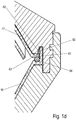
- Fig. 1 shows a section through the area of a housing 1 and a drum 2 of a separator according to the invention, with which a liquid product can be separated into two phases in a centrifugal field.
- the drum 2 has a vertical axis of rotation D. Terms used below such as “above” or “below” relate to the orientation of elements of the separator in relation to this vertical axis of rotation.
- the housing 1 has a lower base 3, a housing jacket 4 and an upper cover 5.
- the base 3 in turn has a passage 6 through which a rotatable drive spindle 7 passes.
- a drive motor 8 is preferably arranged directly below the base 3. This drive motor 8 is used to drive the drive spindle 7.
- Alternative configurations are conceivable, for example one in which the drive spindle 7 is driven with a drive belt or the like, the drive motor then being arranged elsewhere.
- a direct drive is preferred, in particular on the type of Fig. 1 , in which the drive shaft of the motor is arranged directly in a vertical extension of the drive spindle 7 is.
- the spindle construction does not have its own mounting, which makes the construction simple and relatively inexpensive to implement. This construction is simple and robust and very well suited for the lightweight drum construction.
- the function of mounting the drum is carried out in a simple manner by the electric motor or its rotor mounting
- the drum 2 On the vertically upper end of the drive spindle 7, the drum 2 is in turn placed non-rotatably relative to the drive spindle 7, so that it can be set in rotation by the drive spindle 7 and the drive motor 8.
- the drive spindle 7 could be rotatably mounted in the housing 1, here in the base 3, with one or more bearings. However, such a storage can also be dispensed with. Rather, a gap 9 is formed between the outer circumference of the drive spindle and the inner circumference of the passage 6 of the base 3. In this way, a mounting of a drive shaft 10 in the motor housing of the drive motor 8, on which the drive spindle 7 is fixed or on which it is formed in another way, can also be used in a simple manner for mounting the entire rotating system, which consists of the drum 2 and the drive spindle 7 exists, can be used.
- the drive spindle 7 is coupled directly to the output shaft of the motor and that the drive spindle 7 has no additional rotary bearing - for example no neck bearing and no foot bearing - on its outer circumference.
- a seal 72 ensures that the gap 9 is sealed.
- the seal 72 can, for example, be a mechanical seal or another suitable seal in the annular gap 9 between the parts 3, 7 rotating relative to one another.
- the drum 2 has an outer drum 11, which can also be designed as an outer drum section - and an inner drum 12.
- the outer drum section or the outer drum 11 and the inner drum 12 are preferably made of different materials.
- the outer drum 11 is preferably made of metal, in particular steel, and the inner drum 12 is preferably wholly or at least partially, in particular predominantly, made of a plastic or a plastic composite material.
- the outer drum 11 serves as a type of holder in which the inner drum 12 is inserted. This holder completely surrounds the inner drum 12 in the vertical or axial direction, at least in sections, or encloses it.
- the outer drum 11 and the inner drum 12 are preferably connected to one another in a rotationally fixed manner. This can be achieved in particular by a form fit and / or force fit between the outer drum 11 and the inner drum 12.
- the outer drum 11 has an outer drum lower part 13 which, essentially like the drum lower part of known separators, can be designed or is here without an inner drum.
- the outer drum lower part 13 is placed non-rotatably on the drive spindle 7 and preferably has a single or, here, preferably double-conical inner shape, which leads to good rotating and separating behavior on the separator drum.
- the outer drum 11 also preferably has an outer drum upper part 14.
- the lower outer drum part 13 and the upper outer drum part 14 preferably have corresponding threads 71, in the area of which they are screwed directly to one another.
- the thread of the outer drum lower part section is designed as an inner thread of the drum lower part and the thread of the outer drum upper part 14 is designed as a corresponding outer thread.
- the outer drum upper part 14 is also conical. It is also designed as a ring that is non-rotatably connected at the bottom to the lower outer drum part 13 and is designed to be open at the top so that the inner drum 12 protrudes vertically or axially upward from the outer drum, here from the upper outer drum part 14.
- the outer drum upper part 14 preferably extends only into the conical section of the inner drum upper part 17, so that the latter still protrudes vertically upwards from the outer drum upper part 14 with part of its conical area (preferably more than 20% of the vertical length of this area). It it has been shown that this already leads to very good turning behavior.
- the upper part of the outer drum can be reduced to a conical ring in this way.
- the lower outer drum part 13 and the upper outer drum part 14 are preferably made of metal, in particular steel, and preferably at least the lower drum part is designed like that of a separator drum without an inner drum 12, they can largely offer the smoothness, stability and safety of a known modern metal separator drum.
- the outer drum 11 surrounds the inner drum 12 in sections or entirely on the outside, the outer drum stabilizes the inner drum.
- the outer drum 11 advantageously contributes to optimizing the running properties of the entire drum 2 during operation at high speed.
- the wall thickness of the inner drum 12 can also be selected to be much thinner than that of a separator drum consisting solely of plastic without an outer drum 11, as in FIG WO 2014/000829 A1 suggested.
- the inner drum 12 delimits the actual separating or centrifugal chamber 15 to the outside for the centrifugal processing of a flowable product.
- the inner drum 12 is designed in such a way that it preferably rests directly against the inner circumference of the outer drum in a largely form-fitting manner.
- the inner drum 11 has an inner drum lower part 16 and an inner drum upper part 17.
- the inner drum lower part 16 and the inner drum upper part 17 are preferably each conical, so that a double-conical body is formed.
- the parts 16 and 17 consist of plastic or a plastic composite material and are connected to one another in a liquid-tight manner, in particular in the upper (inner drum lower part 16) and lower (inner drum upper part 17) flange areas 18, 19 (see FIG Figure 1b ).
- connection such as a bayonet lock between the elements to be connected, inner drum lower part 16 and inner drum upper part 17.
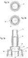
- the Figure 1c and 1d each illustrate different connection variants between the elements to be connected inner drum lower part 16 and inner drum upper part 17, in which these are connected to one another via a latching connection.
- first and second latching means 60, 63 are provided, which are intended to interact with a corresponding latching edge or contour on the other inner drum part.
- the first latching means 60 can be designed as one or more webs 61 axially formed on the outer circumference of the inner drum upper part 17, axially in the direction of the inner drum lower part, with a radially inwardly projecting latching contour 62, which the inner drum lower part 16 on the outer circumferential edge - the thus the counter-locking means forms - reaches under.
- the webs 61 can be formed with a radially inwardly projecting locking contour 62 on the inner drum lower part 16 and overlap the inner drum upper part 17 on the outer circumferential edge - which thus forms the counter-locking means 63.
- connection variants between the inner drum lower part 16 and the inner drum upper part 17 can also be advantageously implemented, for example screw connections with plastic screws and nuts or the like (not shown here). It is also an expedient connection if the inner drum lower part and the inner drum upper part are clamped together on their outer circumference with one or more clamps (not shown here). These types of connections between the inner drum parts 16, 17 are easy to handle, can be implemented inexpensively and are nevertheless very functionally reliable.
- At least one preferably circumferential sealing ring 64 can be arranged axially in order to ensure the tightness of the (plastic) inner drum ( Figure 1c and 1f ).
- This sealing ring 64 can be a separately inserted sealing ring or it can be designed as a sealing ring strip which is injection molded onto one or both of the flange areas.
- the inner drum lower part 16 and the inner drum upper part 17 each have in the region of their largest outer circumference upwards (inner drum lower part 16) and downwards (inner drum upper part 17) channels 82, 83 which are open and have a U-shaped cross-section, which mesh with one another when the inner drum 12 is in the assembled state Form a circumferentially closed annular space 84 in cross section.
- the sealing ring 64 is arranged in the annular space 84. When it rotates, it lies radially outwards and widens so that the annular space or the interior of the inner drum 12 is well sealed.
- a lock such as a latching can be formed between the inner drum lower part 16 and the inner drum upper part 17.
- the outer drum lower part 13 extends in Fig. 1f advantageously vertically so far upwards that it stabilizes the inner drum in the area of the grooves 82, 83 radially on the outside.
- the inner drum upper part 17 is screwed to the inner drum lower part with a stepped locking ring 85, with corresponding threads 86 being formed between the locking ring 85 and the inner drum lower part 17, and the locking ring 85 pressing the inner drum upper part 17 against the inner drum lower part 16.
- a very good sealing effect is also supported in this way.
- a here lower section 20 of the inner drum lower part 16 closes axially upwards as a separate part or as a one-piece with the inner drum lower part, coaxially surrounding the axis of rotation D distributor, in particular distributor attachment 21 (see again Fig. 1a ), which has a complete distributor for introducing the material to be centrifuged into the inner drum interior or centrifugal chamber 15 and to accelerate the material to be centrifuged in the circumferential direction when the drum 2 rotates.
- a blind hole-like bore is formed, into which an inlet pipe 23 opens.
- the inlet pipe 23 can also be molded directly onto the distributor attachment or formed directly in one piece with it in some other way.
- the inlet pipe 23 and the distributor attachment 21 form an inlet system which is preferably advantageously designed to be sealed off from the environment.
- the inlet pipe 23 preferably projects axially upward from the inner drum upper part 17 and rotates with the drum 2 during operation.
- the distributor attachment 21 opens into one or more distributor channels 24, which are designed at an angle to the axis of rotation and here likewise open at an angle into the actual centrifugal chamber 15.
- separating means or means for clarification such as in particular a one-part or preferably multi-part plate pack 25, are arranged that is designed as a stack of axially spaced separating plates 26, which have a conical basic shape and which are preferably placed on the distributor attachment 21 so that they cannot rotate.
- the separating means for clarification could also be designed in a different form, for example as a rib body with radial or arcuate ribs.
- the separation plates 26 have the same or different radii.
- the distributor attachment or distributor 21 can also be designed in one piece with the means for clarifying, if this is a clarifying insert made of plastic with clarifying chambers of the type DE 10 2008 052 630 A1 is trained.
- a product introduced into the inner drum interior or centrifugal chamber 15 is separated in the drum 2 into different, preferably two, product phases of different densities.
- a drainage system with two or more drainage areas is used to derive the various product phases from the drum 2.
- a conical plate is attached, in particular glued or molded, which is arranged like an upper separating plate 30 above the separating plate package, being spaced from the upper drum part so that a gap is formed between the upper drum part and the separating plate.
- a flange-like peripheral edge 31 (see Figure 1b ) placed between the flange areas 18, and 19 of the inner drum lower part 16 and the inner drum upper part 17 and there preferably firmly glued to them, which stabilizes the arrangement of the separating plate 30 and also gives the entire construction additional strength.
- a heavier liquid phase (or a still just drainable, in particular just slightly flowable solid phase) is drawn from the area of the largest inner circumference of the drum interior through one or more bores 32 in the radially outer area of the separating plate into the gap 33, which functions as a channel, between the inner drum upper part 17 and the Separating plate 30, preferably up to a second annular channel 34 - or into one or more channels, which are preferably spaced apart by ribs, - between the pipe section 29 surrounding the inlet pipe and an axial pipe extension 45 of the inner drum upper part 17.
- the cover ring body 37 is preferably of stepped design and, in its vertically uppermost area, has a connection stub 38 as a connection option for an inlet line 75 (but which is shown in FIG Fig. 2 to be recognized and explained in more detail below).
- the internally hollow connecting piece 38 opens into an axially uppermost annular space 39 on the inner circumference of the cover ring body 37, in which the upper end of the inlet pipe 23 extends axially from below, which rotates with the drum during operation of the centrifuge and which opens into the annular space 39 , but at each point of the annular space 39 to the cover ring body 37 is spaced.
- each of the annular spaces 39, 35, 36 is preferably delimited by a sealing arrangement 40, 41, 42 on one or more (here two) sealing rings, which are arranged between the outer circumference of the inlet pipe 23 and the inner wall of the annular space.
- sealing arrangements 40, 41, 42 two sealing rings axially spaced from one another, in particular in the manner of mechanical seals, are preferably provided.
- the cover ring body 37 widens further at a next step.
- the middle annular space 36 between the outer circumference of the inlet pipe 23 and the inner circumference of the cover ring body 37 is formed below the uppermost seal arrangement 40 and above the middle seal arrangement 41.
- a further connection piece 43 can be formed on the cover ring body 37, which preferably extends radially or at an angle away from the rest of the cover ring body 37.
- the pipe end, which adjoins the dividing plate 30, opens into this annular space 36 from below.
- the middle sealing arrangement 41 is arranged between the outer circumference of the pipe section 29 and the inner circumference of the cover ring body 37.
- the cover ring body 37 widens again at a next step.
- the annular space 35 between the outer circumference of the pipe section 29 and the inner circumference of the cover ring body 37 is formed below the middle seal arrangement 41 and above the lower seal arrangement 42. This lower annular space 35 serves to divert a liquid phase that is relatively lighter and heavier from the rotating system.
- connection piece 44 can be formed on the cover ring body 37, which extends (here at an angle) preferably radially away from the rest of the cover ring body 37.
- the lower sealing arrangement 42 is arranged between the outer circumference of the pipe extension 45 of the inner drum upper part 17 and the inner circumference of the cover ring body 37.
- Leakage chambers 80 can be formed on the sealing arrangements 40, 41, 42, from which leakage fluid can flow out of the rotating system through connection pieces 81, lines and / or leakage containers being connected to the connection pieces 81 in turn).
- the ring body 37 widens further below the sealing arrangement 42. It is fixed by means of fastening means on its lower peripheral edge to an upper opening of the housing, which the ring body and the pipe socket 45 and the elements penetrating this inside the pipe socket penetrate. This fixing can be done, for example, by means of circumferentially distributed screws 22 which are screwed tightly to the housing 1 (preferably to the cover 5).
- the ring body 37 can have corresponding threaded screw receptacles 73 for this purpose.
- the inner drum 12 is connected to the outer drum 11 in a form-fitting and / or force-fitting manner.
- a non-positive connection can be implemented in a simple manner in that the flange areas 18 and 19 as well as the outer edge 31 of the separating plate 30 extend into the screwing area between the lower outer drum part and the upper outer drum part, where they each rest against the steps of these parts and when the upper drum part is screwed together be clamped screwed between these in the lower part of the drum ( Figure 1b ).
- positive locking means such as ribs 87 (and / or grooves) on the outer circumference of the inner drum and corresponding grooves 88 (and (or ribs) on the inner circumference of the outer drum 11 can be provided, which interlock and thus connect the two elements of the inner drum 12 and the outer drum 11 in a rotationally fixed manner ( Fig. 1a ).
- one or more of the ribs 87 are distributed on the outside (on the outer surface or the outer casing of the outer drum), preferably circumferentially distributed on the inner drum lower part 16 and correspondingly one or more of the grooves 88 are circumferentially distributed on the outside (on the inner surface facing the inner drum) are formed on the outer drum lower part 13.
- the outer drum lower part 13 is here advantageously double-conical and has an inner conical area 13a and an oppositely oriented outer conical area 13b.
- the inner drum lower part 16 has a corresponding double-conical shape with an inner conical area 16a and an outer conical area 16b.
- the form-fit means (s), in particular ribs 87, is / are preferably formed on the outside of the inner conical region 16a of the inner drum lower part 16 or protrude from it and the corresponding form-fit means (s), in particular grooves / recesses 88, is / are correspondingly on the inner conical area Area 13a of the inner drum upper part 13 is formed on its inner surface. It is precisely the arrangement in this area close to the drive spindle 7 that enables a very good torque transmission from the outer drum to the inner drum that guarantees very smooth running. A torque transmission in other areas on the outside of the inner and outer drums is also conceivable.
- the inner drum 12 will also lie, widening radially, on the inner circumference of the outer drum 11, which improves the torque transmission and the rotating entrainment of the inner drum 12 by the driven outer drum 11.
- the inner drum 12 can be disposed of after a sufficiently large batch of product has been processed.
- the preferably metallic outer drum 11, on the other hand, is used again. Since it cannot come into contact with the product during operation, cleaning it is very easy or less important. Due to the outer drum 11, the inner drum 12 can be made quite thin-walled. With complete disposal, there is accordingly very little plastic waste.
- Fig. 1 shows an embodiment as a two-phase separating machine (separation of a product into the phases: "liquid / liquid”), three-phase machines (for separation into three phases) can also be implemented (not shown here).
- the product is preferably, but not necessarily, a fermentation broth to be concentrated
- the entire inner drum, together with the inlet and outlet system is designed as an exchangeable, preassembled module made of plastic or a plastic composite material.
- the outer drum section 11 essentially serves as a holder for the inner drum 12, which in particular improves the running properties of the inner drum 12.
- the design of the upper part of the outer drum as a ring is optimized in the experiment. It can thereby be determined up to which conical area the ring-like outer drum cover or the outer drum upper part must surround the inner drum upper part upwards.
- the structure of the housing 1 will be considered in more detail below.
- the housing 1 has the base 3, a preferably cylindrical housing jacket 4 and the cover 5. Only in the area of the cover ring body 37 does the housing come into contact with the plastic area that can be disposed of after operation.
- the base 3 is designed here as a separate base plate 46.
- the base plate 46 is round.
- the housing jacket 4 is arranged on the floor.
- an edge area of the base serves as a flange-like support surface 47 for a lower flange section 48 of the housing jacket 4, which is cylindrical in this preferred embodiment.
- the housing jacket 4 also has an upper flange section 49 on which the cover 5 is screwed.
- the base plate 36 can be used to rest on an abutment, not shown here, such as a foundation or a machine frame.
- an abutment not shown here, such as a foundation or a machine frame.
- bores 74 are also formed in the flange section 48, to which the flange section can be fixed to the abutment (for example with screws not shown here).
- the housing 1 has a drain opening 59, preferably in its bottom 3, through which any liquid - which occurs in the housing, for example due to an unforeseen leakage or which would collect there for other reasons - can flow off.
- a discharge line such as a drain hose for discharging this liquid into a container can be arranged at a connection of the opening 59.
- the drive motor is preferably an electric motor which is directly is arranged in the axial extension of the drive spindle 7, preferably on the side facing away from the drum.
- the drive spindle 7 is preferably axially connected directly to the output shaft 10 by means of a bolt. It is also connected to the output shaft of the electric motor in a rotationally fixed manner in the circumferential direction by means of a torque transmission means, preferably a feather key (not shown here).
- the torque transmission means can also be designed in a different form, for example as a torque transmission contour (not shown here in each case).
- a terminal box 75 is arranged on the motor 8.
- the rotatable drum 2 can be connected to the drive spindle construction with a press fit (e.g. in a conical section) or by means of some other torque transmission means (not shown here).
- the motor 8 is also fastened here on its side facing the spindle 7 with a flange section 50 on the bottom of the housing 1, for example screwed on with screw bolts.
- a terminal box 51 is also arranged on the motor 8.
- the invention also provides a device for at least axially securing the cover ring body 37 to an element of the rotating system of the separator of the inner drum, in any case in the transport state, i.e. in the state not mounted in the outer drum and in the housing 1.
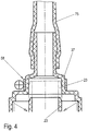
- FIG. 2 an upper section of the cover ring body 37 with the connecting piece 38 as a connection option for a hose-like inlet line 75 and an upper section of the inlet pipe and the upper sealing arrangement 40 are shown.
- the hoses can be glued shut at the ends facing away from the connecting pieces. Before commissioning, the glued ends are cut off and welded to a piece of tubing that comes from the fermenter, for example.
- Other variants for connecting the hoses and nozzles and for closing any open line ends are also conceivable.
- coupling elements are conceivable for connecting, which are designed to be latching, for example, or closing the ends with cable ties or similar elements is conceivable.
- the Figs. 2 to 4 also show the inlet pipe 23 in an axially further (here upwards in the direction of the upper connection stub 38) pushed into the body 37 (dashed line) and in a slightly further axially downwardly moved state (solid line).
- the dashed state or the further pushed-in state of the inlet pipe 23 indicates the transport state and the non-dashed state indicates the installation state in the outer drum 11 for operation.
- the axial transport lock is based on a force fit and / or form fit.
- a combined force and form fit is realized.
- a projection 53 arranged on a leaf spring 52 for example a pin, engages in an annular groove 54 on the outer circumference of the inlet pipe 23 when it is pushed further into the cover ring body 37.
- the force of the spring is chosen in such a way that a good transport security is realized, but that it is still possible after To release the transport lock during transport during installation by means of a targeted axial movement of the inlet pipe downwards.
- FIG. 3 Such a form fit is achieved in an annular groove 54 of the inlet pipe 23 in that a radially inwardly projecting web 55 on the cover ring body 37 engages on the inside in the annular groove 54 of the inlet pipe 23.
- a taper / bevel 56 at the free upper end of the inlet pipe 23 it can be pushed into the transport securing position shown in dashed lines, in particular before the disposal of the rotating system or before the initial transport.
- a releasable frictional connection is achieved by placing a type of tension ring 58 (similar to a tensionable hose clamp) around the outside of the cover ring body 37 and clamped it so that it presses the cover ring body 37 with a force fit onto the outer circumference of the feed pipe 23 that is pushed in further.
- a type of tension ring 58 similar to a tensionable hose clamp
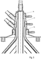
- the Fig. 5 and 6th illustrate that reinforcement elements made of plastic, in particular the inner drum, can be provided locally.
- these reinforcing elements are designed as sleeves 76, 77, 78.
- These sleeves lie protectively radially between each one of the sealing arrangements 40, 41, 42 and the associated inner pipe / pipe section / pipe socket 23, 29, 45 and reinforce them.
- one or more of the sleeves can themselves also form a section of a pipe / pipe section / pipe extension 23, 29, 45.
- a sleeve 23a forms an axial end of the inlet pipe 23.
- the sealing arrangement 40 is arranged radially on the outside of the sleeve 23a.
- the sleeves 23a, 76, 77, 78 can be designed to be insulating or heat-conducting, depending on the requirements. They are preferably also made of plastic (preferably a high temperature resistant and preferably high strength Plastic). However, it is also conceivable and preferred to manufacture them in a different way, for example from other materials, including plastic composite materials or other composite materials. Reinforcement elements made in particular of glass, metal, plastic-to-metal compounds (e.g. plastic with metal fabric to dissipate heat) are conceivable. These are possibly separated during recycling or disposal.
- the sleeves 23a, 76, 77, 78 heat up less than the rest of the pipe / pipe section / pipe socket 23, 29, 45 due to the choice of material made of metal. In this case, it is particularly advantageous if the sleeve virtually alone forms a pipe section of the pipe / pipe section / pipe extension 23, 29, 45.
- the sleeve - for example 23a - itself forms a section, in particular one end of a pipe, it is expedient to connect this firmly to the rest of the pipe / pipe section / pipe socket 23, 29, 45, preferably inseparably. In the latter case, it is advisable to glue the sleeve to the remaining pipe / pipe section / pipe socket 23, 29, 45 or to place it in the appropriate mold when the plastic pipe is injection-molded, so that an intimate connection, in particular between Metal and plastic is created.
- the sleeve 23a, 76, 77, 78 and the pipe / pipe section / pipe socket 23, 29, 45 can also overlap or engage in one another in sections ( Fig. 7 ).
- the sleeve made of metal, the sleeve has a relatively high heat absorption capacity, so that it does not heat up too much, in particular when the drum is started up to operating speed. This in turn protects temperature-sensitive elements, in particular the mechanical seals arranged in their area, which are preferably adjacent to them.
- Fig. 6 have one or more of the sleeves 76, 77, 78 - here on the inner peripheral edge - one or more grooves, in particular annular grooves 79, or one or more chambers, which is reduced by the formation of air chambers it contributes to heat conduction and therefore protects the adjacent elements, especially seals.
Landscapes
- Centrifugal Separators (AREA)
Claims (27)
- Séparateur pour la centrifugation d'un produit fluide, ayant au moins les caractéristiques suivantes :a. un tambour (2) capable de rotation, qui délimite un espace de centrifugation (15),
et caractérisé en ce queb. le tambour (2) présente un dispositif de support externe et un tambour interne (12) introduit et disposé dans le dispositif de support externe, etc. un moyen pour la clarification du produit à traiter dans le champ centrifuge est disposé dans le tambour interne (12), le moyen de clarification étant un paquet de disques (25) formé d'une pile de disques séparateurs (26),d. dans lequel le dispositif de support externe est conformé comme un anneau extérieur fermé sur sa circonférence, qui entoure le tambour interne (12) en partie dans le sens axial, et/ou le dispositif de support externe est conformé comme un tambour externe (11) dans lequel le tambour interne (12) est disposé,e. dans lequel le tambour externe (11) sert de monture dans laquelle le tambour interne (12) est inséré, et le tambour externe (11) entoure seulement en partie le tambour interne (12) dans le sens axial, de sorte que le tambour interne (12) dépasse dans le sens axial du tambour externe (11), ou le tambour externe (11) entoure complètement le tambour interne (12) dans le sens axial,f. dans lequel le tambour interne (12), ainsi qu'un système d'arrivée et d'écoulement, est conçu comme un module interchangeable préassem blé,g. qui est principalement fait de matière plastique ou d'une matière plastique composite eth. dans lequel le système d'arrivée et le système d'écoulement sont formés par une construction étanche sur le tambour interne (12). - Séparateur selon l'une des revendications précédentes, caractérisé en ce que le tambour interne et le tambour externe (12, 11) se composent de matériaux différents, le tambour interne (12) se composant de matière plastique ou d'une matière plastique composite et le tambour externe (11) se composant de métal, en particulier d'acier.
- Séparateur selon l'une des revendications précédentes, caractérisé en ce que le tambour externe (11) présente une partie inférieure de tambour externe (13) et une partie supérieure de tambour externe (14), la partie inférieure de tambour externe (13) et la partie supérieure de tambour externe (14) étant fixées l'une à l'autre par des moyens de vissage, lesquels moyens de vissage comprennenta. des boulons filetés oub. un jonc de verrouillage ouc. un filetage entre la partie supérieure de tambour externe (14) et la partie inférieure de tambour externe (13).
- Séparateur selon l'une des revendications précédentes, caractérisé en ce que le tambour interne (12) présente une partie inférieure de tambour interne (16) et une partie supérieure de tambour interne (17), la partie inférieure de tambour interne (16) et la partie supérieure de tambour interne (17) étant assemblées l'une à l'autre de façon non démontable, la partie inférieure de tambour interne (16) et la partie supérieure de tambour interne (17) étant de préférence assemblées l'une à l'autre par solidarité de matière, en particulier collées ou soudées, et/ou la partie inférieure de tambour interne (16) et la partie supérieure de tambour interne (17) étant assemblées mécaniquement l'une à l'autre et/ou au moins une garniture d'étanchéité, en particulier un joint d'étanchéité circonférentiel (64), étant disposée ou formée entre la partie inférieure de tambour interne (16) et la partie supérieure de tambour interne (17).
- Séparateur selon l'une des revendications précédentes, caractérisé en ce que la partie supérieure de tambour externe (14) est conformée comme un anneau et ouverte vers le haut dans le sens axial, de sorte que la partie supérieure de tambour interne dépasse d'elle dans le sens axial.
- Séparateur selon l'une des revendications précédentes, caractérisé en ce qu'une des pièces suivantes ou les deux ont une forme conique : la partie supérieure de tambour externe ou interne (14, 17) et la partie inférieure de tambour externe ou interne (13, 16), la partie inférieure de tambour externe (13) ayant de préférence la forme d'un double cône et comportant une partie conique intérieure (13a) et une partie conique extérieure (13b), et en ce que la partie inférieure de tambour interne (16) présente une forme de double cône correspondante avec une partie conique intérieure (16a) et une partie conique extérieure (16b).
- Séparateur selon l'une des revendications précédentes, caractérisé en ce que le tambour interne (12) et le tambour externe (11) sont assemblés l'un à l'autre de façon solidaire en rotation par friction et/ou par engagement positif.
- Séparateur selon l'une des revendications précédentes, caractérisé en ce que le tambour interne (12) et le tambour externe (11) sont assemblés l'un à l'autre de façon solidaire en rotation par au moins un ou plusieurs moyens d'engagement positif en correspondance, le tambour interne (12) présentant comme moyens d'engagement positif au moins une ou plusieurs nervures (87) qui se mettent en prise dans une ou plusieurs rainures (88) correspondantes sur la partie inférieure de tambour externe (13), les une ou plusieurs nervures (87) étant formées sur la surface extérieure de la partie conique intérieure (16a) de la partie inférieure de tambour interne (16), et/ou en ce que les une ou plusieurs rainures (88) sont formées en correspondance sur la surface intérieure de la partie conique intérieure (13a) de la partie supérieure de tambour interne (13).
- Séparateur selon l'une des revendications précédentes, caractérisé en ce que le tambour externe (11) est entraîné par un moteur d'entraînement (8).
- Séparateur selon l'une des revendications précédentes, caractérisé en ce que la pile de disques séparateurs (26) est faite de matière plastique ou d'une matière plastique composite.
- Séparateur selon l'une des revendications précédentes, caractérisé en ce que la partie supérieure de tambour externe (14) s'étend jusqu'à la partie conique de la partie supérieure de tambour interne (17), de telle sorte que cette dernière dépasse encore verticalement vers le haut avec une partie de sa région conique hors de la partie supérieure de tambour externe (14).
- Séparateur selon l'une des revendications précédentes, caractérisé en ce que la partie inférieure de tambour externe (13) est reliée de manière solidaire en rotation avec une tige d'entraînement (7).
- Séparateur selon l'une des revendications précédentes, caractérisé en ce qu'un système d'arrivée et un système d'écoulement du tambour sont formés exclusivement sur le tambour interne (12) et/ou en ce qu'aucune ouverture d'extraction de solides menant hors du tambour interne (12) dans le sens radial vers l'espace environnant le tambour interne n'est formée dans la paroi du tambour interne.
- Séparateur selon l'une des revendications précédentes, caractérisé en ce que le système d'arrivée et le système d'écoulement sont formés par une construction étanche sur le tambour interne (12).
- Séparateur selon l'une des revendications précédentes, caractérisé en ce que le tambour interne comporte le système d'arrivée pour amener le produit fluide et le système d'écoulement pour extraire différentes phases de produit du tambour (2), le système d'écoulement comportant de préférence deux zones d'écoulement ou plus.
- Séparateur selon l'une des revendications précédentes, caractérisé en ce que le système d'écoulement est réalisé sans pompe centripète.
- Séparateur selon l'une des revendications précédentes, caractérisé en ce que le système d'arrivée et le système d'écoulement présentent un corps annulaire de couverture (37) qui ne tourne pas avec le tambour en fonctionnement, le système d'arrivée présentant un tuyau d'arrivée (23) qui est réalisé comme un élément en rotation (2) avec le tambour, lequel tuyau d'arrivée (23) dépasse à l'intérieur du corps annulaire de couverture (37).
- Séparateur selon l'une des revendications précédentes, caractérisé en ce qu'un ou plusieurs autres éléments de tuyau dépassent à l'intérieur du corps annulaire (37) et tournent avec le tambour (2) en fonctionnement, une ou plusieurs dispositions d'étanchéité (40, 41, 42) comportant chacune un ou plusieurs joints d'étanchéité étant disposées entre le corps annulaire de couverture (37) et les éléments de tuyau ou extrémités de tuyau (23, 29, 45) en rotation du tambour.
- Séparateur selon l'une des revendications précédentes, caractérisé en ce qu'au moins un ou plusieurs des éléments de tuyau du tambour tournant avec le tambour pendant le fonctionnement, en particulier le tuyau d'arrivée (23), sont guidés en translation dans le sens axial dans le corps annulaire de couverture (37) et en ce qu'il est prévu un dispositif pour la fixation amovible de l'au moins un élément de tuyau dans une position axiale dans le corps annulaire de couverture (37), le dispositif de fixation amovible de l'élément de tuyau dans une position axiale dans le corps annulaire de couverture (37) réalisant de préférence un engagement positif et/ou par friction qui peut être défait.
- Séparateur selon l'une des revendications précédentes, caractérisé en ce que la partie inférieure du tambour et muni d'un raccord de distribution (21) qui présente des canaux de distribution pour le transfert du produit à traiter d'un tuyau d'arrivée à l'espace de centrifugation ou à l'espace intérieur du tambour (15).
- Séparateur selon l'une des revendications précédentes, caractérisé en ce que toutes les zones du tambour (2) venant en contact avec le produit se composent de matière plastique ou d'une matière plastique composite et/ou en ce que le tambour (2) est disposée dans un caisson (1).
- Séparateur selon l'une des revendications précédentes, caractérisé en ce que la tige d'entraînement (7) est entraînée avec une courroie d'entraînement, le moteur d'entraînement (8) étant alors disposé ailleurs que directement en dessous d'un fond (3) du caisson (1).
- Séparateur selon l'une des revendications précédentes, caractérisé en ce qu'au moins un canal d'écoulement est intégré dans la partie supérieure de tambour interne (17) pour une phase lourde du produit et/ou en ce que les zones d'écoulement du système d'écoulement sont réalisées comme des canaux annulaires qui débouchent dans le sens axial dans des espaces annulaires du corps annulaire de couverture (37).
- Séparateur selon l'une des revendications précédentes, caractérisé en ce que sont prévus un ou plusieurs éléments de renfort, en particulier pour un tuyau, un tronçon de tuyau ou un raccord de tuyau en plastique ou en matière plastique composite, le ou les éléments de renfort étant de préférence conformés comme des douilles (76, 77, 78) faites de préférence de céramique ou de métal.
- Séparateur selon l'une des revendications précédentes, caractérisé en ce que toutes les parties du tambour interne qui tournent en fonctionnement et les parties de son système d'arrivée et d'écoulement qui ne tournent pas en fonctionnement, si elles viennent en contact avec le produit, se composent de matière plastique ou d'une matière plastique composite.
- Séparateur selon l'une des revendications précédentes, caractérisé en ce que toutes les parties du tambour interne qui tournent en fonctionnement et les parties de son système d'arrivée et d'écoulement qui ne tournent pas en fonctionnement, si elles viennent en contact avec le produit, sauf les garnitures d'étanchéité à prévoir le cas échéant, se composent de matière plastique ou d'une matière plastique composite.
- Séparateur selon la revendication 18, caractérisé en ce que les garnitures d'étanchéité sont conçues comme des garnitures mécaniques.
Priority Applications (3)
| Application Number | Priority Date | Filing Date | Title |
|---|---|---|---|
| EP21164482.8A EP3862096B1 (fr) | 2014-05-28 | 2015-05-26 | Séparateur |
| PL15725318.8T PL3148701T5 (pl) | 2014-05-28 | 2015-05-26 | Separator |
| SI201531784T SI3148701T2 (sl) | 2014-05-28 | 2015-05-26 | Ločevalnik |
Applications Claiming Priority (2)
| Application Number | Priority Date | Filing Date | Title |
|---|---|---|---|
| DE102014107604 | 2014-05-28 | ||
| PCT/EP2015/061599 WO2015181175A2 (fr) | 2014-05-28 | 2015-05-26 | Séparateur |
Related Child Applications (2)
| Application Number | Title | Priority Date | Filing Date |
|---|---|---|---|
| EP21164482.8A Division EP3862096B1 (fr) | 2014-05-28 | 2015-05-26 | Séparateur |
| EP21164482.8A Division-Into EP3862096B1 (fr) | 2014-05-28 | 2015-05-26 | Séparateur |
Publications (3)
| Publication Number | Publication Date |
|---|---|
| EP3148701A2 EP3148701A2 (fr) | 2017-04-05 |
| EP3148701B1 true EP3148701B1 (fr) | 2021-11-24 |
| EP3148701B2 EP3148701B2 (fr) | 2025-08-27 |
Family
ID=53269478
Family Applications (2)
| Application Number | Title | Priority Date | Filing Date |
|---|---|---|---|
| EP21164482.8A Active EP3862096B1 (fr) | 2014-05-28 | 2015-05-26 | Séparateur |
| EP15725318.8A Active EP3148701B2 (fr) | 2014-05-28 | 2015-05-26 | Séparateur |
Family Applications Before (1)
| Application Number | Title | Priority Date | Filing Date |
|---|---|---|---|
| EP21164482.8A Active EP3862096B1 (fr) | 2014-05-28 | 2015-05-26 | Séparateur |
Country Status (11)
| Country | Link |
|---|---|
| US (1) | US20170189915A1 (fr) |
| EP (2) | EP3862096B1 (fr) |
| CN (1) | CN106413905A (fr) |
| DE (1) | DE102015108272A1 (fr) |
| DK (1) | DK3148701T4 (fr) |
| ES (1) | ES2907031T5 (fr) |
| FI (1) | FI3148701T4 (fr) |
| HU (1) | HUE057395T2 (fr) |
| PL (1) | PL3148701T5 (fr) |
| SI (1) | SI3148701T2 (fr) |
| WO (1) | WO2015181175A2 (fr) |
Families Citing this family (14)
| Publication number | Priority date | Publication date | Assignee | Title |
|---|---|---|---|---|
| DE102015101344A1 (de) * | 2015-01-29 | 2016-08-04 | Gea Mechanical Equipment Gmbh | Separator |
| DE102015117375A1 (de) * | 2015-10-13 | 2017-04-13 | Gea Mechanical Equipment Gmbh | Separator |
| US20180008990A1 (en) * | 2016-07-07 | 2018-01-11 | Tobi D. Mengle | Centrifugal mechanical separator produced by additive manufacturing |
| EP3666394B1 (fr) | 2018-12-10 | 2026-02-25 | Alfa Laval Corporate AB | Séparateur centrifuge modulaire et son unité de base et système |
| EP3666389B1 (fr) | 2018-12-10 | 2021-08-04 | Alfa Laval Corporate AB | Séparateur centrifuge |
| EP3666386B1 (fr) | 2018-12-10 | 2023-06-14 | Alfa Laval Corporate AB | Séparateur centrifuge |
| EP3666385B1 (fr) | 2018-12-10 | 2021-07-14 | Alfa Laval Corporate AB | Insert de séparation échangeable et séparateur centrifuge modulaire et procédé |
| EP3666388A1 (fr) | 2018-12-10 | 2020-06-17 | Alfa Laval Corporate AB | Système et procédé de séparation centrifuge |
| EP3666384B1 (fr) | 2018-12-10 | 2021-08-18 | Alfa Laval Corporate AB | Séparateur centrifuge et procédé d'élimination de verrous d'air dans un séparateur centrifuge |
| CN109847949B (zh) * | 2019-04-18 | 2021-05-11 | 沈阳工业大学 | 一种可变换多流道的多功能碟式分离机的可变换流道结构 |
| JP7779904B2 (ja) * | 2020-08-14 | 2025-12-03 | ファイバーライト・セントリフュージ・エルエルシー | 連続バイオプロセス遠心分離機ロータ |
| EP4088820B1 (fr) | 2021-05-12 | 2026-03-04 | Alfa Laval Corporate AB | Système modulaire de séparateur centrifuge |
| DE202022104151U1 (de) | 2022-07-22 | 2023-10-30 | Gea Westfalia Separator Group Gmbh | Transportsicherung für einen Separatoreinsatz eines Separators |
| DE102025127994A1 (de) * | 2024-07-23 | 2026-01-29 | Gea Westfalia Separator Group Gmbh | Separatoreinsatz sowie Separator mit einem solchen Separatoreinsatz |
Citations (15)
| Publication number | Priority date | Publication date | Assignee | Title |
|---|---|---|---|---|
| US656423A (en) * | 1897-12-29 | 1900-08-21 | Radiator Ab | Centrifugal cream-separator. |
| FR971978A (fr) * | 1940-11-28 | 1951-01-24 | Bernard Moteurs | Perfectionnements apportés aux appareils centrifuges, notamment aux écrémeuses |
| US3012710A (en) | 1957-10-30 | 1961-12-12 | Westfalia Separator Ag | Centrifugal separator having lining of elastomer material |
| US4950220A (en) | 1987-07-13 | 1990-08-21 | Westfalia Separator Ag | Throughput centrifuge for industrial production of proteins from human blood plasma |
| EP0346056B1 (fr) | 1988-06-07 | 1993-12-29 | Westfalia Separator AG | Séparateur antrifuge |
| US5387174A (en) | 1993-01-29 | 1995-02-07 | Elp Rochat | Centrifugal separator with disposable bowl assembly |
| US5637217A (en) | 1995-01-25 | 1997-06-10 | Fleetguard, Inc. | Self-driven, cone-stack type centrifuge |
| US20020020679A1 (en) | 2000-04-11 | 2002-02-21 | Glen Jorgensen | Sealed centrifugal clarifier |
| WO2008013495A1 (fr) | 2006-06-20 | 2008-01-31 | Alfa Laval Corporate Ab | Séparateur centrifuge |
| US20080132396A1 (en) | 2005-03-11 | 2008-06-05 | Amirkhanian Hendrik N | Spiral vane insert for a centrifuge |
| US20110319248A1 (en) | 2011-09-02 | 2011-12-29 | Nathan Starbard | Single Use Centrifuge |
| US20120275970A1 (en) | 2010-11-19 | 2012-11-01 | Nash John E | Centrifuge |
| US20130089917A1 (en) | 2008-04-22 | 2013-04-11 | Pneumatic Scale Corporation | Single Use Centrifuge System for Highly Concentrated and/or Turbid Feeds |
| US8475352B2 (en) | 2008-12-29 | 2013-07-02 | Wagner Development, Inc. | Solids discharge centrifugal separator with disposable contact elements |
| WO2014000829A1 (fr) | 2012-06-25 | 2014-01-03 | Gea Mechanical Equipment Gmbh | Séparateur |
Family Cites Families (15)
| Publication number | Priority date | Publication date | Assignee | Title |
|---|---|---|---|---|
| US960768A (en) * | 1909-06-16 | 1910-06-07 | Gustaf M Anderson | Centrifugal cream-separator. |
| US2017734A (en) | 1933-01-24 | 1935-10-15 | Int Harvester Co | Cream separator bowl |
| NL66060C (fr) | 1940-02-13 | |||
| DE1103854B (de) * | 1958-12-24 | 1961-03-30 | Cham Ag Maschf | Kontinuierlich arbeitende Vollmantelzentrifuge |
| DE1243593B (de) * | 1965-03-27 | 1967-06-29 | Hein Lehmann Ag | Zentrifuge zum kontinuierlichen Trennen von Feststoff-Fluessigkeits-Gemischen, insbesondere Zuckerzentrifuge |
| DK625073A (fr) * | 1973-11-20 | 1975-08-04 | Smidth & Co As F L | |
| US4140268A (en) * | 1977-03-15 | 1979-02-20 | Haemo-Transfer S.A. | Centrifugating device for biological liquids, having a rotatable container, and supporting bracket therefor |
| SE448429B (sv) * | 1985-07-05 | 1987-02-23 | Alfa Laval Separation Ab | Centrifugalseparator forsedd med styrorgan for separeringsplatarna |
| JPS62117649A (ja) | 1985-11-15 | 1987-05-29 | Mitsubishi Heavy Ind Ltd | 遠心分離機 |
| DE19835120C1 (de) * | 1998-08-04 | 1999-10-21 | Westfalia Separator Ag | Verfahren und Vorrichtung zum Einstellen des Flüssigkeitsgehalts des aus einer selbstentleerenden Schleudertrommel eines Separators ausgetragenen Feststoffes |
| CN2756319Y (zh) * | 2004-08-19 | 2006-02-08 | 上海航发机械有限公司 | 悬吊转鼓碟式分离机 |
| CN201150880Y (zh) * | 2008-05-21 | 2008-11-19 | 温岭市华益分离设备厂 | 一种高效碟式分离机 |
| DE102008052630A1 (de) | 2008-10-22 | 2010-04-29 | Gea Westfalia Separator Gmbh | Zentrifuge |
| AU2013337284B2 (en) * | 2012-11-05 | 2018-03-08 | Haemonetics Corporation | Continuous flow separation chamber |
| CN103464308B (zh) * | 2013-09-18 | 2016-03-23 | 浙江索纳克生物科技有限公司 | 一种高性能碟式分离机转鼓 |
-
2015
- 2015-05-26 SI SI201531784T patent/SI3148701T2/sl unknown
- 2015-05-26 WO PCT/EP2015/061599 patent/WO2015181175A2/fr not_active Ceased
- 2015-05-26 EP EP21164482.8A patent/EP3862096B1/fr active Active
- 2015-05-26 FI FIEP15725318.8T patent/FI3148701T4/fi active
- 2015-05-26 US US15/313,279 patent/US20170189915A1/en not_active Abandoned
- 2015-05-26 DE DE102015108272.1A patent/DE102015108272A1/de not_active Withdrawn
- 2015-05-26 EP EP15725318.8A patent/EP3148701B2/fr active Active
- 2015-05-26 ES ES15725318T patent/ES2907031T5/es active Active
- 2015-05-26 PL PL15725318.8T patent/PL3148701T5/pl unknown
- 2015-05-26 CN CN201580028045.2A patent/CN106413905A/zh active Pending
- 2015-05-26 DK DK15725318.8T patent/DK3148701T4/da active
- 2015-05-26 HU HUE15725318A patent/HUE057395T2/hu unknown
Patent Citations (15)
| Publication number | Priority date | Publication date | Assignee | Title |
|---|---|---|---|---|
| US656423A (en) * | 1897-12-29 | 1900-08-21 | Radiator Ab | Centrifugal cream-separator. |
| FR971978A (fr) * | 1940-11-28 | 1951-01-24 | Bernard Moteurs | Perfectionnements apportés aux appareils centrifuges, notamment aux écrémeuses |
| US3012710A (en) | 1957-10-30 | 1961-12-12 | Westfalia Separator Ag | Centrifugal separator having lining of elastomer material |
| US4950220A (en) | 1987-07-13 | 1990-08-21 | Westfalia Separator Ag | Throughput centrifuge for industrial production of proteins from human blood plasma |
| EP0346056B1 (fr) | 1988-06-07 | 1993-12-29 | Westfalia Separator AG | Séparateur antrifuge |
| US5387174A (en) | 1993-01-29 | 1995-02-07 | Elp Rochat | Centrifugal separator with disposable bowl assembly |
| US5637217A (en) | 1995-01-25 | 1997-06-10 | Fleetguard, Inc. | Self-driven, cone-stack type centrifuge |
| US20020020679A1 (en) | 2000-04-11 | 2002-02-21 | Glen Jorgensen | Sealed centrifugal clarifier |
| US20080132396A1 (en) | 2005-03-11 | 2008-06-05 | Amirkhanian Hendrik N | Spiral vane insert for a centrifuge |
| WO2008013495A1 (fr) | 2006-06-20 | 2008-01-31 | Alfa Laval Corporate Ab | Séparateur centrifuge |
| US20130089917A1 (en) | 2008-04-22 | 2013-04-11 | Pneumatic Scale Corporation | Single Use Centrifuge System for Highly Concentrated and/or Turbid Feeds |
| US8475352B2 (en) | 2008-12-29 | 2013-07-02 | Wagner Development, Inc. | Solids discharge centrifugal separator with disposable contact elements |
| US20120275970A1 (en) | 2010-11-19 | 2012-11-01 | Nash John E | Centrifuge |
| US20110319248A1 (en) | 2011-09-02 | 2011-12-29 | Nathan Starbard | Single Use Centrifuge |
| WO2014000829A1 (fr) | 2012-06-25 | 2014-01-03 | Gea Mechanical Equipment Gmbh | Séparateur |
Non-Patent Citations (2)
| Title |
|---|
| ANONYMOUS: "Gleitringdichtung", WIKIPEDIA, 4 June 2024 (2024-06-04), XP093196483, Retrieved from the Internet <URL:https://de.wikipedia.org/w/index.php?title=Gleitringdichtung&oldid=245621135> |
| WERNER H. STAHL: "Fest-Flüssig-Trennung - Industrie-Zentrifugen, Band II, Maschinen- & Verfahrenstechnik", 1 January 2004, DRM PRESS, ISBN: 3-9522794-0-4, article STAHL, WERNER HELMUT : "6.4 Konstruktiver Aufbau von Separatoren ", pages: 749 - 750, XP009559095 |
Also Published As
| Publication number | Publication date |
|---|---|
| FI3148701T4 (fi) | 2025-11-11 |
| EP3148701A2 (fr) | 2017-04-05 |
| US20170189915A1 (en) | 2017-07-06 |
| DK3148701T3 (da) | 2022-02-07 |
| EP3862096B1 (fr) | 2025-09-10 |
| WO2015181175A3 (fr) | 2016-03-17 |
| SI3148701T1 (sl) | 2022-04-29 |
| HUE057395T2 (hu) | 2022-05-28 |
| CN106413905A (zh) | 2017-02-15 |
| EP3148701B2 (fr) | 2025-08-27 |
| DE102015108272A1 (de) | 2015-12-03 |
| PL3148701T5 (pl) | 2025-12-22 |
| WO2015181175A2 (fr) | 2015-12-03 |
| EP3862096A1 (fr) | 2021-08-11 |
| ES2907031T3 (es) | 2022-04-21 |
| ES2907031T5 (en) | 2026-01-29 |
| SI3148701T2 (sl) | 2025-12-31 |
| PL3148701T3 (pl) | 2022-03-28 |
| DK3148701T4 (da) | 2025-12-01 |
Similar Documents
| Publication | Publication Date | Title |
|---|---|---|
| EP3148701B1 (fr) | Séparateur | |
| WO2015181177A1 (fr) | Séparateur | |
| EP3229970B1 (fr) | Séparateur | |
| EP2864053B1 (fr) | Séparateur | |
| WO2016192927A1 (fr) | Séparateur | |
| DE69613351T2 (de) | Einlaufvorrichtung eines zentrifugalabscheiders | |
| EP1056904A2 (fr) | Centrifugeuse a enveloppe pleine pour melanges, en particulier pour suspensions de matieres fibreuses utilisees dans l'industrie du papier | |
| WO2017063764A1 (fr) | Séparateur | |
| EP3930910A1 (fr) | Séparateur | |
| EP4037839B1 (fr) | Centrifugeuse à vis pour cuve à matières solides | |
| WO2016142161A1 (fr) | Séparateur | |
| DE102022100511A1 (de) | Vollmantel-Schneckenzentrifuge und Verfahren zur Regelung des Trennprozesses der Vollmantel-Schneckenzentrifuge | |
| EP1998896B1 (fr) | Centrifugeuse a vis et enveloppe pleine dotee d'ouvertures d'evacuation pour le vidage partiel et le vidage residuel du tambour | |
| EP3250326A1 (fr) | Séparateur | |
| DE102016115557A1 (de) | Zentrifuge mit einer Schälscheibe | |
| DE102023116567A1 (de) | Vollmantel-Schneckenzentrifuge | |
| DE202015101346U1 (de) | Separator mit Trommelwerkzeug | |
| EP4171438B1 (fr) | Séparateur comprenant un élément d'étanchéité intégré pour la séparation fluide-air | |
| DE102025127994A1 (de) | Separatoreinsatz sowie Separator mit einem solchen Separatoreinsatz | |
| DE3237215A1 (de) | Zentrifugalseparator | |
| DE8420440U1 (de) | Ueberlauf-separationszentrifuge |
Legal Events
| Date | Code | Title | Description |
|---|---|---|---|
| STAA | Information on the status of an ep patent application or granted ep patent |
Free format text: STATUS: THE INTERNATIONAL PUBLICATION HAS BEEN MADE |
|
| PUAI | Public reference made under article 153(3) epc to a published international application that has entered the european phase |
Free format text: ORIGINAL CODE: 0009012 |
|
| STAA | Information on the status of an ep patent application or granted ep patent |
Free format text: STATUS: REQUEST FOR EXAMINATION WAS MADE |
|
| 17P | Request for examination filed |
Effective date: 20161216 |
|
| AK | Designated contracting states |
Kind code of ref document: A2 Designated state(s): AL AT BE BG CH CY CZ DE DK EE ES FI FR GB GR HR HU IE IS IT LI LT LU LV MC MK MT NL NO PL PT RO RS SE SI SK SM TR |
|
| AX | Request for extension of the european patent |
Extension state: BA ME |
|
| DAV | Request for validation of the european patent (deleted) | ||
| DAX | Request for extension of the european patent (deleted) | ||
| STAA | Information on the status of an ep patent application or granted ep patent |
Free format text: STATUS: EXAMINATION IS IN PROGRESS |
|
| 17Q | First examination report despatched |
Effective date: 20200311 |
|
| GRAP | Despatch of communication of intention to grant a patent |
Free format text: ORIGINAL CODE: EPIDOSNIGR1 |
|
| STAA | Information on the status of an ep patent application or granted ep patent |
Free format text: STATUS: GRANT OF PATENT IS INTENDED |
|
| INTG | Intention to grant announced |
Effective date: 20201125 |
|
| GRAJ | Information related to disapproval of communication of intention to grant by the applicant or resumption of examination proceedings by the epo deleted |
Free format text: ORIGINAL CODE: EPIDOSDIGR1 |
|
| STAA | Information on the status of an ep patent application or granted ep patent |
Free format text: STATUS: EXAMINATION IS IN PROGRESS |
|
| GRAS | Grant fee paid |
Free format text: ORIGINAL CODE: EPIDOSNIGR3 |
|
| STAA | Information on the status of an ep patent application or granted ep patent |
Free format text: STATUS: GRANT OF PATENT IS INTENDED |
|
| GRAP | Despatch of communication of intention to grant a patent |
Free format text: ORIGINAL CODE: EPIDOSNIGR1 |
|
| INTC | Intention to grant announced (deleted) | ||
| GRAJ | Information related to disapproval of communication of intention to grant by the applicant or resumption of examination proceedings by the epo deleted |
Free format text: ORIGINAL CODE: EPIDOSDIGR1 |
|
| GRAL | Information related to payment of fee for publishing/printing deleted |
Free format text: ORIGINAL CODE: EPIDOSDIGR3 |
|
| STAA | Information on the status of an ep patent application or granted ep patent |
Free format text: STATUS: EXAMINATION IS IN PROGRESS |
|
| INTG | Intention to grant announced |
Effective date: 20210428 |
|
| GRAP | Despatch of communication of intention to grant a patent |
Free format text: ORIGINAL CODE: EPIDOSNIGR1 |
|
| STAA | Information on the status of an ep patent application or granted ep patent |
Free format text: STATUS: GRANT OF PATENT IS INTENDED |
|
| INTC | Intention to grant announced (deleted) | ||
| INTG | Intention to grant announced |
Effective date: 20210615 |
|
| GRAA | (expected) grant |
Free format text: ORIGINAL CODE: 0009210 |
|
| STAA | Information on the status of an ep patent application or granted ep patent |
Free format text: STATUS: THE PATENT HAS BEEN GRANTED |
|
| AK | Designated contracting states |
Kind code of ref document: B1 Designated state(s): AL AT BE BG CH CY CZ DE DK EE ES FI FR GB GR HR HU IE IS IT LI LT LU LV MC MK MT NL NO PL PT RO RS SE SI SK SM TR |
|
| REG | Reference to a national code |
Ref country code: GB Ref legal event code: FG4D Free format text: NOT ENGLISH |
|
| REG | Reference to a national code |
Ref country code: AT Ref legal event code: REF Ref document number: 1449441 Country of ref document: AT Kind code of ref document: T Effective date: 20211215 |
|
| REG | Reference to a national code |
Ref country code: DE Ref legal event code: R096 Ref document number: 502015015430 Country of ref document: DE |
|
| REG | Reference to a national code |
Ref country code: IE Ref legal event code: FG4D Free format text: LANGUAGE OF EP DOCUMENT: GERMAN |
|
| REG | Reference to a national code |
Ref country code: DK Ref legal event code: T3 Effective date: 20220131 |
|
| REG | Reference to a national code |
Ref country code: NL Ref legal event code: FP |
|
| REG | Reference to a national code |
Ref country code: FI Ref legal event code: FGE |
|
| REG | Reference to a national code |
Ref country code: SE Ref legal event code: TRGR |
|
| REG | Reference to a national code |
Ref country code: LT Ref legal event code: MG9D |
|
| REG | Reference to a national code |
Ref country code: NO Ref legal event code: T2 Effective date: 20211124 |
|
| REG | Reference to a national code |
Ref country code: ES Ref legal event code: FG2A Ref document number: 2907031 Country of ref document: ES Kind code of ref document: T3 Effective date: 20220421 |
|
| PG25 | Lapsed in a contracting state [announced via postgrant information from national office to epo] |
Ref country code: RS Free format text: LAPSE BECAUSE OF FAILURE TO SUBMIT A TRANSLATION OF THE DESCRIPTION OR TO PAY THE FEE WITHIN THE PRESCRIBED TIME-LIMIT Effective date: 20211124 Ref country code: LT Free format text: LAPSE BECAUSE OF FAILURE TO SUBMIT A TRANSLATION OF THE DESCRIPTION OR TO PAY THE FEE WITHIN THE PRESCRIBED TIME-LIMIT Effective date: 20211124 Ref country code: BG Free format text: LAPSE BECAUSE OF FAILURE TO SUBMIT A TRANSLATION OF THE DESCRIPTION OR TO PAY THE FEE WITHIN THE PRESCRIBED TIME-LIMIT Effective date: 20220224 |
|
| REG | Reference to a national code |
Ref country code: HU Ref legal event code: AG4A Ref document number: E057395 Country of ref document: HU |
|
| PG25 | Lapsed in a contracting state [announced via postgrant information from national office to epo] |
Ref country code: IS Free format text: LAPSE BECAUSE OF FAILURE TO SUBMIT A TRANSLATION OF THE DESCRIPTION OR TO PAY THE FEE WITHIN THE PRESCRIBED TIME-LIMIT Effective date: 20220324 Ref country code: PT Free format text: LAPSE BECAUSE OF FAILURE TO SUBMIT A TRANSLATION OF THE DESCRIPTION OR TO PAY THE FEE WITHIN THE PRESCRIBED TIME-LIMIT Effective date: 20220324 Ref country code: LV Free format text: LAPSE BECAUSE OF FAILURE TO SUBMIT A TRANSLATION OF THE DESCRIPTION OR TO PAY THE FEE WITHIN THE PRESCRIBED TIME-LIMIT Effective date: 20211124 Ref country code: HR Free format text: LAPSE BECAUSE OF FAILURE TO SUBMIT A TRANSLATION OF THE DESCRIPTION OR TO PAY THE FEE WITHIN THE PRESCRIBED TIME-LIMIT Effective date: 20211124 Ref country code: GR Free format text: LAPSE BECAUSE OF FAILURE TO SUBMIT A TRANSLATION OF THE DESCRIPTION OR TO PAY THE FEE WITHIN THE PRESCRIBED TIME-LIMIT Effective date: 20220225 |
|
| PG25 | Lapsed in a contracting state [announced via postgrant information from national office to epo] |
Ref country code: SM Free format text: LAPSE BECAUSE OF FAILURE TO SUBMIT A TRANSLATION OF THE DESCRIPTION OR TO PAY THE FEE WITHIN THE PRESCRIBED TIME-LIMIT Effective date: 20211124 Ref country code: SK Free format text: LAPSE BECAUSE OF FAILURE TO SUBMIT A TRANSLATION OF THE DESCRIPTION OR TO PAY THE FEE WITHIN THE PRESCRIBED TIME-LIMIT Effective date: 20211124 Ref country code: RO Free format text: LAPSE BECAUSE OF FAILURE TO SUBMIT A TRANSLATION OF THE DESCRIPTION OR TO PAY THE FEE WITHIN THE PRESCRIBED TIME-LIMIT Effective date: 20211124 Ref country code: EE Free format text: LAPSE BECAUSE OF FAILURE TO SUBMIT A TRANSLATION OF THE DESCRIPTION OR TO PAY THE FEE WITHIN THE PRESCRIBED TIME-LIMIT Effective date: 20211124 |
|
| REG | Reference to a national code |
Ref country code: DE Ref legal event code: R026 Ref document number: 502015015430 Country of ref document: DE |
|
| PLBI | Opposition filed |
Free format text: ORIGINAL CODE: 0009260 |
|
| PLAX | Notice of opposition and request to file observation + time limit sent |
Free format text: ORIGINAL CODE: EPIDOSNOBS2 |
|
| REG | Reference to a national code |
Ref country code: FI Ref legal event code: MDE Opponent name: ALFA LAVAL CORPORATE AB |
|
| 26 | Opposition filed |
Opponent name: ALFA LAVAL CORPORATE AB Effective date: 20220823 |
|
| PG25 | Lapsed in a contracting state [announced via postgrant information from national office to epo] |
Ref country code: AL Free format text: LAPSE BECAUSE OF FAILURE TO SUBMIT A TRANSLATION OF THE DESCRIPTION OR TO PAY THE FEE WITHIN THE PRESCRIBED TIME-LIMIT Effective date: 20211124 |
|
| PLBB | Reply of patent proprietor to notice(s) of opposition received |
Free format text: ORIGINAL CODE: EPIDOSNOBS3 |
|
| PG25 | Lapsed in a contracting state [announced via postgrant information from national office to epo] |
Ref country code: MC Free format text: LAPSE BECAUSE OF FAILURE TO SUBMIT A TRANSLATION OF THE DESCRIPTION OR TO PAY THE FEE WITHIN THE PRESCRIBED TIME-LIMIT Effective date: 20211124 Ref country code: LU Free format text: LAPSE BECAUSE OF NON-PAYMENT OF DUE FEES Effective date: 20220526 |
|
| P01 | Opt-out of the competence of the unified patent court (upc) registered |
Effective date: 20230414 |
|
| PLBP | Opposition withdrawn |
Free format text: ORIGINAL CODE: 0009264 |
|
| REG | Reference to a national code |
Ref country code: FI Ref legal event code: FGE |
|
| PG25 | Lapsed in a contracting state [announced via postgrant information from national office to epo] |
Ref country code: MK Free format text: LAPSE BECAUSE OF FAILURE TO SUBMIT A TRANSLATION OF THE DESCRIPTION OR TO PAY THE FEE WITHIN THE PRESCRIBED TIME-LIMIT Effective date: 20211124 Ref country code: CY Free format text: LAPSE BECAUSE OF FAILURE TO SUBMIT A TRANSLATION OF THE DESCRIPTION OR TO PAY THE FEE WITHIN THE PRESCRIBED TIME-LIMIT Effective date: 20211124 |
|
| PG25 | Lapsed in a contracting state [announced via postgrant information from national office to epo] |
Ref country code: MT Free format text: LAPSE BECAUSE OF FAILURE TO SUBMIT A TRANSLATION OF THE DESCRIPTION OR TO PAY THE FEE WITHIN THE PRESCRIBED TIME-LIMIT Effective date: 20211124 |
|
| PGFP | Annual fee paid to national office [announced via postgrant information from national office to epo] |
Ref country code: SE Payment date: 20250307 Year of fee payment: 11 |
|
| PGFP | Annual fee paid to national office [announced via postgrant information from national office to epo] |
Ref country code: NL Payment date: 20250523 Year of fee payment: 11 |
|
| PGFP | Annual fee paid to national office [announced via postgrant information from national office to epo] |
Ref country code: FI Payment date: 20250523 Year of fee payment: 11 |
|
| PGFP | Annual fee paid to national office [announced via postgrant information from national office to epo] |
Ref country code: PL Payment date: 20250428 Year of fee payment: 11 Ref country code: DE Payment date: 20250602 Year of fee payment: 11 |
|
| PGFP | Annual fee paid to national office [announced via postgrant information from national office to epo] |
Ref country code: GB Payment date: 20250524 Year of fee payment: 11 Ref country code: ES Payment date: 20250602 Year of fee payment: 11 Ref country code: DK Payment date: 20250520 Year of fee payment: 11 |
|
| PGFP | Annual fee paid to national office [announced via postgrant information from national office to epo] |
Ref country code: HU Payment date: 20250430 Year of fee payment: 11 Ref country code: NO Payment date: 20250527 Year of fee payment: 11 |
|
| PGFP | Annual fee paid to national office [announced via postgrant information from national office to epo] |
Ref country code: BE Payment date: 20250520 Year of fee payment: 11 Ref country code: IT Payment date: 20250529 Year of fee payment: 11 |
|
| PGFP | Annual fee paid to national office [announced via postgrant information from national office to epo] |
Ref country code: FR Payment date: 20250520 Year of fee payment: 11 |
|
| PGFP | Annual fee paid to national office [announced via postgrant information from national office to epo] |
Ref country code: CH Payment date: 20250601 Year of fee payment: 11 |
|
| PGFP | Annual fee paid to national office [announced via postgrant information from national office to epo] |
Ref country code: AT Payment date: 20250526 Year of fee payment: 11 |
|
| PGFP | Annual fee paid to national office [announced via postgrant information from national office to epo] |
Ref country code: TR Payment date: 20250520 Year of fee payment: 11 |
|
| PUAH | Patent maintained in amended form |
Free format text: ORIGINAL CODE: 0009272 |
|
| STAA | Information on the status of an ep patent application or granted ep patent |
Free format text: STATUS: PATENT MAINTAINED AS AMENDED |
|
| PGFP | Annual fee paid to national office [announced via postgrant information from national office to epo] |
Ref country code: CZ Payment date: 20250428 Year of fee payment: 11 |
|
| PGFP | Annual fee paid to national office [announced via postgrant information from national office to epo] |
Ref country code: IE Payment date: 20250521 Year of fee payment: 11 |
|
| PGFP | Annual fee paid to national office [announced via postgrant information from national office to epo] |
Ref country code: SI Payment date: 20250429 Year of fee payment: 11 |
|
| 27A | Patent maintained in amended form |
Effective date: 20250827 |
|
| AK | Designated contracting states |
Kind code of ref document: B2 Designated state(s): AL AT BE BG CH CY CZ DE DK EE ES FI FR GB GR HR HU IE IS IT LI LT LU LV MC MK MT NL NO PL PT RO RS SE SI SK SM TR |
|
| REG | Reference to a national code |
Ref country code: DE Ref legal event code: R102 Ref document number: 502015015430 Country of ref document: DE |
|
| REG | Reference to a national code |
Ref country code: SE Ref legal event code: RPEO |
|
| REG | Reference to a national code |
Ref country code: DK Ref legal event code: T4 Effective date: 20251127 |
|
| REG | Reference to a national code |
Ref country code: NL Ref legal event code: FP |
|
| REG | Reference to a national code |
Ref country code: ES Ref legal event code: DC2A Ref document number: 2907031 Country of ref document: ES Kind code of ref document: T5 Effective date: 20260129 |