EP3148702B1 - Monture sur pivot pour puce microfluidique centrifuge - Google Patents
Monture sur pivot pour puce microfluidique centrifuge Download PDFInfo
- Publication number
- EP3148702B1 EP3148702B1 EP15800407.7A EP15800407A EP3148702B1 EP 3148702 B1 EP3148702 B1 EP 3148702B1 EP 15800407 A EP15800407 A EP 15800407A EP 3148702 B1 EP3148702 B1 EP 3148702B1
- Authority
- EP
- European Patent Office
- Prior art keywords
- chip
- centrifuge
- blade
- joint
- axis
- Prior art date
- Legal status (The legal status is an assumption and is not a legal conclusion. Google has not performed a legal analysis and makes no representation as to the accuracy of the status listed.)
- Active
Links
Images
Classifications
-
- B—PERFORMING OPERATIONS; TRANSPORTING
- B01—PHYSICAL OR CHEMICAL PROCESSES OR APPARATUS IN GENERAL
- B01L—CHEMICAL OR PHYSICAL LABORATORY APPARATUS FOR GENERAL USE
- B01L9/00—Supporting devices; Holding devices
- B01L9/52—Supports specially adapted for flat sample carriers, e.g. for plates, slides, chips
- B01L9/527—Supports specially adapted for flat sample carriers, e.g. for plates, slides, chips for microfluidic devices, e.g. used for lab-on-a-chip
-
- B—PERFORMING OPERATIONS; TRANSPORTING
- B04—CENTRIFUGAL APPARATUS OR MACHINES FOR CARRYING-OUT PHYSICAL OR CHEMICAL PROCESSES
- B04B—CENTRIFUGES
- B04B5/00—Other centrifuges
- B04B5/04—Radial chamber apparatus for separating predominantly liquid mixtures, e.g. butyrometers
- B04B5/0407—Radial chamber apparatus for separating predominantly liquid mixtures, e.g. butyrometers for liquids contained in receptacles
-
- B—PERFORMING OPERATIONS; TRANSPORTING
- B01—PHYSICAL OR CHEMICAL PROCESSES OR APPARATUS IN GENERAL
- B01L—CHEMICAL OR PHYSICAL LABORATORY APPARATUS FOR GENERAL USE
- B01L2200/00—Solutions for specific problems relating to chemical or physical laboratory apparatus
- B01L2200/02—Adapting objects or devices to another
- B01L2200/025—Align devices or objects to ensure defined positions relative to each other
-
- B—PERFORMING OPERATIONS; TRANSPORTING
- B01—PHYSICAL OR CHEMICAL PROCESSES OR APPARATUS IN GENERAL
- B01L—CHEMICAL OR PHYSICAL LABORATORY APPARATUS FOR GENERAL USE
- B01L2400/00—Moving or stopping fluids
- B01L2400/04—Moving fluids with specific forces or mechanical means
- B01L2400/0403—Moving fluids with specific forces or mechanical means specific forces
- B01L2400/0409—Moving fluids with specific forces or mechanical means specific forces centrifugal forces
-
- G—PHYSICS
- G01—MEASURING; TESTING
- G01N—INVESTIGATING OR ANALYSING MATERIALS BY DETERMINING THEIR CHEMICAL OR PHYSICAL PROPERTIES
- G01N35/00—Automatic analysis not limited to methods or materials provided for in any single one of groups G01N1/00 - G01N33/00; Handling materials therefor
- G01N2035/00465—Separating and mixing arrangements
- G01N2035/00495—Centrifuges
Definitions
- the present invention relates in general to centrifugal microfluidic devices, and in particular to a microfluidic chip to centrifuge mounting for coupling the chip to a centrifuge, that includes a free swivel joint permitting the chip to rotate about an axis of the chip in a plane swept by the centrifuge, and a force applicator for controlling an angle of the swivel without surrounding or being surrounded by the joint.
- Microfluidic chips such as labs on chip (LOCs), including micro-Total Analysis Systems ( ⁇ TAS), are increasingly being used for small volume sample testing in a wide variety of fields, such as medicine, pharmaceutical research, food and water analysis, pathogen detection, security, screening, etc.
- LOCs labs on chip
- ⁇ TAS micro-Total Analysis Systems
- Many processes filtration, thermal processing, mixing, loading, rinsing, reacting, PCR, crystallization, etc. have been demonstrated on a variety of substrates for various samples.
- a droplet of an aqueous solution (by far the most common fluid used in microfluidics) or an oil, will exhibit surface tension that results in beading. Beading can make it difficult to control movement of the microfluid, as it may stay in a centre of a chamber and not approach a desired exit, and the separation of beads leads to uncoordinated movement of the fluid. Generally the force of gravity is, in itself, insufficient to draw microfluids through microfluidic channels.
- microfluidic channels that are hydrophilic or hydrophobic, as these can improve control of movement of microfluids. This limits materials, adds costs of the treatment to the production of the chips, may preclude some processes or handling of some liquids and, given that such treatments typically last for a limited duration, frequently leads to a host of supply management problems that make such microfluidic chips less commercially attractive.
- one generally preferred way to control movement of fluids within a microfluidic device is to mount it to a centrifuge. The centrifuge produces an acceleration field that is continuous across the microfluidic chip, and draws the fluid in a predictable way.
- onboard actuated (active) flow control devices can be mounted to respective microfluidic channels of the chip. These may be complex, heavy, or inaccurate, and control is provided to only a few channels, which results in limited functionality for the chip.
- a chip with an active flow control device to drive fluid in one direction on one channel against the centrifugal field is not cost effective, given the cost of the motor, the added weight to the circuit, and the limited returns avoided by simply requiring the user to stop the chip, prime, or move the chip to a different position, and restart the centrifuge.
- Costs of single-use chips with embedded motors may be prohibitive, especially in disposable, single-use chips.
- Other techniques involving applying a burst pressure to a valve, or melting a wax plug have other problems too.
- Petithory also teaches that rotation of the carriers that hold their microfluidic chips, can be accomplished by a second motor via a ratchet mechanism, gear box, or other such mechanism, that disengages from the rotor mechanism prior to reapplication of centrifugal force.
- the mechanism is adapted to rotate the carriers independently or simultaneously to the desired position, when the rotor is at rest.
- the prior art appears to provide some complex machinery for varying an angular orientation of a microfluidic chip in a plane of a centrifuge, during operation of the centrifuge.
- the weight, complexity, durability, and attendant costs of these devices are high.
- the prior art uses gears or other motors that move a chip holder from a plurality of locations that are disposed symmetrically around the axis of the chip holder.
- WO 03/083491 A2 provides a method for moving a fluid sample within an open channel flow device by centrifugal force and an apparatus for practicing the method.
- the apparatus shows a centrifuge having blades extending radially outward from the centrifuge rotor axis and a carrier for holding a microfluidic device attached to each arm.
- Each carrier can rotate vertically about its own axis (1 DOF) when the centrifuge is at rest.
- US 2006/083667 A1 discloses a chemical reaction device and a chemical reaction apparatus capable of performing transverse liquid movement. describes a centrifuge ("turntable") holding a planar microfluidic device. The microfluidic device can rotate or translate separately from the turntable (1 DOF between the device and the turntable).
- US 4 892 708 A discloses a microfluidic chip mounting according to the preamble of claim 1; this document especially relates to an assembly wherein a spring holds a frame assembly in a first position until a rotating member reaches a predetermined spin speed, and, when the centrifugal force exceeds the force of the spring, a first and a second planchette holders seek a second position farther from a spin axis than the first position.
- Applicant has realized a technique for microfluidic chip to centrifuge mounting, herein a 'swivel mounting' that permits pivoting of the chip in a plane swept by the centrifuge (i.e. at an axis (or set of axes) parallel to, and distant from, an axis of the centrifuge) using a relatively low-cost, and efficient drive.
- the swivel mounting includes a joint and a force applicator.
- the force applicator bears on the chip or moving part of the mounting, at one or more locations distant the joint, in that these one or more locations do not form a set of points concentric with the axis (or axes) of the joint.
- a swivel mounting may provide for only a limited (angular) pivot of the chip, about a pivot axis or axes.
- the swivel mounting permits the chip to move in exactly one degree of freedom with respect to the centrifuge (i.e. to define a path for the chip with respect to the centrifuge, the path concurrently defining a position and orientation of the chip and any moving part of the mount).
- the path lies in a plane of the centrifuge (i.e. a normal of the plane is equal to an axis of the centrifuge), although it is perfectly possible to define a three dimensional path for the chip, depending on a space available around the chip in the centrifuge.
- the chip may have a plurality of chambers, siphon channels and features that are all affected by the angle of the swivel, so control over the fluid can be exerted in dependence on a position of the fluid by the swivel in multiple ways, unlike a single active flow control device in a single valve.
- the joint may be an axial revolute joint, or may comprise two (or more) guided features that are of a fixed spacing to serve as constraints on a relative position and orientation of the two parts coupled by the joint.
- the features are guided by an arcuate path or guideway, the arcuate path including at least one point having a curvature in the plane of the centrifuge, to constrain the feature at that point to rotate.
- the features and guideways jointly constrain the movement in position and orientation of the chip with respect to the centrifuge blade.
- the two or more features may be separated, or may be on opposite sides of a single elongate slider, for example.
- the features may or may not share one or more guideway or constraint.
- the joint may be a low friction coupling.
- the joint may be provided on an articulated blade of the centrifuge, on the chip itself, on a mount between the two, or at any interface between the blade, chip inclusively.
- While the features and guideway may form an entirely free and passive joint, by making the guideway of low friction, with each point having a same radius of curvature (i.e. the guideway offering a circular pathway centred on the pivot axis), it may be advantageous to vary the geometry of the guideway, as transitioning between a plurality of such axes (via continuous or discrete steps) will allow centripetal force to be used to push, or resist advance (or retraction) of the chip along the guideway. This may be particularly valuable at junctures where the orientation of the chip is to be changed abruptly.
- the guideway being distant the axis or effective pivot axis, can have some constrictions or regions of higher friction, to intentionally slow traversal of those regions, and as such these constrictions may serve as the force applicator.
- a lever, dashpot, ratchet, or assembly of simple tools may be used to improve control, vary a range of orientations and positions, conditionally lock movement, facilitate measurement, and/or reduce variability of the operation, for example, in some applications, a cost advantage offered by a simplest system is preferred. Therefore a swivel mounting with an axial revolute joint, or one or more arcuate sliding paths that define the pathway that guides the chip in a fixed pivot (and possibly translation) as a function of position along the path, may be a preferred embodiment for the joint.
- the swivel mounting is actuated by a (i.e. one or more) force applicator that bears on the chip or holder, and at a distance from the pivot axis/axes.
- the swivel mounting may be driven by any one or more of: a centripetal acceleration caused by a torque about the pivot axis/axes, air resistance, and an actuator, to control the chip's movement (advance along the path).
- a distribution of weight supported by the swivel mount (including any mass added for this purpose), with a center of mass that is not collinear with the pivot axis (or span of axes) of the swivel mounting and the centrifuge axis, will ensures that a torque is applied by centrifugation, the torque varying with the centrifuge rate.
- This mode of driving does not require any force applicator.
- the other two drivers for the swivel mount requires a force applicator, such as an air foil or drag feature, preferably positioned as far as possible from the pivot axis/axes or an actuator which both involve force applicators.
- the force applicator may drive the advance, and/or retraction, along the path.
- the force applicator may be apply a substantially constant force that is independent of a position along the path, or may provide a force that depends on a position along the path, such as a restorative force provided by an elastic deformation, or a velocity of the moving part of the swivel mount, such as the air foil or drag feature.
- the force applicator may simply resist an advance along the path over some section of the path.
- the force applicator may merely resist centripetally driven advance, and consist of a dashpot, or mechanical resistance, so that the traversal of the path occurs at a selected rate that depends on a centrifuge rate.
- Such centripetally-based swivel mounting may also include an elastic member that opposes the traversal, for example, to permit the chip to advance, and retreat along the path any number of times during an operation, increasing a variety of protocols and respective chips the system is adapted to support.
- Such elastic members may include a sensor for reporting a degree of extension.
- a more sophisticated device than an elastic member can be used, including a small motor, such as a squiggle motor, which can further have advantages in terms of control, measurement, reversibility, and responsiveness.
- a squiggle motor type driver may also be used in embodiments that are independent of centrifuge rotation rate, i.e. non-centripetally driven.
- the swivel mount is driven by something other than inertia/centripetal acceleration.
- centrifuges generally have the ability to apply a range of angular velocities to microfluidic chips, typically there is little advantage to doing so, as once the centrifugal field exceeds a given value, the micro-confined fluid's trajectory is decided by the structure of the channels in the chip in a relatively short period of time.
- Applicant has realized a way to leverage the freedom to control an angular disposition of the chip, without having to add substantial bulk to the chip or holder, and without adding substantial costs.
- the solution involves providing the chip with a swivel mounting to the centrifuge including a force applicator that applies a force in proportion to a rotational rate of the centrifuge. Rotation dependence allows for passive control of the angular disposition of the chip.
- a second example of a driver for the swivel mounting that allows for passive control is an aerodynamic element.
- a variety of drag, or lift elements could be used alone or in combination with an centripetal driver, or a motor driver. Aerodynamic forces typically vary with a square of velocity, as a result, positioning of aerodynamic elements will preferably be closer to a radial limit of the centrifuge. If air pressure within the centrifuge is insufficient, a fan or jet of air may be provided within the centrifuge, with minimal alteration of the centrifuge.
- driver for the swivel mounting is provided by a magnetic field provided within or adjacent the centrifuge race, as by a static or electro-magnet.
- a wide variety of drivers for the force applicators are possible. Each may have particular advantages and disadvantages for particular applications.
- a microfluidic chip mounting comprises a blade part of, or for coupling to, a blade of a centrifuge, at a radial distance from an axis of the centrifuge, the blade adapted for mounting to the centrifuge for rotation about the axis, and defining a plane of the centrifuge; a chip part for holding a planar microfluidic chip at an orientation having a normal not perpendicular to the axis; a one degree of freedom (DoF) joint between the blade part and the chip part, the one DoF joint permitting the chip part to move with respect to the centrifuge blade, the motion including at least a 5° pivot projected onto the plane; and a force applicator bearing on the blade part or the axis of the centrifuge at one end, and the chip or chip part at a second end, the bearing on the chip or chip part being provided at a fixed set of one or more points for constraining the motion, where the fixed points do not surround, and are not surrounded by, any
- the motion may be substantially limited to a change in position and orientation of the microfluidic chip within the plane.
- the motion may be substantially limited to pivoting in the plane.
- the joint may be an axial revolute joint, or it may comprise at least two guided features and an arcuate path for the features defining a guideway, where the arcuate path includes at least one point having a curvature contributing to the definition of a pivot axis of the joint.
- the two or more of the guided features may be separated from each other. Two or more of the features may share one or more constraint defined by the guideway.
- the motion may involve pivoting of the chip in the plane with the guideway defining two or more curvatures at different sections.
- the motion may include radial translation of the chip with respect to the axis of the centrifuge, during at least one part of the motion.
- the joint may be provided: on a blade of the centrifuge; as a coupler between the chip and the centrifuge blade; or on a mount between the chip and centrifuge blade.
- the microfluidic chip mounting may further comprise a lever, ratchet, or assembly of simple tools to limit a multiple degree of freedom joint to the one DOF joint, and/or to define the force applicator.
- a centre of mass of the chip part, and the instant centre of rotation may not be collinear in the projected plane, whereby a centripetal force on of the chip part drives the motion, with a magnitude depending on a rotational rate of the centrifuge.
- the chip part may accommodate a rectangular chip, and the motion may include a set of instantaneous positions and orientations for which the length of the chip are generally aligned with the centrifuge blade, and a set of positions and orientations that are generally perpendicular to the centrifuge blade, wherein most extended positions are generally perpendicular to the centrifuge blade.
- the force applicator may comprise: a mechanical resistance that slows and controls a rate of the movement; an elastic member for resisting the movement a variable amount depending on an extension of the elastic member; or a small motor, actuable independently of the centrifuge.
- a kit comprising the microfluidic chip mounting as defined above, and optionally comprising one or more of: instructions for assembling the articulated blade; instructions for assembling the articulated blade from two or more parts of the kit; instructions for assembling the articulated blade from one of a predefined number of centrifuge blades, and one or more parts of the kit; one or more of the chips; instructions for configuring and testing the articulated blade once assembled; instructions for configuring and testing the articulated blade once assembled, and one or more chips or devices for use in configuring and testing the articulated blade once assembled; or instructions for operating the centrifuge in accordance with an established protocol on a given chip with prescribed liquids loaded in respective chambers of the chip, once mounted to the chip part.
- a method for controlling an angle of a centrifugal planar microfluidic chip in a plane swept by a centrifuge to which the chip is mounted comprises:
- the motion is: substantially limited to a change in position and orientation of the microfluidic chip within the plane; or substantially limited to pivoting in the plane.
- the one DoF joint is an axial revolute joint; comprises at least two guided features and an arcuate path for the features defining a guideway, where the arcuate path includes at least one point having a curvature contributing to the definition of a pivot axis of the joint; comprises at least two guided features and an arcuate path for the features defining a guideway, where the arcuate path includes at least one point having a curvature contributing to the definition of a pivot axis of the joint, wherein: two or more of the guided features are separated from each other; two or more of the features share one or more constraint defined by the guideway; the motion involves pivoting of the chip in the plane with the guideway defining two or more curvatures at different sections; or the motion includes radial translation of the chip with respect to the axis of the centrifuge, during at least one part of the motion.
- the one DoF joint may be provided on a blade of the centrifuge; as a coupler between the chip and the centrifuge blade; or
- the one DoF joint and/or force applicator may further comprise a lever, ratchet, or assembly of simple tools to limit a multiple degree of freedom joint to the one DOF joint, and/or to define the force applicator the one DoF joint.
- the force applicator comprises: a mechanical resistance that slows and controls a rate of the movement; an elastic member for resisting the movement a variable amount depending on an extension of the elastic member; or a small motor, actuable independently of the centrifuge.
- the technique is associated with microfluidic chip mountings, and methods and kits for mounting microfluidic chips.
- the mounting is adapted to hold a microfluidic chip, and to be secured to a centrifuge, while providing a swivel that permits variation of angular disposition of the chip about one or more axes that are substantially parallel to, and radially offset from, an axis of the centrifuge.
- the swivel joint includes a one degree of freedom (DoF) joint and a force applicator for constraining the motion, where the fixed set of points do not surround, and are not surrounded by, the joint.
- DoF degree of freedom
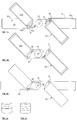
- FIGs. 1a,b are schematic illustrations of embodiments of the present invention showing how the swivel can be provided between a microfluidic chip and a blade of a centrifuge.
- Fig. 1c shows a same centrifuge blade 10 as used in Fig. 1 , the blade 10 having an elongated rectangular shape, that is spun on a center axis 12, therefore providing two centrifuge arms.
- longevity of the centrifuge motor is improved by having a balanced set of arms, and the weight of the blades is typically crucial, so lightweight, strong materials are often used to fabricate the blades, which are typically thin.
- features are provided on each arm for mounting chips to the centrifuge.
- each embodiment is shown in a relaxed state, as it would appear prior to or after centrifugation, and has same structures on each arm to define the swivel, although this is not necessary. Once mounted, the distinction between these swivel placements are largely immaterial, as in any case the assembled chip mount produces an articulated chip holder on the centrifuge that has a controlled drive without a heavy motor or drive equipment for tapping energy from the centrifuge.
- FIG. 1a shows a particular embodiment of the invention in which a two-part centrifuge mount 15 with a contained joint 16 is provided.
- An advantage of this embodiment is that it may be relatively easy to design the centrifuge mount 15 for ready attachment (detachably or otherwise) to an intended variety of centrifuge blades, using the variety of mounting techniques known in the art to provide a suitably secure mounting.
- the swivel mount is provided within mount 15.
- Mount 15 has a blade part 18 and a chip part 20.
- a bottom surface of chip part 20 and top surface 18a of the blade part 18 preferably have a controlled amount of friction.
- a lowest friction may be preferred, and may be provided with a lubrication, or self-lubrication plastics.
- a side wall 18b is provided in the blade part 18 to prevent the chip part 20 from extending beyond alignment with the blade part 18, although in alternative embodiments the side wall 18b may be removed, and the swivel may be designed to rotate about a larger range.
- the chip part 20 has a rectangular recess defined between side walls and a bottom wall for retaining a microfluidic chip of intended dimensions.
- Chip holding features are schematically illustrated, and can be provided by a variety of known devices, or may be omitted, if a drop of water or an inherent high-friction surface interface between the microfluidic chip and the chip part 20 prevents a soft microfluidic chip surface from moving, for example.
- the illustrated set of features include sidewalls and top and bottom end walls, which circumscribe a rectangular chip receiving surface 20a.
- the chip and blade parts 20, 18 are connected by joint 16: an axial revolute joint that may have the form shown in FIG. 2a .
- the joint 16 extends through the chip part at a short distance from the chip receiving area 20a, although many other arrangements of the joint 16 and chip receiving surface can equally be used.
- This embodiment affords an easy view of the elements of the invention, and it is specifically preferred in some embodiments, to provide a rigid support for the chip along a broad surface, if the chip is susceptible to deformation under the centrifugation. In other embodiments, where a larger surface area of the chip is important, it may be preferred to anchor the chip over a relatively small plan area of the chip.
- a force applicator is provided in the form of a looped-wire torsion spring 19, which is fixed to the chip part 20 with arm 19a, and the blade part 18 with the arm 19b.
- the fixing of the arms to edges of the parts may be provided by clamps, sleeves, or adhesives (not shown).
- the force applicator contacts the chip part 20 over a rectangular region that runs tangent to the joint 16.
- the rectangular region subtends an angle of less than 90° from a fixed axis (herein the swivel axis) of joint 16.
- a coil loop of the torsion spring 19 loosely surrounds the joint 16 so that the torsion is applied by the force applicator.
- FIG. 1a One optional feature of FIG. 1a , that may be useful, is a stop 14 that prestresses the torsion spring 19 prior to centrifugation. This allows the chip part 20 to move only once a centripetal force on the chip part 20 overbears the presstress. This may be advantageous for preventing movement of the chip part 20 except during a useful range of accelerations. It will be appreciated that a variety of force applicators can be used to select different forces to be applied at different stages in the movement of the chip part 20 (in orientation or position and orientation) with a single, or with multiple, force applicators.
- the low-friction sliding interface may be provided by suspending chip part 20 so that there is substantially no contact at the interface, whereby the only first order resistance to the pivoting of the chip part is internal to the torsion spring 19, and a negligible resistance internal to the joint 16.
- a loaded chip is placed in the chip receiving area 20a.
- the chip will be loaded with fluid in a plurality of input ports, which may be located at a top of the chip.
- the centrifuge is operated with a pre-defined program, or is controlled in response to detected events on the chip.
- the fluid is drawn by the centrifugal field as constrained by a network of channels within the chip.
- a centre of mass of the chip part 20 and chip i.e. everything supported by the joint 16
- centrifugation rates While a certain minimum centrifugal field is required to consistently draw the fluid, there is typically a wide range of centrifugation rates above the minimum. By operating the centrifuge at rates within this range, an angle of the chip is controlled between a minimum and maximum angle. Depending on a resistance, a variation in mass distribution and inertia, there may be a different amount of hysteresis introduced by a change in centrifugation rate, and accordingly a time may be required for balance to be restored during centrifugation. It may be desirable to establish the actual angle of a system with a given range of loadings at a given sequence of centrifugation rates empirically, and to design optimal operating regimes to achieve a sequence of angles required to perform a protocol, for a given application.
- a maximum angle is typically decided by a location of centre of mass of the chip part 20 (with the chip and any additional weights that may be added to vary this).
- FIG. 1b shows a particular embodiment of the invention in which an articulated centrifuge blade 21 provides the swivel mount. Some centrifuges have replaceable centrifuge blades. It is therefore possible to use an alternative form of blade in these centrifuges. Effectively the articulated blade 21 includes the correspondingly numbered features of FIG. 1a , different in that the blade part 18 is integral with the blade 21, and that side wall 18b and stops 14 are omitted.
- the articulated blade 21 has a force applicator in the form of an extensible spring 22 instead of torsional spring 19.
- the extensible spring 22 is coupled to a blade part 18 of the articulated blade 21 and to the chip part 20. Both of these couplings are effectively at a point, and thus in this embodiment, a small angle is subtended by the attachment to the chip part 20 about the swivel axis.
- mount 15 may be designed to couple to a large variety of centrifuges, whereas articulated blades may be only be designed for a more constrained number of centrifuges, and an advantage of the latter embodiment is less weight is added to the blade.
- FIG. 1c schematically illustrates a third particular embodiment of a swivel mounted chip.
- the whole mount 15 is collapsed to the joint 16, which is attached directly to the blade 10, and to which a chip 25 is mounted.
- the force applicator is provided in the form of two elastic strings 26. Each elastic string 26 extends from a point on a reference chip 25 (i.e. a point that moves relatively little during operation) to a point on the moved chip 25 that is distant the joint 16 on the moved chip.
- the two strings 26 are mounted to the corresponding chips 25, which makes it possible to mount both chips directly to correctly placed joints 16 with convenient pressure fit mountings, or the like, without further mounting of the force applicators, and without having to tension or align the strings 26.
- the other may prevent completely uncoordinated movement of both chips 25, but a change in angles of the chips may show a failure.
- An advantage of the third embodiment is that a light-weight mount is provided, and works well for self-supporting chips 25.
- FIG. 1 shows chips that are initially tilted with respect to the blade (or the blade section of FIG. 1b ), and become straighter with acceleration of the centrifuge, it will be appreciated that this could equally be reversed, for example by changing a position of stop 14 in FIG. 1a , and a length or position of the extensible spring 22, or elastic string 26, in FIGs. 1b ,c.
- FIGs. 2a,b are schematic illustrations of axial revolute joints commonly known in the art. These may have roller bearings, and may have a two part, or three part design as shown. In the embodiment of FIG. 1b it may be particularly inviting to provide two-plane support for a joint 16 such as shown in FIG. 2b , as the mass can be provided at relatively short radius from the center axis, and a stronger, and more resilient bearing is provided.
- FIGs. 3a-d are schematic illustrations of guided joints that may be used in alternative embodiments of the invention.
- FIG. 3a schematically illustrates a revolute joint that consists of three posts in a first part, that extend through three respective slots in a guide piece defined in the second part.
- the first and second parts may be the blade part and the chip part, or vice versa.
- the posts may be rigidly connected together above and below the guide piece for greater resilience.
- the embodiment of FIG. 3a allows for approximately 90° of pivoting.
- An advantage over the revolute joint of FIG. 3a over that of FIG. 2a is that the force is distributed over larger surfaces, and a possible advantage of the axle-based joint is the unlimited angular range.
- the three slots do not have to have a common radius from the axis.
- slots may be of different radii from the axis, so that there is more material between the slots, or the load is distributed over a larger surface.
- FIG. 3b schematically illustrates a revolute joint that consists of one guideway with two interconnected pillars that form a single slider. This joint has similar angular limitations as that of FIG. 3a .
- FIG. 3c schematically illustrates a 1 degree of freedom (DoF) joint that includes three steps: revolution about two axes, and sliding between the two short revolutions.
- DoF 1 degree of freedom
- the pivoting of the chip may allow for a longer effective length of the chip, and if not, may still provide for gating, or valving functions that may be necessary to accomplish some protocols.
- the illustrated 1 DoF joint is shown at an initial (retracted) position if the posts are fixed with the chip, and in a fully extended position if the guideway is fixed with the chip.
- FIG. 3d schematically illustrates a more complicated 1 DoF joint that allows for a number of changes in angle.
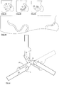
- FIG. 4 schematically illustrates a fourth particular embodiment comprising a non-even number of centrifuge blades (3). It will be appreciated that any number of blades can be provided, subject to the space available of the centrifuge, and an angular extent of the motion of the chip. It is generally preferred to balance the mass distribution around the centrifuge, which is often performed by providing multiple blades (often two or four), although it may also be provided with masses closer to the center axis.
- the fourth embodiment includes dashpots 28 as force applicators. In such embodiments, control can be exerted to slow the descent from a higher potential energy to a lower one, but no restorative force is applied, and accordingly slowing the rate of the centrifuge results in a slowed rate of advance.
- the dashpots may be designed to apply a different resistance as a function of extension, to ensure that, at some angles, the swiveling of the chip parts are impeded, and not as much at other angles. This can allow for improved control over the advance of the swivel throughout an operation, and allowing for coarser control over the revolution rate to effect a given desired predetermined movement of the chip.
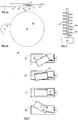
- FIGs. 5a,b are schematic side elevation and plan views of a fifth particular embodiment of the present invention.
- the blade 10 is spun at one end and the chip is rotated about a center axis, unlike the previous examples.
- a disk-shaped chip part 20 is provided for supporting a microfluidic chip.
- the chip part 20 is mounted by an axial revolute joint, which has an axle 30, a cap 31, and one friction pad 32 for meeting the chip part 20, and another friction pad 33 for meeting the blade 10.
- a small motor 34 such as a squiggle motor, or a motor based on piezoelectric, electroactive polymeric, shape memory alloy, or like smart material assemblages is provided that grips the friction pads 32,33 in a low clearance space between the two.
- the small motor 34 can grab the friction pad 32 of the movable chip part 20 close to its centre. Geometrically speaking, a 5 mm displacement of the small motor 34 can produce a 90° pivot movement of the chip part 20 if the motor 34 grabs the friction pad 32 at a radius of less than 5 mm from the swivel axis.
- a controller 36 is provided, for example, for driving the motor 34 in accordance with program instructions and/or communications with an external controller, to perform a protocol for a microfluidic chip. In some embodiments position feedback sensor data, or sensor data pertaining to a monitored flow of fluid in the microfluidic chip, may be received at the controller 36.
- One advantage of the fifth embodiment is a possibility to track an angular position of the chip part 20 during a procedure, for example using sensor data, or feedback from the motor 34, or from the signaling sent to drive or control the motor 34. This may be particularly advantageous when a centrifuge does not have a stroboscope and viewer allowing for visualization of the fluid movement within the chip.
- FIG. 6 is a schematic illustration of another technique for monitoring a degree of extension of a force applicator, applicable to a piston or a spring 40 (as shown).
- the technique involves an instrumented force applicator, which includes a displacement measurement device, which allows for negligibly resisted movement between a telescopic joint defined between inner sleeve 44a and outer sieve 44b.
- An electrical resistance, or other property of a measurement obtained that depends on a degree of the extension is then used to output a signal indicative of the displacement, and therewith, an angle of the chip with respect to the blade.
- the measurement may be made by an autonomous electric circuit with a communications function and power supply in controller 45.
- goniometers e.g. having a retroreflector or mirror on the chip holder for ranging from a static position on a periphery of the centrifuge
- other sensors including stroboscopic imaging of the centrifuge, with image analysis software.
- FIG. 7 schematically illustrates a sequence of steps in operating a centripetally-driven microfluidic chip mounting that uses a spring 22 as a force applicator.
- the mounting has a chip part 20 mounted by an axial revolute joint 16 at a top left corner, and by the spring 22 at a top right corner.
- Step a) shows an angle of the chip part 20 prior to centrifugation. While the illustrated embodiment shows a relaxed spring in a) making an angle of negative 28°, it may be advantageous to provide a higher minimum tension for the spring, as can be provided with a spring that is collinear with the axial revolute joint in a most relaxed position. Such an arrangement reduces an angular variation between step a) and b), and provides a wider range of angles over which the angle can vary by changing a rate of centrifugation.
- Step b) shows a position of the chip part 20 at a minimum centrifugation rate.
- This position is a minimum extension limit (about -9°, as shown) of an angular range over which the chip part 20 varies. It will be appreciated that this limit may be imposed by a minimum centrifugation rate of the centrifuge, or may be a somewhat arbitrary rate chosen for satisfactory movement of the fluid.
- Step d) shows a position of maximum extension: 26°. This position may be determined by a maximum centrifugation rate of the centrifuge, by a burst pressure of the chip, and the angle is always affected by a position of the centre of mass of the chip part 20. The closer the centre of mass of the chip is to the spring 22, the greater a force is applied by the centrifuge.
- Step c) shows an intermediate step where the chip part 20 is aligned with the blade part 18. This position is a reference 0° angle. By varying the centrifuge rate, the chip part 20 can be changed between angles from -9° to 26°. A wide variety of chips and protocols can be designed with such a range in mind.
- FIG. 8 schematically illustrates a sixth particular embodiment of the present invention.
- the force applicator is a compression spring, and bears on the chip part near a bottom of the chip.
- FIG. 9 is a schematic illustration of a seventh particular embodiment of the present invention.
- the force applicator in the seventh embodiment is a planar spiral spring, which is bears on a side of the chip part at two points, whereby a force applied by the planar spiral spring.
- FIGs. 10a,b are schematic illustrations of how a mass can be added to increase an angular range of the chip part. By displacing the centre of mass, with the addition of a mass on an extended arm, the range of the chip can be extended.
- FIG. 10a shows an initial (relaxed) position where the chip part has a 0° angle, and a theoretically greatest angle achievable (where the spring force is considered negligible compared with the centripetal force) of about 103°.
- FIG. 11 is a schematic illustration of an embodiment in which two force applicators are used to provide a two phase application of force.
- an embodiment as shown in FIG. 1b is modified so that the joint 16 has its swivel axis closer to a centre line of the blade, which results in more movement of a square corner of the chip part 20 nearest the center axis.
- the second force applicator which may be a piston or a spring, and may be instrumented.
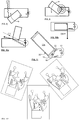
- FIG. 12 schematically illustrates a microfluidic chip 25 tilted at three angles: negative 20°, 0°, and 40°.
- the chip 25 has 6 reservoirs.
- the top 5 reservoirs are shaped so that an egress is at a lowest point, although this is not essential.
- two fully filled top right reservoirs would be disposed for priming. Centrifugation at a constant rate for a prescribed period will allow these two reservoirs to dispense fluid into the bottom right reservoir. No other valve would be in a position to be primed.
- These two top right reservoirs could be filled to a prescribed volume in any manner known in the art, including using the metering and delivery method taught by Applicant in co-pending WO 2013/003935 .
- the fluid volume in the reservoirs materially affects whether a chamber is in a position to be siphoned.
- the metering method of WO 2013/003935 will advantageously allow for control over the volume delivered into these chambers, although that is not shown.
- the bottom right reservoir is a microfluidic mixing chamber, according to the teachings of Applicant's PCT/CA2013/000139 .
- the chip may be moved to a position intermediate the 0° and 40° positions. It will be noted that fully filled chambers in all of the chambers are in a position to be primed and removed at the 40° position, and that each of the chambers has a respective threshold angle between the 0° and 40° positions at which it will prime.
- Protocols typically involve aliquot handling through a series of process steps including sample preparation, filtering, mixing, labelling, incubation, washing, immobilization and analysis; each step requires multiple liquid handling sequences and reactions between biological entities and reagents wherein volumes are moved, mixed or held in place for incubation for a time or until a such as time as they are needed.
- the present invention is able manage simply these sequential process at specific time intervals while holding other reaction volumes stationary until they are required.
- FIG. 13 An example of a centripetally operated swivel mount designed with two chip holders coupled by springs, is imaged in FIG. 13.
- FIGs. 13a-c show the swivel mount having a mass of 50g mounted on a supporting plate by an axial revolute joint.
- FIG. 13a corresponds to a relaxed state of the swivel mount (angle -26°), while b and c show tensioned springs for 0° and 30° rotation angle respectively.
- the swivel mount is formed of a base plate, which is required to support the axial revolute joint, and provides a throughbore for mounting to the centrifuge.
- the base plate has additional features that provide visual cues for identifying the angular disposition of the chip part, and permits additional chips to be mounted to the base plate.
- the joints each couple a respective chip part to the base plate, and the two chip parts are coupled by two coil springs. The fabrication of the base plate and chip parts was performed by additive 3D printing.
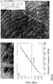
- FIG. 13d shows the calibration curve obtained for the above swivel mount with no mass in the holder. Measurements of this calibration curve with microfluidic chip loads up to 30g of mass show practically no difference with respect to the curve in FIG. 13d , and accordingly this device shows good reproducibility for operation at various angles that depend on rotational rate.
- a considerable advantage of using a spring as a force applicator, is that the path of extension from the initial position to a fully extended position is reversible. That is, the 12 different measurement points corresponding to about 5° intervals between -26° and 34° can be chosen in any order, with minimal durations at intermediate angles, for chosen sequences.
- FIG. 13e Schematics of the fluidic circuitry is shown in the inset.
- the salient features of the design are the siphons linking the reservoirs 2 and 3, 4 and 3 and 5 and 6.
- This was produced from a film of thermoplastic elastomer (specifically, Mediprene OF 400M) that was surface patterned by hot embossing against a mold. The film was applied to a substantially harder Zeonor layer to form a hermetic seal, as per the teachings of Applicant's co-pending US 2011-0085949 .
- the inset on the top right of FIG 13e affords a better view of the patterning of the chip. One can see here a plurality of chambers, including several that were filled.
- a size of the chip part shown in greater detail in FIG. 13e is large enough to support two chips side-by-side. Only one is shown for clarity of illustration. Attachment of the chips has been satisfactory relying only on the friction between the mediprene side of the chip to the chip part, and a raised edge of the chip part that surrounds the chip, although Applicant has also used a clamping mechanism to retain chips in other experiments. Applicant has further stacked a Mediprene side of the chip to a Zeonor side of a bottom chip, to mount two chips vertically. The limits to how many such chips may be stacked for concurrent processing is expected to be limited by the clamping technique used, mass, and dimensions surrounding the centrifuge.
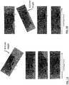
- FIG. 14 shows photographs of the liquid transfer obtained by changing the rotation rate of the platform. From stable equilibrium at negative orientation, in FIG. 14a , the rotation rate is increased to 400 RPM, and held constant for a priming duration, which in the present case was nearly instantaneous. It will be appreciated that by varying a priming duration (e.g. with the introduction of fluid resistances), further flexibilities in an order of dispensing for different chip protocols, can be achieved.
- a priming duration e.g. with the introduction of fluid resistances
- FIG. 15a shows the chip in the same state as in FIG. 14d .
- Subsequent increase of the centrifuge rate to 500 RPM dispensed the metered fluid in chamber 5 into chamber 6, without affecting fluid in any other chambers.
- the rotation rate was slowed again to a 0° angular disposition of the chip.
- FIG. 15b shows the chip with the fluid in chamber 5 moved into chamber 6.
- the centrifugation rate was then increased to 600 RPM to prime reservoir 4, initiating transfer of its content to 3 as shown in FIG. 15 a-d .
- reservoir 5 is then emptied into 6 (not shown here).
- chamber 1 is not affected, showing that appropriate orientation of the siphon angles allows for selective dispensation of some chambers without dispensing other valves.
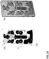
- Fig. 16 shows a top view schematic representation (a) and a photograph (b) of the microfluidic cartridge and its components used in a colorimetric hybridization assay (CHAS) and manipulated with a centrifugal platform based on the principle described in paragraph [0066].
- Compartments 1 and 2 are hybridization units; compartments 3-7 are storage and transfer compartments; and compartment 8 is a waste reservoir. Access ports are labelled as follows: (A) antibody solution; (B) buffer for wash steps; (S) sample; (T) TMB membrane peroxidase substrate, and (V) vents. Orientation of the centrifugal field with respect to the microfluidic cartridge is indicated at the left by the vertical arrow.
- the sensing biological elements are inserted into compartments 1, 2 and the actual detection reaction takes place.
- the cloth chamber (1) is preceded upstream by a buffer chamber (2) that allows for liquid to accumulate before flowing through the cloth, in order to ensure a continuous bubble-free filling of the cloth.
- Compartments 3, 4, 5 and 6 are pre-loaded through ports B3, A, B5, T with specific reactive solutions (respectively, first wash buffer, antibody, second wash buffer and tetramethylbenzidine buffer) while the sample is injected directly in the hybridization chamber through the port S, properly sealed afterwards.
- Additional pillar structures labelled a 3i, 4i, 5i, 6i and 7i are used to hold liquids at pre-defined locations in these chambers when the reactive solutions are loaded to the chip.
- auxiliary vent holes and connecting channels ensure proper circulation of liquids in the microfluidic circuit.
- Liquids from chambers 3 and 7 are triggered by a clockwise rotation of the secondary axis.
- Liquid in compartment 4 is triggered by a counter-clockwise rotation.
- Liquids from 5 and 6 are transferred to the reaction chamber in two steps: (i) a 180 degree flip to move liquids into the reservoirs 3 and 7 and then (ii) angular actuations of the siphons connected to 3 and 7 at a small and large angle, respectively. All liquids are collected in the waste chamber 8 at the end of the reaction.
Landscapes
- Chemical & Material Sciences (AREA)
- Analytical Chemistry (AREA)
- Dispersion Chemistry (AREA)
- Health & Medical Sciences (AREA)
- Clinical Laboratory Science (AREA)
- Chemical Kinetics & Catalysis (AREA)
- Centrifugal Separators (AREA)
- Automatic Analysis And Handling Materials Therefor (AREA)
- Physical Or Chemical Processes And Apparatus (AREA)
Claims (15)
- Montage à puce microfluidique (15) comprenant :une partie de pale (18) de, ou pour le couplage à, une pale (10) d'une centrifugeuse, à une distance radiale d'un axe de la centrifugeuse, la pale (10) étant adaptée pour un montage sur la centrifugeuse (12) à des fins de rotation autour de l'axe, et définissant un plan de la centrifugeuse ; etune partie de puce (20) pour maintenir une puce microfluidique planaire (25) à une orientation ayant une normale étant pas perpendiculaire à l'axe ;caractérisé en ce que le montage à puce microfluidique (15) comprend en outre :un joint à un degré de liberté (DoF) (16) entre la partie de pale (18) et la partie de puce (20), le joint à un DoF (16) permettant à la partie de puce (20) de se déplacer par rapport à la pale de centrifugeuse (10), le mouvement incluant au moins un pivot à 5° projeté sur le plan ;un applicateur de force s'appuyant sur la partie de pale (18) ou l'axe de la centrifugeuse à une extrémité, et la puce ou la partie de puce (20) à une seconde extrémité, l'appui sur la puce ou la partie de puce (20) étant fourni au niveau d'un ensemble fixe d'un ou plusieurs points pour restreindre le mouvement, dans lequel les points fixes n'entourent pas mais sont entourés par n'importe quel centre de rotation à l'instant dans le plan.
- Montage à puce microfluidique (15) selon la revendication 1, dans lequel le mouvement est limité à un changement de position et d'orientation de la puce microfluidique (25) à l'intérieur du plan.
- Montage à puce microfluidique (15) selon la revendication 1, dans lequel : le mouvement est limité au pivotement dans le plan ; ou le joint (16) est un joint rotatif axial (16).
- Montage à puce microfluidique (15) selon la revendication 1, dans lequel le joint (16) comprend au moins deux fonctionnalités guidées et une trajectoire arquée pour les fonctionnalités définissant une voie de guidage, dans lequel la trajectoire arquée inclut au moins un point ayant une courbure contribuant à la définition d'un axe de pivot du joint (16).
- Montage à puce microfluidique (15) selon la revendication 4, dans lequel :deux ou plus des fonctionnalités guidées sont séparées l'une de l'autre ;deux ou plus des fonctionnalités partagent plusieurs contraintes définies par la voie de guidage ;le mouvement inclut le pivotement de la puce dans le plan avec la voix de guidage définissant deux ou plus courbures à des sections différentes ; oule mouvement inclut une translation radiale de la puce par rapport à l'axe de la centrifugeuse, pendant au moins une partie du mouvement.
- Montage à puce microfluidique (15), selon une quelconque des revendications 1-5, dans lequel le joint (16) est prévu :sur une pale (10) de la centrifugeuse ;comme un coupleur entre la puce et la pale de centrifugeuse (10) ; ousur un montage entre la puce et la pale de centrifugeuse (10).
- Montage à puce microfluidique (15), selon une quelconque des revendications 1-6, comprenant en outre un levier, un cliquet ou un assemblage d'outils simples afin de limiter un joint à degrés de liberté multiples (16) au joint á un DoF (16), et/ou définir l'applicateur de force.
- Montage à puce microfluidique (15),selon une quelconque des revendications 1-7, dans lequel la partie de pale est couplée à, ou fait partie de la pale, dans lequel à un moment pendant le mouvement, un centre de masse de la partie de puce (20) et le centre de rotation momentané ne sont pas colinéaires avec l'axe de la centrifugeuse dans le plan projeté, moyennant quoi une force centripète sur la partie de puce (20) entraîne le mouvement, avec une magnitude dépendant d'un taux rotatif de la centrifugeuse (12).
- Montage à puce microfluidique (15), selon une quelconque des revendications 1-8, dans lequel la partie de puce (20) renferme une puce rectangulaire, et dans lequel le mouvement inclut un ensemble de positions et d'orientations momentanées pour lesquelles la longueur de la puce est alignée avec la pale de centrifugeuse (10), et un ensemble de positions et orientations qui sont perpendiculaires à la pale de centrifugeuse (10), dans lequel les positions les plus étendus sont perpendiculaires à la pale de centrifugeuse (10).
- Montage à puce microfluidique (15), selon une quelconque des revendications 1-9, dans lequel l'applicateur de force comprend :une résistance mécanique qui ralentit et contrôle un taux du mouvement;un élément élastique pour résister aux mouvements dans un proportion variable en fonction d'une extension de l'élément élastique ; ouun moteur (34), pouvant être actionné indépendamment de la centrifugeuse (12), le moteur (34) étant un squiggle-moteur, ou un moteur basé sur un actionnement piézo-électrique, à polymère électroactif ou à alliage à mémoire de forme.
- Kit comprenant le montage à puce microfluidique (15) selon la revendication 1, pour définir, une fois assemblé, une pale de centrifugeuse articulée (21) en vue d'un montage d'une puce microfluidique centrifuge planaire (25) sur une centrifugeuse (12).
- Kit selon la revendication 11, dans lequel le montage à puce microfluidique (15) se conforme au montage à puce microfluidique (15) selon une quelconque des revendications 2-10, ou la partie de puce (20) est une de une, deux ou trois parties de puce (20).
- Kit selon la revendication 11 ou 12 comprenant en outre un ou plusieurs de :des instructions d'assemblage de la pale articulée (21) ;des instructions d'assemblage de la pale articulée (21) à partir de deux ou plusieurs parties du kit ;des instructions d'assemblage de la pale articulée (21) à partir d'un nombre prédéfini de pales de centrifugeuse (10) et une ou plusieurs parties du kit ;une ou plusieurs des puces ;des instructions de configuration et de test de la pale articulée (21) une fois assemblée ;des instructions de configuration et de test de la pale articulée (21) une fois assemblée, et une ou plusieurs puces ou dispositif à utiliser pour la configuration et le test de la pale articulée (21) une fois assemblée ; oudes instructions de fonctionnement de la centrifugeuse (12) conformément à un protocole établi sur une puce donnée avec des liquides prescrits chargés dans des chambres respectives de la puce, une fois qu'elle est montée sur la partie de puce (20).
- Procédé de commande d'un angle d'une puce microfluidique planaire centrifuge (25) dans un plan balayé par une centrifugeuse (12) sur laquelle la puce est montée, le procédé comprenant de :fournir une partie de puce (20) montée sur une pale d'une centrifugeuse par un joint à un degré de liberté (DoF) (16) de sorte qu'un support de puce de la partie de puce (20) soit positionné à une distance radiale d'un axe de la centrifugeuse, afin d'être balayé dans un plan de la centrifugeuse par la rotation de la centrifugeuse (12) autour de l'axe ;monter un applicateur de force en restreignant un mouvement de la partie de puce (20) par rapport à la pale en raccordant l'applicateur de force à la partie de pale (18) ou á l'axe de la centrifugeuse à une extrémité, et la puce ou la partie de puce (20) à une seconde extrémité (20) ;placer la puce dans le support de puce de la centrifugeuse (12) de sorte qu'un centre de masse de la partie de puce (20), et l'axe ne soient pas colinéaires avec n'importe quel centre de rotation momentané du joint á un DoF (16) projeté dans le plan, et une normale de la puce n'est pas perpendiculaire à l'axe ; etcommander un taux de rotation de centrifugeuse afin de varier une force centripète momentanée sur la partie de puce (20) fournie par le non-alignement du centre de masse, l'axe et le centre de rotation momentané.
- Procédé selon la revendication 14 :- dans lequel le mouvement est :• limité à une variation de position et d'orientation de la puce microfluidique (25) à l'intérieur du plan ; ou• limité au pivotement dans le plan ;- dans lequel le joint á un DoF (16) :• est un joint rotatif axial (16) ;• comprend au moins deux fonctionnalités guidées et une trajectoire arquée pour les fonctionnalités définissant une voie de passage, dans lequel la trajectoire arquée inclut au moins un point ayant une courbure contribuant à la définition d'un axe de pivot du joint (16) ; ou• est prévu :∘ sur une pale de la centrifugeuse ;∘ comme un coupleur entre la puce et la pale de centrifugeuse (10) ; ou∘ sur un montage entre la puce et la pale de centrifugeuse (10) ;- dans lequel l'applicateur de force comprend en outre un levier, un cliquet ou un assemblage d'outils simples afin de limiter un joint à degrés de liberté multiples (16) au joint á un DoF (16), et/ou de définir l'applicateur de force du joint á un DoF (16) ; ou- dans lequel l'applicateur de force comprend :• une résistance mécanique qui ralentit et contrôle un taux du mouvement ;• un élément élastique pour résister aux mouvements dans une proportion variable en fonction d'une extension de l'élément élastique ; ou• un moteur (34), pouvant être actionné indépendamment de la centrifugeuse (12), le moteur (34) étant un squiggle-moteur, ou un moteur basé sur un actionnement piézo-électrique, à polymère électroactif ou à alliage à mémoire de forme.
Applications Claiming Priority (2)
| Application Number | Priority Date | Filing Date | Title |
|---|---|---|---|
| US201462002984P | 2014-05-26 | 2014-05-26 | |
| PCT/IB2015/053934 WO2015181725A1 (fr) | 2014-05-26 | 2015-05-26 | Monture sur pivot pour puce microfluidique centrifuge |
Publications (3)
| Publication Number | Publication Date |
|---|---|
| EP3148702A1 EP3148702A1 (fr) | 2017-04-05 |
| EP3148702A4 EP3148702A4 (fr) | 2017-12-20 |
| EP3148702B1 true EP3148702B1 (fr) | 2020-01-01 |
Family
ID=54698206
Family Applications (1)
| Application Number | Title | Priority Date | Filing Date |
|---|---|---|---|
| EP15800407.7A Active EP3148702B1 (fr) | 2014-05-26 | 2015-05-26 | Monture sur pivot pour puce microfluidique centrifuge |
Country Status (7)
| Country | Link |
|---|---|
| US (1) | US11071985B2 (fr) |
| EP (1) | EP3148702B1 (fr) |
| KR (1) | KR102588025B1 (fr) |
| AU (2) | AU2015265539B2 (fr) |
| CA (1) | CA2950245C (fr) |
| ES (1) | ES2781862T3 (fr) |
| WO (1) | WO2015181725A1 (fr) |
Families Citing this family (8)
| Publication number | Priority date | Publication date | Assignee | Title |
|---|---|---|---|---|
| CN107305211A (zh) | 2016-04-20 | 2017-10-31 | 光宝电子(广州)有限公司 | 液体分析装置 |
| CN109564231B (zh) | 2016-06-08 | 2023-01-06 | 加利福尼亚大学董事会 | 用于处理组织和细胞的方法和装置 |
| KR101974587B1 (ko) * | 2017-08-16 | 2019-05-02 | (주)오상헬스케어 | 유전자 분석 장치용 카트리지 및 이를 포함하는 유전자 분석 장치 |
| CN107703062B (zh) * | 2017-11-10 | 2024-06-14 | 邵建波 | 一种实时观测离心式微流控芯片的方法及装置 |
| CA3119623A1 (fr) * | 2018-11-13 | 2020-05-22 | National Research Council Of Canada | Interface automatisee monde/puce pour plateformes microfluidiques centrifuges |
| JP2022538389A (ja) * | 2019-06-28 | 2022-09-02 | ナショナル リサーチ カウンシル オブ カナダ | 遠心マイクロ流体チップ、キットおよびオンチップガス供給システム |
| US20210001344A1 (en) * | 2019-07-03 | 2021-01-07 | Shimadzu Corporation | Sample holding disc for centrifugation |
| CN114323850B (zh) * | 2021-12-22 | 2024-02-13 | 上海锐翌生物科技有限公司 | 样本前处理装置以及核酸与粪便样本前处理方法 |
Family Cites Families (17)
| Publication number | Priority date | Publication date | Assignee | Title |
|---|---|---|---|---|
| US4468410A (en) * | 1982-08-18 | 1984-08-28 | Immunomed Corp. | Method and apparatus for producing a microscopic specimen slide |
| US4814282A (en) | 1984-05-03 | 1989-03-21 | Abbott Laboratories | Centrifuge for two-dimensional centrifugation |
| US4776832A (en) | 1985-03-21 | 1988-10-11 | Abbott Laboratories | Centrifuge having multiple induction motors for rotating objects about a second axis |
| US4892708A (en) | 1987-07-01 | 1990-01-09 | Miles Inc. | Fluid separation and processing device |
| US20020155590A1 (en) | 2001-04-24 | 2002-10-24 | Dade Behring Inc. | Canister for inventorying susceptability test devices in an automated microbiological analyzer |
| AU2002365278A1 (en) | 2001-12-20 | 2003-07-09 | Radius Biosciences | Centrifugal array processing device |
| WO2003083491A2 (fr) * | 2002-03-25 | 2003-10-09 | Centrifluidics, Inc. | Procede et appareil de controle du mouvement des fluides dans un systeme microfluidique |
| US20050026301A1 (en) | 2002-03-25 | 2005-02-03 | Henry Petithory | Method and apparatus for controlling fluid movement in a microfluidic system |
| JP2006110523A (ja) * | 2004-10-18 | 2006-04-27 | Hitachi Software Eng Co Ltd | 化学反応装置 |
| JP4901333B2 (ja) | 2006-06-30 | 2012-03-21 | ローム株式会社 | マイクロチップ検査装置 |
| JP4978892B2 (ja) * | 2007-12-12 | 2012-07-18 | セイコーエプソン株式会社 | 生体物質検出装置、反応用チップ、および生体物質検出方法 |
| KR20100039707A (ko) | 2008-10-08 | 2010-04-16 | 삼성전자주식회사 | 빔 발사 장치, 상기 빔 발사 장치를 구비한 생화학 분석기,및 상기 생화학 분석기를 구비한 생화학 분석 시스템 |
| US8491454B2 (en) | 2008-12-02 | 2013-07-23 | President And Fellows Of Harvard College | Spinning force apparatus |
| US9238346B2 (en) | 2009-10-08 | 2016-01-19 | National Research Council Of Canada | Microfluidic device, composition and method of forming |
| NO333558B1 (no) | 2009-12-29 | 2013-07-08 | Stiftelsen Sintef | Sentrifugeanordning, bruk av en slik anordning og fremgangsmåte for sentrifugering |
| AU2012278872A1 (en) | 2011-07-04 | 2014-02-06 | National Research Council Of Canada | Centrifugal microfluidic platform |
| CA2864641C (fr) | 2012-02-16 | 2021-05-04 | National Research Council Of Canada | Appareil et procede de melange centrifuge microfluidique |
-
2015
- 2015-05-26 EP EP15800407.7A patent/EP3148702B1/fr active Active
- 2015-05-26 AU AU2015265539A patent/AU2015265539B2/en not_active Ceased
- 2015-05-26 WO PCT/IB2015/053934 patent/WO2015181725A1/fr not_active Ceased
- 2015-05-26 ES ES15800407T patent/ES2781862T3/es active Active
- 2015-05-26 CA CA2950245A patent/CA2950245C/fr active Active
- 2015-05-26 US US15/313,961 patent/US11071985B2/en active Active
- 2015-05-26 KR KR1020167036251A patent/KR102588025B1/ko active Active
-
2020
- 2020-04-16 AU AU2020202593A patent/AU2020202593B2/en not_active Ceased
Non-Patent Citations (1)
| Title |
|---|
| None * |
Also Published As
| Publication number | Publication date |
|---|---|
| WO2015181725A1 (fr) | 2015-12-03 |
| AU2020202593B2 (en) | 2021-07-29 |
| EP3148702A4 (fr) | 2017-12-20 |
| AU2020202593A1 (en) | 2020-05-07 |
| EP3148702A1 (fr) | 2017-04-05 |
| ES2781862T3 (es) | 2020-09-08 |
| AU2015265539A1 (en) | 2017-01-05 |
| US20170173589A1 (en) | 2017-06-22 |
| US11071985B2 (en) | 2021-07-27 |
| KR102588025B1 (ko) | 2023-10-11 |
| CA2950245C (fr) | 2023-08-01 |
| KR20170008308A (ko) | 2017-01-23 |
| CA2950245A1 (fr) | 2015-12-03 |
| AU2015265539B2 (en) | 2020-01-16 |
Similar Documents
| Publication | Publication Date | Title |
|---|---|---|
| AU2020202593B2 (en) | Swivel mount for centrifugal microfluidic chip | |
| Clime et al. | Active pumping and control of flows in centrifugal microfluidics | |
| Madou et al. | LabCD: a centrifuge-based microfluidic platform for diagnostics | |
| US8534319B2 (en) | Serial siphon valves for fluidic or microfluidic devices | |
| EP1284818B1 (fr) | Dispositifs microfluidiques centrifuges a ecoulement bidirectionnel | |
| Cai et al. | A magnetically actuated valve for centrifugal microfluidic applications | |
| US20170036208A1 (en) | Centrifugal microfluidic chip control | |
| Aeinehvand et al. | Reversible thermo-pneumatic valves on centrifugal microfluidic platforms | |
| US20140134631A1 (en) | Centrifugal microfluidic platform | |
| US20020142470A1 (en) | Directional acceleration vector-driven displacement of fluids (DAVD-DOF) | |
| US10166541B2 (en) | Centrifugal microfluidic platform for automated media exchange | |
| US20220008924A1 (en) | World-to-chip automated interface for centrifugal microfluidic platforms | |
| WO2018099922A1 (fr) | Dispositif fluidique d'aliquotage et de mélange combinatoire de liquides | |
| EP3236266B1 (fr) | Dispositif d'analyse de liquides | |
| WO2014003535A1 (fr) | Dispositif microfluidique | |
| CN104507576B (zh) | 用于试剂容器的旋转部件,试剂容器部件和用于离心分离机和/或用于压力改变装置的试剂容器 | |
| CA2158721A1 (fr) | Methode et installation pour stocker et melanger plusieurs fluides et cartouche d'echantillonnage de liquides organiques utilisee a ces fins | |
| Ibrahim et al. | Analysis and experiment of centrifugal force for microfluidic ELISA CD platform | |
| Soroori et al. | Centrifugal microfluidics: characteristics and possibilities | |
| TWI777356B (zh) | 生物檢測系統及生物檢測裝置 | |
| Aeinehvand et al. | The effects of placement and geometry on thermo-pneumatic pumping on centrifugal microfluidic compact disc (CD) platforms | |
| US20190024648A1 (en) | Architecture for a system of integrated pumps, mixers, and gates for microfluidic devices | |
| Aeinehvand | Reversible Microballoon System for Handling Bioanalytical Assays on Centrifugal Microfluidic Platform |
Legal Events
| Date | Code | Title | Description |
|---|---|---|---|
| STAA | Information on the status of an ep patent application or granted ep patent |
Free format text: STATUS: THE INTERNATIONAL PUBLICATION HAS BEEN MADE |
|
| PUAI | Public reference made under article 153(3) epc to a published international application that has entered the european phase |
Free format text: ORIGINAL CODE: 0009012 |
|
| STAA | Information on the status of an ep patent application or granted ep patent |
Free format text: STATUS: REQUEST FOR EXAMINATION WAS MADE |
|
| 17P | Request for examination filed |
Effective date: 20170102 |
|
| AK | Designated contracting states |
Kind code of ref document: A1 Designated state(s): AL AT BE BG CH CY CZ DE DK EE ES FI FR GB GR HR HU IE IS IT LI LT LU LV MC MK MT NL NO PL PT RO RS SE SI SK SM TR |
|
| AX | Request for extension of the european patent |
Extension state: BA ME |
|
| DAV | Request for validation of the european patent (deleted) | ||
| DAX | Request for extension of the european patent (deleted) | ||
| A4 | Supplementary search report drawn up and despatched |
Effective date: 20171117 |
|
| RIC1 | Information provided on ipc code assigned before grant |
Ipc: B01L 9/00 20060101AFI20171113BHEP Ipc: G01N 35/00 20060101ALN20171113BHEP Ipc: B04B 5/04 20060101ALI20171113BHEP |
|
| STAA | Information on the status of an ep patent application or granted ep patent |
Free format text: STATUS: EXAMINATION IS IN PROGRESS |
|
| 17Q | First examination report despatched |
Effective date: 20180720 |
|
| REG | Reference to a national code |
Ref country code: DE Ref legal event code: R079 Ref document number: 602015044803 Country of ref document: DE Free format text: PREVIOUS MAIN CLASS: B04B0015000000 Ipc: B01L0009000000 |
|
| GRAP | Despatch of communication of intention to grant a patent |
Free format text: ORIGINAL CODE: EPIDOSNIGR1 |
|
| STAA | Information on the status of an ep patent application or granted ep patent |
Free format text: STATUS: GRANT OF PATENT IS INTENDED |
|
| RIC1 | Information provided on ipc code assigned before grant |
Ipc: G01N 35/00 20060101ALN20190611BHEP Ipc: B01L 9/00 20060101AFI20190611BHEP Ipc: B04B 5/04 20060101ALI20190611BHEP |
|
| RIC1 | Information provided on ipc code assigned before grant |
Ipc: B04B 5/04 20060101ALI20190628BHEP Ipc: G01N 35/00 20060101ALN20190628BHEP Ipc: B01L 9/00 20060101AFI20190628BHEP |
|
| INTG | Intention to grant announced |
Effective date: 20190716 |
|
| GRAS | Grant fee paid |
Free format text: ORIGINAL CODE: EPIDOSNIGR3 |
|
| GRAA | (expected) grant |
Free format text: ORIGINAL CODE: 0009210 |
|
| STAA | Information on the status of an ep patent application or granted ep patent |
Free format text: STATUS: THE PATENT HAS BEEN GRANTED |
|
| AK | Designated contracting states |
Kind code of ref document: B1 Designated state(s): AL AT BE BG CH CY CZ DE DK EE ES FI FR GB GR HR HU IE IS IT LI LT LU LV MC MK MT NL NO PL PT RO RS SE SI SK SM TR |
|
| REG | Reference to a national code |
Ref country code: GB Ref legal event code: FG4D |
|
| REG | Reference to a national code |
Ref country code: CH Ref legal event code: EP Ref country code: AT Ref legal event code: REF Ref document number: 1219094 Country of ref document: AT Kind code of ref document: T Effective date: 20200115 |
|
| REG | Reference to a national code |
Ref country code: IE Ref legal event code: FG4D |
|
| REG | Reference to a national code |
Ref country code: DE Ref legal event code: R096 Ref document number: 602015044803 Country of ref document: DE |
|
| REG | Reference to a national code |
Ref country code: NL Ref legal event code: MP Effective date: 20200101 |
|
| REG | Reference to a national code |
Ref country code: LT Ref legal event code: MG4D |
|
| PG25 | Lapsed in a contracting state [announced via postgrant information from national office to epo] |
Ref country code: RS Free format text: LAPSE BECAUSE OF FAILURE TO SUBMIT A TRANSLATION OF THE DESCRIPTION OR TO PAY THE FEE WITHIN THE PRESCRIBED TIME-LIMIT Effective date: 20200101 Ref country code: NO Free format text: LAPSE BECAUSE OF FAILURE TO SUBMIT A TRANSLATION OF THE DESCRIPTION OR TO PAY THE FEE WITHIN THE PRESCRIBED TIME-LIMIT Effective date: 20200401 Ref country code: FI Free format text: LAPSE BECAUSE OF FAILURE TO SUBMIT A TRANSLATION OF THE DESCRIPTION OR TO PAY THE FEE WITHIN THE PRESCRIBED TIME-LIMIT Effective date: 20200101 Ref country code: LT Free format text: LAPSE BECAUSE OF FAILURE TO SUBMIT A TRANSLATION OF THE DESCRIPTION OR TO PAY THE FEE WITHIN THE PRESCRIBED TIME-LIMIT Effective date: 20200101 Ref country code: CZ Free format text: LAPSE BECAUSE OF FAILURE TO SUBMIT A TRANSLATION OF THE DESCRIPTION OR TO PAY THE FEE WITHIN THE PRESCRIBED TIME-LIMIT Effective date: 20200101 Ref country code: NL Free format text: LAPSE BECAUSE OF FAILURE TO SUBMIT A TRANSLATION OF THE DESCRIPTION OR TO PAY THE FEE WITHIN THE PRESCRIBED TIME-LIMIT Effective date: 20200101 Ref country code: PT Free format text: LAPSE BECAUSE OF FAILURE TO SUBMIT A TRANSLATION OF THE DESCRIPTION OR TO PAY THE FEE WITHIN THE PRESCRIBED TIME-LIMIT Effective date: 20200527 |
|
| PG25 | Lapsed in a contracting state [announced via postgrant information from national office to epo] |
Ref country code: SE Free format text: LAPSE BECAUSE OF FAILURE TO SUBMIT A TRANSLATION OF THE DESCRIPTION OR TO PAY THE FEE WITHIN THE PRESCRIBED TIME-LIMIT Effective date: 20200101 Ref country code: GR Free format text: LAPSE BECAUSE OF FAILURE TO SUBMIT A TRANSLATION OF THE DESCRIPTION OR TO PAY THE FEE WITHIN THE PRESCRIBED TIME-LIMIT Effective date: 20200402 Ref country code: IS Free format text: LAPSE BECAUSE OF FAILURE TO SUBMIT A TRANSLATION OF THE DESCRIPTION OR TO PAY THE FEE WITHIN THE PRESCRIBED TIME-LIMIT Effective date: 20200501 Ref country code: LV Free format text: LAPSE BECAUSE OF FAILURE TO SUBMIT A TRANSLATION OF THE DESCRIPTION OR TO PAY THE FEE WITHIN THE PRESCRIBED TIME-LIMIT Effective date: 20200101 Ref country code: HR Free format text: LAPSE BECAUSE OF FAILURE TO SUBMIT A TRANSLATION OF THE DESCRIPTION OR TO PAY THE FEE WITHIN THE PRESCRIBED TIME-LIMIT Effective date: 20200101 Ref country code: BG Free format text: LAPSE BECAUSE OF FAILURE TO SUBMIT A TRANSLATION OF THE DESCRIPTION OR TO PAY THE FEE WITHIN THE PRESCRIBED TIME-LIMIT Effective date: 20200401 |
|
| REG | Reference to a national code |
Ref country code: ES Ref legal event code: FG2A Ref document number: 2781862 Country of ref document: ES Kind code of ref document: T3 Effective date: 20200908 |
|
| REG | Reference to a national code |
Ref country code: DE Ref legal event code: R097 Ref document number: 602015044803 Country of ref document: DE |
|
| PG25 | Lapsed in a contracting state [announced via postgrant information from national office to epo] |
Ref country code: EE Free format text: LAPSE BECAUSE OF FAILURE TO SUBMIT A TRANSLATION OF THE DESCRIPTION OR TO PAY THE FEE WITHIN THE PRESCRIBED TIME-LIMIT Effective date: 20200101 Ref country code: SK Free format text: LAPSE BECAUSE OF FAILURE TO SUBMIT A TRANSLATION OF THE DESCRIPTION OR TO PAY THE FEE WITHIN THE PRESCRIBED TIME-LIMIT Effective date: 20200101 Ref country code: RO Free format text: LAPSE BECAUSE OF FAILURE TO SUBMIT A TRANSLATION OF THE DESCRIPTION OR TO PAY THE FEE WITHIN THE PRESCRIBED TIME-LIMIT Effective date: 20200101 Ref country code: DK Free format text: LAPSE BECAUSE OF FAILURE TO SUBMIT A TRANSLATION OF THE DESCRIPTION OR TO PAY THE FEE WITHIN THE PRESCRIBED TIME-LIMIT Effective date: 20200101 Ref country code: SM Free format text: LAPSE BECAUSE OF FAILURE TO SUBMIT A TRANSLATION OF THE DESCRIPTION OR TO PAY THE FEE WITHIN THE PRESCRIBED TIME-LIMIT Effective date: 20200101 |
|
| PLBE | No opposition filed within time limit |
Free format text: ORIGINAL CODE: 0009261 |
|
| STAA | Information on the status of an ep patent application or granted ep patent |
Free format text: STATUS: NO OPPOSITION FILED WITHIN TIME LIMIT |
|
| REG | Reference to a national code |
Ref country code: AT Ref legal event code: MK05 Ref document number: 1219094 Country of ref document: AT Kind code of ref document: T Effective date: 20200101 |
|
| 26N | No opposition filed |
Effective date: 20201002 |
|
| PG25 | Lapsed in a contracting state [announced via postgrant information from national office to epo] |
Ref country code: MC Free format text: LAPSE BECAUSE OF FAILURE TO SUBMIT A TRANSLATION OF THE DESCRIPTION OR TO PAY THE FEE WITHIN THE PRESCRIBED TIME-LIMIT Effective date: 20200101 Ref country code: LI Free format text: LAPSE BECAUSE OF NON-PAYMENT OF DUE FEES Effective date: 20200531 Ref country code: CH Free format text: LAPSE BECAUSE OF NON-PAYMENT OF DUE FEES Effective date: 20200531 Ref country code: AT Free format text: LAPSE BECAUSE OF FAILURE TO SUBMIT A TRANSLATION OF THE DESCRIPTION OR TO PAY THE FEE WITHIN THE PRESCRIBED TIME-LIMIT Effective date: 20200101 |
|
| PG25 | Lapsed in a contracting state [announced via postgrant information from national office to epo] |
Ref country code: SI Free format text: LAPSE BECAUSE OF FAILURE TO SUBMIT A TRANSLATION OF THE DESCRIPTION OR TO PAY THE FEE WITHIN THE PRESCRIBED TIME-LIMIT Effective date: 20200101 Ref country code: PL Free format text: LAPSE BECAUSE OF FAILURE TO SUBMIT A TRANSLATION OF THE DESCRIPTION OR TO PAY THE FEE WITHIN THE PRESCRIBED TIME-LIMIT Effective date: 20200101 |
|
| REG | Reference to a national code |
Ref country code: BE Ref legal event code: MM Effective date: 20200531 |
|
| PG25 | Lapsed in a contracting state [announced via postgrant information from national office to epo] |
Ref country code: LU Free format text: LAPSE BECAUSE OF NON-PAYMENT OF DUE FEES Effective date: 20200526 |
|
| PG25 | Lapsed in a contracting state [announced via postgrant information from national office to epo] |
Ref country code: IE Free format text: LAPSE BECAUSE OF NON-PAYMENT OF DUE FEES Effective date: 20200526 |
|
| PG25 | Lapsed in a contracting state [announced via postgrant information from national office to epo] |
Ref country code: BE Free format text: LAPSE BECAUSE OF NON-PAYMENT OF DUE FEES Effective date: 20200531 |
|
| PG25 | Lapsed in a contracting state [announced via postgrant information from national office to epo] |
Ref country code: TR Free format text: LAPSE BECAUSE OF FAILURE TO SUBMIT A TRANSLATION OF THE DESCRIPTION OR TO PAY THE FEE WITHIN THE PRESCRIBED TIME-LIMIT Effective date: 20200101 Ref country code: MT Free format text: LAPSE BECAUSE OF FAILURE TO SUBMIT A TRANSLATION OF THE DESCRIPTION OR TO PAY THE FEE WITHIN THE PRESCRIBED TIME-LIMIT Effective date: 20200101 Ref country code: CY Free format text: LAPSE BECAUSE OF FAILURE TO SUBMIT A TRANSLATION OF THE DESCRIPTION OR TO PAY THE FEE WITHIN THE PRESCRIBED TIME-LIMIT Effective date: 20200101 |
|
| PG25 | Lapsed in a contracting state [announced via postgrant information from national office to epo] |
Ref country code: MK Free format text: LAPSE BECAUSE OF FAILURE TO SUBMIT A TRANSLATION OF THE DESCRIPTION OR TO PAY THE FEE WITHIN THE PRESCRIBED TIME-LIMIT Effective date: 20200101 Ref country code: AL Free format text: LAPSE BECAUSE OF FAILURE TO SUBMIT A TRANSLATION OF THE DESCRIPTION OR TO PAY THE FEE WITHIN THE PRESCRIBED TIME-LIMIT Effective date: 20200101 |
|
| PGFP | Annual fee paid to national office [announced via postgrant information from national office to epo] |
Ref country code: ES Payment date: 20240627 Year of fee payment: 10 |
|
| PGFP | Annual fee paid to national office [announced via postgrant information from national office to epo] |
Ref country code: IT Payment date: 20240524 Year of fee payment: 10 |
|
| PGFP | Annual fee paid to national office [announced via postgrant information from national office to epo] |
Ref country code: DE Payment date: 20250326 Year of fee payment: 11 |
|
| PGFP | Annual fee paid to national office [announced via postgrant information from national office to epo] |
Ref country code: GB Payment date: 20250521 Year of fee payment: 11 |
|
| PGFP | Annual fee paid to national office [announced via postgrant information from national office to epo] |
Ref country code: FR Payment date: 20250528 Year of fee payment: 11 |
|
| PG25 | Lapsed in a contracting state [announced via postgrant information from national office to epo] |
Ref country code: IT Free format text: LAPSE BECAUSE OF NON-PAYMENT OF DUE FEES Effective date: 20250526 |