EP3148717B1 - Behandlungsverfahren und vorrichtung mit einem verdichteten fluid und einem ausstossspeichervolumen - Google Patents
Behandlungsverfahren und vorrichtung mit einem verdichteten fluid und einem ausstossspeichervolumen Download PDFInfo
- Publication number
- EP3148717B1 EP3148717B1 EP15726119.9A EP15726119A EP3148717B1 EP 3148717 B1 EP3148717 B1 EP 3148717B1 EP 15726119 A EP15726119 A EP 15726119A EP 3148717 B1 EP3148717 B1 EP 3148717B1
- Authority
- EP
- European Patent Office
- Prior art keywords
- chamber
- storage means
- fluid
- treatment
- gas
- Prior art date
- Legal status (The legal status is an assumption and is not a legal conclusion. Google has not performed a legal analysis and makes no representation as to the accuracy of the status listed.)
- Not-in-force
Links
Images


Classifications
-
- B—PERFORMING OPERATIONS; TRANSPORTING
- B08—CLEANING
- B08B—CLEANING IN GENERAL; PREVENTION OF FOULING IN GENERAL
- B08B7/00—Cleaning by methods not provided for in a single other subclass or a single group in this subclass
- B08B7/0021—Cleaning by methods not provided for in a single other subclass or a single group in this subclass by liquid gases or supercritical fluids
-
- B—PERFORMING OPERATIONS; TRANSPORTING
- B01—PHYSICAL OR CHEMICAL PROCESSES OR APPARATUS IN GENERAL
- B01J—CHEMICAL OR PHYSICAL PROCESSES, e.g. CATALYSIS OR COLLOID CHEMISTRY; THEIR RELEVANT APPARATUS
- B01J3/00—Processes of utilising sub-atmospheric or super-atmospheric pressure to effect chemical or physical change of matter; Apparatus therefor
- B01J3/04—Pressure vessels, e.g. autoclaves
-
- B—PERFORMING OPERATIONS; TRANSPORTING
- B08—CLEANING
- B08B—CLEANING IN GENERAL; PREVENTION OF FOULING IN GENERAL
- B08B3/00—Cleaning by methods involving the use or presence of liquid or steam
- B08B3/02—Cleaning by the force of jets or sprays
-
- B—PERFORMING OPERATIONS; TRANSPORTING
- B08—CLEANING
- B08B—CLEANING IN GENERAL; PREVENTION OF FOULING IN GENERAL
- B08B3/00—Cleaning by methods involving the use or presence of liquid or steam
- B08B3/04—Cleaning involving contact with liquid
- B08B3/045—Cleaning involving contact with liquid using perforated containers, e.g. baskets, or racks immersed and agitated in a liquid bath
-
- H—ELECTRICITY
- H10—SEMICONDUCTOR DEVICES; ELECTRIC SOLID-STATE DEVICES NOT OTHERWISE PROVIDED FOR
- H10P—GENERIC PROCESSES OR APPARATUS FOR THE MANUFACTURE OR TREATMENT OF DEVICES COVERED BY CLASS H10
- H10P70/00—Cleaning of wafers, substrates or parts of devices
- H10P70/80—Cleaning only by supercritical fluids
-
- H—ELECTRICITY
- H10—SEMICONDUCTOR DEVICES; ELECTRIC SOLID-STATE DEVICES NOT OTHERWISE PROVIDED FOR
- H10P—GENERIC PROCESSES OR APPARATUS FOR THE MANUFACTURE OR TREATMENT OF DEVICES COVERED BY CLASS H10
- H10P72/00—Handling or holding of wafers, substrates or devices during manufacture or treatment thereof
- H10P72/04—Apparatus for manufacture or treatment
- H10P72/0402—Apparatus for fluid treatment
- H10P72/0406—Apparatus for fluid treatment for cleaning followed by drying, rinsing, stripping, blasting or the like
- H10P72/0411—Apparatus for fluid treatment for cleaning followed by drying, rinsing, stripping, blasting or the like for wet cleaning or washing
- H10P72/0414—Apparatus for fluid treatment for cleaning followed by drying, rinsing, stripping, blasting or the like for wet cleaning or washing using mainly spraying means, e.g. nozzles
Definitions
- the invention relates to processing techniques, in particular extraction, for example cleaning, parts or objects by implementation of a dense fluid, for example super critical, including carbon dioxide.
- a dense fluid for example super critical, including carbon dioxide.
- a cleaning technique is known from the document WO 02/32593-A1 and document US 2004/023170-A17 , which is considered the state of the art closest to the invention.
- This device is fed with a liquefied gas, which comes for example from a reserve, or bottle, 2, in which it is maintained at a temperature of, for example, -20 ° C.
- This reserve 2 makes it possible to feed a storage chamber 6, which stores both gaseous gas and liquefied gas, via a pump 3 or a filling compressor and a valve 6 1 .
- the gas is heated by heating means 7, which will increase its temperature, for example to 20 ° C, and bring it to a pressure of several tens of bar, for example about 60 bar .
- Liquefied gas taken from this chamber 6 by means of a valve 6 3 , can then be carried, by means 8, under thermodynamic conditions allowing it to be used as a cleaning fluid in the enclosure cleaning 14, also called autoclave.
- the means 8 can comprise pumping means 10 and heating means 12.
- the pump 10 can carry the fluid from the reserve 6 to a pressure greater than 73 , 85 bars, and the heating means 12 make it possible to raise the temperature of the fluid to a value greater than 31 ° C., these conditions assuring the fluid a super critical state.
- the fluid can be used in accordance with the teaching of the document WO 02/32193 .
- the autoclave 14 is provided with a door 15 which will allow to introduce the parts to be cleaned. After closing the door, the fluid is introduced under pressure, at about 120 bar, and the parts are cleaned by the action of the fluid.
- the fluid is then discharged, expanded by expansion means 16 (mainly comprising a control valve 16 2 and a valve 16 1 ), then sent to means 18 forming a separator, which will allow to separate the gas particles and soils that have been recovered during cleaning and the gas is charged.
- expansion means 16 mainly comprising a control valve 16 2 and a valve 16 1
- the gas thus treated can then be fed to liquefaction means 19 and then stored again in liquid form in enclosure 6.
- a cleaning cycle implemented with this type of device is too long for implementation on a truly industrial scale.
- a valve 6 2 is disposed on a path defined by a conduit 9 which connects an upper portion of the enclosure 6 and a point disposed between the pump 10 and the heating means 12. This valve and this duct make it possible to take gas, in gaseous form. This gas is then heated by the means 12. If it is not desired to heat the gas, it is possible for the means 9 to be connected directly to the means 27 or even directly to the means 14.
- This step allows, when the dense fluid gas is then introduced, under pressure, from the means 8, to prevent it from being under conditions that can lead to the formation of a block of ice (this is the phenomenon, in the case of the dioxide of carbon, dry ice formation; indeed, the triple point of CO 2 is at -56 ° C, 5 bar), which is to be avoided because this ice can be very difficult to eliminate quickly.
- the door 15 (or the valve 14 2 ) of the chamber 14 is open, and the gas contained in the latter is sent into the atmosphere. This results in a significant loss of this gas.
- the invention aims to solve these problems by a dense fluid treatment device according to claim 1 and a corresponding dense fluid treatment method according to claim 10.
- a first fluid flow will therefore flow from the treatment chamber to said second storage means, then, conversely, in a path opposite to that followed by the first flow, a second fluid flow will flow from the second storage means to the treatment chamber.
- This circulation will be done by pressure difference between the 2 volumes concerned: when the pressure in the treatment chamber is greater than that in the second storage means, the fluid flows from the treatment chamber to the second storage means; when the pressure in the treatment chamber is lower than that in the second storage means, the fluid flows from the second storage means to the treatment chamber.
- Means are specially programmed to circulate a fluid from the treatment chamber to said second storage means, and vice versa, second storage means to the treatment chamber.
- the second storage means can store, at a pressure P 2 , a portion of the gas which is contained in the pressure treatment chamber P 1 (P 1 > P 2 ), after a processing step and before putting in communication fluidic of the interior of the chamber and the outside atmosphere, in particular by opening the door of the chamber and before setting in fluid communication of the treatment chamber with the storage means.
- fluid communication applying to 2 volumes, means that a fluid can flow, or flow, from one volume to another.
- the means for setting fluid communication are also means for interrupting this fluid communication, that is to say to stop any possibility of fluid flow from one volume to another.
- the transfer of gas between the second storage means and the treatment chamber, in one direction or the other, is carried out using the means for setting fluid communication, for example by opening one or more said valves.
- This transfer is performed without pumping means, under the simple action of the pressure in the two volumes in communication, for example until balancing the pressures between these 2 volumes.
- the invention allows a recovery of a portion of the gas used, without energy supply, and without moving parts, except the valves.
- the second storage means are different from the first storage means. They may also be different from the first storage means by their volume, and / or the pressure at which the gases are stored therein ... etc.
- the second storage means then allow reuse of the stored gas for various applications.
- this step it actuates the fluid communication means, as indicated above.
- the pressure in the treatment chamber then increases, from the atmospheric pressure to a pressure P 3 , lower than the pressure P 2 of storage in the second storage means, while the pressure in the second storage means decreases from the storage pressure P 2 to, for example, the pressure P 3 .
- This gas filling of the autoclave, at the beginning of the cleaning cycle, can be very fast.
- this fluid thus stored can be used to actuate at least a portion of the pneumatic control elements of the system.
- another fluid for example compressed air
- said pneumatic elements valve and / or cylinder and / or pump.
- a device may comprise means for bringing at least a portion of the fluid stored in the second storage means to one or more valves (and / or cylinders and / or pumps) pneumatically controlled.
- part of this fluid thus stored can be compressed, liquefied and injected into the first fluid storage means.
- a device may further comprise means for bringing at least a portion of the fluid stored in the second storage means to the supply means of said treatment chamber (or to the first storage means ), preferably during a treatment cycle.
- Another advantage, related to the storage of the fluid that remains in the treatment chamber at the end of the cycle, is as follows.
- the rapid evacuation of the enclosure at the end of the cycle has the immediate consequence of the release, in the atmosphere, of the fluid that it contains at the time of this evacuation.
- This quick release is accompanied by a high noise level.
- Means may be provided for heating the second storage means, so that the gas stored therein does not liquefy.
- the invention also relates to a dense fluid treatment method, using a device according to the invention, in particular of the type as described above.
- Fluidic circulation therefore takes place between the treatment chamber and said second storage means.
- a first flow of fluid flows from the treatment chamber to the said second storage means and, conversely, in a path opposite to that followed by the first flow, a second fluid flow circulates from the second storage means to the second treatment enclosure.
- This circulation results from the pressure difference between the 2 volumes concerned: when the pressure in the treatment chamber is greater than that in the second storage means, the fluid flows from the treatment chamber to the second storage means; when the pressure in the treatment chamber is lower than that in the second storage means, the fluid flows from the second storage means to the treatment chamber.
- a first fluid flow will therefore flow from the treatment chamber to said second storage means, then, conversely, in a path opposite to that followed by the first flow, a second fluid flow will flow from the second storage means to the treatment chamber.
- Such a method may further comprise an injection or transfer of a part of the gas stored in said storage means (or second storage means) in main storage means (or first storage means) arranged upstream of means to bring a fluid into a supercritical state.
- this injection takes place at least in part during a treatment cycle.
- a method according to the invention may further comprise the actuation of one or more pneumatically controlled elements using a portion of the gas stored in said storage means.
- the (second) storage means and the injection means may be arranged in parallel means for expanding a gas output of said enclosure.
- These (second) storage means and said injection means may be disposed at the outlet of means which allow to relax a gas output of said enclosure.
- the workpiece may be at least partly made of a metallic material, and / or a metal alloy, and / or ceramic material, and / or a semiconductor material, and / or or in a textile material and / or a natural material.
- the treatment may be an extraction treatment, for example cleaning (the enclosure is then a cleaning chamber) or degreasing, or debinding, or sterilization, or impregnation, or deposition.
- a device according to the invention, as defined above, is controlled, or a method according to the invention, as defined above, is controlled or implemented, by means specially programmed to circulate a fluid of the treatment chamber to the second storage means, then, conversely, or in a reverse path, second storage means to the treatment chamber.
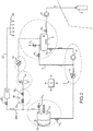
- this machine comprises a storage enclosure 6 (or first storage means), intended to store liquefied gas, at several tens of bars, for example 60 bars.
- This enclosure may be fed with a reserve 2, which has for example the shape of a tank (which contains gas and possibly also liquefied gas at, for example, 20 bar), to which the device can be connected, and by liquefaction means (not shown in the figures) that can be provided at the outlet of this reserve, to form a liquefied gas which is then stored in the chamber 6.
- An autoclave 14, or cleaning chamber accommodates the parts to be cleaned.
- This chamber is provided with a door 15, through which the parts can be introduced into the enclosure, then, after cleaning, extracted from the enclosure. It can also be provided with a vent, or a duct forming a vent, and a valve 14 2 .
- Means for possibly moving this autoclave, as well as means for accommodating baskets that will contain parts to be cleaned, are described in document WO 02/32593 .
- Means 8, comprising, for example, a pump 10 and heating means 12 make it possible to bring the fluid taken from the chamber 6 under thermodynamic conditions that allow it to be used as a cleaning fluid in the cleaning chamber. 14.
- the pump 10 can carry the fluid from the reserve 6 to a higher pressure 73.85 bar, and the heating means 12 can raise the temperature of the fluid to a minimum higher than 31 ° C, these conditions then ensuring the fluid a so-called super-critical state.
- Means 16 make it possible to relax the gas leaving the autoclave 14.
- Means 18 forming a separator make it possible to separate the gas from the impurities which it transports and which result from a previous or ongoing cleaning operation.
- the device here comprises, in addition, second storage means 20 (or storage volume, different from each of the means 6, 18) which will allow to store a portion of the gas that is contained in the autoclave 14 at the end of the cleaning cycle, before opening the door 15 (step e) (or, more generally, before the fluidic communication of the chamber and the external atmosphere), at the pressure P 1 indicated above.
- second storage means 20 or storage volume, different from each of the means 6, 18
- These 2 volumes are connected by a conduit 200.
- the gas is then no longer in the conditions allowing it to be in the dense state, or, for CO 2 , supercritical.
- a set of valves 16 1 , 20 1 will allow to direct, for a predetermined duration, the flow of gas from the autoclave 14 to these storage means 20 via the conduit 200 which connects them.
- These means 20 may further be provided with pressure measuring means.
- means 20 2 for example a valve, make it possible to send part of the gas stored in the means 20, downstream, to the supply means of the enclosure 6.
- these means 20 2 will preferably be closed.
- the means 20 have an internal volume greater than or equal to the internal volume of the autoclave 14.
- This volume is for example of the order of a few tens of liters, for example between 50 l and 100 l.
- the internal volume of the means 20 can be also about 85 l.
- These storage means 20 may be arranged in parallel with means 16 for expanding the gas leaving the autoclave.
- the path followed by the gases leaving the autoclave depends on the actuation of the valves 16 1 , 20 1 : if the valve 16 1 is open, the gas is sent to the means 16 of expansion, and continues its usual route, to the means 18 forming a separator. When this valve 16 1 is open, the valve 20 1 is closed. The opening of the latter is preceded by the closure of the valve 16 1 . Temporarily, the gas is then no longer directed to the expansion means, but to the storage means 20.
- the valve 16 1 is closed and the valve 20 1 is opened. Generally, the valve 16 1 is closed and the valve 20 1 is opened unless the gas from the tank 20 is to be used to pre-fill the volumes 18 and possibly 6.
- the pressure P 2 in the autoclave 14, before opening the valve 14 1 perhaps, for example, substantially identical to that reached in the storage means 20.
- this pressure is substantially lower than the pressure P 1 usually obtained at the end of the cleaning cycle (for example about 60 bar), before opening the door 15.
- P 2 is between on the one hand, P 1 and, on the other hand, P 1/2 .
- first pressure P 1 (respectively P 2 ) to a second pressure P 2 (respectively P 3 ), less than the first, requires no expansion valve, the relaxation being ensured by the distribution of gas from a first volume to an overall volume that is greater than the first volume.
- the total volume constituted by the enclosure 14 and the means 20 is greater, on the one hand, to the single volume of the enclosure 14 and, on the other hand, to the single volume of the means 20; the communication between the two volumes ensures, as a function of the opening time of the valves, the distribution of the gas between them and, at most, the balancing of the pressures between them.
- An initial filling of the means 20 can be carried out at the end of a first cleaning cycle, by opening the valve 20 1 , the gas then being distributed between the two volumes 14, 20, and then closing the same valve. It is then possible to open the valve 14 2 , then the door 15.
- a portion of the gas accumulated in the means 20 can be introduced into the autoclave by opening the valve 20 1 .
- a part of the gas stored in the means 20 thus returns to the chamber 14, in a reverse path from that followed by the gas when it has migrated from the chamber 14 to the means 20.
- This gas therefore passes through the pipe 200 but in the opposite direction.
- the exact amount depends on the degree of opening of the latter and its duration of opening.
- the autoclave is filled with this gas at a pressure of the order of a few bars, for example still between 5 and 15 bar or even 10 bar or even more.
- This step makes it possible, when the dense fluid gas is introduced, under pressure, from the means 8, to prevent it from being under conditions that can lead to the formation of a block of ice (this is the phenomenon in the case of carbon dioxide, formation of dry ice), which is to be avoided because this ice can be very difficult to eliminate quickly.
- a portion of the gas stored in the storage means 20 is used during a previous cleaning cycle, for reinjecting it into the autoclave 14 during or at the beginning of the next cleaning cycle.
- this step is almost instantaneous, by simply opening the valve 20 1 . No pump or pumping step is necessary to introduce the gas, which comes from the autoclave 14, into the storage means and, conversely, to return the gas stored therein to the autoclave 14. at the beginning of the next cleaning cycle.
- the dense fluid can be introduced into the autoclave continuously by the means 20; leaving the autoclave, it can be expanded by the means 16, cleaned by the means 18, liquefied by the means 19 and returned to the means 6 to be reused; this can be repeated or implemented continuously until the end of the treatment. Dense fluid can therefore be recycled continuously.
- Storing means 20 in the part of the gas, provided at the end of cycle in autoclave 14, also reduces the amount of gas that will escape from the latter during the opening of the valve 14 2 (step e). This leads, in particular, to a reduction of the acoustic effect, so practically to a noise reduction, which accompanies the escape of gas from the enclosure.
- all the means which usually implement an additional gas supply can be actuated by gas stored in the means 20.
- the valves are usually implemented with a feed in compressed air.
- the use, for this purpose, of the gas stored in the means 20 eliminates the need for a supply of such additional gas.
- a conduit 23 makes it possible to take gas from the means 20; distribution channels, generally designated by reference 25 on the figure 2 , take this withdrawn gas to, for example, the various pneumatic means of the system, including one or more valves and / or one or more cylinders and / or one or more pumps.
- An expander may be provided at the outlet of the means 20, on the conduit 23, in order to reduce the pressure with a view to these applications.
- the device and method which have been described above are particularly suitable for the implementation of supercritical carbon dioxide cleaning. Nevertheless, this device can also be adapted for operation with another fluid, for example a dense fluid under pressure, or, for example still, with oxygen or nitrogen, under conditions allowing them to be in operation.
- the supercritical state for oxygen: above -119 ° C and 50 bar, for nitrogen: above -147 ° C and 34 bar
- another fluid may be used, for example a fluid among methane, ethanol, propane, nitrous oxide, a fluorinated gas, ammonia, alcohol, ethanol, isopropanol, water.
- an additive such as a solvent can also be introduced into the chamber 14.
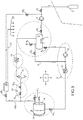
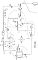
- FIGS. 4A and 4B are variants, respectively machines of figures 2 and 3 described above, wherein the reservoir 20 is fed from a point disposed between the control valve 16 2 and the separator 18.
- the gas migrates from the enclosure 14 to the means 20 via several conduits 200, 201.
- This makes it possible to size the tank for a pressure, for example 60 bar, lower than in the previous embodiments, since it is protected against overpressure by the means 16 1 , 16 2 and the means 18 in the case where, by For example, valve 1 would remain open during operation of a treatment cycle.
- a part of the gas stored in the means 20 returns to the chamber 14, in a reverse path from that followed by the gas when it has migrated from the enclosure 14 to the means 20. This gas therefore passes through the same conduits 200, 201 but in the opposite direction.
- a conduit 210 may connect the output of the enclosure 14 (or a point upstream of the means 16, in the fluid flow direction from the enclosure 14) and the input of the means 20 or the valve 20 1 .
- This duct may be provided with means 211 forming a nonreturn valve, which block a direct flow of the fluid from the chamber 14 to the means 20, but allow flow from the means 20 to the chamber 14.
- a fluid flowing from the enclosure 14 necessarily passes through the means 16; but the opposite is not true, a flow from the means 20 to the chamber 14 can pass through the conduit 210 to join the conduit 200.
- the losses are of the order of 0.2kg per liter of autoclave (value that can vary depending on the temperature).
- Pump 3 completes the internal storage of the lost amount.
- the cycle is the following (we suppose that CO 2 is a perfect gas and we neglect the effect of temperature variations during relaxation).
- the recovery tank 20 is at atmospheric pressure.
- Valve 14 2 was thus opened at 30 bars, instead of 60 bars, ie 2 times less losses.
- the recovery tank 20 is therefore at 30 bars.
- means may be provided for heating or thermostating (or maintaining at constant temperature) the second storage means, so that, or so that the gas stored therein is condensed therein not and / or does not liquefy.
- a device may comprise means 5, of electronic and / or computer type, for controlling and regulating the operation of each of the components of the machine, including pumps and valves, according to a programmed sequence of steps.
- controller means 5 can comprise circuits, which make it possible to send to each of the components of the machine the instructions and / or the voltages making it possible to drive it according to a predefined sequence.
- these means will make it possible to implement a cleaning cycle as described above, and in particular to regulate the gas transfer steps between the autoclave and the discharge storage means. More precisely, these means will control the duration of opening or closing of the valves 1 , 16 1 , 2 , 2 , but also of the other valves of the system, and / or the operating times of the pump 10 and / or compressor 3.
- This assembly 5 may further optionally receive signals corresponding to measurements made with the aid of one or more pressure sensors, for example arranged to measure the pressure in the autoclave 14, or in the storage means 20, and can process and use them to control one or more of the machine components.
- one or more pressure sensors for example arranged to measure the pressure in the autoclave 14, or in the storage means 20, and can process and use them to control one or more of the machine components.
- This controller assembly 5 can communicate with a user interface to inform a user about the state of the machine, in particular its operating cycle.
- these means comprise storage means 53 for storing the instructions relating to data processing, for example to perform a method of the type described above.
- the controller 5 comprises a central unit, which itself comprises a microprocessor 56, a set of non-volatile memories and RAM 57, peripheral circuits, all these elements being coupled to a bus 55.
- Data can stored in the memory areas, including data for implementing a method according to the present invention or for controlling a machine according to the present invention.
- Means 59 will make it possible to manage the flow of input and output data, from the other components of the machine, and towards the latter.
- this controller assembly 5 can be implemented in the form of an FPGA (Field Programmable Gate Array) or an ASIC (Application Specific Integrated Circuit).
- FPGA Field Programmable Gate Array
- ASIC Application Specific Integrated Circuit
- the means 54 which may comprise display means, may optionally allow a user to interact with the operation of a machine according to the invention, for example by intervening on a particular step of an operating cycle.
- a computer program may include instructions for implementing a method according to the invention, in particular as described above.
- a data medium readable by a computer system, may comprise data, in coded form, for implementing a method according to the invention, in particular as described above.
- a software product may comprise a program data support means that can be read by a computer system, making it possible to implement a method according to the invention, in particular as described above.
- a machine according to the invention and a method of operating such a machine, as described above, makes it possible to save components, operating time, and material used.
- CO 2 can be used.
- the fluid used bathes the treated parts.
- the contact, more or less long, between the latter and the fluid causes the desired treatment.
- a debinding process makes it possible to extract a binder from a part made of an alloy, for example from a powder such as a powder assembled in a paraffin, and / or to extract any binder suitable for the manufacture of the alloy.
- a process for extracting one or more natural substances may be used, in particular in the pharmaceutical or agri-food industry.
- a method of extraction, or degreasing can also be used to treat natural wool, in order to extract the ooze.
- this type of treatment is performed by perchlorethylene or water.
- the invention can also be used in processes for impregnating or delivering product carried by the dense or supercritical fluid within the material to be treated.
- the invention also makes it possible to implement a sterilization process (for example in the agri-food or medical field), at low temperature, based on the penetration power of the gas, at high pressure, which will be able to penetrate into the material to be treated. and go neutralize, or kill, infectious agents.
- a sterilization process for example in the agri-food or medical field
- any type of part can be treated by a method according to the invention.
Landscapes
- Chemical & Material Sciences (AREA)
- Organic Chemistry (AREA)
- Chemical Kinetics & Catalysis (AREA)
- Cleaning In General (AREA)
- Cleaning Or Drying Semiconductors (AREA)
- Apparatus For Disinfection Or Sterilisation (AREA)
Claims (15)
- Vorrichtung zum Behandeln mit dichten, unter Druck, Fluiden, umfassend:a) eine Behandlungskammer (14), welche dazu vorgesehen ist, zu behandelnde Stücke aufzunehmen, und welche mit Mitteln (15, 142) versehen ist, um das Innere der Kammer mit einer Umgebungsatmosphäre in Fluidverbindung zu versetzen und dann von ihr zu isolieren,b) Mittel (6, 8) zum Versorgen der Kammer (14) mit dichtem, unter Druck, Fluid, umfassend erste Mittel (6) zum Speichern von Fluid,c) zweite Mittel (20) zum Speichern für ein Speichern in Gasform nach einem Behandlungsschritt und vor einem Versetzen der Kammer in Fluidverbindung mit einer Umgebungsatmosphäre von einem Teil des in der Kammer enthaltenen Gases,d) Mittel (201) zum Versetzen der Behandlungskammer (14) und der zweiten Mittel (20) zum Speichern in Fluidverbindung und zum Erlauben einer Fluidzirkulation von der Behandlungskammer zu den zweiten Mitteln zum Speichern, sowie anschließend von den zweiten Mitteln zum Speichern zu der Behandlungskammer entlang eines umgekehrten Weges,dadurch gekennzeichnet, dass die Vorrichtung umfasst:e) speziell zum Hervorrufen einer Zirkulation eines Fluids von der Behandlungskammer zu den zweiten Mitteln zum Speichern, sowie anschließend von den zweiten Mitteln zum Speichern zu der Behandlungskammer, durch Druckdifferenz zwischen der Behandlungskammer und den zweiten Mitteln zum Speichern programmierte Mittel.
- Vorrichtung nach Anspruch 1, wobei die zweiten Speichermittel (20) parallel zu den Mitteln (16) angeordnet sind, welche ein Ablassen eines Gases an einem Ausgang der Kammer (14) erlauben.
- Vorrichtung nach Anspruch 1, wobei die Mittel (16), welche das Ablassen eines Gases an einem Ausgang der Kammer (14) erlauben, zwischen letzterem und dem Eingang der zweiten Mittel zum Speichern (20) angeordnet sind.
- Vorrichtung nach einem der Ansprüche 1 oder 2, wobei das Verhältnis zwischen dem Innenvolumen der zweiten Mittel zum Speichern (20) und dem Innenvolumen der Kammer (14) wenigstens gleich 1 ist.
- Vorrichtung nach einem der vorhergehenden Ansprüche, ferner umfassend Mittel (202) zum Führen von wenigstens einem Teil des in den Mitteln zum Speichern gespeicherten Fluids zu den Mitteln (3, 6) zum Versorgen der Kammer (14) mit dichtem, unter Druck, Fluid.
- Vorrichtung nach dem vorhergehenden Anspruch, ferner umfassend Mittel (5) zum Führen von wenigstens einem Teil des in den Mitteln zum Speichern gespeicherten Fluids zu den Mitteln (3, 6) zum Versorgen der Kammer (14) mit dichtem Fluid während eines Behandlungszyklus durch die Kammer zum Behandeln.
- Vorrichtung nach einem der vorhergehenden Ansprüche, ferner umfassend Mittel (23, 25) zum Führen von wenigstens einem Teil des in den zweiten Mitteln zum Speichern (20) gespeicherten Fluids zu einem oder mehreren Pneumatik-Steuerelementen.
- Vorrichtung nach dem vorhergehenden Anspruch, wobei das oder die Pneumatikelemente wenigstens ein pneumatisches Ventil und/oder einen pneumatischen Zylinder und/oder eine pneumatische Pumpe umfassen.
- Vorrichtung nach einem der vorhergehenden Ansprüche, ferner umfassend Mittel zum Erhitzen der zweiten Mittel (20) zum Speichern.
- Verfahren zum Behandeln mit dichten, unter Druck, Fluiden, in dieser Reihenfolge:a) Eingeben wenigstens eines ersten zu behandelnden Stücks oder Elements in eine Kammer (14), welche mit Mittel (15, 142) zum Versetzen davon in Fluidverbindung mit einer Außenatmosphäre und einem anschließenden Schließen dieser Mittel (15, 142) versehen ist,b) anschließendes Versorgen der Kammer (14) mit dichtem, unter Druck, Fluid und Behandeln des Stücks,c) anschließendes Speichern in Mitteln (20) zum Speichern in Gasform bei einem Druck P2 kleiner demjenigen (P1), welcher in der Kammer vorliegt, nach dem Schritt b) des Behandelns und vor einem Versetzen des Inneren der Kammer in Fluidverbindung mit der Außenatmosphäre, eines Teils des in der Behandlungskammer enthaltenen Gases,d) Versetzen des Inneren der Kammer in Fluidverbindung mit der Außenatmosphäre,e) Eingeben von wenigstens einem zweiten zu behandelnden Stück in die Kammer (14), anschließend Schließen der Mittel (15, 142) zum Versetzen des Innenraums der Kammer in Fluidverbindung mit der Außenatmosphäre,f) anschließend Eingeben von wenigstens einem Teil des in den Mitteln (20) zum Speichern gespeicherten Gases in die Kammer (14), wobei das in der Kammer (14) enthaltene Gas somit bei einem Druck P3 kleiner als der Druck P2 zum Speichern in den Mitteln (20) zum Speichern vorliegt.
- Verfahren nach Anspruch 10, ferner umfassend eine Injektion von einem Teil des in den Mitteln (20) zum Speichern gespeicherten Gases in Mittel (6) zum hauptsächlichen Speichern, welche stromaufwärts der Mittel (8, 10, 12) angeordnet sind, um ein Fluid in einem dichten, unter Druck Zustand, beispielsweise wenigstens teilweise, während der Behandlung des Stücks zu führen.
- Verfahren nach einem der Ansprüche 10 oder 11, ferner umfassend ein Betätigen von einem oder mehreren Pneumatik-Steuerelementen mit Hilfe eines Teils des in den Mitteln (20) zum Speichern gespeicherten Gases.
- Verfahren nach einem der Ansprüche 10 bis 12, wobei die zweiten Mittel zum Speichern (20) parallel zu Mitteln (16) angeordnet sind, welche ein Ablassen eines Gases an einem Ausgang der Kammer (14) erlauben.
- Verfahren nach einem der Ansprüche 10 bis 13, wobei das zu behandelnde Stück wenigstens teilweise aus einem metallischen Material und/oder einer metallischen Legierung und/oder einem keramischen Material und/oder einem Halbleiter-Material und/oder einem textilen Material und/oder einem natürlichen Material besteht.
- Verfahren nach einem der Ansprüche 10 bis 14, wobei die Behandlung eine Extraktionsbehandlung ist, beispielsweise ein Reinigen oder ein Entfetten oder ein Entbindern oder eine Sterilisation.
Applications Claiming Priority (2)
| Application Number | Priority Date | Filing Date | Title |
|---|---|---|---|
| FR1454886A FR3021552B1 (fr) | 2014-05-28 | 2014-05-28 | Procede et dispositif de traitement par fluide supercritique avec volume de stockage en decharge |
| PCT/EP2015/061889 WO2015181316A1 (fr) | 2014-05-28 | 2015-05-28 | Procédé et dispositif de traitement par fluide super critique avec volume de stockage en décharge |
Publications (2)
| Publication Number | Publication Date |
|---|---|
| EP3148717A1 EP3148717A1 (de) | 2017-04-05 |
| EP3148717B1 true EP3148717B1 (de) | 2018-07-11 |
Family
ID=51518955
Family Applications (1)
| Application Number | Title | Priority Date | Filing Date |
|---|---|---|---|
| EP15726119.9A Not-in-force EP3148717B1 (de) | 2014-05-28 | 2015-05-28 | Behandlungsverfahren und vorrichtung mit einem verdichteten fluid und einem ausstossspeichervolumen |
Country Status (5)
| Country | Link |
|---|---|
| US (1) | US20170182522A1 (de) |
| EP (1) | EP3148717B1 (de) |
| CA (1) | CA2949892A1 (de) |
| FR (1) | FR3021552B1 (de) |
| WO (1) | WO2015181316A1 (de) |
Families Citing this family (2)
| Publication number | Priority date | Publication date | Assignee | Title |
|---|---|---|---|---|
| CN106733945B (zh) * | 2016-12-30 | 2022-11-29 | 上海颐柏热处理设备有限公司 | 一种超临界状态清洗系统及方法 |
| WO2025109757A1 (ja) * | 2023-11-24 | 2025-05-30 | 三菱電機株式会社 | 洗浄装置及び洗浄方法 |
Family Cites Families (3)
| Publication number | Priority date | Publication date | Assignee | Title |
|---|---|---|---|---|
| US6148645A (en) * | 1999-05-14 | 2000-11-21 | Micell Technologies, Inc. | Detergent injection systems for carbon dioxide cleaning apparatus |
| US20040231707A1 (en) * | 2003-05-20 | 2004-11-25 | Paul Schilling | Decontamination of supercritical wafer processing equipment |
| WO2012018349A1 (en) * | 2010-08-06 | 2012-02-09 | Empire Technology Development Llc | Supercritical noble gases and cleaning methods |
-
2014
- 2014-05-28 FR FR1454886A patent/FR3021552B1/fr not_active Expired - Fee Related
-
2015
- 2015-05-28 EP EP15726119.9A patent/EP3148717B1/de not_active Not-in-force
- 2015-05-28 CA CA2949892A patent/CA2949892A1/en not_active Abandoned
- 2015-05-28 US US15/312,819 patent/US20170182522A1/en not_active Abandoned
- 2015-05-28 WO PCT/EP2015/061889 patent/WO2015181316A1/fr not_active Ceased
Non-Patent Citations (1)
| Title |
|---|
| None * |
Also Published As
| Publication number | Publication date |
|---|---|
| US20170182522A1 (en) | 2017-06-29 |
| EP3148717A1 (de) | 2017-04-05 |
| CA2949892A1 (en) | 2015-12-03 |
| FR3021552A1 (fr) | 2015-12-04 |
| FR3021552B1 (fr) | 2018-03-16 |
| WO2015181316A1 (fr) | 2015-12-03 |
Similar Documents
| Publication | Publication Date | Title |
|---|---|---|
| JP5522124B2 (ja) | 基板処理装置、基板処理方法および記憶媒体 | |
| EP3148717B1 (de) | Behandlungsverfahren und vorrichtung mit einem verdichteten fluid und einem ausstossspeichervolumen | |
| WO2016162626A1 (fr) | Station et procédé de remplissage d'un réservoir avec un gaz carburant | |
| FR2919375A1 (fr) | Procede de remplissage d'un gaz sous pression dans un reservoir. | |
| EP2986887B1 (de) | Verfahren und anlage zur versorgung mindestens einer bearbeitungsstation mit einer unterkühlten kryogenen flüssigkeit | |
| EP1922206B1 (de) | Verfahren zum gasblasformen einer verpackung und vorrichtung zu dessen durchführung | |
| CN114263833A (zh) | 一种液态金属润滑轴承灌装装置及方法 | |
| FR3021554A1 (fr) | Procede et dispositif de traitement par fluide supercritique avec injection d'additif | |
| WO2015181317A1 (fr) | Procédé et dispositif de traitement par fluide super critique avec pompage passif | |
| FR3025118A1 (fr) | Dispositif et procede de reparation d'un trou d'une piece | |
| EP0359620B1 (de) | Verfahren und Behälter zum Abliefern vom superkritischen Kohlendioxid | |
| JP4803788B2 (ja) | 炭酸ガスの充填装置 | |
| FR3043922A1 (fr) | Procede et dispositif de traitement par fluide super critique avec pompage passif gravitaire | |
| EP1658386B1 (de) | Verfahren zum gas-abschrecken mit rückgewinnnung des kühlmittels | |
| FR2918292A1 (fr) | Nouveau procede d'extraction par des fluides supercritiques utilisant des cycles compression-decompression appliques a la pression de travail | |
| US11499894B2 (en) | Sample pressure reducing system | |
| EP2236904A1 (de) | Verfahren zur Entladung und Lagerung von flüssigem Erdgas in einem Terminal ohne Gasverdampfung | |
| CN102861989B (zh) | 激光加工机用氮供给装置 | |
| FI4348096T3 (fi) | Järjestely ja menetelmä nestemäisen vetypolttoaineen syöttöjärjestelmässä | |
| JP6082361B2 (ja) | ガス供給方法 | |
| CN112518249A (zh) | 一种薄壁圆辊的加工方法 | |
| EP3071674B1 (de) | Transportgerät für körniges material mit ein geringerer energieverbrauch | |
| WO2012004138A1 (fr) | Appareil integre de liquefaction de dioxyde de carbone et de stockage de dioxyde de carbone liquide et procede de regulation en pression de stockage d'un tel appareil | |
| EP3836785B1 (de) | Kryogene vorrichtung mit einer hydraulischen steuerung | |
| TW202617274A (zh) | 基板處理方法及基板處理裝置 |
Legal Events
| Date | Code | Title | Description |
|---|---|---|---|
| STAA | Information on the status of an ep patent application or granted ep patent |
Free format text: STATUS: THE INTERNATIONAL PUBLICATION HAS BEEN MADE |
|
| PUAI | Public reference made under article 153(3) epc to a published international application that has entered the european phase |
Free format text: ORIGINAL CODE: 0009012 |
|
| STAA | Information on the status of an ep patent application or granted ep patent |
Free format text: STATUS: REQUEST FOR EXAMINATION WAS MADE |
|
| 17P | Request for examination filed |
Effective date: 20161201 |
|
| AK | Designated contracting states |
Kind code of ref document: A1 Designated state(s): AL AT BE BG CH CY CZ DE DK EE ES FI FR GB GR HR HU IE IS IT LI LT LU LV MC MK MT NL NO PL PT RO RS SE SI SK SM TR |
|
| AX | Request for extension of the european patent |
Extension state: BA ME |
|
| DAV | Request for validation of the european patent (deleted) | ||
| DAX | Request for extension of the european patent (deleted) | ||
| GRAP | Despatch of communication of intention to grant a patent |
Free format text: ORIGINAL CODE: EPIDOSNIGR1 |
|
| STAA | Information on the status of an ep patent application or granted ep patent |
Free format text: STATUS: GRANT OF PATENT IS INTENDED |
|
| INTG | Intention to grant announced |
Effective date: 20171129 |
|
| GRAS | Grant fee paid |
Free format text: ORIGINAL CODE: EPIDOSNIGR3 |
|
| GRAJ | Information related to disapproval of communication of intention to grant by the applicant or resumption of examination proceedings by the epo deleted |
Free format text: ORIGINAL CODE: EPIDOSDIGR1 |
|
| GRAL | Information related to payment of fee for publishing/printing deleted |
Free format text: ORIGINAL CODE: EPIDOSDIGR3 |
|
| STAA | Information on the status of an ep patent application or granted ep patent |
Free format text: STATUS: REQUEST FOR EXAMINATION WAS MADE |
|
| GRAR | Information related to intention to grant a patent recorded |
Free format text: ORIGINAL CODE: EPIDOSNIGR71 |
|
| STAA | Information on the status of an ep patent application or granted ep patent |
Free format text: STATUS: GRANT OF PATENT IS INTENDED |
|
| GRAA | (expected) grant |
Free format text: ORIGINAL CODE: 0009210 |
|
| STAA | Information on the status of an ep patent application or granted ep patent |
Free format text: STATUS: THE PATENT HAS BEEN GRANTED |
|
| INTG | Intention to grant announced |
Effective date: 20180530 |
|
| AK | Designated contracting states |
Kind code of ref document: B1 Designated state(s): AL AT BE BG CH CY CZ DE DK EE ES FI FR GB GR HR HU IE IS IT LI LT LU LV MC MK MT NL NO PL PT RO RS SE SI SK SM TR |
|
| REG | Reference to a national code |
Ref country code: GB Ref legal event code: FG4D Free format text: NOT ENGLISH |
|
| REG | Reference to a national code |
Ref country code: CH Ref legal event code: EP |
|
| REG | Reference to a national code |
Ref country code: AT Ref legal event code: REF Ref document number: 1016351 Country of ref document: AT Kind code of ref document: T Effective date: 20180715 |
|
| REG | Reference to a national code |
Ref country code: IE Ref legal event code: FG4D Free format text: LANGUAGE OF EP DOCUMENT: FRENCH |
|
| REG | Reference to a national code |
Ref country code: DE Ref legal event code: R096 Ref document number: 602015013437 Country of ref document: DE |
|
| REG | Reference to a national code |
Ref country code: NL Ref legal event code: MP Effective date: 20180711 |
|
| REG | Reference to a national code |
Ref country code: LT Ref legal event code: MG4D |
|
| REG | Reference to a national code |
Ref country code: AT Ref legal event code: MK05 Ref document number: 1016351 Country of ref document: AT Kind code of ref document: T Effective date: 20180711 |
|
| PG25 | Lapsed in a contracting state [announced via postgrant information from national office to epo] |
Ref country code: NL Free format text: LAPSE BECAUSE OF FAILURE TO SUBMIT A TRANSLATION OF THE DESCRIPTION OR TO PAY THE FEE WITHIN THE PRESCRIBED TIME-LIMIT Effective date: 20180711 |
|
| PG25 | Lapsed in a contracting state [announced via postgrant information from national office to epo] |
Ref country code: GR Free format text: LAPSE BECAUSE OF FAILURE TO SUBMIT A TRANSLATION OF THE DESCRIPTION OR TO PAY THE FEE WITHIN THE PRESCRIBED TIME-LIMIT Effective date: 20181012 Ref country code: NO Free format text: LAPSE BECAUSE OF FAILURE TO SUBMIT A TRANSLATION OF THE DESCRIPTION OR TO PAY THE FEE WITHIN THE PRESCRIBED TIME-LIMIT Effective date: 20181011 Ref country code: SE Free format text: LAPSE BECAUSE OF FAILURE TO SUBMIT A TRANSLATION OF THE DESCRIPTION OR TO PAY THE FEE WITHIN THE PRESCRIBED TIME-LIMIT Effective date: 20180711 Ref country code: AT Free format text: LAPSE BECAUSE OF FAILURE TO SUBMIT A TRANSLATION OF THE DESCRIPTION OR TO PAY THE FEE WITHIN THE PRESCRIBED TIME-LIMIT Effective date: 20180711 Ref country code: IS Free format text: LAPSE BECAUSE OF FAILURE TO SUBMIT A TRANSLATION OF THE DESCRIPTION OR TO PAY THE FEE WITHIN THE PRESCRIBED TIME-LIMIT Effective date: 20181111 Ref country code: RS Free format text: LAPSE BECAUSE OF FAILURE TO SUBMIT A TRANSLATION OF THE DESCRIPTION OR TO PAY THE FEE WITHIN THE PRESCRIBED TIME-LIMIT Effective date: 20180711 Ref country code: FI Free format text: LAPSE BECAUSE OF FAILURE TO SUBMIT A TRANSLATION OF THE DESCRIPTION OR TO PAY THE FEE WITHIN THE PRESCRIBED TIME-LIMIT Effective date: 20180711 Ref country code: PL Free format text: LAPSE BECAUSE OF FAILURE TO SUBMIT A TRANSLATION OF THE DESCRIPTION OR TO PAY THE FEE WITHIN THE PRESCRIBED TIME-LIMIT Effective date: 20180711 Ref country code: BG Free format text: LAPSE BECAUSE OF FAILURE TO SUBMIT A TRANSLATION OF THE DESCRIPTION OR TO PAY THE FEE WITHIN THE PRESCRIBED TIME-LIMIT Effective date: 20181011 Ref country code: LT Free format text: LAPSE BECAUSE OF FAILURE TO SUBMIT A TRANSLATION OF THE DESCRIPTION OR TO PAY THE FEE WITHIN THE PRESCRIBED TIME-LIMIT Effective date: 20180711 |
|
| PG25 | Lapsed in a contracting state [announced via postgrant information from national office to epo] |
Ref country code: AL Free format text: LAPSE BECAUSE OF FAILURE TO SUBMIT A TRANSLATION OF THE DESCRIPTION OR TO PAY THE FEE WITHIN THE PRESCRIBED TIME-LIMIT Effective date: 20180711 Ref country code: HR Free format text: LAPSE BECAUSE OF FAILURE TO SUBMIT A TRANSLATION OF THE DESCRIPTION OR TO PAY THE FEE WITHIN THE PRESCRIBED TIME-LIMIT Effective date: 20180711 Ref country code: LV Free format text: LAPSE BECAUSE OF FAILURE TO SUBMIT A TRANSLATION OF THE DESCRIPTION OR TO PAY THE FEE WITHIN THE PRESCRIBED TIME-LIMIT Effective date: 20180711 |
|
| REG | Reference to a national code |
Ref country code: DE Ref legal event code: R097 Ref document number: 602015013437 Country of ref document: DE |
|
| PG25 | Lapsed in a contracting state [announced via postgrant information from national office to epo] |
Ref country code: EE Free format text: LAPSE BECAUSE OF FAILURE TO SUBMIT A TRANSLATION OF THE DESCRIPTION OR TO PAY THE FEE WITHIN THE PRESCRIBED TIME-LIMIT Effective date: 20180711 Ref country code: RO Free format text: LAPSE BECAUSE OF FAILURE TO SUBMIT A TRANSLATION OF THE DESCRIPTION OR TO PAY THE FEE WITHIN THE PRESCRIBED TIME-LIMIT Effective date: 20180711 Ref country code: CZ Free format text: LAPSE BECAUSE OF FAILURE TO SUBMIT A TRANSLATION OF THE DESCRIPTION OR TO PAY THE FEE WITHIN THE PRESCRIBED TIME-LIMIT Effective date: 20180711 Ref country code: ES Free format text: LAPSE BECAUSE OF FAILURE TO SUBMIT A TRANSLATION OF THE DESCRIPTION OR TO PAY THE FEE WITHIN THE PRESCRIBED TIME-LIMIT Effective date: 20180711 Ref country code: IT Free format text: LAPSE BECAUSE OF FAILURE TO SUBMIT A TRANSLATION OF THE DESCRIPTION OR TO PAY THE FEE WITHIN THE PRESCRIBED TIME-LIMIT Effective date: 20180711 |
|
| PLBE | No opposition filed within time limit |
Free format text: ORIGINAL CODE: 0009261 |
|
| STAA | Information on the status of an ep patent application or granted ep patent |
Free format text: STATUS: NO OPPOSITION FILED WITHIN TIME LIMIT |
|
| PG25 | Lapsed in a contracting state [announced via postgrant information from national office to epo] |
Ref country code: SK Free format text: LAPSE BECAUSE OF FAILURE TO SUBMIT A TRANSLATION OF THE DESCRIPTION OR TO PAY THE FEE WITHIN THE PRESCRIBED TIME-LIMIT Effective date: 20180711 Ref country code: SM Free format text: LAPSE BECAUSE OF FAILURE TO SUBMIT A TRANSLATION OF THE DESCRIPTION OR TO PAY THE FEE WITHIN THE PRESCRIBED TIME-LIMIT Effective date: 20180711 Ref country code: DK Free format text: LAPSE BECAUSE OF FAILURE TO SUBMIT A TRANSLATION OF THE DESCRIPTION OR TO PAY THE FEE WITHIN THE PRESCRIBED TIME-LIMIT Effective date: 20180711 |
|
| 26N | No opposition filed |
Effective date: 20190412 |
|
| PG25 | Lapsed in a contracting state [announced via postgrant information from national office to epo] |
Ref country code: SI Free format text: LAPSE BECAUSE OF FAILURE TO SUBMIT A TRANSLATION OF THE DESCRIPTION OR TO PAY THE FEE WITHIN THE PRESCRIBED TIME-LIMIT Effective date: 20180711 |
|
| REG | Reference to a national code |
Ref country code: DE Ref legal event code: R119 Ref document number: 602015013437 Country of ref document: DE |
|
| REG | Reference to a national code |
Ref country code: CH Ref legal event code: PL |
|
| GBPC | Gb: european patent ceased through non-payment of renewal fee |
Effective date: 20190528 |
|
| PG25 | Lapsed in a contracting state [announced via postgrant information from national office to epo] |
Ref country code: MC Free format text: LAPSE BECAUSE OF FAILURE TO SUBMIT A TRANSLATION OF THE DESCRIPTION OR TO PAY THE FEE WITHIN THE PRESCRIBED TIME-LIMIT Effective date: 20180711 Ref country code: LI Free format text: LAPSE BECAUSE OF NON-PAYMENT OF DUE FEES Effective date: 20190531 Ref country code: CH Free format text: LAPSE BECAUSE OF NON-PAYMENT OF DUE FEES Effective date: 20190531 |
|
| REG | Reference to a national code |
Ref country code: BE Ref legal event code: MM Effective date: 20190531 |
|
| PG25 | Lapsed in a contracting state [announced via postgrant information from national office to epo] |
Ref country code: LU Free format text: LAPSE BECAUSE OF NON-PAYMENT OF DUE FEES Effective date: 20190528 |
|
| PG25 | Lapsed in a contracting state [announced via postgrant information from national office to epo] |
Ref country code: TR Free format text: LAPSE BECAUSE OF FAILURE TO SUBMIT A TRANSLATION OF THE DESCRIPTION OR TO PAY THE FEE WITHIN THE PRESCRIBED TIME-LIMIT Effective date: 20180711 |
|
| PG25 | Lapsed in a contracting state [announced via postgrant information from national office to epo] |
Ref country code: IE Free format text: LAPSE BECAUSE OF NON-PAYMENT OF DUE FEES Effective date: 20190528 Ref country code: DE Free format text: LAPSE BECAUSE OF NON-PAYMENT OF DUE FEES Effective date: 20191203 Ref country code: GB Free format text: LAPSE BECAUSE OF NON-PAYMENT OF DUE FEES Effective date: 20190528 |
|
| PG25 | Lapsed in a contracting state [announced via postgrant information from national office to epo] |
Ref country code: BE Free format text: LAPSE BECAUSE OF NON-PAYMENT OF DUE FEES Effective date: 20190531 |
|
| PG25 | Lapsed in a contracting state [announced via postgrant information from national office to epo] |
Ref country code: PT Free format text: LAPSE BECAUSE OF FAILURE TO SUBMIT A TRANSLATION OF THE DESCRIPTION OR TO PAY THE FEE WITHIN THE PRESCRIBED TIME-LIMIT Effective date: 20181111 Ref country code: FR Free format text: LAPSE BECAUSE OF NON-PAYMENT OF DUE FEES Effective date: 20190531 |
|
| PG25 | Lapsed in a contracting state [announced via postgrant information from national office to epo] |
Ref country code: CY Free format text: LAPSE BECAUSE OF FAILURE TO SUBMIT A TRANSLATION OF THE DESCRIPTION OR TO PAY THE FEE WITHIN THE PRESCRIBED TIME-LIMIT Effective date: 20180711 |
|
| PG25 | Lapsed in a contracting state [announced via postgrant information from national office to epo] |
Ref country code: MT Free format text: LAPSE BECAUSE OF FAILURE TO SUBMIT A TRANSLATION OF THE DESCRIPTION OR TO PAY THE FEE WITHIN THE PRESCRIBED TIME-LIMIT Effective date: 20180711 Ref country code: HU Free format text: LAPSE BECAUSE OF FAILURE TO SUBMIT A TRANSLATION OF THE DESCRIPTION OR TO PAY THE FEE WITHIN THE PRESCRIBED TIME-LIMIT; INVALID AB INITIO Effective date: 20150528 |
|
| PG25 | Lapsed in a contracting state [announced via postgrant information from national office to epo] |
Ref country code: MK Free format text: LAPSE BECAUSE OF FAILURE TO SUBMIT A TRANSLATION OF THE DESCRIPTION OR TO PAY THE FEE WITHIN THE PRESCRIBED TIME-LIMIT Effective date: 20180711 |