EP3148719B1 - Verfahren zur hydrothermalen karbonisierung von biomasse und zugehörige vorrichtung - Google Patents
Verfahren zur hydrothermalen karbonisierung von biomasse und zugehörige vorrichtung Download PDFInfo
- Publication number
- EP3148719B1 EP3148719B1 EP15798220.8A EP15798220A EP3148719B1 EP 3148719 B1 EP3148719 B1 EP 3148719B1 EP 15798220 A EP15798220 A EP 15798220A EP 3148719 B1 EP3148719 B1 EP 3148719B1
- Authority
- EP
- European Patent Office
- Prior art keywords
- biomass
- treatment station
- heat
- steam
- heating means
- Prior art date
- Legal status (The legal status is an assumption and is not a legal conclusion. Google has not performed a legal analysis and makes no representation as to the accuracy of the status listed.)
- Active
Links
Images

Classifications
-
- C—CHEMISTRY; METALLURGY
- C01—INORGANIC CHEMISTRY
- C01B—NON-METALLIC ELEMENTS; COMPOUNDS THEREOF; METALLOIDS OR COMPOUNDS THEREOF NOT COVERED BY SUBCLASS C01C
- C01B32/00—Carbon; Compounds thereof
- C01B32/05—Preparation or purification of carbon not covered by groups C01B32/15, C01B32/20, C01B32/25, C01B32/30
-
- C—CHEMISTRY; METALLURGY
- C02—TREATMENT OF WATER, WASTE WATER, SEWAGE, OR SLUDGE
- C02F—TREATMENT OF WATER, WASTE WATER, SEWAGE, OR SLUDGE
- C02F1/00—Treatment of water, waste water, or sewage
- C02F1/008—Control or steering systems not provided for elsewhere in subclass C02F
-
- C—CHEMISTRY; METALLURGY
- C02—TREATMENT OF WATER, WASTE WATER, SEWAGE, OR SLUDGE
- C02F—TREATMENT OF WATER, WASTE WATER, SEWAGE, OR SLUDGE
- C02F11/00—Treatment of sludge; Devices therefor
- C02F11/10—Treatment of sludge; Devices therefor by pyrolysis
-
- F—MECHANICAL ENGINEERING; LIGHTING; HEATING; WEAPONS; BLASTING
- F23—COMBUSTION APPARATUS; COMBUSTION PROCESSES
- F23G—CREMATION FURNACES; CONSUMING WASTE PRODUCTS BY COMBUSTION
- F23G5/00—Incineration of waste; Incinerator constructions; Details, accessories or control therefor
- F23G5/02—Incineration of waste; Incinerator constructions; Details, accessories or control therefor with pretreatment
- F23G5/027—Incineration of waste; Incinerator constructions; Details, accessories or control therefor with pretreatment pyrolising or gasifying stage
- F23G5/0273—Incineration of waste; Incinerator constructions; Details, accessories or control therefor with pretreatment pyrolising or gasifying stage using indirect heating
-
- C—CHEMISTRY; METALLURGY
- C02—TREATMENT OF WATER, WASTE WATER, SEWAGE, OR SLUDGE
- C02F—TREATMENT OF WATER, WASTE WATER, SEWAGE, OR SLUDGE
- C02F2103/00—Nature of the water, waste water, sewage or sludge to be treated
- C02F2103/005—Black water originating from toilets
-
- C—CHEMISTRY; METALLURGY
- C02—TREATMENT OF WATER, WASTE WATER, SEWAGE, OR SLUDGE
- C02F—TREATMENT OF WATER, WASTE WATER, SEWAGE, OR SLUDGE
- C02F2209/00—Controlling or monitoring parameters in water treatment
- C02F2209/02—Temperature
-
- C—CHEMISTRY; METALLURGY
- C02—TREATMENT OF WATER, WASTE WATER, SEWAGE, OR SLUDGE
- C02F—TREATMENT OF WATER, WASTE WATER, SEWAGE, OR SLUDGE
- C02F2209/00—Controlling or monitoring parameters in water treatment
- C02F2209/03—Pressure
-
- C—CHEMISTRY; METALLURGY
- C02—TREATMENT OF WATER, WASTE WATER, SEWAGE, OR SLUDGE
- C02F—TREATMENT OF WATER, WASTE WATER, SEWAGE, OR SLUDGE
- C02F2301/00—General aspects of water treatment
- C02F2301/06—Pressure conditions
- C02F2301/066—Overpressure, high pressure
-
- C—CHEMISTRY; METALLURGY
- C02—TREATMENT OF WATER, WASTE WATER, SEWAGE, OR SLUDGE
- C02F—TREATMENT OF WATER, WASTE WATER, SEWAGE, OR SLUDGE
- C02F2303/00—Specific treatment goals
- C02F2303/10—Energy recovery
-
- C—CHEMISTRY; METALLURGY
- C02—TREATMENT OF WATER, WASTE WATER, SEWAGE, OR SLUDGE
- C02F—TREATMENT OF WATER, WASTE WATER, SEWAGE, OR SLUDGE
- C02F2303/00—Specific treatment goals
- C02F2303/22—Eliminating or preventing deposits, scale removal, scale prevention
-
- F—MECHANICAL ENGINEERING; LIGHTING; HEATING; WEAPONS; BLASTING
- F23—COMBUSTION APPARATUS; COMBUSTION PROCESSES
- F23G—CREMATION FURNACES; CONSUMING WASTE PRODUCTS BY COMBUSTION
- F23G2202/00—Combustion
- F23G2202/30—Combustion in a pressurised chamber
-
- F—MECHANICAL ENGINEERING; LIGHTING; HEATING; WEAPONS; BLASTING
- F23—COMBUSTION APPARATUS; COMBUSTION PROCESSES
- F23G—CREMATION FURNACES; CONSUMING WASTE PRODUCTS BY COMBUSTION
- F23G2209/00—Specific waste
- F23G2209/12—Sludge, slurries or mixtures of liquids
-
- Y—GENERAL TAGGING OF NEW TECHNOLOGICAL DEVELOPMENTS; GENERAL TAGGING OF CROSS-SECTIONAL TECHNOLOGIES SPANNING OVER SEVERAL SECTIONS OF THE IPC; TECHNICAL SUBJECTS COVERED BY FORMER USPC CROSS-REFERENCE ART COLLECTIONS [XRACs] AND DIGESTS
- Y02—TECHNOLOGIES OR APPLICATIONS FOR MITIGATION OR ADAPTATION AGAINST CLIMATE CHANGE
- Y02E—REDUCTION OF GREENHOUSE GAS [GHG] EMISSIONS, RELATED TO ENERGY GENERATION, TRANSMISSION OR DISTRIBUTION
- Y02E50/00—Technologies for the production of fuel of non-fossil origin
- Y02E50/10—Biofuels, e.g. bio-diesel
-
- Y—GENERAL TAGGING OF NEW TECHNOLOGICAL DEVELOPMENTS; GENERAL TAGGING OF CROSS-SECTIONAL TECHNOLOGIES SPANNING OVER SEVERAL SECTIONS OF THE IPC; TECHNICAL SUBJECTS COVERED BY FORMER USPC CROSS-REFERENCE ART COLLECTIONS [XRACs] AND DIGESTS
- Y02—TECHNOLOGIES OR APPLICATIONS FOR MITIGATION OR ADAPTATION AGAINST CLIMATE CHANGE
- Y02W—CLIMATE CHANGE MITIGATION TECHNOLOGIES RELATED TO WASTEWATER TREATMENT OR WASTE MANAGEMENT
- Y02W10/00—Technologies for wastewater treatment
- Y02W10/30—Wastewater or sewage treatment systems using renewable energies
-
- Y—GENERAL TAGGING OF NEW TECHNOLOGICAL DEVELOPMENTS; GENERAL TAGGING OF CROSS-SECTIONAL TECHNOLOGIES SPANNING OVER SEVERAL SECTIONS OF THE IPC; TECHNICAL SUBJECTS COVERED BY FORMER USPC CROSS-REFERENCE ART COLLECTIONS [XRACs] AND DIGESTS
- Y02—TECHNOLOGIES OR APPLICATIONS FOR MITIGATION OR ADAPTATION AGAINST CLIMATE CHANGE
- Y02W—CLIMATE CHANGE MITIGATION TECHNOLOGIES RELATED TO WASTEWATER TREATMENT OR WASTE MANAGEMENT
- Y02W10/00—Technologies for wastewater treatment
- Y02W10/40—Valorisation of by-products of wastewater, sewage or sludge processing
Definitions
- the present invention relates to the field of thermal and chemical treatment of a biomass such as sludge from a wastewater treatment sector.
- the present invention more particularly relates to a method of hydrothermal carbonization of a biomass and a device for implementing such a method.
- a hydrothermal carbonization process typically involves subjecting a biomass to a temperature close to 200 ° C. (for example US2006 / 096163 ) and at a pressure close to 20 bar.
- the patent EP 2 388 305 A2 describes an installation comprising a treatment path in which a biomass is circulated, this path including in particular a heat exchanger and a reactor.
- the heat exchanger is arranged to heat the biomass circulating in the path through a transfer circuit in which circulates a transfer fluid. After having been preheated in this heat exchanger, the biomass is then carbonized in the reactor in which it performs an average residence time of about 4 hours.
- the present invention is intended in particular to overcome all or part of these disadvantages by proposing a method for heating a biomass, as well as a device for implementing such a method, optimizing the heat exchange and exploiting the thermal energy produced by the implementation of such a method or the operation of such a device.
- the present invention provides a method for heating a moving biomass in an industrial process path having an inlet for the incoming biomass, a pressurizing pump, a heating means and a treatment station, characterized in that that steam is injected into the path between the pressurizing pump and the heating means and that it comprises a step of injecting an additive into the biomass upstream of the heating means in which one injects the additive into the biomass so that the additive is subjected to the injected vapor.
- This injection makes it possible to preheat the biomass by condensation of the vapor.
- the steam can be injected at a pressure at least 0.2 MPa higher than the pressure of the biomass (biomass pressure at the steam injection).
- the injection speed of the steam may be greater than 130 m / s, for example between 200 and 250 m / s.
- the rate of vapor injection is typically generated by the differential pressure of biomass and vapor injection pressure.
- the vapor velocity previously mentioned preferably corresponds to a velocity of the vapor just before the vapor comes into contact with the biomass.
- the steam injection rate can correspond to up to 20% of the flow rate of the biomass moving in the path.
- Such a method makes it possible to reduce the viscosity of the biomass upstream of the heating means compared with a method that does not produce such a steam injection. This results in a reduction in the pressure drop in the path and an improvement in the heat exchange gain at the heating means. This results in a greater increase in temperature of the biomass.
- the biomass is a sewage sludge, preferably dehydrated, and the treatment is a hydrothermal carbonization.
- sewage sludge especially dehydrated, has relatively poor heat exchange coefficients, that is to say, disadvantaging its rise in temperature and involving very large equipment sizes.
- the method according to the invention makes it possible to improve the exchange coefficients of such a sludge.
- Said equipment sizes may in particular be exchanger sizes.
- the steam injection is controlled, for example by controlling the flow rate of injected vapor, and the heating means for the temperature of the biomass to reach a parameterized temperature before reaching the treatment station. set temperature being between 165 ° C and 205 ° C, preferably 185 ° C.
- the temperature of the biomass upon arrival at the treatment station is sufficiently high, particularly when the treatment is a hydrothermal carbonization, to avoid having to further increase the temperature of the biomass within the treatment station .
- This eliminates the heating function of the treatment station, and thus eliminate the temperature gradient in the treatment station resulting from such a function. Consequently, a process provided with such a characteristic makes it possible to limit the bonding by baking (or depositing) of the biomass on the walls of the treatment station, such a bonding or deposit which can lead to an interruption of the heat exchange in the station of treatment. It also makes it possible to dispense with any means or operation intended to limit such gluing or deposition (for example, a scraping and / or mixing operation).
- Another advantage of the elimination of the heating function of the treatment station is that, for a given quantity of biomass to be treated, the volume of the treatment station can be reduced, because the residence time of the biomass, in the station of treatment, associated with the heating function is no longer necessary.
- the steam is injected obliquely or preferably perpendicularly to the direction of movement of the biomass in the path.
- This direction of movement of the biomass in the path is the direction in which the biomass moves in an injection zone of the steam in the path.
- An oblique or preferably perpendicular injection creates a shear of the biomass favoring the dilution of the vapor in the biomass and thus promoting its increase in temperature by condensation of the vapor.
- the injected vapor is mixed with the biomass by guiding this vapor and this biomass through a static mixer, for example taking the form baffles, an Archimedean screw or fixed guide surfaces suitable for generate turbulence of the biomass and the vapor circulating in such a mixer.
- a static mixer for example taking the form baffles, an Archimedean screw or fixed guide surfaces suitable for generate turbulence of the biomass and the vapor circulating in such a mixer.
- baffles, or such an Archimedes screw or such fixed guide surfaces are able to increase the turbulence of the biomass and the steam flowing in such a mixer.
- such a mixture of the steam and the biomass through the static mixer is produced after prior dynamic mixing of the vapor and the biomass, ie after the steam injection zone in the path, in this case in the mixer.
- the steam can be injected into a configuration of the ejector type piping allowing, in addition to mixing, an improvement in the pressurization of the biomass.
- the steam injection is piloted to bring the temperature of the biomass to a value of greater than 70 ° C. at the inlet of the heating means.
- the steam flow is controlled.
- the pressurizing pump raises the pressure of the biomass to a value making it possible to heat the biomass to a temperature greater than 100 ° C. without boiling.
- the pressurizing pump can raise the pressure of the biomass above the saturation pressure, typically above 1.2 MPa.
- the pressure at the outlet of the pressurizing pump is greater than 3 MPa.
- the path further includes a cooling station downstream of the treatment station, and a transfer fluid is heated in its path between the cooling station and the heating means.
- the transfer fluid is heated to a temperature higher than that of the biomass at the treatment station.
- the heat transferred to the heating means can thus heat the biomass to said parameterized temperature before arriving at the treatment station.
- the transfer fluid can be heated to a temperature above 220 ° C.
- the external heat source may consist of a boiler burner.
- heat is recovered from the biomass downstream of the treatment station and this recovered heat is transferred to the biomass upstream of the treatment station.
- the method comprises a step of injecting an additive into the biomass upstream of the heating means.
- the injected additive may consist of any catalyst capable of decomposing the organic material, for example an acid such as sulfuric acid or a catalyst as described in the patent EP 2 388 305 A2 .
- Such an injection step also contributes to lowering the viscosity of the biomass and thus promoting its rise in temperature, and also reduces the fouling phenomena in the path.
- the injection step can be performed downstream or within the heating means.
- the additive is injected into the biomass so that the additive is subjected to the injected vapor.
- the additive is injected into the biomass so that the additive, during its injection, is subjected to a stream of vapor generated by the steam injection.
- the additive is mixed with the biomass under the action of the steam which creates an area of turbulence. More precisely, the additive is thus intimately mixed with the biomass shredded into particles under the action of the steam which creates an area of turbulence.
- the additive and the steam in the biomass can be injected into an interior volume of a receptacle, this receptacle being for example a receptacle or a pipe or a pipe element.
- a part of the biomass is taken from the treatment station by means of a recirculation branch and this part is returned to the treatment station so as to generate a movement of the biomass in the treatment station. the treatment station.
- Such removal and return of biomass part in the treatment station limits the sticking or deposition of biomass in the treatment station, and to overcome any means or operation to limit such bonding or deposit.
- the portion of biomass is sampled at a flow rate of between 5 and 15 times the flow of biomass entering the treatment station.
- the injected vapor and the biomass can be mixed in the path between the pressurizing pump and the heating means with a mixer.
- the water vapor generating means and the mixer may be arranged to inject the steam into the mixer at a pressure at least 0.2 MPa higher than the biomass pressure at the injection level. steam.
- the steam generating means and the mixer may be arranged to inject the steam into the mixer with a steam injection rate greater than 130 m / s, for example between 200 and 250 m / s.
- the rate of vapor injection is typically generated by the pressure differential of the biomass and steam injection pressure and / or by the respective dimensions of the biomass and steam injection members.
- the device may be arranged to inject steam into the mixer with a steam injection rate corresponding to 20% or less of the flow rate of the biomass moving in the path.
- the steam generating means and the mixer may be arranged to inject the vapor obliquely or preferably perpendicular to the direction of movement of the biomass in the path.
- This direction of movement of the biomass in the path is the direction in which the biomass moves in an injection zone of the steam in the path.
- the water vapor generating means and the mixer may also be arranged to inject steam against the current of the biomass.
- the water vapor generation means and the mixer may be arranged to inject the vapor co-current biomass.
- the device further comprises injection means capable of injecting an additive into the path, so that the additive is subjected to the injected vapor.
- the mixer may comprise a receptacle such as a container or pipe or piping element.
- the vapor velocity previously mentioned preferably corresponds to a velocity of the vapor just before the vapor comes into contact with the biomass, ie in the zone of injection of the vapor in the path, this zone being located in the interior volume of the receptacle.
- the mixer may be or comprise a static mixer, preferably within a receptacle as previously mentioned.
- the device can be arranged to heat the transfer fluid to a temperature above 220 ° C.
- the pressurizing pump may be arranged to raise the pressure of the biomass above the saturation pressure, typically greater than 1.2 MPa.
- the device further comprises an external heat source arranged to heat the transfer fluid and a coolant circulating in an envelope of the station. treatment, preferably so as to ensure a rise and / or maintenance of temperature of the biomass at the treatment station.
- the transfer fluid and the coolant are identical.
- the device is arranged so that the biomass enters the treatment station by a lower part and so by an upper part.
- a biomass especially when it consists of sewage sludge, is denser than the surrounding water.
- the solid fraction, surrounded by undissolved organic matter, will therefore tend to have a gravitational effect at a lower altitude compared to the already solubilized fractions and therefore for which the carbonization reactions are in progress or have already taken place.
- the residence time of a fraction of non-carbonized biomass in the treatment station is thus increased, compared to a device that enters the biomass through an upper part and makes it exit through a lower part.
- the relative increase in residence time of the biomass in the treatment station increases the quality of the treatment.
- the device according to the invention further comprises a recirculation branch arranged to withdraw a portion of biomass in the treatment station and to return this portion of biomass in the treatment station.
- the treatment station is mechanically passive, that is to say having no scraper or mixer.
- the treatment station is a hydrothermal carbonization reactor for sewage sludge.
- variants of the invention comprising only a selection of characteristics described, isolated from the other characteristics described (even if this selection is isolated within a sentence including these other characteristics), if this selection of features is sufficient to confer a technical advantage or to differentiate the invention from the state of the prior art.
- This selection comprises at least one characteristic, preferably functional without structural details, or with only a part of the structural details if this part alone is sufficient to confer a technical advantage or to differentiate the invention from the state of the prior art .
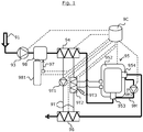
- the FIGURE 1 illustrates a preferred embodiment of the invention.
- the device according to the invention comprises an industrial treatment path in which biomass circulates.
- Incoming biomass for example dehydrated sewage sludge, enters through an inlet 91 in the path where it is introduced into a pipework connecting the inlet 91 to a mixer 98, this piping comprising between the inlet 91 and the mixer 98 a pressurizing pump 93.
- the pressurizing pump 93 raises the pressure of the biomass to a value for heating the biomass to a temperature above 100 ° C without boiling. In other words, the pressurizing pump 93 raises the pressure of the biomass above the saturation pressure, typically greater than 1.2 MPa.
- the pressurizing pump 93 makes it possible to circulate the biomass in the path.
- the pressurizing pump 93 is of a type capable of raising the pressure of the biomass at the pump outlet 93 to a value greater than 3 MPa (piston pump, diaphragm pump or other).
- the biomass is conveyed from the pressurizing pump 93 to the mixer 98.
- the mixer 98 is arranged to mix steam produced by a steam generation means 981 with the biomass.
- Mixer 98 can be a static mixer (means that requires biomass and water vapor to travel together for a sufficient time to promote mixing between steam and biomass) or consist of a mixer capable of receiving steam perpendicular to the direction of movement of the biomass in the piping connecting the pressurizing pump 93 and the heating means 94, or consist of a configuration of the ejector type piping.
- the steam flow is preferably controlled, for example by the control means 9C, so as to raise the temperature of the biomass (mixed with an additive) to an optimum operating point both for the dimensioning of the various elements of the device, by example the heating means 94, only for the overall energy consumption of the device.
- the steam flow rate is preferably controlled by controlling the flow rate of the injected vapor.
- the steam is injected with a pressure greater than that of the biomass in the path upstream of the pressurizing pump 93, and therefore at a temperature above the temperature of the biomass.
- the steam generation means 981 is piloted to raise the temperature of the biomass so as to optimize the energy recovery implemented in the device.
- the steam injection rate can correspond to up to 20% of the flow rate of the biomass moving in the path.
- An additive is injected into the biomass by any appropriate injection means 97, preferably upstream of the heating means 94, in order to further reduce the viscosity of the biomass.
- the injection of the additive is carried out so as to subject it to the action of steam, promoting its mixing with the biomass.
- a pipe also connects the mixer 98 to a heating means 94.
- the heating means 94 is preferably a heat exchanger.
- This heating means 94 makes it possible to heat the biomass by heat exchange between a transfer fluid circulating in a transfer circuit 9T and the biomass passing through the heating means 94.
- the transfer fluid for example oil
- the transfer fluid is itself heated by means of a heat source 9T3 through a heat exchanger 9T2, this heat source being for example a boiler burner.
- a pipe also connects the heating means 94 to a treatment station 95 to which the biomass is conveyed.
- the treatment station 95 is preferably a reactor comprising a chamber capable of receiving biomass and maintaining this biomass at a pressure typically of between 2 and 3 MPa.
- the unique function of the treatment station 95 is to provide a residence time for subjecting the biomass to chemical reactions, typically hydrolysis.
- the treatment station 95 may alternatively consist of a reactor, baffled or not, cased or not, or for example a tube of sufficient length to ensure the required residence time.
- the biomass from the heating means 94 enters the chamber of the treatment station 95 through a lower portion 953, i.e., a portion of the treatment station 95 whose altitude is substantially the lowest relative to the implantation of the treatment station 95 in the premises housing the device.
- a pipe also connects the treatment station 95 to a cooling station 96.
- the biomass (hydrolysed) leaves the chamber of the treatment station 95 through an upper portion 954 from which it is conveyed to the cooling station 96.
- the upper part 954 is meant a part of the station. treatment 95 whose altitude is substantially higher relative to the implantation of the treatment station 95 in the room housing the device, as opposed to the lower part 953.
- the biomass may also enter the treatment station 95 through an upper part and exit through a lower part.
- the biomass may also enter the treatment station 95 through a lower part and be conveyed from this lower part to an upper part of the chamber by a pipe, the biomass may leave the post chamber treatment 95 by a lower part.
- the cooling station 96 is preferably a heat exchanger.
- the cooling station 96 makes it possible to cool the biomass leaving the treatment station 95 by heat exchange between the transfer fluid circulating in the transfer circuit 9T and the biomass passing through the cooling station 96.
- the transfer circuit 9T connects the heating means 94 to the cooling station 96. It thus constitutes, with the heating means 94 and the cooling station 96, a means for exchanging heat between the biomass coming out of the heating station. treatment 95 and the biomass circulating in the path upstream of the treatment station 95.
- the transfer fluid is circulated in the transfer circuit 9T by circulation means 9T1, typically a pump.
- An external heat source 9T3 heats the transfer fluid at the level of the heat exchanger 9T2.
- the biomass circulating in the heating means is heated by the transfer fluid and heated from which it takes some of its heat.
- the transfer fluid also recovers a part of the heat of the biomass circulating in the cooling station 96.
- the transfer fluid is for example heated to a temperature above 220 ° C.
- part of the heat of the biomass circulating in the path downstream of the treatment station 95 is transferred to the biomass circulating in a heat recovery unit 94a installed upstream of the heating means 94b.
- the heat exchange means carries out a direct heat exchange between the biomass leaving the treatment station 95 and the biomass circulating in the path upstream of the treatment station 95, via the heat recovery device 94a. .
- the chamber of the treatment station 95 is surrounded by a casing 952 in which a coolant is circulated.
- This coolant is heated and maintained at a temperature capable of maintaining the biomass contained in the chamber at its temperature before entering the treatment station 95, that is to say when the biomass was between the means of heating 94 and the treatment station 95, and able to compensate for heat losses related to the structure of the treatment station 95.
- Heating of the heat transfer fluid is preferably carried out by the same external heat source 9T3 as that heating the transfer fluid, at the level of the heat exchanger 9T2.
- the transfer fluid and the coolant can thus be a same fluid, for example oil, circulating in a circuitry arranged to heat the transfer fluid (circulating in the circuit 9T) and the coolant (circulating in the envelope 952) at the desired temperatures.
- the differential control of the temperature of the transfer fluid and the coolant is carried out by any appropriate means, for example valves (not shown) mounted on said circuitry and a control of the opening and closing of these valves and the heat source 9T3.
- the device In order to raise the temperature of the biomass in the path of the heating means 94, the device is piloted, for example by the control means 9C, so that the heat source 9T3 raises the transfer fluid to a temperature greater than that of the biomass contained in the treatment station 95, for example at a temperature close to 210 ° C.
- the treatment station 95 preferably comprises a recirculation branch 9M for circulating the biomass in the chamber.
- the upper part of the biomass 954 is preferably aspirated (the biomass being more liquid therein) and this biomass is reinjected into the chamber via a lower part 953.
- the flow rate of this recirculation is dimensioned so that the biomass circulating in the recirculation branch 9M is taken with a flow rate of between 5 and 15 times the flow of biomass entering the treatment station 95 from the heating means 94.
- Such a recirculation ensures a good homogeneity of the temperature of the biomass contained in the processing station 95.
- the circulation of this biomass in the recirculation branch 9M is preferably provided by a diaphragm pump 9M1, preferably sealed and offset from the treatment station 95.
- a pump 9M1 thus installed increases the reliability of the device, this 9M1 pump can for example be repaired or maintained without involving putting the device out of order in its entirety.
- the surface of the heat exchangers (heating means 94, 94b and / or cooling station 96), the pipe diameters as well as the volume of the treatment station 95 can thus be reduced.
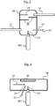
- FIGURE 3 An example of a mixer 98 according to the invention is illustrated in FIGURE 3 .
- the biomass enters the mixer 98 via a feed channel 21, for example connected to the pressurizing pump 93 illustrated in FIG. FIGURE 1 .
- the steam is injected perpendicularly to the supply channel 21.
- acid is also injected into the biomass, inside the interior volume of the mixer 98, by the injection means 97 which comprises an injection head 24.
- the biomass, the steam and the The acid is thus dynamically mixed in the mixer 98, for example and especially under the effect of the differential pressure of steam injection and biomass, preferably greater than 0.2 MPa.
- the biomass enters the mixer with a speed lower than 1 m / s, and the steam is injected into the mixer 98 with a speed greater than 130 m / s, preferably between 200 and 250 m / s .
- the mixture is directed towards the outlet channel 22, for example towards the heating means 94 illustrated in FIG. FIGURE 1 .
- the mixer 98 may comprise a static mixer, for example consisting of baffles 25. In the example of FIG.
- FIGURE 3 the steam is injected obliquely or perpendicular to the direction of movement of the biomass in the interior volume of the mixer 98.
- the steam injection rate corresponds to 20% or less, typically between 10% and 20%, of the flow rate of the biomass moving in the path
- FIG. FIGURE 4 Another example of mixer 98 according to the invention is illustrated in FIG. FIGURE 4 .
- the mixer 98 comprises a wear part 26 to limit or avoid erosion of the part of the mixer 98, in this case. example a pipe, subjected to the vapor flow generated by the steam injection.
- This wear part 26 faces the nozzle 23, and is preferably removable.
- the steam is injected perpendicularly to the direction of movement of the biomass in the interior volume of the mixer 98, the biomass moving in the direction 10.
Landscapes
- Engineering & Computer Science (AREA)
- Chemical & Material Sciences (AREA)
- Organic Chemistry (AREA)
- Life Sciences & Earth Sciences (AREA)
- Hydrology & Water Resources (AREA)
- Environmental & Geological Engineering (AREA)
- Water Supply & Treatment (AREA)
- Mechanical Engineering (AREA)
- General Engineering & Computer Science (AREA)
- Inorganic Chemistry (AREA)
- Processing Of Solid Wastes (AREA)
- Treatment Of Sludge (AREA)
Claims (18)
- Verfahren zum Erwärmen einer Biomasse, die in einer industriellen Behandlungsstrecke bewegt wird, welche einen Eingang (91) für die eintretende Biomasse, eine Druckaufbaupumpe (93), eine Heizvorrichtung (94, 94b) und eine Behandlungsstation (95) umfasst, dadurch gekennzeichnet, dass Dampf in die Strecke zwischen der Druckaufbaupumpe (93) und der Heizvorrichtung (94, 94b) eingespritzt wird
und dass es einen Schritt zum Einspritzen eines Additivs in die Biomasse stromaufwärts von der Heizvorrichtung (94, 94b) umfasst, in dem das Additiv derart in die Biomasse eingespritzt wird, dass das Additiv mit dem eingespritzten Dampf beaufschlagt wird. - Verfahren gemäss Anspruch 1, dadurch gekennzeichnet, dass das Einspritzen des Dampfes und die Heizvorrichtung (94, 94b) derart gesteuert werden, dass die Temperatur der Biomasse vor deren Ankunft in der Behandlungsstation (95) eine parametrierte Temperatur erreicht, wobei die parametrierte Temperatur zwischen 165 °C und 205 °C, vorzugsweise bei 185 °C liegt.
- Verfahren gemäss einem der Ansprüche 1 oder 2, dadurch gekennzeichnet, dass das Einspritzen des Dampfes am Eingang der Heizvorrichtung (94, 94b) zur Steigerung der Temperatur der Biomasse auf einen Wert von über 70 °C gesteuert wird.
- Verfahren gemäss einem der Ansprüche 1 bis 3, dadurch gekennzeichnet, dass der Dampf schräg oder senkrecht zur Bewegungsrichtung der Biomasse in der Strecke oder entgegen der Bewegungsrichtung der Biomasse in der Strecke eingespritzt wird.
- Verfahren gemäss einem der Ansprüche 1 à 4, dadurch gekennzeichnet, dass die Druckaufbaupumpe (93) den Druck der Biomasse bis auf einen Wert erhöht, der das Erwärmen der Biomasse auf eine Temperatur über 100 °C gewährleistet, ohne diese zum Sieden zu bringen.
- Verfahren gemäss Anspruch 5, dadurch gekennzeichnet, dass der Ausgangsdruck der Druckaufbaupumpe (93) höher als 3 MPa ist.
- Verfahren gemäss einem der Ansprüche 1 bis 6, dadurch gekennzeichnet, dass die Strecke ferner eine Kühlstation (96) stromabwärts von der Behandlungsstation (95) aufweist, und dass eine Übertragungsflüssigkeit auf ihrem Weg zwischen der Kühlstation (96) und der Heizvorrichtung (94) erwärmt wird.
- Verfahren gemäss Anspruch 7, dadurch gekennzeichnet, dass die Übertragungsflüssigkeit auf eine Temperatur über jener der Biomasse in der Behandlungsstation (95) erwärmt wird.
- Verfahren gemäss Anspruch 7 oder 8, dadurch gekennzeichnet, dass ein und dieselbe externe Wärmequelle (9T3) zum Erwärmen der Übertragungsflüssigkeit und einer Wärmeträgerflüssigkeit verwendet wird, die ein Ansteigen und/oder eine Erhaltung der Temperatur der Biomasse in der Behandlungsstation (95) gewährleistet, wobei die Wärmeträgerflüssigkeit in einem Mantel (952) der Behandlungsstation (95) zirkuliert.
- Verfahren gemäss einem der Ansprüche 1 bis 9, dadurch gekennzeichnet, dass Wärme der Biomasse stromabwärts von der Behandlungsstation (95) gewonnen wird und dass diese rückgewonnene Wärme stromaufwärts von der Behandlungsstation (95) auf die Biomasse übertragen wird.
- Verfahren gemäss einem der Ansprüche 1 bis 10, dadurch gekennzeichnet, dass Wärme der Biomasse stromabwärts von der Behandlungsstation (95) gewonnen wird und dass diese rückgewonnene Wärme stromaufwärts von der Behandlungsstation (95) auf die Biomasse mittels einer Wärmeaustauschvorrichtung zwischen der aus der Behandlungsstation (95) austretenden Biomasse und der in der Strecke stromaufwärts von der Behandlungsstation (95) zirkulierenden Biomasse übertragen wird.
- Verfahren gemäss einem der Ansprüche 1 bis 11, dadurch gekennzeichnet, dass ein Teil der Biomasse in der Behandlungsstation (95) mittels einer Umlaufleitung (9M) entnommen wird und dass dieser Teil in die Behandlungsstation (95) derart zurückgeführt wird, dass eine Bewegung der Biomasse in der Behandlungsstation (95) erzeugt wird.
- Verfahren gemäss einem der Ansprüche 1 bis 12, dadurch gekennzeichnet, dass der eingespritzte Dampf und die Biomasse in der Strecke zwischen der Druckaufbaupumpe (93) und der Heizvorrichtung (94, 94b) mittels eines Mischers (98) gemischt werden.
- Vorrichtung zur Durchführung eines Verfahrens gemäss einem der Ansprüche 1 bis 13, dadurch gekennzeichnet, dass sie eine industrielle Behandlungsstrecke umfasst, die Folgendes aufweist:- einen Eingang (91), der eingerichtet ist, um eintretende Biomasse in die Strecke einzuleiten,- eine Druckaufbaupumpe (93), die eingerichtet ist, um die Biomasse innerhalb der Strecke zu bewegen,- eine Heizvorrichtung (94), die geeignet ist, um die Biomasse zu erwärmen,- eine Behandlungsstation (95), die geeignet ist, um die Biomasse im wesentlichen bei einer Eingangstemperatur in der Behandlungsstation (95) zu erhalten, wobei die Behandlungsstation (95) stromabwärts von der Heizvorrichtung (94) eingerichtet ist,- eine Wärmeaustauschvorrichtung zwischen der Biomasse, die aus der Behandlungsstation (95) austritt und der Biomasse, die innerhalb der Strecke stromaufwärts von der Behandlungsstation (95) zirkuliert,- eine Wasserdampferzeugungsvorrichtung (981),- einen Mischer (98), der eingerichtet ist, um den von der Wasserdampferzeugungsvorrichtung (981) erzeugten Wasserdampf und die Biomasse in der Strecke zwischen der Druckaufbaupumpe (93) und der Heizvorrichtung (94, 94b) zu mischen, und- eine Additiveinspritzvorrichtung, die eingerichtet ist, um ein Additiv derart in die Biomasse stromaufwärts von der Heizvorrichtung (94, 94b) einzuspritzen, dass das Additiv mit dem eingespritzten Dampf beaufschlagt wird.
- Vorrichtung gemäss Anspruch 14, dadurch gekennzeichnet, dass der Mischer (98) einen statischen Mischer umfasst.
- Vorrichtung gemäss Anspruch 14 oder 15, dadurch gekennzeichnet, dass die Wärmeaustauschvorrichtung Folgendes umfasst:- einen Übertragungskreislauf (9T), in dem eine Übertragungsflüssigkeit derart zirkuliert, dass die Biomasse in der Heizvorrichtung (94, 94b) durch Wärmeaustausch zwischen der Übertragungsflüssigkeit und der Biomasse erwärmt wird, und- Mittel zur Erzeugung eines Umlaufs (9T1) der Übertragungsflüssigkeit, die geeignet sind, um die Übertragungsflüssigkeit in dem Übertragungskreislauf (9T) zirkulieren zu lassen.
- Vorrichtung gemäss Anspruch 16, dadurch gekennzeichnet, dass sie ferner eine externe Wärmequelle (9T3) umfasst, die eingerichtet ist, um die Übertragungsflüssigkeit und eine Wärmeträgerflüssigkeit, welche in einem Mantel (952) der Behandlungsstation (95) zirkuliert, zu erwärmen.
- Vorrichtung gemäss einem der Ansprüche 14 bis 15, dadurch gekennzeichnet, dass die Behandlungsstation (95) derart eingerichtet ist, dass die Biomasse durch einen unteren Abschnitt (953) in die Behandlungsstation (95) eintritt und durch einen oberen Abschnitt (954) aus ihr austritt.
Applications Claiming Priority (2)
| Application Number | Priority Date | Filing Date | Title |
|---|---|---|---|
| FR1460616A FR3027894B1 (fr) | 2014-11-04 | 2014-11-04 | Procede de carbonisation hydrothermale d'une biomasse, et dispositif s'y rapportant |
| PCT/IB2015/058468 WO2016071828A1 (fr) | 2014-11-04 | 2015-11-02 | Procede de carbonisation hydrothermale d'une biomasse, et dispositif s'y rapportant |
Publications (2)
| Publication Number | Publication Date |
|---|---|
| EP3148719A1 EP3148719A1 (de) | 2017-04-05 |
| EP3148719B1 true EP3148719B1 (de) | 2018-08-22 |
Family
ID=52627318
Family Applications (1)
| Application Number | Title | Priority Date | Filing Date |
|---|---|---|---|
| EP15798220.8A Active EP3148719B1 (de) | 2014-11-04 | 2015-11-02 | Verfahren zur hydrothermalen karbonisierung von biomasse und zugehörige vorrichtung |
Country Status (7)
| Country | Link |
|---|---|
| US (1) | US10800692B2 (de) |
| EP (1) | EP3148719B1 (de) |
| CN (1) | CN106687415B (de) |
| AU (1) | AU2015344481B2 (de) |
| ES (1) | ES2693548T3 (de) |
| FR (1) | FR3027894B1 (de) |
| WO (1) | WO2016071828A1 (de) |
Families Citing this family (4)
| Publication number | Priority date | Publication date | Assignee | Title |
|---|---|---|---|---|
| EP3372657B1 (de) | 2017-03-10 | 2019-09-25 | HTCycle GmbH | Vorrichtung zur durchführung einer hydrothermalen karbonisierungsreaktion |
| CN108218176A (zh) * | 2017-12-07 | 2018-06-29 | 上海梵煦环境科技有限公司 | 一种污泥碳化一体机及方法 |
| FR3151386B1 (fr) * | 2023-07-17 | 2025-07-18 | Commissariat Energie Atomique | Refroidisseur de produit(s) issu(s) d’un réacteur thermochimique, Installation de liquéfaction ou de carbonisation hydrothermale intégrant un tel refroidisseur. |
| IT202300017376A1 (it) * | 2023-08-18 | 2025-02-18 | Hbi S R L | Processo ed impianto di carbonizzazione idrotermica |
Family Cites Families (8)
| Publication number | Priority date | Publication date | Assignee | Title |
|---|---|---|---|---|
| US3962076A (en) * | 1972-11-06 | 1976-06-08 | Texaco Inc. | Process for converting aqueous sewage to potable water |
| US6905600B2 (en) * | 2001-11-16 | 2005-06-14 | Ch2M Hill, Inc. | Method and apparatus for the treatment of particulate biodegradable organic waste |
| US7909895B2 (en) * | 2004-11-10 | 2011-03-22 | Enertech Environmental, Inc. | Slurry dewatering and conversion of biosolids to a renewable fuel |
| EP2206688A1 (de) * | 2008-12-16 | 2010-07-14 | Suncoal Industries Gmbh | Thermo-chemische Aufbereitung des Processwassers einer hydrothermalen Karbonisierung |
| DE102009055976A1 (de) * | 2009-11-27 | 2011-06-01 | Choren Industries Gmbh | Vorrichtung und Verfahren zur Erzeugung eines Synthesegases aus Biomasse durch Flugstrom-Vergasung |
| EP2388305A3 (de) * | 2010-05-17 | 2012-01-25 | TerraNova Energy GmbH | Thermische Verwertung fester Brennstoffe |
| DE102011001108B4 (de) * | 2011-03-04 | 2015-03-12 | Ava-Co2 Schweiz Ag | Verfahren und Vorrichtung zur hydrothermalen Karbonisierung |
| ES2393464B1 (es) * | 2011-06-09 | 2013-11-18 | Ingelia, S.L. | Procedimiento para la extracción de productos bioquímicos obtenidos a partir de un proceso de carbonización hidrotermal de biomasa. |
-
2014
- 2014-11-04 FR FR1460616A patent/FR3027894B1/fr active Active
-
2015
- 2015-11-02 US US15/324,985 patent/US10800692B2/en active Active
- 2015-11-02 CN CN201580043704.XA patent/CN106687415B/zh active Active
- 2015-11-02 EP EP15798220.8A patent/EP3148719B1/de active Active
- 2015-11-02 ES ES15798220.8T patent/ES2693548T3/es active Active
- 2015-11-02 AU AU2015344481A patent/AU2015344481B2/en active Active
- 2015-11-02 WO PCT/IB2015/058468 patent/WO2016071828A1/fr not_active Ceased
Non-Patent Citations (1)
| Title |
|---|
| None * |
Also Published As
| Publication number | Publication date |
|---|---|
| WO2016071828A1 (fr) | 2016-05-12 |
| AU2015344481A1 (en) | 2017-02-02 |
| US20170210657A1 (en) | 2017-07-27 |
| FR3027894A1 (fr) | 2016-05-06 |
| FR3027894B1 (fr) | 2019-05-24 |
| CN106687415A (zh) | 2017-05-17 |
| US10800692B2 (en) | 2020-10-13 |
| EP3148719A1 (de) | 2017-04-05 |
| AU2015344481B2 (en) | 2020-08-27 |
| CN106687415B (zh) | 2020-10-09 |
| ES2693548T3 (es) | 2018-12-12 |
Similar Documents
| Publication | Publication Date | Title |
|---|---|---|
| EP3287510B1 (de) | Hydrothermales karbonisierungsverfahren einer biomasse, und dazu verwendete vorrichtung | |
| EP3148719B1 (de) | Verfahren zur hydrothermalen karbonisierung von biomasse und zugehörige vorrichtung | |
| CA2897980C (fr) | Dispositif d'oxydation hydrothermale pour le traitement d'une matiere dans un milieu supercritique et procede de mise en oeuvre | |
| EP3303922B1 (de) | Krackofen | |
| EP3152167B1 (de) | Hydrothermalkarbonisationsverfahren und vorrichtung mit optimiertem schlamm- und dampfmischen | |
| EP3152166B1 (de) | Hydrothermaler karbonisierungsreaktor mit optimierter schlamm- und dampfmischung | |
| CA2917685C (fr) | Procede de carbonisation hydrothermale optimise et installation pour sa mise en oeuvre. | |
| CH700655B1 (fr) | Procédé et dispositif de traitement par oxydation par voie humide de déchets liquides contenant des charges en matières minérales. | |
| EP3806995B1 (de) | Reaktor zur hydrothermalen oxidationsbehandlung eines organischen stoffes in einem reaktionsmedium | |
| EP4139064B1 (de) | Verfeinerungsmachine, verfeinerungsanlage und verfeinerungsprozess für die verarbeitung von komposit-produkten | |
| FR2891161A1 (fr) | Reacteur et procede pour le traitement en anoxie d'une matiere dans un milieu reactionnel fluide | |
| FR2924201A1 (fr) | Procede de chauffage au moyen d'un oxybruleur comportant un injecteur dispose a l'interieur d'un bloc | |
| FR2975754A1 (fr) | Chaudiere a vapeur avec insert | |
| WO2013011447A1 (fr) | Procédé et installation pour effectuer en continu l'hydrolyse de matières organiques, en particulier de boues produites lors du traitement des eaux | |
| FR2995715A3 (fr) | Procede et dispositif de traitement par oxydation par voie humide de dechets liquides radioactifs contenant des charges de matieres diverses | |
| CA2901711A1 (fr) | Procede de generation de vapeur d'eau a partir d'une eau brute, en particulier d'une eau de purge sortant d'un generateur de vapeur | |
| FR3047298B1 (fr) | Dispositif de recirculation de gaz | |
| WO2021123695A1 (fr) | Réacteur échangeur thermique | |
| FR3036178A1 (fr) | Procede de refroidissement d'une source chaude destinee a echanger avec un fluide de travail d'un systeme thermodynamique, installation mettant en œuvre ce procede et systeme thermodynamique |
Legal Events
| Date | Code | Title | Description |
|---|---|---|---|
| PUAI | Public reference made under article 153(3) epc to a published international application that has entered the european phase |
Free format text: ORIGINAL CODE: 0009012 |
|
| 17P | Request for examination filed |
Effective date: 20170102 |
|
| AK | Designated contracting states |
Kind code of ref document: A1 Designated state(s): AL AT BE BG CH CY CZ DE DK EE ES FI FR GB GR HR HU IE IS IT LI LT LU LV MC MK MT NL NO PL PT RO RS SE SI SK SM TR |
|
| AX | Request for extension of the european patent |
Extension state: BA ME |
|
| DAV | Request for validation of the european patent (deleted) | ||
| DAX | Request for extension of the european patent (deleted) | ||
| REG | Reference to a national code |
Ref country code: DE Ref legal event code: R079 Ref document number: 602015015246 Country of ref document: DE Free format text: PREVIOUS MAIN CLASS: B09B0003000000 Ipc: C01B0032050000 |
|
| RIC1 | Information provided on ipc code assigned before grant |
Ipc: C01B 32/05 20170101AFI20180213BHEP Ipc: C02F 1/00 20060101ALI20180213BHEP Ipc: C02F 11/10 20060101ALI20180213BHEP Ipc: C02F 103/00 20060101ALI20180213BHEP Ipc: F23G 5/027 20060101ALI20180213BHEP |
|
| GRAP | Despatch of communication of intention to grant a patent |
Free format text: ORIGINAL CODE: EPIDOSNIGR1 |
|
| INTG | Intention to grant announced |
Effective date: 20180320 |
|
| GRAS | Grant fee paid |
Free format text: ORIGINAL CODE: EPIDOSNIGR3 |
|
| GRAA | (expected) grant |
Free format text: ORIGINAL CODE: 0009210 |
|
| AK | Designated contracting states |
Kind code of ref document: B1 Designated state(s): AL AT BE BG CH CY CZ DE DK EE ES FI FR GB GR HR HU IE IS IT LI LT LU LV MC MK MT NL NO PL PT RO RS SE SI SK SM TR |
|
| REG | Reference to a national code |
Ref country code: GB Ref legal event code: FG4D Free format text: NOT ENGLISH |
|
| REG | Reference to a national code |
Ref country code: CH Ref legal event code: EP |
|
| REG | Reference to a national code |
Ref country code: AT Ref legal event code: REF Ref document number: 1032235 Country of ref document: AT Kind code of ref document: T Effective date: 20180915 |
|
| REG | Reference to a national code |
Ref country code: FR Ref legal event code: PLFP Year of fee payment: 4 |
|
| REG | Reference to a national code |
Ref country code: IE Ref legal event code: FG4D Free format text: LANGUAGE OF EP DOCUMENT: FRENCH |
|
| REG | Reference to a national code |
Ref country code: DE Ref legal event code: R096 Ref document number: 602015015246 Country of ref document: DE |
|
| REG | Reference to a national code |
Ref country code: ES Ref legal event code: FG2A Ref document number: 2693548 Country of ref document: ES Kind code of ref document: T3 Effective date: 20181212 |
|
| REG | Reference to a national code |
Ref country code: NL Ref legal event code: MP Effective date: 20180822 |
|
| REG | Reference to a national code |
Ref country code: LT Ref legal event code: MG4D |
|
| PG25 | Lapsed in a contracting state [announced via postgrant information from national office to epo] |
Ref country code: NL Free format text: LAPSE BECAUSE OF FAILURE TO SUBMIT A TRANSLATION OF THE DESCRIPTION OR TO PAY THE FEE WITHIN THE PRESCRIBED TIME-LIMIT Effective date: 20180822 Ref country code: BG Free format text: LAPSE BECAUSE OF FAILURE TO SUBMIT A TRANSLATION OF THE DESCRIPTION OR TO PAY THE FEE WITHIN THE PRESCRIBED TIME-LIMIT Effective date: 20181122 Ref country code: LT Free format text: LAPSE BECAUSE OF FAILURE TO SUBMIT A TRANSLATION OF THE DESCRIPTION OR TO PAY THE FEE WITHIN THE PRESCRIBED TIME-LIMIT Effective date: 20180822 Ref country code: SE Free format text: LAPSE BECAUSE OF FAILURE TO SUBMIT A TRANSLATION OF THE DESCRIPTION OR TO PAY THE FEE WITHIN THE PRESCRIBED TIME-LIMIT Effective date: 20180822 Ref country code: IS Free format text: LAPSE BECAUSE OF FAILURE TO SUBMIT A TRANSLATION OF THE DESCRIPTION OR TO PAY THE FEE WITHIN THE PRESCRIBED TIME-LIMIT Effective date: 20181222 Ref country code: NO Free format text: LAPSE BECAUSE OF FAILURE TO SUBMIT A TRANSLATION OF THE DESCRIPTION OR TO PAY THE FEE WITHIN THE PRESCRIBED TIME-LIMIT Effective date: 20181122 Ref country code: GR Free format text: LAPSE BECAUSE OF FAILURE TO SUBMIT A TRANSLATION OF THE DESCRIPTION OR TO PAY THE FEE WITHIN THE PRESCRIBED TIME-LIMIT Effective date: 20181123 Ref country code: FI Free format text: LAPSE BECAUSE OF FAILURE TO SUBMIT A TRANSLATION OF THE DESCRIPTION OR TO PAY THE FEE WITHIN THE PRESCRIBED TIME-LIMIT Effective date: 20180822 Ref country code: RS Free format text: LAPSE BECAUSE OF FAILURE TO SUBMIT A TRANSLATION OF THE DESCRIPTION OR TO PAY THE FEE WITHIN THE PRESCRIBED TIME-LIMIT Effective date: 20180822 |
|
| REG | Reference to a national code |
Ref country code: AT Ref legal event code: MK05 Ref document number: 1032235 Country of ref document: AT Kind code of ref document: T Effective date: 20180822 |
|
| PG25 | Lapsed in a contracting state [announced via postgrant information from national office to epo] |
Ref country code: AL Free format text: LAPSE BECAUSE OF FAILURE TO SUBMIT A TRANSLATION OF THE DESCRIPTION OR TO PAY THE FEE WITHIN THE PRESCRIBED TIME-LIMIT Effective date: 20180822 Ref country code: HR Free format text: LAPSE BECAUSE OF FAILURE TO SUBMIT A TRANSLATION OF THE DESCRIPTION OR TO PAY THE FEE WITHIN THE PRESCRIBED TIME-LIMIT Effective date: 20180822 Ref country code: LV Free format text: LAPSE BECAUSE OF FAILURE TO SUBMIT A TRANSLATION OF THE DESCRIPTION OR TO PAY THE FEE WITHIN THE PRESCRIBED TIME-LIMIT Effective date: 20180822 |
|
| PG25 | Lapsed in a contracting state [announced via postgrant information from national office to epo] |
Ref country code: EE Free format text: LAPSE BECAUSE OF FAILURE TO SUBMIT A TRANSLATION OF THE DESCRIPTION OR TO PAY THE FEE WITHIN THE PRESCRIBED TIME-LIMIT Effective date: 20180822 Ref country code: PL Free format text: LAPSE BECAUSE OF FAILURE TO SUBMIT A TRANSLATION OF THE DESCRIPTION OR TO PAY THE FEE WITHIN THE PRESCRIBED TIME-LIMIT Effective date: 20180822 Ref country code: AT Free format text: LAPSE BECAUSE OF FAILURE TO SUBMIT A TRANSLATION OF THE DESCRIPTION OR TO PAY THE FEE WITHIN THE PRESCRIBED TIME-LIMIT Effective date: 20180822 Ref country code: CZ Free format text: LAPSE BECAUSE OF FAILURE TO SUBMIT A TRANSLATION OF THE DESCRIPTION OR TO PAY THE FEE WITHIN THE PRESCRIBED TIME-LIMIT Effective date: 20180822 Ref country code: RO Free format text: LAPSE BECAUSE OF FAILURE TO SUBMIT A TRANSLATION OF THE DESCRIPTION OR TO PAY THE FEE WITHIN THE PRESCRIBED TIME-LIMIT Effective date: 20180822 |
|
| REG | Reference to a national code |
Ref country code: DE Ref legal event code: R097 Ref document number: 602015015246 Country of ref document: DE |
|
| PG25 | Lapsed in a contracting state [announced via postgrant information from national office to epo] |
Ref country code: SK Free format text: LAPSE BECAUSE OF FAILURE TO SUBMIT A TRANSLATION OF THE DESCRIPTION OR TO PAY THE FEE WITHIN THE PRESCRIBED TIME-LIMIT Effective date: 20180822 Ref country code: SM Free format text: LAPSE BECAUSE OF FAILURE TO SUBMIT A TRANSLATION OF THE DESCRIPTION OR TO PAY THE FEE WITHIN THE PRESCRIBED TIME-LIMIT Effective date: 20180822 Ref country code: DK Free format text: LAPSE BECAUSE OF FAILURE TO SUBMIT A TRANSLATION OF THE DESCRIPTION OR TO PAY THE FEE WITHIN THE PRESCRIBED TIME-LIMIT Effective date: 20180822 |
|
| REG | Reference to a national code |
Ref country code: DE Ref legal event code: R119 Ref document number: 602015015246 Country of ref document: DE |
|
| PLBE | No opposition filed within time limit |
Free format text: ORIGINAL CODE: 0009261 |
|
| REG | Reference to a national code |
Ref country code: CH Ref legal event code: PL |
|
| STAA | Information on the status of an ep patent application or granted ep patent |
Free format text: STATUS: NO OPPOSITION FILED WITHIN TIME LIMIT |
|
| 26N | No opposition filed |
Effective date: 20190523 |
|
| PG25 | Lapsed in a contracting state [announced via postgrant information from national office to epo] |
Ref country code: LU Free format text: LAPSE BECAUSE OF NON-PAYMENT OF DUE FEES Effective date: 20181102 Ref country code: MC Free format text: LAPSE BECAUSE OF FAILURE TO SUBMIT A TRANSLATION OF THE DESCRIPTION OR TO PAY THE FEE WITHIN THE PRESCRIBED TIME-LIMIT Effective date: 20180822 |
|
| REG | Reference to a national code |
Ref country code: BE Ref legal event code: MM Effective date: 20181130 |
|
| REG | Reference to a national code |
Ref country code: IE Ref legal event code: MM4A |
|
| PG25 | Lapsed in a contracting state [announced via postgrant information from national office to epo] |
Ref country code: LI Free format text: LAPSE BECAUSE OF NON-PAYMENT OF DUE FEES Effective date: 20181130 Ref country code: CH Free format text: LAPSE BECAUSE OF NON-PAYMENT OF DUE FEES Effective date: 20181130 Ref country code: SI Free format text: LAPSE BECAUSE OF FAILURE TO SUBMIT A TRANSLATION OF THE DESCRIPTION OR TO PAY THE FEE WITHIN THE PRESCRIBED TIME-LIMIT Effective date: 20180822 |
|
| PG25 | Lapsed in a contracting state [announced via postgrant information from national office to epo] |
Ref country code: IE Free format text: LAPSE BECAUSE OF NON-PAYMENT OF DUE FEES Effective date: 20181102 Ref country code: DE Free format text: LAPSE BECAUSE OF NON-PAYMENT OF DUE FEES Effective date: 20190601 |
|
| PG25 | Lapsed in a contracting state [announced via postgrant information from national office to epo] |
Ref country code: BE Free format text: LAPSE BECAUSE OF NON-PAYMENT OF DUE FEES Effective date: 20181130 |
|
| PG25 | Lapsed in a contracting state [announced via postgrant information from national office to epo] |
Ref country code: MT Free format text: LAPSE BECAUSE OF FAILURE TO SUBMIT A TRANSLATION OF THE DESCRIPTION OR TO PAY THE FEE WITHIN THE PRESCRIBED TIME-LIMIT Effective date: 20180822 |
|
| PG25 | Lapsed in a contracting state [announced via postgrant information from national office to epo] |
Ref country code: TR Free format text: LAPSE BECAUSE OF FAILURE TO SUBMIT A TRANSLATION OF THE DESCRIPTION OR TO PAY THE FEE WITHIN THE PRESCRIBED TIME-LIMIT Effective date: 20180822 |
|
| PG25 | Lapsed in a contracting state [announced via postgrant information from national office to epo] |
Ref country code: PT Free format text: LAPSE BECAUSE OF FAILURE TO SUBMIT A TRANSLATION OF THE DESCRIPTION OR TO PAY THE FEE WITHIN THE PRESCRIBED TIME-LIMIT Effective date: 20180822 |
|
| PG25 | Lapsed in a contracting state [announced via postgrant information from national office to epo] |
Ref country code: CY Free format text: LAPSE BECAUSE OF FAILURE TO SUBMIT A TRANSLATION OF THE DESCRIPTION OR TO PAY THE FEE WITHIN THE PRESCRIBED TIME-LIMIT Effective date: 20180822 Ref country code: MK Free format text: LAPSE BECAUSE OF NON-PAYMENT OF DUE FEES Effective date: 20180822 Ref country code: HU Free format text: LAPSE BECAUSE OF FAILURE TO SUBMIT A TRANSLATION OF THE DESCRIPTION OR TO PAY THE FEE WITHIN THE PRESCRIBED TIME-LIMIT; INVALID AB INITIO Effective date: 20151102 |
|
| P01 | Opt-out of the competence of the unified patent court (upc) registered |
Effective date: 20230601 |
|
| PGFP | Annual fee paid to national office [announced via postgrant information from national office to epo] |
Ref country code: GB Payment date: 20251127 Year of fee payment: 11 |
|
| PGFP | Annual fee paid to national office [announced via postgrant information from national office to epo] |
Ref country code: IT Payment date: 20251119 Year of fee payment: 11 |
|
| PGFP | Annual fee paid to national office [announced via postgrant information from national office to epo] |
Ref country code: FR Payment date: 20251125 Year of fee payment: 11 |
|
| PGFP | Annual fee paid to national office [announced via postgrant information from national office to epo] |
Ref country code: ES Payment date: 20251201 Year of fee payment: 11 |